EP2076064A1 - Appareil auditif comportant un moulage et un module de sortie - Google Patents
Appareil auditif comportant un moulage et un module de sortie Download PDFInfo
- Publication number
- EP2076064A1 EP2076064A1 EP07124085A EP07124085A EP2076064A1 EP 2076064 A1 EP2076064 A1 EP 2076064A1 EP 07124085 A EP07124085 A EP 07124085A EP 07124085 A EP07124085 A EP 07124085A EP 2076064 A1 EP2076064 A1 EP 2076064A1
- Authority
- EP
- European Patent Office
- Prior art keywords
- output module
- mould
- hearing device
- venting
- venting channel
- Prior art date
- Legal status (The legal status is an assumption and is not a legal conclusion. Google has not performed a legal analysis and makes no representation as to the accuracy of the status listed.)
- Granted
Links
Images


Classifications
-
- H—ELECTRICITY
- H04—ELECTRIC COMMUNICATION TECHNIQUE
- H04R—LOUDSPEAKERS, MICROPHONES, GRAMOPHONE PICK-UPS OR LIKE ACOUSTIC ELECTROMECHANICAL TRANSDUCERS; DEAF-AID SETS; PUBLIC ADDRESS SYSTEMS
- H04R25/00—Deaf-aid sets, i.e. electro-acoustic or electro-mechanical hearing aids; Electric tinnitus maskers providing an auditory perception
- H04R25/65—Housing parts, e.g. shells, tips or moulds, or their manufacture
- H04R25/652—Ear tips; Ear moulds
-
- H—ELECTRICITY
- H04—ELECTRIC COMMUNICATION TECHNIQUE
- H04R—LOUDSPEAKERS, MICROPHONES, GRAMOPHONE PICK-UPS OR LIKE ACOUSTIC ELECTROMECHANICAL TRANSDUCERS; DEAF-AID SETS; PUBLIC ADDRESS SYSTEMS
- H04R2460/00—Details of hearing devices, i.e. of ear- or headphones covered by H04R1/10 or H04R5/033 but not provided for in any of their subgroups, or of hearing aids covered by H04R25/00 but not provided for in any of its subgroups
- H04R2460/11—Aspects relating to vents, e.g. shape, orientation, acoustic properties in ear tips of hearing devices to prevent occlusion
-
- H—ELECTRICITY
- H04—ELECTRIC COMMUNICATION TECHNIQUE
- H04R—LOUDSPEAKERS, MICROPHONES, GRAMOPHONE PICK-UPS OR LIKE ACOUSTIC ELECTROMECHANICAL TRANSDUCERS; DEAF-AID SETS; PUBLIC ADDRESS SYSTEMS
- H04R25/00—Deaf-aid sets, i.e. electro-acoustic or electro-mechanical hearing aids; Electric tinnitus maskers providing an auditory perception
- H04R25/65—Housing parts, e.g. shells, tips or moulds, or their manufacture
- H04R25/658—Manufacture of housing parts
Definitions
- the present invention refers to a hearing device comprising an ear mould, and specifically to a hearing device having a venting channel arrangement.
- a venting channel to provide suitable ventilation and to avoid the undesired occlusion effect, which reduces comfort for the user.
- the occlusion effect is caused when a hearing aid (here termed hearing device) or any part thereof is inserted into the user's ear canal and thereby defines a sealed or closed portion of the user's ear canal between the hearing aid or the part thereof and the user's ear drum.
- a venting channel in a hearing aid which is effective in view of providing a pressure balance in the user's ear canal and thereby reducing the occlusion effect, requires a certain diameter or certain dimensions to obtain the desired result. This reduces flexibility when manufacturing the hearing aid since a certain space of the hearing aid mould is occupied by the venting channel.
- the output transducer is a speaker or earphone (also known as a receiver) for producing sound waves directed to a user's eardrum.
- the output module may be, preferably tightly, fit into a mould and the at least one venting channel is arranged between the mould and an outer surface of the output module.
- the mould is arranged to have an opening with an inner surface, the dimensions and form of outer surface of the output module, the opening and the inner surface of the mould being adapted to allow the output module to be mounted in the opening, preferably tightly, at least over a part of their common spatial extension.
- the at least one venting channel is arranged between the inner surface of the mould and an outer surface of the output module, when the output module is mounted in the opening of the mould.
- a plurality of venting channels may be arranged around the output module extending along a longitudinal axis thereof.
- the plurality of venting channels can each be provided by a recessed portion on an outer surface of the output module along a longitudinal axis (axial direction) thereof.
- one or more venting channels can be formed in the inner surface of the mould facing the outer surface of the output module, when the output module is mounted in the mould in an operational position.
- one or more venting channels can be arranged between the outer surface of the output module and the inner surface of the mould by arranging one or more ridges in one of (or both) surfaces, the one or more ridges having a component of extension in an axial direction of the output module.
- the plurality of venting channels leads to a compact and space-saving arrangement of the hearing device.
- the corresponding cross-sectional area distributed on a number of (necessarily smaller) vent channels provides substantially the same effect at relatively low frequencies (e.g. lower than 2 kHz), but such an arrangement has a larger acoustical attenuation at relatively higher frequencies (e.g. larger than 2 kHz).
- the insertion of a porous material into the venting channels (over a part or all of the longitudinal extension of the vent) provides an additional possibility to control the acoustic attenuation of a venting channel of a given cross-sectional area and longitudinal extension.
- a specific cross-sectional area of a single, air-filled tubular vent to provide an intended reduction of the occlusion effect is determined (for a given ear canal and enclosed volume).
- the resulting effect on occlusion is maintained (mainly determined by the low-frequency part of the signal), but with an increased feedback margin at higher frequencies (e.g. > 2 kHz) due to the increased attenuation at these frequencies.
- the cross-sectional shape of an individual venting channel can have any appropriate form, e.g. rectangular (such as square) or elliptical (such as circular) of triangular (e.g. a groove).
- the cross-sectional shapes of the number of vents will be identical. They may however be different, e.g. depending on the needed attenuation, particular geometrical constraints, etc.
- the cross-sectional shape of a vent is identical over its longitudinal extension. This need not be the case, however.
- the cross-sectional form and/or area changes along the length of the vent, e.g. increasing from one end to the other.
- the vent has a larger cross-sectional area at the end facing the enclosed volume (cf. B in Fig. 1 ) than at the end facing the outside (cf. A in Fig. 1 ), thereby providing an improved 'collection' of sound vibrations in the enclosed volume.
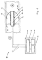
- the present invention is described in the following in conjunction with the schematic diagram of Fig. 1 showing an overall view (cross-sectional view in part) of the structure and arrangement of a hearing device 10 according to the first embodiment of the present invention.
- the hearing device 10 comprises three separate physical bodies, 1) circuitry unit 11, 2) mould 18 and 3) output module 15 mounted in a through-going opening of the mould, the circuitry unit and the output module being electrically connected.
- the circuitry unit 11 can e.g. form part of a module located behind the ear of a user.
- the hearing device 10 comprises a casing, (shell) at least enclosing electronic circuitry providing a signal processing unit of the hearing device.
- the electronic circuitry comprises a circuitry unit 11 comprising a central control unit 12 (controller) that controls the hearing device 10 to be worn by the user.
- the central control unit 12 is connected to an input unit 13 which may be a microphone (such as a directional microphone system, possibly comprising a number of differently located microphones) for picking up sound signals (sound pressure information) of any sound or noise surrounding the user.
- the input unit 13 may be a sensor for sensing an electric signal representing a sound signal picked up otherwise.
- the components of the circuitry unit 11, such as the central control unit 12 and the input unit 13 are powered by the power supply unit 14.
- the power supply unit 14 may comprise any suitable battery or rechargeable battery.
- the processed sound signals (in electric form) are fed to and are received by an output module 15 comprising an output transducer (receiver 16), which is connected to the central control unit 12 via an electric wiring W (here two wires are shown, but any appropriate number of wires can be used).
- such transmission can be performed via a wireless coupling, e.g. an inductive coupling between inductive coils of the circuitry unit and the output module, respectively.
- the transmission from one unit to the other could alternatively be by any other appropriate means, e.g. optical or acoustic.
- the output module 15 is located remote (separate) from the circuitry unit 11 of the hearing device 10 as discussed above, and is - when in operation - arranged in an ear canal EC of the user.
- RITE Receiver In The Ear
- the mould 18 basically closes the user's ear canal EC and defines a closed or sealed portion or volume B in the user's ear canal EC between the mould 18 (in conjunction with the output module 15) and the user's ear drum (not shown in Fig. 1 ).
- a portion A of the user's ear canal EC is the portion thereof which opens to the outside. This open portion A receives to a certain extent any sound or noise (sound signals, sound pressure) from the outside, i.e. the prevailing noise and sound surrounding the user.
- the mould 18 When mounted in an operational state of a user's ear canal, the mould 18 separates the open portion A and the closed portion B of the user's ear canal.
- the cross-sectional diameter of a typical circular vent can e.g. be 1.4 mm when formed as one tubular vent in a micro-mould.
- a corresponding vent area can e.g. be distributed on 3 smaller vent channels, each possibly having a semi-circular or rectangular form.
- the total area of the three identical vents will be approximately equal to that of the 1.4 mm diameter single vent.
- the semi-circular vents could - as an alternative to one large vent running parallel to the module through the mould - be made as grooves in the outer surface of the output module (also termed the receiver module) and/or in the inner surface of the opening.
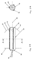
- Figs. 2A and 2B For the further description of the arrangement of the at least one venting channel 19 according to the present invention, reference is now made to Figs. 2A and 2B .
- the at least one venting channel 19 extends substantially along a longitudinal axis 20 of the output module 15 (the longitudinal axis 20 being the direction in which the tube-shaped output module 15 extends, the axial direction) and is directly arranged on the output module 15, that is, on the outer surface of housing 17.
- the at least one venting channel 19 may be basically parallel to the longitudinal axis 20.
- Fig. 2B shows a cross-sectional view of the housing 17 accommodating the output module and being provided with the at least one venting channel 19 along the line A-A shown in Fig. 2A .
- the mould 18 in which the output module is inserted is not shown in Fig. 2B , but is anticipated to have an opening whose cross-section match that of the output module (at least over a part of its longitudinal extension) to provide a fitting match, when the output module is inserted in the mould, which allows the venting of the closed part (B in Fig. 1 ) of the ear canal to be controlled by the venting channels 19.
- the channel(s) 19, may alternatively (or additionally) be formed by grooves in the inner surface of the opening of the mould. This has the advantage that a substantially smooth (e.g. circular) periphery of housing 17 of the output module can be used to 'close' the groove(s) in the inner surface and to thereby form the vent channel(s) 19.
- the at least one venting channel 19 or the plural venting channels 19 as outlined in Fig. 2B together represent the effect of one single bigger venting channel. That is, the plural venting channels 19 according to the first embodiment of the present invention, each having a smaller effective diameter than one bigger venting channel, are e.g. arranged such that the combination of the plural venting channels 19 basically provide an effective diameter corresponding to one bigger venting channel according to the references above but the plural venting channels 19 do not provide the disadvantages of one single bigger venting channel.
- the axial length L vent (z) of the venting channels 19 is longer than the length of the fitting opening of the mould L mould (z), so that a ventilation of the closed volume (B in Fig. 1 ) can be achieved when the output module is mounted in the mould and the mould is mounted in its operational location in the ear canal of a user.
- the porous filter material is chosen to preferably have an acoustically damping effect at relatively higher frequencies (e.g. f > 2 kHz).
- the porous filter material may additionally attenuate unintentional longitudinal vent resonances at even higher frequencies (e.g. f > 8 kHz).
- the filter material is a sintered plastic material.
- the filter material is a composite material, e.g. comprising a matrix of fibres.
- the filter material is an open pore polyethylene.
- the filter material is a foam ceramic.
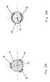
- the plural venting channels 19 are preferably evenly distributed in the circumferential direction of the housing 17.
- the present invention is, however, not limited to such a distribution of the plural venting channels 19, but any further suitable predetermined distribution with symmetry or not can be provided.
- the determination of an arrangement of the plural venting channels 19 departing from the basically symmetric arrangement shown in Fig. 2B as well as the determination of a suitable number of venting channels 19 having the smaller effective diameter depend upon the conditions for adapting the hearing device 10 to the hearing loss of the user (amplification), the structure of the user's ear canal EC and the user's preferences.
- FIG. 3A and 3B A different shape, arrangement and positioning of particular venting channels 19 is shown in Figs. 3A and 3B .
- the channel(s) 19 may further, alternatively (or additionally), be formed by grooves in the inner surface of the opening of the mould.
- the present invention is however not limited to the example of an arrangement of the venting channels 19 on the output module 15 as shown in Fig. 3B .
- the number of venting channels 19 can be modified and the positioning or distribution of the venting channels 19 on the circumferential surface of the output module 15 is not limited to the situation shown in Fig. 3B and also not limited to symmetry. That is, a higher number of venting channels can be implemented, the venting channels basically extending along the longitudinal axis 20 of the output module 15. Further, other shapes and/or cross-sectional areas of the vent channels can be provided according to the requirements of the particular case.
- the porous material may be inserted to fill this particular venting channel 19 partly or completely with the porous material.
- more than one of the plurality of venting channels 19 or all the venting channels 19 may be provided with the porous material at least partly or completely.
- a better feedback margin for a given size of the at least one venting channel 19 is obtained due to the fact that the openings of the at least one venting channel 19 are located very close to the output portion of the output module 15 (receiver) since the at least one venting channel or the plural venting channels are arranged on the outer surface of the output module 15. This has a positive effect on the feedback margin at mid-range frequencies or frequency components. The exact improvement depends on the size of the residual sealed portion B (cavity) of the user's ear canal EC.
- venting channels 19 or a plurality of venting channels 19 each having a relatively small cross-sectional area makes it possible to insert the output module 15 into a small mould (micro mould) having relatively small dimensions (e.g. in the mm-range e.g. cross-sectional dimensions of 5 mm in diameter and a length of 7 mm in an axial direction).
- the bore in a mould (for example a micro mould) of a conventional hearing aid for inserting the single bigger venting channel occupies much space (e.g. a diameter of 1.4 mm). Due to the geometrical advantages based on the plurality of smaller venting channels 19 and resulting from the absence of one single large venting channel, deeper fittings are possible. This increases comfort of the user wearing the hearing aid 10.
- the venting channels 19 according to the present invention can be provided by removing material from the output module 15 or from the mould 18.
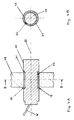
- Fig. 4A which is a cross-sectional view, shows the arrangement of an output module 15 in a mould 18, the output module including a housing 17 in which a receiver is accommodated.
- Electric wires W provide a connection of the output module to a circuitry unit 11 (not shown in Fig. 4 , see Fig. 1 ).
- the circuitry unit 11 according to the second embodiment has the same function as that of the first embodiment, and a further description is therefore omitted.
- a porous material 21 is arranged at the circumferential surface of the output module 15 facing the opening in the mould 18 . More specifically, at the portion of the output module 15 facing the mould 18 a recessed portion 22 such as a groove is provided for accommodating a layer of a porous material 21.
- the recessed portion 22 extends in the circumferential direction around the output module 15, and the layer of the porous material 21 is accommodated in the recessed portion and also extends in the circumferential direction around the output module 15.
- Fig. 4B shows a cross-sectional view along the line B-B shown in Fig. 4A .
- the inner circle of the structure shown in Fig. 4B represents the output module 15 and having the recessed portion which results in a reduced diameter of the output module 15.
- the layer of the porous material 21 is arranged and represented in Fig. 4B as an annular portion in a range between the reduced diameter of the output module 15 and basically the maximum diameter thereof.
- the layer of the porous material 21 arranged on the recessed portion 22 of the output module 15 is adjacent to the inner surface of the opening in the mould 18, and the recessed portion 22 filled with the porous material 21 between the output module 15 and the mould 18 constitutes a venting channel 19 defined between the output module 15 and the mould 18 (opening).
- the present invention is however not limited to a complete filling of the recessed portion 22 of the output module 15 with the porous material 21, and this porous material 21 can also be inserted in or accommodated by the recessed portion in part, resulting in the arrangement of the porous material 21 in predetermined parts of the recessed portion 22.
- the recessed portion can be void of any filling material (other than air).
- the present invention is not limited to a ring-shaped cross-sectional area of the venting channel 19 defined according to Figs. 4A and 4B between the output module 15 and the opening of the mould 18.
- any suitable cross-sectional area of the output module 15 accommodating the receiver 16 and of the form and shape of the recessed portion 22 can be implemented, resulting in a corresponding opening in the mould 18 so that the recessed portion, possibly including partly or completely the porous material 21, properly fits into the opening of the mould 18.
- One alternative is e.g. a helical groove in the outer surface of the output module allowing air to propagate from the enclosed volume to the outside.
- the groove can likewise be filled with a material to control its acoustic propagation properties.
- the preferably ring-shaped venting channel 19 according to the second embodiment shown in Figs. 4A and 4B extends along a longitudinal axis 20 of the output module 15.
- the porous material 21 has a filtering function.
- the porous material 21 can be replaced when the output module 15 is removed from the mould 18 for maintenance purposes. Due to the fact that the dimensions of the output module 15 can be kept small despite the fact that an effective venting channel 19 is provided, the output module 15 (including the receiver 16) can be inserted in a small mould 18, such as a micro mould.
- the porous material porous filter, porous layer which is inserted in a recessed portion around the receiver module (at the outer surface of the housing 17) is therefore useful for obtaining high frequency attenuation in a predetermined manner.
Landscapes
- Engineering & Computer Science (AREA)
- Manufacturing & Machinery (AREA)
- Health & Medical Sciences (AREA)
- General Health & Medical Sciences (AREA)
- Neurosurgery (AREA)
- Otolaryngology (AREA)
- Physics & Mathematics (AREA)
- Acoustics & Sound (AREA)
- Signal Processing (AREA)
- Headphones And Earphones (AREA)
Priority Applications (4)
| Application Number | Priority Date | Filing Date | Title |
|---|---|---|---|
| EP07124085.7A EP2076064B1 (fr) | 2007-12-27 | 2007-12-27 | Appareil auditif comportant un moulage et un module de sortie |
| DK07124085.7T DK2076064T3 (en) | 2007-12-27 | 2007-12-27 | Hearing device comprising a mold and an output module |
| US12/338,567 US8630434B2 (en) | 2007-12-27 | 2008-12-18 | Hearing device comprising a mould and an output module |
| CNA2008101865643A CN101483800A (zh) | 2007-12-27 | 2008-12-25 | 包括耳模和输出模块的听力设备 |
Applications Claiming Priority (1)
| Application Number | Priority Date | Filing Date | Title |
|---|---|---|---|
| EP07124085.7A EP2076064B1 (fr) | 2007-12-27 | 2007-12-27 | Appareil auditif comportant un moulage et un module de sortie |
Publications (2)
| Publication Number | Publication Date |
|---|---|
| EP2076064A1 true EP2076064A1 (fr) | 2009-07-01 |
| EP2076064B1 EP2076064B1 (fr) | 2017-04-26 |
Family
ID=39083295
Family Applications (1)
| Application Number | Title | Priority Date | Filing Date |
|---|---|---|---|
| EP07124085.7A Not-in-force EP2076064B1 (fr) | 2007-12-27 | 2007-12-27 | Appareil auditif comportant un moulage et un module de sortie |
Country Status (4)
| Country | Link |
|---|---|
| US (1) | US8630434B2 (fr) |
| EP (1) | EP2076064B1 (fr) |
| CN (1) | CN101483800A (fr) |
| DK (1) | DK2076064T3 (fr) |
Families Citing this family (11)
| Publication number | Priority date | Publication date | Assignee | Title |
|---|---|---|---|---|
| JP5543929B2 (ja) * | 2009-02-05 | 2014-07-09 | 国立大学法人大阪大学 | 入力デバイス、ウェアラブルコンピュータ、及び入力方法 |
| US8340335B1 (en) * | 2009-08-18 | 2012-12-25 | iHear Medical, Inc. | Hearing device with semipermanent canal receiver module |
| EP2495991A1 (fr) * | 2011-03-04 | 2012-09-05 | Knowles Electronics Asia PTE. Ltd. | Conditionnement de volume acoustique augmentant les matériaux pour dispositifs de haut-parleur |
| EP2595413B1 (fr) * | 2011-11-17 | 2015-07-01 | Oticon A/S | Fixage d'appareils auditifs |
| US10492009B2 (en) | 2012-05-07 | 2019-11-26 | Starkey Laboratories, Inc. | Hearing aid with distributed processing in ear piece |
| US9579745B2 (en) * | 2012-08-29 | 2017-02-28 | Apple Inc. | Systems and methods for enhancing performance of a microphone |
| WO2016025826A1 (fr) | 2014-08-15 | 2016-02-18 | iHear Medical, Inc. | Dispositif auditif intracanal et procédés pour la télécommande sans fil d'un appareil |
| US9769577B2 (en) | 2014-08-22 | 2017-09-19 | iHear Medical, Inc. | Hearing device and methods for wireless remote control of an appliance |
| US20160134742A1 (en) | 2014-11-11 | 2016-05-12 | iHear Medical, Inc. | Subscription-based wireless service for a canal hearing device |
| US10264370B2 (en) | 2015-04-20 | 2019-04-16 | Oticon A/S | Hearing device configured to be placed in the ear canal of a user |
| DE102020202725B4 (de) | 2020-03-03 | 2022-11-17 | Sivantos Pte. Ltd. | Binaurales Hörsystem mit zwei im oder am Ohr des Nutzers getragenen Hörinstrumenten sowie Verfahren zum Betrieb eines solchen Hörsystems |
Citations (4)
| Publication number | Priority date | Publication date | Assignee | Title |
|---|---|---|---|---|
| DE3927797A1 (de) | 1989-08-23 | 1991-02-28 | Toepholm & Westermann | Im-ohr-hoergeraet mit schall-ausgleichskanal |
| WO2000076271A1 (fr) * | 1999-06-08 | 2000-12-14 | Insonus Medical, Inc. | Dispositif de correction auditive a installation dans le conduit, pour un port prolonge |
| US20070071265A1 (en) * | 1999-05-05 | 2007-03-29 | Leedom Marvin A | Disposable modular hearing aid |
| WO2007038712A2 (fr) * | 2005-09-27 | 2007-04-05 | Insound Medical, Inc. | Element de retenue d'isolation destine a des dispositifs auditifs a port prolonge |
Family Cites Families (5)
| Publication number | Priority date | Publication date | Assignee | Title |
|---|---|---|---|---|
| WO2001026421A1 (fr) * | 1999-10-06 | 2001-04-12 | Sarnoff Corporation | Tetes d'appareil auditif jetables |
| DE10204894A1 (de) * | 2002-02-06 | 2003-08-21 | Siemens Audiologische Technik | Im Ohr tragbares Hörhilfegerät oder Hörhilfegerät mit im Ohr tragbarer Otoplastik |
| US7236605B2 (en) * | 2003-12-05 | 2007-06-26 | Hearing Components, Inc. | User disposable sleeve for use within the ear canal |
| JP4966304B2 (ja) * | 2005-08-01 | 2012-07-04 | ジーエヌ リザウンド エー/エス | 短い通気孔を有する開放耳当てを備えた聴取装置 |
| DE102006029726A1 (de) * | 2006-06-28 | 2008-01-10 | Siemens Audiologische Technik Gmbh | Hörhilfsgerät |
-
2007
- 2007-12-27 DK DK07124085.7T patent/DK2076064T3/en active
- 2007-12-27 EP EP07124085.7A patent/EP2076064B1/fr not_active Not-in-force
-
2008
- 2008-12-18 US US12/338,567 patent/US8630434B2/en active Active
- 2008-12-25 CN CNA2008101865643A patent/CN101483800A/zh active Pending
Patent Citations (4)
| Publication number | Priority date | Publication date | Assignee | Title |
|---|---|---|---|---|
| DE3927797A1 (de) | 1989-08-23 | 1991-02-28 | Toepholm & Westermann | Im-ohr-hoergeraet mit schall-ausgleichskanal |
| US20070071265A1 (en) * | 1999-05-05 | 2007-03-29 | Leedom Marvin A | Disposable modular hearing aid |
| WO2000076271A1 (fr) * | 1999-06-08 | 2000-12-14 | Insonus Medical, Inc. | Dispositif de correction auditive a installation dans le conduit, pour un port prolonge |
| WO2007038712A2 (fr) * | 2005-09-27 | 2007-04-05 | Insound Medical, Inc. | Element de retenue d'isolation destine a des dispositifs auditifs a port prolonge |
Also Published As
| Publication number | Publication date |
|---|---|
| CN101483800A (zh) | 2009-07-15 |
| DK2076064T3 (en) | 2017-07-17 |
| US8630434B2 (en) | 2014-01-14 |
| US20090169039A1 (en) | 2009-07-02 |
| EP2076064B1 (fr) | 2017-04-26 |
Similar Documents
| Publication | Publication Date | Title |
|---|---|---|
| EP2076064B1 (fr) | Appareil auditif comportant un moulage et un module de sortie | |
| EP2432254B1 (fr) | Instrument auditif | |
| US7844065B2 (en) | Hearing instrument | |
| JP5764199B2 (ja) | 補聴器 | |
| US8625831B2 (en) | Hearing aid earpiece and a method of manufacturing a hearing aid earpiece | |
| US20120257774A1 (en) | Ear plug for a hearing aid and a hearing aid | |
| EP2840808B1 (fr) | Tube acoustique et embout d'oreille pour dispositif d'aide auditive à porter derrière l'oreille | |
| EP3025511B1 (fr) | Dispositif auditif à réponse basse fréquence améliorée et procédé de fabrication dudit dispositif auditif | |
| WO2023241661A1 (fr) | Élément acoustique, dispositif acoustique et procédé de préparation d'un élément acoustique | |
| US11178497B2 (en) | In-ear receiver | |
| WO2009100559A2 (fr) | Appareil auditif |
Legal Events
| Date | Code | Title | Description |
|---|---|---|---|
| PUAI | Public reference made under article 153(3) epc to a published international application that has entered the european phase |
Free format text: ORIGINAL CODE: 0009012 |
|
| AK | Designated contracting states |
Kind code of ref document: A1 Designated state(s): AT BE BG CH CY CZ DE DK EE ES FI FR GB GR HU IE IS IT LI LT LU LV MC MT NL PL PT RO SE SI SK TR |
|
| AX | Request for extension of the european patent |
Extension state: AL BA HR MK RS |
|
| 17P | Request for examination filed |
Effective date: 20090707 |
|
| 17Q | First examination report despatched |
Effective date: 20090731 |
|
| AKX | Designation fees paid |
Designated state(s): AT BE BG CH CY CZ DE DK EE ES FI FR GB GR HU IE IS IT LI LT LU LV MC MT NL PL PT RO SE SI SK TR |
|
| GRAP | Despatch of communication of intention to grant a patent |
Free format text: ORIGINAL CODE: EPIDOSNIGR1 |
|
| INTG | Intention to grant announced |
Effective date: 20161121 |
|
| GRAS | Grant fee paid |
Free format text: ORIGINAL CODE: EPIDOSNIGR3 |
|
| GRAA | (expected) grant |
Free format text: ORIGINAL CODE: 0009210 |
|
| AK | Designated contracting states |
Kind code of ref document: B1 Designated state(s): AT BE BG CH CY CZ DE DK EE ES FI FR GB GR HU IE IS IT LI LT LU LV MC MT NL PL PT RO SE SI SK TR |
|
| REG | Reference to a national code |
Ref country code: GB Ref legal event code: FG4D |
|
| REG | Reference to a national code |
Ref country code: CH Ref legal event code: EP |
|
| REG | Reference to a national code |
Ref country code: AT Ref legal event code: REF Ref document number: 888821 Country of ref document: AT Kind code of ref document: T Effective date: 20170515 |
|
| REG | Reference to a national code |
Ref country code: IE Ref legal event code: FG4D |
|
| REG | Reference to a national code |
Ref country code: DE Ref legal event code: R096 Ref document number: 602007050747 Country of ref document: DE |
|
| REG | Reference to a national code |
Ref country code: DK Ref legal event code: T3 Effective date: 20170706 |
|
| REG | Reference to a national code |
Ref country code: NL Ref legal event code: MP Effective date: 20170426 |
|
| REG | Reference to a national code |
Ref country code: LT Ref legal event code: MG4D |
|
| REG | Reference to a national code |
Ref country code: AT Ref legal event code: MK05 Ref document number: 888821 Country of ref document: AT Kind code of ref document: T Effective date: 20170426 |
|
| PG25 | Lapsed in a contracting state [announced via postgrant information from national office to epo] |
Ref country code: NL Free format text: LAPSE BECAUSE OF FAILURE TO SUBMIT A TRANSLATION OF THE DESCRIPTION OR TO PAY THE FEE WITHIN THE PRESCRIBED TIME-LIMIT Effective date: 20170426 |
|
| PG25 | Lapsed in a contracting state [announced via postgrant information from national office to epo] |
Ref country code: AT Free format text: LAPSE BECAUSE OF FAILURE TO SUBMIT A TRANSLATION OF THE DESCRIPTION OR TO PAY THE FEE WITHIN THE PRESCRIBED TIME-LIMIT Effective date: 20170426 Ref country code: ES Free format text: LAPSE BECAUSE OF FAILURE TO SUBMIT A TRANSLATION OF THE DESCRIPTION OR TO PAY THE FEE WITHIN THE PRESCRIBED TIME-LIMIT Effective date: 20170426 Ref country code: FI Free format text: LAPSE BECAUSE OF FAILURE TO SUBMIT A TRANSLATION OF THE DESCRIPTION OR TO PAY THE FEE WITHIN THE PRESCRIBED TIME-LIMIT Effective date: 20170426 Ref country code: GR Free format text: LAPSE BECAUSE OF FAILURE TO SUBMIT A TRANSLATION OF THE DESCRIPTION OR TO PAY THE FEE WITHIN THE PRESCRIBED TIME-LIMIT Effective date: 20170727 Ref country code: LT Free format text: LAPSE BECAUSE OF FAILURE TO SUBMIT A TRANSLATION OF THE DESCRIPTION OR TO PAY THE FEE WITHIN THE PRESCRIBED TIME-LIMIT Effective date: 20170426 |
|
| PG25 | Lapsed in a contracting state [announced via postgrant information from national office to epo] |
Ref country code: PL Free format text: LAPSE BECAUSE OF FAILURE TO SUBMIT A TRANSLATION OF THE DESCRIPTION OR TO PAY THE FEE WITHIN THE PRESCRIBED TIME-LIMIT Effective date: 20170426 Ref country code: LV Free format text: LAPSE BECAUSE OF FAILURE TO SUBMIT A TRANSLATION OF THE DESCRIPTION OR TO PAY THE FEE WITHIN THE PRESCRIBED TIME-LIMIT Effective date: 20170426 Ref country code: IS Free format text: LAPSE BECAUSE OF FAILURE TO SUBMIT A TRANSLATION OF THE DESCRIPTION OR TO PAY THE FEE WITHIN THE PRESCRIBED TIME-LIMIT Effective date: 20170826 Ref country code: SE Free format text: LAPSE BECAUSE OF FAILURE TO SUBMIT A TRANSLATION OF THE DESCRIPTION OR TO PAY THE FEE WITHIN THE PRESCRIBED TIME-LIMIT Effective date: 20170426 Ref country code: BG Free format text: LAPSE BECAUSE OF FAILURE TO SUBMIT A TRANSLATION OF THE DESCRIPTION OR TO PAY THE FEE WITHIN THE PRESCRIBED TIME-LIMIT Effective date: 20170726 |
|
| REG | Reference to a national code |
Ref country code: FR Ref legal event code: PLFP Year of fee payment: 11 |
|
| REG | Reference to a national code |
Ref country code: DE Ref legal event code: R097 Ref document number: 602007050747 Country of ref document: DE |
|
| PG25 | Lapsed in a contracting state [announced via postgrant information from national office to epo] |
Ref country code: SK Free format text: LAPSE BECAUSE OF FAILURE TO SUBMIT A TRANSLATION OF THE DESCRIPTION OR TO PAY THE FEE WITHIN THE PRESCRIBED TIME-LIMIT Effective date: 20170426 Ref country code: CZ Free format text: LAPSE BECAUSE OF FAILURE TO SUBMIT A TRANSLATION OF THE DESCRIPTION OR TO PAY THE FEE WITHIN THE PRESCRIBED TIME-LIMIT Effective date: 20170426 Ref country code: RO Free format text: LAPSE BECAUSE OF FAILURE TO SUBMIT A TRANSLATION OF THE DESCRIPTION OR TO PAY THE FEE WITHIN THE PRESCRIBED TIME-LIMIT Effective date: 20170426 Ref country code: EE Free format text: LAPSE BECAUSE OF FAILURE TO SUBMIT A TRANSLATION OF THE DESCRIPTION OR TO PAY THE FEE WITHIN THE PRESCRIBED TIME-LIMIT Effective date: 20170426 |
|
| PGFP | Annual fee paid to national office [announced via postgrant information from national office to epo] |
Ref country code: DK Payment date: 20171205 Year of fee payment: 11 Ref country code: FR Payment date: 20171206 Year of fee payment: 11 Ref country code: DE Payment date: 20171211 Year of fee payment: 11 |
|
| PG25 | Lapsed in a contracting state [announced via postgrant information from national office to epo] |
Ref country code: IT Free format text: LAPSE BECAUSE OF FAILURE TO SUBMIT A TRANSLATION OF THE DESCRIPTION OR TO PAY THE FEE WITHIN THE PRESCRIBED TIME-LIMIT Effective date: 20170426 |
|
| PGFP | Annual fee paid to national office [announced via postgrant information from national office to epo] |
Ref country code: CH Payment date: 20171213 Year of fee payment: 11 Ref country code: GB Payment date: 20171205 Year of fee payment: 11 |
|
| PLBE | No opposition filed within time limit |
Free format text: ORIGINAL CODE: 0009261 |
|
| STAA | Information on the status of an ep patent application or granted ep patent |
Free format text: STATUS: NO OPPOSITION FILED WITHIN TIME LIMIT |
|
| 26N | No opposition filed |
Effective date: 20180129 |
|
| PG25 | Lapsed in a contracting state [announced via postgrant information from national office to epo] |
Ref country code: SI Free format text: LAPSE BECAUSE OF FAILURE TO SUBMIT A TRANSLATION OF THE DESCRIPTION OR TO PAY THE FEE WITHIN THE PRESCRIBED TIME-LIMIT Effective date: 20170426 |
|
| REG | Reference to a national code |
Ref country code: IE Ref legal event code: MM4A |
|
| PG25 | Lapsed in a contracting state [announced via postgrant information from national office to epo] |
Ref country code: MT Free format text: LAPSE BECAUSE OF NON-PAYMENT OF DUE FEES Effective date: 20171227 Ref country code: LU Free format text: LAPSE BECAUSE OF NON-PAYMENT OF DUE FEES Effective date: 20171227 |
|
| REG | Reference to a national code |
Ref country code: BE Ref legal event code: MM Effective date: 20171231 |
|
| PG25 | Lapsed in a contracting state [announced via postgrant information from national office to epo] |
Ref country code: IE Free format text: LAPSE BECAUSE OF NON-PAYMENT OF DUE FEES Effective date: 20171227 |
|
| PG25 | Lapsed in a contracting state [announced via postgrant information from national office to epo] |
Ref country code: BE Free format text: LAPSE BECAUSE OF NON-PAYMENT OF DUE FEES Effective date: 20171231 |
|
| PG25 | Lapsed in a contracting state [announced via postgrant information from national office to epo] |
Ref country code: MC Free format text: LAPSE BECAUSE OF FAILURE TO SUBMIT A TRANSLATION OF THE DESCRIPTION OR TO PAY THE FEE WITHIN THE PRESCRIBED TIME-LIMIT Effective date: 20170426 Ref country code: HU Free format text: LAPSE BECAUSE OF FAILURE TO SUBMIT A TRANSLATION OF THE DESCRIPTION OR TO PAY THE FEE WITHIN THE PRESCRIBED TIME-LIMIT; INVALID AB INITIO Effective date: 20071227 |
|
| REG | Reference to a national code |
Ref country code: DE Ref legal event code: R119 Ref document number: 602007050747 Country of ref document: DE |
|
| REG | Reference to a national code |
Ref country code: DK Ref legal event code: EBP Effective date: 20181231 |
|
| REG | Reference to a national code |
Ref country code: CH Ref legal event code: PL |
|
| GBPC | Gb: european patent ceased through non-payment of renewal fee |
Effective date: 20181227 |
|
| PG25 | Lapsed in a contracting state [announced via postgrant information from national office to epo] |
Ref country code: FR Free format text: LAPSE BECAUSE OF NON-PAYMENT OF DUE FEES Effective date: 20181231 Ref country code: CY Free format text: LAPSE BECAUSE OF NON-PAYMENT OF DUE FEES Effective date: 20170426 Ref country code: DE Free format text: LAPSE BECAUSE OF NON-PAYMENT OF DUE FEES Effective date: 20190702 |
|
| PG25 | Lapsed in a contracting state [announced via postgrant information from national office to epo] |
Ref country code: LI Free format text: LAPSE BECAUSE OF NON-PAYMENT OF DUE FEES Effective date: 20181231 Ref country code: GB Free format text: LAPSE BECAUSE OF NON-PAYMENT OF DUE FEES Effective date: 20181227 Ref country code: CH Free format text: LAPSE BECAUSE OF NON-PAYMENT OF DUE FEES Effective date: 20181231 |
|
| PG25 | Lapsed in a contracting state [announced via postgrant information from national office to epo] |
Ref country code: DK Free format text: LAPSE BECAUSE OF NON-PAYMENT OF DUE FEES Effective date: 20181231 |
|
| PG25 | Lapsed in a contracting state [announced via postgrant information from national office to epo] |
Ref country code: TR Free format text: LAPSE BECAUSE OF FAILURE TO SUBMIT A TRANSLATION OF THE DESCRIPTION OR TO PAY THE FEE WITHIN THE PRESCRIBED TIME-LIMIT Effective date: 20170426 |
|
| PG25 | Lapsed in a contracting state [announced via postgrant information from national office to epo] |
Ref country code: PT Free format text: LAPSE BECAUSE OF FAILURE TO SUBMIT A TRANSLATION OF THE DESCRIPTION OR TO PAY THE FEE WITHIN THE PRESCRIBED TIME-LIMIT Effective date: 20170426 |