EP2075862A1 - Electrode for electrochemical device and electrochemical device - Google Patents
Electrode for electrochemical device and electrochemical device Download PDFInfo
- Publication number
- EP2075862A1 EP2075862A1 EP08021675A EP08021675A EP2075862A1 EP 2075862 A1 EP2075862 A1 EP 2075862A1 EP 08021675 A EP08021675 A EP 08021675A EP 08021675 A EP08021675 A EP 08021675A EP 2075862 A1 EP2075862 A1 EP 2075862A1
- Authority
- EP
- European Patent Office
- Prior art keywords
- collector
- electrode
- lead
- longitudinal direction
- opt
- Prior art date
- Legal status (The legal status is an assumption and is not a legal conclusion. Google has not performed a legal analysis and makes no representation as to the accuracy of the status listed.)
- Granted
Links
Images




Classifications
-
- H—ELECTRICITY
- H01—ELECTRIC ELEMENTS
- H01M—PROCESSES OR MEANS, e.g. BATTERIES, FOR THE DIRECT CONVERSION OF CHEMICAL ENERGY INTO ELECTRICAL ENERGY
- H01M4/00—Electrodes
- H01M4/02—Electrodes composed of, or comprising, active material
- H01M4/64—Carriers or collectors
- H01M4/66—Selection of materials
- H01M4/661—Metal or alloys, e.g. alloy coatings
-
- H—ELECTRICITY
- H01—ELECTRIC ELEMENTS
- H01G—CAPACITORS; CAPACITORS, RECTIFIERS, DETECTORS, SWITCHING DEVICES, LIGHT-SENSITIVE OR TEMPERATURE-SENSITIVE DEVICES OF THE ELECTROLYTIC TYPE
- H01G11/00—Hybrid capacitors, i.e. capacitors having different positive and negative electrodes; Electric double-layer [EDL] capacitors; Processes for the manufacture thereof or of parts thereof
- H01G11/66—Current collectors
- H01G11/72—Current collectors specially adapted for integration in multiple or stacked hybrid or EDL capacitors
-
- H—ELECTRICITY
- H01—ELECTRIC ELEMENTS
- H01G—CAPACITORS; CAPACITORS, RECTIFIERS, DETECTORS, SWITCHING DEVICES, LIGHT-SENSITIVE OR TEMPERATURE-SENSITIVE DEVICES OF THE ELECTROLYTIC TYPE
- H01G11/00—Hybrid capacitors, i.e. capacitors having different positive and negative electrodes; Electric double-layer [EDL] capacitors; Processes for the manufacture thereof or of parts thereof
- H01G11/74—Terminals, e.g. extensions of current collectors
-
- H—ELECTRICITY
- H01—ELECTRIC ELEMENTS
- H01G—CAPACITORS; CAPACITORS, RECTIFIERS, DETECTORS, SWITCHING DEVICES, LIGHT-SENSITIVE OR TEMPERATURE-SENSITIVE DEVICES OF THE ELECTROLYTIC TYPE
- H01G9/00—Electrolytic capacitors, rectifiers, detectors, switching devices, light-sensitive or temperature-sensitive devices; Processes of their manufacture
- H01G9/004—Details
- H01G9/008—Terminals
-
- H—ELECTRICITY
- H01—ELECTRIC ELEMENTS
- H01G—CAPACITORS; CAPACITORS, RECTIFIERS, DETECTORS, SWITCHING DEVICES, LIGHT-SENSITIVE OR TEMPERATURE-SENSITIVE DEVICES OF THE ELECTROLYTIC TYPE
- H01G9/00—Electrolytic capacitors, rectifiers, detectors, switching devices, light-sensitive or temperature-sensitive devices; Processes of their manufacture
- H01G9/004—Details
- H01G9/04—Electrodes or formation of dielectric layers thereon
- H01G9/06—Mounting in containers
-
- H—ELECTRICITY
- H01—ELECTRIC ELEMENTS
- H01G—CAPACITORS; CAPACITORS, RECTIFIERS, DETECTORS, SWITCHING DEVICES, LIGHT-SENSITIVE OR TEMPERATURE-SENSITIVE DEVICES OF THE ELECTROLYTIC TYPE
- H01G9/00—Electrolytic capacitors, rectifiers, detectors, switching devices, light-sensitive or temperature-sensitive devices; Processes of their manufacture
- H01G9/15—Solid electrolytic capacitors
- H01G9/151—Solid electrolytic capacitors with wound foil electrodes
-
- H—ELECTRICITY
- H01—ELECTRIC ELEMENTS
- H01M—PROCESSES OR MEANS, e.g. BATTERIES, FOR THE DIRECT CONVERSION OF CHEMICAL ENERGY INTO ELECTRICAL ENERGY
- H01M10/00—Secondary cells; Manufacture thereof
- H01M10/04—Construction or manufacture in general
- H01M10/0431—Cells with wound or folded electrodes
-
- H—ELECTRICITY
- H01—ELECTRIC ELEMENTS
- H01M—PROCESSES OR MEANS, e.g. BATTERIES, FOR THE DIRECT CONVERSION OF CHEMICAL ENERGY INTO ELECTRICAL ENERGY
- H01M50/00—Constructional details or processes of manufacture of the non-active parts of electrochemical cells other than fuel cells, e.g. hybrid cells
- H01M50/50—Current conducting connections for cells or batteries
- H01M50/531—Electrode connections inside a battery casing
- H01M50/533—Electrode connections inside a battery casing characterised by the shape of the leads or tabs
-
- H—ELECTRICITY
- H01—ELECTRIC ELEMENTS
- H01M—PROCESSES OR MEANS, e.g. BATTERIES, FOR THE DIRECT CONVERSION OF CHEMICAL ENERGY INTO ELECTRICAL ENERGY
- H01M50/00—Constructional details or processes of manufacture of the non-active parts of electrochemical cells other than fuel cells, e.g. hybrid cells
- H01M50/50—Current conducting connections for cells or batteries
- H01M50/531—Electrode connections inside a battery casing
- H01M50/536—Electrode connections inside a battery casing characterised by the method of fixing the leads to the electrodes, e.g. by welding
-
- H—ELECTRICITY
- H01—ELECTRIC ELEMENTS
- H01M—PROCESSES OR MEANS, e.g. BATTERIES, FOR THE DIRECT CONVERSION OF CHEMICAL ENERGY INTO ELECTRICAL ENERGY
- H01M50/00—Constructional details or processes of manufacture of the non-active parts of electrochemical cells other than fuel cells, e.g. hybrid cells
- H01M50/50—Current conducting connections for cells or batteries
- H01M50/531—Electrode connections inside a battery casing
- H01M50/538—Connection of several leads or tabs of wound or folded electrode stacks
-
- Y—GENERAL TAGGING OF NEW TECHNOLOGICAL DEVELOPMENTS; GENERAL TAGGING OF CROSS-SECTIONAL TECHNOLOGIES SPANNING OVER SEVERAL SECTIONS OF THE IPC; TECHNICAL SUBJECTS COVERED BY FORMER USPC CROSS-REFERENCE ART COLLECTIONS [XRACs] AND DIGESTS
- Y02—TECHNOLOGIES OR APPLICATIONS FOR MITIGATION OR ADAPTATION AGAINST CLIMATE CHANGE
- Y02E—REDUCTION OF GREENHOUSE GAS [GHG] EMISSIONS, RELATED TO ENERGY GENERATION, TRANSMISSION OR DISTRIBUTION
- Y02E60/00—Enabling technologies; Technologies with a potential or indirect contribution to GHG emissions mitigation
- Y02E60/10—Energy storage using batteries
-
- Y—GENERAL TAGGING OF NEW TECHNOLOGICAL DEVELOPMENTS; GENERAL TAGGING OF CROSS-SECTIONAL TECHNOLOGIES SPANNING OVER SEVERAL SECTIONS OF THE IPC; TECHNICAL SUBJECTS COVERED BY FORMER USPC CROSS-REFERENCE ART COLLECTIONS [XRACs] AND DIGESTS
- Y02—TECHNOLOGIES OR APPLICATIONS FOR MITIGATION OR ADAPTATION AGAINST CLIMATE CHANGE
- Y02E—REDUCTION OF GREENHOUSE GAS [GHG] EMISSIONS, RELATED TO ENERGY GENERATION, TRANSMISSION OR DISTRIBUTION
- Y02E60/00—Enabling technologies; Technologies with a potential or indirect contribution to GHG emissions mitigation
- Y02E60/13—Energy storage using capacitors
-
- Y—GENERAL TAGGING OF NEW TECHNOLOGICAL DEVELOPMENTS; GENERAL TAGGING OF CROSS-SECTIONAL TECHNOLOGIES SPANNING OVER SEVERAL SECTIONS OF THE IPC; TECHNICAL SUBJECTS COVERED BY FORMER USPC CROSS-REFERENCE ART COLLECTIONS [XRACs] AND DIGESTS
- Y02—TECHNOLOGIES OR APPLICATIONS FOR MITIGATION OR ADAPTATION AGAINST CLIMATE CHANGE
- Y02P—CLIMATE CHANGE MITIGATION TECHNOLOGIES IN THE PRODUCTION OR PROCESSING OF GOODS
- Y02P70/00—Climate change mitigation technologies in the production process for final industrial or consumer products
- Y02P70/50—Manufacturing or production processes characterised by the final manufactured product
Definitions
- the present invention relates to an electrode for electrochemical devices, and to an electrochemical device.
- Spirally wound electrochemical devices are formed by winding electrodes in the longitudinal direction, the electrodes being obtained by forming active material layers on an elongated collector.
- the collector is provided with a plurality of leads, spaced apart from each other, in the longitudinal direction of the collector, in order to suppress heat generation, polarization and the like that result from concentration of large currents (see, for instance, Japanese Patent Application Laid-open Nos. H7-192717 , H11-283882 , H11-283883 , H11-317218 , 2000-106167 , 2000-182656 , 2000-110453 , 2006-260892 and 2006-286404 ).
- the electrode for an electrochemical device comprises an elongated collector, a lead provided halfway along a longitudinal direction of the collector, and an active material layer provided on the collector.
- L a (m) is a distance from one end of the collector, in the longitudinal direction, up to said lead
- L b (m) is a distance from the other end of the collector, in the longitudinal direction, up to the lead
- ⁇ ( ⁇ m) is a resistivity of the collector at 25°C, where L opt (m) being 1.9 ⁇ 10 6 ⁇ , the L a (m) and L b (m) are from 0.95 L opt to 1.05 L opt respectively.
- Another electrode for an electrochemical device comprises an elongated collector, n leads (n being an integer equal to 2 or greater) provided spaced apart from each other in the collector, in a longitudinal direction of the collector, and an active material layer provided on the collector.
- L a (m) is a distance from one end of the collector, in the longitudinal direction, up to a lead closest to the one end
- L b (m) is a distance from the other end of the collector, in the longitudinal direction, up to a lead closest to the other end
- L 1 , L 2 , ..., L n-1 (m) are distances between adjacent leads
- ⁇ ( ⁇ m) is a resistivity of the collector at 25°C
- the electrochemical device according to the present invention comprises a pair of electrodes, both electrodes being the above-described electrode for electrochemical devices.
- Such an electrode for electrochemical devices affords an electrochemical device having low impedance and low leakage current.
- Fig. 1 is a schematic perspective-view diagram of an electrode for electrochemical devices according to a first embodiment
- the electrode for electrochemical devices 10 comprises mainly a collector 12, active material layers 13A, 13C containing an active material, and a lead 15.
- the collector 12 is a conductive member in the form of a rectangular elongated plate.
- the material of the collector is preferably a metallic material, such as copper, aluminum or nickel.
- the electric resistivity p of copper, aluminum and nickel are 1.68 ⁇ 10 -8 ⁇ m, 2.65 ⁇ 10 -8 ⁇ m, 6.99 ⁇ 10 -8 ⁇ m, respectively.
- the thickness of the collector is not particularly limited, and may range from 10 to 50 ⁇ m.
- the length L 0 in the longitudinal direction and the length W 0 in the direction (width direction) perpendicular to the longitudinal direction are not particularly limited.
- the length L 0 in the longitudinal direction may range, for instance, from 80 to 150 mm, while the length W 0 in the width direction may range, for instance, from 12 to 16 mm.
- the aspect ratio (L 0 /W 0 ) of the collector is preferably 5 to 10, more preferably about 7.0.
- the lead 15 is a conductive member that plays the role of current input terminal in the collector 12.
- the lead 15 is shaped as a rectangular plate, the longitudinal direction of the lead 15 being perpendicular to the longitudinal direction of the collector 12.
- one end face 15d of the lead 15 in the longitudinal direction extends up to one side face 12d of the collector 12 in the direction (width direction) perpendicular to the longitudinal direction of the collector 12, while the other end face 15c of the lead 15, in the longitudinal direction, extends beyond the other side face 12c of the collector 12 in a direction (width direction) that is perpendicular to the longitudinal direction of the collector 12.
- the thickness of the lead 15 is not particularly limited, and may be for instance similar to that of the collector 12.
- the length of the lead 15 in the longitudinal direction can be arbitrarily set in accordance with the way in which the lead is to be used, provided that the other end face 15c of the lead 15 protrudes beyond the side face 12c of the collector 12.
- the length A of the lead 15, in a direction perpendicular to the longitudinal direction of the lead 15, is best sufficiently shorter than the length L 0 of the collector 12 in the longitudinal direction of the latter.
- the lead 15 may protrude about 10 to 25 mm beyond the side face 12c of the collector 12, and the width A of the lead 15 may range, for instance, from 2 to 10 mm.
- the lead 15 and the collector 12 are fixed together and electrically connected by way of, for instance, a conductive adhesive, soldering or welding.
- Side faces 15a and 15b of the lead 15 extending in the longitudinal direction thereof are respectively parallel to end faces (one end, other end) 12a, 12b that are perpendicular to the longitudinal direction of the collector 12.
- the active material layers 13A, 13C which are layers containing an active material, are provided on the front and rear faces, respectively, of the collector 12. Specifically, the active material layer 13C is provided over substantially the entire surface of the collector 12 where the lead 15 is not provided. Meanwhile, the active material layers 13A, 13A are dividedly provided on the surface of the collector 12 on which the lead 15 is provided, at portions other than the portion at which the lead 15 is provided.
- the active material layers 13A, 13C comprise preferably an active material and a binder. More preferably, the active material layers 13A, 13C comprise a conduction enhancer.
- active materials can be used as active materials for positive electrodes of lithium-ion secondary batteries, so long as the active material is capable of storing and releasing lithium ions, desorbing and intercalating lithium ions, and allows reversible doping and dedoping of lithium ions and counter anions of lithium ions (for instance, ClO 4 - ).
- the active material may be, for instance, a lithium-containing metal oxide.
- lithium-containing metal oxides include, for instance, a lithium oxide comprising at least one metal selected from the group consisting of Co, Ni and Mn, such as LiMO 2 (wherein M denotes Co, Ni or Mn) or LiCo x Ni 1-x O 2 , LiMn 2 O 4 and LiCo x Ni y Mn 1-x-y O 2 (wherein x and y are greater than 0 and smaller than 1), lithium vanadium compound (LiV 2 O 5 ) or olivine-like LiMPO 4 (wherein M denotes Co, Ni, Mn or Fe).
- LiMO 2 wherein M denotes Co, Ni or Mn
- LiCo x Ni 1-x O 2 , LiMn 2 O 4 and LiCo x Ni y Mn 1-x-y O 2 wherein x and y are greater than 0 and smaller than 1
- LiV 2 O 5 lithium vanadium compound
- olivine-like LiMPO 4 wherein M denotes Co, Ni, Mn or Fe
- active materials can be used as active materials for negative electrodes of lithium-ion secondary batteries, so long as the active material is capable of storing and releasing lithium ions, desorbing and intercalating lithium ions, and allows reversible doping and dedoping of lithium ions and counter anions of lithium ions (for instance, ClO 4 - ).
- Examples include, for instance, natural graphite, artificial graphite, mesocarbon microbeads, mesocarbon fibers (MCF), coke, glass-like carbon, carbonaceous materials such as fired products of organic compounds or the like, metals that can combine with lithium, such as Al, Si or Sn, or amorphous compounds having, as a main component, an oxide such as SiO 2 or SnO 2 .
- the electrodes for electric double-layer capacitors may be, for instance, various porous materials having electron conductivity. Suitable examples include, for instance, natural graphite, artificial graphite, mesocarbon microbeads, mesocarbon fibers (MCF), coke, glass-like carbon or carbonaceous materials such as fired products of organic compounds or the like.
- various bonding agents not particularly limited, provided that they can fix the above active material and, preferably also the conduction enhancer, to the collector.
- a fluororesin such as polyvinylidene fluoride (PVDF) or polytetrafluoroethylene (PTFE), or a mixture of styrene-butadiene rubber (SBR) with a water-soluble polymer (carboxymethylcellulose, polyvinyl alcohol, sodium polyacrylate, dextrin, gluten and the like).
- the conduction enhancer examples include, for instance, carbon black, metal micropowders of copper, nickel, stainless steel, iron or the like, mixtures of carbon materials and metal micropowders, or conductive oxides such as ITO.
- the conduction enhancer is a material added with a view to increasing the electron conductivity of the active material layers 13A, 13C.
- Acetylene black or carbon black can be suitably used as the conduction enhancer.
- the active material layers 13A, 13C Conventional methods may be used for forming the active material layers 13A, 13C. Although the active material layers 13A, 13C cover preferably most of the regions on the front and rear faces of the collector 12, the active material layers 13A, 13C need not necessarily cover all the regions, so that, for instance, the edges of the collector may remain uncovered.
- the distance L a between the lead 15 and an end face (one end) 12a of the collector 12 in the longitudinal direction, and the distance L b between the lead 15 and an end face (other end) 12b of the collector 12 in the longitudinal direction range both from 0.95L opt to 1.05L opt .
- L opt (m) 1.9 ⁇ 10 6 ⁇ , with p denoting the electric resistivity ( ⁇ m) of the collector 12 at 25°C.
- the distance L a and the distance L b can be thought of as the maximum distance covered by current in the collector 12 when current is supplied to, and discharged from, the active material layers 13A, 13C via the collector 12.
- L opt is the optimal value of this maximum distance, and is determined by the electric resistivity of the collector 12. In the present embodiment, therefore, the distance L a and the distance L b range from 95 to 105% of the optimal value L opt .
- An electrochemical device using such an electrode has enhanced characteristics, with extremely low impedance and leakage current values. Leakage current tends to increase when the distances L a and L b are smaller than 0.95L opt , while the impedance of the electrochemical device tends to increase when the distances L a and L b exceed 1.05L opt .
- the electrode for electrochemical devices 10 according to a second embodiment differs from the electrode for electrochemical devices according to the first embodiment in the shape of the lead 15, and thus only this feature will be explained.
- the end face 15d does not protrude up to the side face 12d of the collector 12, but is positioned over the surface 12e of the collector 12.
- Such an electrode for electrochemical devices 10 elicits the same effect as that of the first embodiment.
- the electrode for electrochemical devices 10 according to a third embodiment differs from the electrode for electrochemical devices according to the first embodiment in the shape of the lead 15, and thus only this feature will be explained.
- the lead 15 according to the third embodiment is not provided on the front face or rear face of the collector 12 but on the side face 12d of the collector 12.
- the active material layer 13A is not split but formed as a single unit, as is the case with the active material layer 13C.
- Such a lead 15 can be easily formed by cutting the collector 12 and the lead 15 out of a single conductive plate.
- Such an electrode for electrochemical devices 10 elicits the same effect as that of the first embodiment.
- an electrode for electrochemical devices 10 according to a fourth embodiment is explained next with reference to Fig. 4 .
- the length of the collector 12 in the longitudinal direction is longer than is the case in the electrode for electrochemical devices 10 of the first embodiment.
- n spaced-apart leads 15 in the longitudinal direction of the collector 12 are sequentially denoted as 15 1 , 15 2 ,..., 15 n , from the left of Fig. 4 .
- the distances L a and L b are defined in the same way as in the first embodiment and lie within the same ranges as prescribed in the first embodiment.
- L 1 denotes the distance between adjacent leads 15 1 , 15 2 , L 2 the distance between adjacent leads 15 2 , 15 3 , ... and L n-1 the distance between adjacent leads lead 15 n-1 , 15 n .
- the distances L 1 ,L 2 ,..., L n-1 are set so as to satisfy the condition that (L 1 /2),(L 2 /2),..., (L n-1 /2) range all from 0.95L opt to 1.05L opt .
- L 1 /2),(L 2 /2),..., (L n-1 /2) can be thought of as the maximum distances covered by the current in the collector 12 when current is supplied to, and charging is carried out in, the electrode 10.
- L opt is the optimal value of the largest distance. In the present embodiment, not only the distance L 1 and the distance L 2 but also (L 1 /2), (L 2 /2),..., (L n-1 /2) range all from 95% to 105% of the optimal value.
- Such an electrode for electrochemical devices 10 elicits the same effect as that of the first embodiment.
- the electrode of the second embodiment and the third embodiment may be provided as a plurality of electrodes, as in the fourth embodiment.
- Electrochemical device An electrochemical device using the above-described electrode 10 is explained next with reference to Figs. 5 and 6 .
- the electrochemical device explained herein uses the electrode for electrochemical devices of the first embodiment, but may equally use the electrode for electrochemical devices of any of the other embodiments.
- An electrochemical device 100 illustrated in Figs. 5 and 6 comprises a case 50, a wound body 30 and an electrolyte solution, omitted in the figure, held in the case and impregnating the wound body 30.
- the case 50 seals the wound body 30 and prevents intrusion of air and moisture into the interior of the case.
- the material used in the case 50 may be, for instance, a synthetic resin such as an epoxy resin, a laminate film in which a metal sheet of aluminum or the like is coated with a resin.
- the lead 15 of the wound body 30 protrudes out of the case 50.
- the electrolyte solution (not shown) fills the inner space of the case 50. Part of the electrolyte solution is contained in the interior of an electrode 10, an electrode 10 and a separator 20.
- the electrolyte solution used may be, for instance, a nonaqueous electrolyte solution in which a lithium salt is dissolved in an organic solvent.
- the lithium salt include, for instance, LiPF 6 , LiClO 4 , LiBF 4 , LiAsF 6 , LiCF 3 SO 3 , LiCF 3 CF 2 SO 3 , LiC(CF 3 SO 2 ) 3 , LiN(CF 3 SO 2 ) 2 , LiN(CF 3 CF 2 SO 2 ) 2 , LiN(CF 3 SO 2 )(C 4 F 9 SO 2 ) and LiN(CF 3 CF 2 CO) 2 .
- an electrolyte solution obtained by dissolving a quaternary ammonium salt such as tetraethylammonium tetrafluoroborate (TEA + BF 4 - ) or triethylmonomethylammonium tetrafluoroborate (TEMA + BF 4 - ) in an organic solvent.
- a quaternary ammonium salt such as tetraethylammonium tetrafluoroborate (TEA + BF 4 - ) or triethylmonomethylammonium tetrafluoroborate (TEMA + BF 4 - ) in an organic solvent.
- the electrolyte solution may form a gel through addition of a polymer or the like.
- organic solvent used in electrochemical devices may be employed as the organic solvent.
- Preferred examples thereof include, for instance, propylene carbonate, ethylene carbonate and diethyl carbonate. These organic solvents may be used singly or in mixtures of two or more at arbitrary mixing ratios.
- the wound body 30 is obtained by winding, in the longitudinal direction, a pair of the above-described electrodes for electrochemical devices 10, 10, in such a manner that a separator 20 is interposed between the electrodes for electrochemical devices 10, 10.
- a stack resulting from stacking an electrode 10/ separator 20 / electrode 10 / separator 20 is wound into a tubular form, starting form one end of the stack, to yield the wound body 30 illustrated in Fig. 5 , having a substantially tubular cross section.
- the above-described stack may be wound several times, starting from one end, while bending the stack into a flat form, to yield the wound body 30 illustrated in Fig. 6 , having a substantially oval cross section.
- the position at which the leads 15 protrude may lie in the same direction between electrodes, as illustrated in Fig. 6 , or in mutually opposing directions between electrodes, as illustrated in Fig. 5 .
- the separator 20 which provides electric insulation between the electrodes for electrochemical devices 10, 10, is an electrically insulating porous member.
- the material of the separator is not particularly limited, and there may be used various separator materials.
- electrically insulating porous members include, for instance, a stretched film of a single-layer or a multilayer film comprising polyethylene, polypropylene or a polyolefin, or of a mixture of the foregoing resins, or, alternatively, a fibrous nonwoven fabric comprising at least one constituent material selected from the group consisting of cellulose, polyester and polypropylene.
- the collector is shaped as an elongated plate, but the collector need only be a thin a long member, i.e. need only have a longitudinal direction.
- the collector may thus be shaped, for instance, as an elongated wire.
- the electrochemical device is not limited to batteries such as lithium-ion secondary batteries, or to electric double-layer capacitors, and may also be realized in, for instance, electrolytic capacitors or the like.
- Examples Electric double-layer capacitor (EDLC) Examples A1 to A3, Comparative examples A1 and A2
- the coating material was coated, using a doctor blade, onto both faces of 30 ⁇ m aluminum foil, except at the portion intended for lead placing. The resulting coating films were then dried.
- the aluminum foil having formed thereon the coating films was then punched into a rectangle, and then a lead having a width A of 2 mm, a length of 25 mm and a thickness of 0.1 mm was ultrasonically welded to the uncoated portion of the collector, as illustrated in Fig. 1 , to yield a pair of electrodes for an electric double-layer capacitor.
- the length L 0 of the collector in the longitudinal direction, and distances L a , L b from the ends of the collector to the lead were set as given in Fig. 7 for the various examples and comparative examples.
- the width W 0 of the collector was 10 mm.
- Both faces of one of the obtained electrodes were covered with a nonwoven fabric of regenerated cellulose (thickness 30 ⁇ m), after which the electrode was disposed opposite the other electrode, and the resulting stack was wound into a tubular shape, from one end of the stack.
- the wound stack was fitted into a case made of aluminum laminate film, the lead was drawn out through the opening of the laminate film, and the opening was thermocompression-bonded, flanking the lead portion.
- An electrolyte solution for electric double-layer capacitors was poured onto the stack through the last remaining opening of the outer bag of aluminum laminate in which the stack was placed. The remaining opening was then sealed through vacuum thermocompression bonding, followed by aging, to yield the various electric double-layer capacitors.
- the electrolyte solution was a solution of tetraethylammonium tetrafluoroborate (TEA + BF 4 - ), as the electrolyte, dissolved in propylene carbonate (PC), as an organic solvent.
- the electrolyte concentration in the electrolyte solution was 1.0 mol/L.
- Examples A4 to A5 Comparative examples A3 and A4 Electric double-layer capacitors were obtained in the same way as in Example 1, but using herein 17 ⁇ m-thickness copper foil instead of aluminum foil, with L 0 , L a and L b set as in Fig. 7 .
- NMP slurry-like cathode coating liquid
- Aluminum foil (thickness 20 ⁇ m) was prepared next as the collector, and the cathode coating liquid was coated to an active material carrying amount of 1.0 mg/cm 2 , onto both faces of the aluminum foil, except at the portion planned for lead welding, using a doctor blade. This was followed by pressing using a calender roll, to a porosity of 28% of the coated active material layers. The pressed product was punched into a rectangle, to yield the cathode electrode.
- the distances L 0 , L a , L b were set as in Fig. 7 , and the width W 0 was 10 mm.
- PVdF polyvinylidene fluoride
- Copper foil (thickness 17 ⁇ m) was prepared next, and the anode coating liquid was coated to an active material carrying amount, on the anode electrode, of 3.0mg/cm 2 , onto both faces of the copper foil, except at the portion planned for lead welding, using a doctor blade. This was followed by pressing using a calender roll, to a porosity of 30% of the active material layers of the anode electrode. The pressed product was punched into a rectangle, to yield the anode electrode.
- the distances L 0 , L a , L b were set as in Fig. 7 , and the width W 0 was 10 mm.
- Both faces of one of the obtained electrodes were covered with a single-layer polyethylene porous film (thickness 12 ⁇ m), as a separator, after which the electrode was disposed opposite the other electrode, and the resulting stack was wound into a tubular shape, from one end of the stack.
- the wound stack was fitted into a case made of aluminum laminate film, the lead was drawn out through the opening of the laminate film, and the opening was thermocompression-bonded, flanking the lead portion.
- An electrolyte solution for lithium-ion secondary batteries was poured onto the stack through the last remaining opening of the outer bag of aluminum laminate in which the stack was placed. The remaining opening was then sealed through vacuum thermocompression bonding, followed by aging, to yield the various lithium-ion secondary batteries.
- electrolyte for lithium-ion secondary batteries there was used an electrolyte obtained by dissolving LiPF 6 , to a concentration of 1.5 mol/dm 3 , in a solvent resulting from mixing propylene carbonate (PC), ethylene carbonate (EC) and diethyl carbonate (DEC), to a volume ratio of 2:1:7, respectively. To 100 parts by weight of the resulting solution there were further added 3 parts by weight of 1,3-propane sultone.
- PC propylene carbonate
- EC ethylene carbonate
- DEC diethyl carbonate
- the electric double-layer capacitors and lithium-ion secondary batteries of the examples and comparative examples were measured for impedance and leakage current. The values are illustrated in Fig. 7 .
- impedance was measured in the discharged state, while leakage current was measured after charging at 4 V for 1 hour.
- impedance was measured in a state resulting from discharge to 3 V, while leakage current was measured after charging at 4 V for 1 hour.
Landscapes
- Engineering & Computer Science (AREA)
- Power Engineering (AREA)
- Microelectronics & Electronic Packaging (AREA)
- Chemical & Material Sciences (AREA)
- Chemical Kinetics & Catalysis (AREA)
- General Chemical & Material Sciences (AREA)
- Electrochemistry (AREA)
- Manufacturing & Machinery (AREA)
- Materials Engineering (AREA)
- Battery Electrode And Active Subsutance (AREA)
- Secondary Cells (AREA)
- Electric Double-Layer Capacitors Or The Like (AREA)
- Cell Electrode Carriers And Collectors (AREA)
- Connection Of Batteries Or Terminals (AREA)
Abstract
Description
- The present invention relates to an electrode for electrochemical devices, and to an electrochemical device.
- Spirally wound electrochemical devices are formed by winding electrodes in the longitudinal direction, the electrodes being obtained by forming active material layers on an elongated collector. When the length of the collector in the longitudinal direction is substantial, the collector is provided with a plurality of leads, spaced apart from each other, in the longitudinal direction of the collector, in order to suppress heat generation, polarization and the like that result from concentration of large currents (see, for instance, Japanese Patent Application Laid-open Nos.
H7-192717 H11-283882 H11-283883 H11-317218 2000-106167 2000-182656 2000-110453 2006-260892 2006-286404 - During winding, same-polarity leads have conventionally been disposed on the collector overlapping substantially with each other, without paying special attention to the arrangement spacing between leads or to the number of leads thus arranged. To be used with greater efficiency, the electrochemical device must exhibit lower impedance. In terms of lowering the impedance of the electrochemical device, it may presumably suffice to reduce the contribution of the collector to resistance, by simply increasing the number of leads and narrowing the lead arrangement spacing.
However, the inventors have found that leakage current increases when the lead arrangement spacing is too narrow. An increase in leakage current is accompanied by energy loss, and is thus undesirable. That is, the inventors have found that there is a suitable range for the lead arrangement spacing. - On the basis of the above finding, it is an object of the present invention to provide an electrode for electrochemical devices that allows reducing both impedance and leakage current, and to provide an electrochemical device using the electrode for electrochemical devices.
- The electrode for an electrochemical device according to the present invention comprises an elongated collector, a lead provided halfway along a longitudinal direction of the collector, and an active material layer provided on the collector.
- When La (m) is a distance from one end of the collector, in the longitudinal direction, up to said lead, Lb (m) is a distance from the other end of the collector, in the longitudinal direction, up to the lead, and ρ (Ωm) is a resistivity of the collector at 25°C, where Lopt (m) being 1.9×10⁶ρ, the La (m) and Lb (m) are from 0.95 Lopt to 1.05 Lopt respectively.
- Another electrode for an electrochemical device according to the present invention comprises an elongated collector, n leads (n being an integer equal to 2 or greater) provided spaced apart from each other in the collector, in a longitudinal direction of the collector, and an active material layer provided on the collector.
- When La (m) is a distance from one end of the collector, in the longitudinal direction, up to a lead closest to the one end, Lb (m) is a distance from the other end of the collector, in the longitudinal direction, up to a lead closest to the other end, L1, L2, ..., Ln-1 (m) are distances between adjacent leads, and ρ (Ωm) is a resistivity of the collector at 25°C, where Lopt (m) being 1.9×10⁶ρ, the La and Lb are from 0.95 Lopt to 1.05 Lopt respectively, and (L1/2), (L2/2),..., (Ln-1/2) respectively range from 0.95 Lopt to 1.05 Lopt.
- The electrochemical device according to the present invention comprises a pair of electrodes, both electrodes being the above-described electrode for electrochemical devices.
- Such an electrode for electrochemical devices affords an electrochemical device having low impedance and low leakage current.
-
Fig. 1 is a schematic perspective-view diagram of an electrode for electrochemical devices according to a first embodiment; -
Fig. 2 is a schematic perspective-view diagram of an electrode for electrochemical devices according to a second embodiment; -
Fig. 3 is a schematic perspective-view diagram of an electrode for electrochemical devices according to a third embodiment; -
Fig. 4 is a schematic perspective-view diagram of an electrode for electrochemical devices according to a fourth embodiment; -
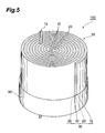
Fig. 5 is a partial-cutaway schematic perspective-view diagram illustrating an example of an electrochemical device according to an embodiment of the present invention; -
Fig. 6 is a partial-cutaway schematic perspective-view diagram illustrating another example of an electrochemical device according to an embodiment of the present invention; and -
Fig. 7 is a table listing conditions and results in examples and comparative examples. - Preferred embodiments of the present invention are explained in detail below with reference to accompanying drawings. In the drawings, identical or equivalent elements are denoted with identical reference numerals, and recurrent explanations thereof are omitted. The dimensional ratios in the drawings do not necessarily match actual dimensional ratios.
- First embodiment
An electrode forelectrochemical devices 10 according to a first embodiment will be explained with reference toFig. 1 . The electrode forelectrochemical devices 10 comprises mainly acollector 12,active material layers lead 15. - The
collector 12 is a conductive member in the form of a rectangular elongated plate. Although not particularly limited thereto, the material of the collector is preferably a metallic material, such as copper, aluminum or nickel. For instance, the electric resistivity p of copper, aluminum and nickel are 1.68×10⁻⁸Ωm, 2.65 × 10⁻⁸Ωm, 6.99×10⁻⁸ Ωm, respectively. The thickness of the collector is not particularly limited, and may range from 10 to 50 µm. Also, the length L0 in the longitudinal direction and the length W0 in the direction (width direction) perpendicular to the longitudinal direction are not particularly limited. The length L0 in the longitudinal direction may range, for instance, from 80 to 150 mm, while the length W0 in the width direction may range, for instance, from 12 to 16 mm. The aspect ratio (L0/W0) of the collector is preferably 5 to 10, more preferably about 7.0. - The
lead 15 is a conductive member that plays the role of current input terminal in thecollector 12. Thelead 15 is shaped as a rectangular plate, the longitudinal direction of thelead 15 being perpendicular to the longitudinal direction of thecollector 12. In the present embodiment, oneend face 15d of thelead 15 in the longitudinal direction extends up to oneside face 12d of thecollector 12 in the direction (width direction) perpendicular to the longitudinal direction of thecollector 12, while theother end face 15c of thelead 15, in the longitudinal direction, extends beyond theother side face 12c of thecollector 12 in a direction (width direction) that is perpendicular to the longitudinal direction of thecollector 12. The thickness of thelead 15 is not particularly limited, and may be for instance similar to that of thecollector 12. The length of thelead 15 in the longitudinal direction can be arbitrarily set in accordance with the way in which the lead is to be used, provided that theother end face 15c of thelead 15 protrudes beyond theside face 12c of thecollector 12. The length A of thelead 15, in a direction perpendicular to the longitudinal direction of thelead 15, is best sufficiently shorter than the length L0 of thecollector 12 in the longitudinal direction of the latter. For instance, thelead 15 may protrude about 10 to 25 mm beyond theside face 12c of thecollector 12, and the width A of thelead 15 may range, for instance, from 2 to 10 mm. - The
lead 15 and thecollector 12 are fixed together and electrically connected by way of, for instance, a conductive adhesive, soldering or welding.Side faces lead 15 extending in the longitudinal direction thereof are respectively parallel to end faces (one end, other end) 12a, 12b that are perpendicular to the longitudinal direction of thecollector 12. - The
active material layers collector 12. Specifically, theactive material layer 13C is provided over substantially the entire surface of thecollector 12 where thelead 15 is not provided. Meanwhile, theactive material layers collector 12 on which thelead 15 is provided, at portions other than the portion at which thelead 15 is provided. - The
active material layers active material layers - Various active materials, not particularly limited, can be used as active materials for positive electrodes of lithium-ion secondary batteries, so long as the active material is capable of storing and releasing lithium ions, desorbing and intercalating lithium ions, and allows reversible doping and dedoping of lithium ions and counter anions of lithium ions (for instance, ClO4 -). The active material may be, for instance, a lithium-containing metal oxide. Examples of lithium-containing metal oxides include, for instance, a lithium oxide comprising at least one metal selected from the group consisting of Co, Ni and Mn, such as LiMO2 (wherein M denotes Co, Ni or Mn) or LiCoxNi1-xO2, LiMn2O4 and LiCoxNiyMn1-x-yO2 (wherein x and y are greater than 0 and smaller than 1), lithium vanadium compound (LiV2O5) or olivine-like LiMPO4 (wherein M denotes Co, Ni, Mn or Fe).
- Various active materials, not particularly limited, can be used as active materials for negative electrodes of lithium-ion secondary batteries, so long as the active material is capable of storing and releasing lithium ions, desorbing and intercalating lithium ions, and allows reversible doping and dedoping of lithium ions and counter anions of lithium ions (for instance, ClO4 -). Examples include, for instance, natural graphite, artificial graphite, mesocarbon microbeads, mesocarbon fibers (MCF), coke, glass-like carbon, carbonaceous materials such as fired products of organic compounds or the like, metals that can combine with lithium, such as Al, Si or Sn, or amorphous compounds having, as a main component, an oxide such as SiO2 or SnO2.
- The electrodes for electric double-layer capacitors may be, for instance, various porous materials having electron conductivity. Suitable examples include, for instance, natural graphite, artificial graphite, mesocarbon microbeads, mesocarbon fibers (MCF), coke, glass-like carbon or carbonaceous materials such as fired products of organic compounds or the like.
- As the binder there may be used various bonding agents, not particularly limited, provided that they can fix the above active material and, preferably also the conduction enhancer, to the collector. Examples thereof include, for instance, a fluororesin such as polyvinylidene fluoride (PVDF) or polytetrafluoroethylene (PTFE), or a mixture of styrene-butadiene rubber (SBR) with a water-soluble polymer (carboxymethylcellulose, polyvinyl alcohol, sodium polyacrylate, dextrin, gluten and the like).
- Examples of the conduction enhancer include, for instance, carbon black, metal micropowders of copper, nickel, stainless steel, iron or the like, mixtures of carbon materials and metal micropowders, or conductive oxides such as ITO. The conduction enhancer is a material added with a view to increasing the electron conductivity of the
active material layers - Conventional methods may be used for forming the
active material layers active material layers collector 12, theactive material layers - In the present embodiment, the distance La between the lead 15 and an end face (one end) 12a of the
collector 12 in the longitudinal direction, and the distance Lb between the lead 15 and an end face (other end) 12b of thecollector 12 in the longitudinal direction range both from 0.95Lopt to 1.05Lopt. - Herein, Lopt (m)=1.9×10⁶ρ, with p denoting the electric resistivity (Ωm) of the
collector 12 at 25°C. - The distance La and the distance Lb can be thought of as the maximum distance covered by current in the
collector 12 when current is supplied to, and discharged from, theactive material layers collector 12. Also, Lopt is the optimal value of this maximum distance, and is determined by the electric resistivity of thecollector 12. In the present embodiment, therefore, the distance La and the distance Lb range from 95 to 105% of the optimal value Lopt. - An electrochemical device using such an electrode has enhanced characteristics, with extremely low impedance and leakage current values. Leakage current tends to increase when the distances La and Lb are smaller than 0.95Lopt, while the impedance of the electrochemical device tends to increase when the distances La and Lb exceed 1.05Lopt.
- Second embodiment
An electrode forelectrochemical devices 10 according to a second embodiment is explained next with reference toFig. 2 . The electrode forelectrochemical devices 10 according to the present embodiment differs from the electrode for electrochemical devices according to the first embodiment in the shape of thelead 15, and thus only this feature will be explained. In thelead 15 according to the second embodiment, theend face 15d does not protrude up to theside face 12d of thecollector 12, but is positioned over thesurface 12e of thecollector 12. Such an electrode forelectrochemical devices 10 elicits the same effect as that of the first embodiment. - Third embodiment
An electrode forelectrochemical devices 10 according to a third embodiment is explained next with reference toFig. 3 . The electrode forelectrochemical devices 10 according to the present embodiment differs from the electrode for electrochemical devices according to the first embodiment in the shape of thelead 15, and thus only this feature will be explained. Thelead 15 according to the third embodiment is not provided on the front face or rear face of thecollector 12 but on theside face 12d of thecollector 12. As a result, theactive material layer 13A is not split but formed as a single unit, as is the case with theactive material layer 13C. Such a lead 15 can be easily formed by cutting thecollector 12 and thelead 15 out of a single conductive plate. Such an electrode forelectrochemical devices 10 elicits the same effect as that of the first embodiment. - Fourth embodiment
An electrode forelectrochemical devices 10 according to a fourth embodiment is explained next with reference toFig. 4 . In the electrode forelectrochemical devices 10 according to the present embodiment the length of thecollector 12 in the longitudinal direction is longer than is the case in the electrode forelectrochemical devices 10 of the first embodiment. Also, there are provided n spaced-apart leads 15 in the longitudinal direction of thecollector 12, n being an integer equal to 2 or higher. The n leads are sequentially denoted as 151, 152,..., 15n, from the left ofFig. 4 . The distances La and Lb are defined in the same way as in the first embodiment and lie within the same ranges as prescribed in the first embodiment. Preferably, the number n is for instance about n=4. - Herein, L1 denotes the distance between
adjacent leads adjacent leads - As is the case with La and Lb in the first embodiment, (L1/2),(L2/2),..., (Ln-1/2) can be thought of as the maximum distances covered by the current in the
collector 12 when current is supplied to, and charging is carried out in, theelectrode 10. Also, Lopt is the optimal value of the largest distance. In the present embodiment, not only the distance L1 and the distance L2 but also (L1/2), (L2/2),..., (Ln-1/2) range all from 95% to 105% of the optimal value. - Such an electrode for
electrochemical devices 10 elicits the same effect as that of the first embodiment. Needless to say, the electrode of the second embodiment and the third embodiment may be provided as a plurality of electrodes, as in the fourth embodiment. - Electrochemical device An electrochemical device using the above-described
electrode 10 is explained next with reference toFigs. 5 and6 . The electrochemical device explained herein uses the electrode for electrochemical devices of the first embodiment, but may equally use the electrode for electrochemical devices of any of the other embodiments. - An
electrochemical device 100 illustrated inFigs. 5 and6 comprises acase 50, awound body 30 and an electrolyte solution, omitted in the figure, held in the case and impregnating thewound body 30. - The
case 50 seals thewound body 30 and prevents intrusion of air and moisture into the interior of the case. The material used in thecase 50 may be, for instance, a synthetic resin such as an epoxy resin, a laminate film in which a metal sheet of aluminum or the like is coated with a resin. Thelead 15 of thewound body 30 protrudes out of thecase 50. - The electrolyte solution (not shown) fills the inner space of the
case 50. Part of the electrolyte solution is contained in the interior of anelectrode 10, anelectrode 10 and aseparator 20. - In the case of a lithium-ion secondary battery, for instance, the electrolyte solution used may be, for instance, a nonaqueous electrolyte solution in which a lithium salt is dissolved in an organic solvent. Examples of the lithium salt include, for instance, LiPF6, LiClO4, LiBF4, LiAsF6, LiCF3SO3, LiCF3CF2SO3, LiC(CF3SO2)3, LiN(CF3SO2)2, LiN(CF3CF2SO2)2, LiN(CF3SO2)(C4F9SO2) and LiN(CF3CF2CO)2.
- In the case of an electric double-layer capacitor, for instance, there can be used an electrolyte solution obtained by dissolving a quaternary ammonium salt such as tetraethylammonium tetrafluoroborate (TEA+BF4 -) or triethylmonomethylammonium tetrafluoroborate (TEMA+BF4 -) in an organic solvent.
- These salts may be used singly or in combinations of two or more. The electrolyte solution may form a gel through addition of a polymer or the like.
- Known solvents used in electrochemical devices may be employed as the organic solvent. Preferred examples thereof include, for instance, propylene carbonate, ethylene carbonate and diethyl carbonate. These organic solvents may be used singly or in mixtures of two or more at arbitrary mixing ratios.
- The
wound body 30 is obtained by winding, in the longitudinal direction, a pair of the above-described electrodes forelectrochemical devices separator 20 is interposed between the electrodes forelectrochemical devices - Specifically, for instance, a stack resulting from stacking an
electrode 10/separator 20 /electrode 10 /separator 20 is wound into a tubular form, starting form one end of the stack, to yield thewound body 30 illustrated inFig. 5 , having a substantially tubular cross section. Also, the above-described stack may be wound several times, starting from one end, while bending the stack into a flat form, to yield thewound body 30 illustrated inFig. 6 , having a substantially oval cross section. - The position at which the
leads 15 protrude may lie in the same direction between electrodes, as illustrated inFig. 6 , or in mutually opposing directions between electrodes, as illustrated inFig. 5 . - The
separator 20, which provides electric insulation between the electrodes forelectrochemical devices - In such an electrochemical device there must be used an electrode for electrochemical devices in which La and Lb, or La, Lb, (L1/2), (L2/2),... and (Ln-1/2) are as prescribed above. Both impedance and leakage current are small in such an electrochemical device.
- The present invention is not limited to the above embodiments, and may accommodate various modifications. In the above embodiments, for instance, the collector is shaped as an elongated plate, but the collector need only be a thin a long member, i.e. need only have a longitudinal direction. The collector may thus be shaped, for instance, as an elongated wire.
- The electrochemical device is not limited to batteries such as lithium-ion secondary batteries, or to electric double-layer capacitors, and may also be realized in, for instance, electrolytic capacitors or the like.
- Examples
Electric double-layer capacitor (EDLC): Examples A1 to A3, Comparative examples A1 and A2
A coating material was prepared by mixing activated carbon particles, as the active material, and PVDF as the binder, to a ratio active material: binder = 70:30; then N-methyl pyrrolidone was added to the obtained mixture, and the whole was kneaded. The coating material was coated, using a doctor blade, onto both faces of 30 µm aluminum foil, except at the portion intended for lead placing. The resulting coating films were then dried. The aluminum foil having formed thereon the coating films was then punched into a rectangle, and then a lead having a width A of 2 mm, a length of 25 mm and a thickness of 0.1 mm was ultrasonically welded to the uncoated portion of the collector, as illustrated inFig. 1 , to yield a pair of electrodes for an electric double-layer capacitor. The length L0 of the collector in the longitudinal direction, and distances La, Lb from the ends of the collector to the lead were set as given inFig. 7 for the various examples and comparative examples. The width W0 of the collector was 10 mm. - Both faces of one of the obtained electrodes were covered with a nonwoven fabric of regenerated cellulose (
thickness 30 µm), after which the electrode was disposed opposite the other electrode, and the resulting stack was wound into a tubular shape, from one end of the stack. The wound stack was fitted into a case made of aluminum laminate film, the lead was drawn out through the opening of the laminate film, and the opening was thermocompression-bonded, flanking the lead portion. An electrolyte solution for electric double-layer capacitors was poured onto the stack through the last remaining opening of the outer bag of aluminum laminate in which the stack was placed. The remaining opening was then sealed through vacuum thermocompression bonding, followed by aging, to yield the various electric double-layer capacitors. The electrolyte solution was a solution of tetraethylammonium tetrafluoroborate (TEA+BF4 -), as the electrolyte, dissolved in propylene carbonate (PC), as an organic solvent. The electrolyte concentration in the electrolyte solution was 1.0 mol/L. - Electric double-layer capacitor: Examples A4 to A5, Comparative examples A3 and A4 Electric double-layer capacitors were obtained in the same way as in Example 1, but using herein 17 µm-thickness copper foil instead of aluminum foil, with L0, La and Lb set as in
Fig. 7 . - Lithium-ion secondary battery (LIB): Examples B1 to B3,
Comparative examples B 1 to B4
Cathode electrodes were manufactured in accordance with the procedure below. Firstly there were prepared LiCoO2 as a positive electrode active material, acetylene black as a conduction enhancer and polyvinylidene fluoride (PVdF) as a binding agent. These were mixed and dispersed in a planetary mixer to relative weights of positive electrode active material: conduction enhancer: binding agent = 90:6:4. Thereafter, the viscosity of the resulting dispersion was adjusted through addition of a suitable amount of NMP, as a solvent, to yield a slurry-like cathode coating liquid (slurry). - Aluminum foil (
thickness 20 µm) was prepared next as the collector, and the cathode coating liquid was coated to an active material carrying amount of 1.0 mg/cm2, onto both faces of the aluminum foil, except at the portion planned for lead welding, using a doctor blade. This was followed by pressing using a calender roll, to a porosity of 28% of the coated active material layers. The pressed product was punched into a rectangle, to yield the cathode electrode. The distances L0, La, Lb were set as inFig. 7 , and the width W0 was 10 mm. - Anode electrodes were manufactured next in accordance with the procedure below. Firstly there were prepared natural graphite as a negative electrode active material and polyvinylidene fluoride (PVdF) as a binding agent. These were blended, mixed and dispersed in a planetary mixer to relative weights of negative electrode active material: binding agent = 95:5). Thereafter, the viscosity of the resulting dispersion was adjusted through addition of a suitable amount of NMP, as a solvent, to yield a slurry-like anode coating liquid. Copper foil (thickness 17 µm) was prepared next, and the anode coating liquid was coated to an active material carrying amount, on the anode electrode, of 3.0mg/cm2, onto both faces of the copper foil, except at the portion planned for lead welding, using a doctor blade. This was followed by pressing using a calender roll, to a porosity of 30% of the active material layers of the anode electrode. The pressed product was punched into a rectangle, to yield the anode electrode. The distances L0, La, Lb were set as in
Fig. 7 , and the width W0 was 10 mm. - Both faces of one of the obtained electrodes were covered with a single-layer polyethylene porous film (
thickness 12 µm), as a separator, after which the electrode was disposed opposite the other electrode, and the resulting stack was wound into a tubular shape, from one end of the stack. The wound stack was fitted into a case made of aluminum laminate film, the lead was drawn out through the opening of the laminate film, and the opening was thermocompression-bonded, flanking the lead portion. An electrolyte solution for lithium-ion secondary batteries was poured onto the stack through the last remaining opening of the outer bag of aluminum laminate in which the stack was placed. The remaining opening was then sealed through vacuum thermocompression bonding, followed by aging, to yield the various lithium-ion secondary batteries. - As the electrolyte for lithium-ion secondary batteries there was used an electrolyte obtained by dissolving LiPF6, to a concentration of 1.5 mol/dm3, in a solvent resulting from mixing propylene carbonate (PC), ethylene carbonate (EC) and diethyl carbonate (DEC), to a volume ratio of 2:1:7, respectively. To 100 parts by weight of the resulting solution there were further added 3 parts by weight of 1,3-propane sultone.
- Evaluation of the electric double-layer capacitors and lithium-ion secondary batteries
The electric double-layer capacitors and lithium-ion secondary batteries of the examples and comparative examples were measured for impedance and leakage current. The values are illustrated inFig. 7 . In the electric double-layer capacitors, impedance was measured in the discharged state, while leakage current was measured after charging at 4 V for 1 hour. In the lithium-ion secondary batteries, impedance was measured in a state resulting from discharge to 3 V, while leakage current was measured after charging at 4 V for 1 hour. - In Examples A1 to A3, relating to electric double-layer capacitors using collectors made of aluminum, there was achieved an impedance of less than 100 mΩ. In Examples A4 and A5, relating to electric double-layer capacitors using collectors made of copper, there was achieved an impedance of less than 60 mΩ. In
Examples B 1 to B3, relating to lithium-ion secondary batteries, there was achieved an impedance of less than 130 mΩ. A leakage current no greater than 20 mA/h was achieved in all the examples.
Claims (4)
- An electrode for an electrochemical device, comprising: an elongated collector; a lead provided halfway along a longitudinal direction of said collector; and an active material layer provided on said collector, wherein
when La (m) is a distance from one end of said collector, in the longitudinal direction, up to said lead, Lb (m) is a distance from the other end of said collector, in the longitudinal direction, up to said lead, and p (Ωm) is a resistivity of said collector at 25°C, where Lopt (m) being 1.9×10⁶ρ,
the La (m) and Lb (m) are from 0.95 Lopt to 1.05 Lopt respectively. - An electrode for an electrochemical device, comprising: an elongated collector, n leads (n being an integer equal to 2 or greater) provided spaced apart from each other in said collector along a longitudinal direction of said collector; and an active material layer provided on said collector, wherein
when La (m) is a distance from one end of said collector, in the longitudinal direction, up to a lead closest to said one end, Lb (m) is a distance from the other end of said collector, in the longitudinal direction, up to a lead closest to said other end, L1, L2, ..., Ln-1 (m) are distances between adjacent leads, and ρ (Ωm) is a resistivity of said collector at 25°C, where Lopt (m) being 1.9×10⁶ρ,
the La and Lb are from 0.95 Lopt to 1.05 Lopt respectively, and
(L1/2), (L2/2),..., (Ln-1/2) respectively range from 0.95 Lopt to 1.05 Lopt. - An electrochemical device, comprising a pair of electrodes,
wherein both electrodes are the electrode for electrochemical devices according to claim 1. - An electrochemical device, comprising a pair of electrodes,
wherein both electrodes are the electrode for electrochemical devices according to claim 2.
Applications Claiming Priority (1)
| Application Number | Priority Date | Filing Date | Title |
|---|---|---|---|
| JP2007340307A JP4557001B2 (en) | 2007-12-28 | 2007-12-28 | Electrode for electrochemical device and electrochemical device |
Publications (2)
| Publication Number | Publication Date |
|---|---|
| EP2075862A1 true EP2075862A1 (en) | 2009-07-01 |
| EP2075862B1 EP2075862B1 (en) | 2010-06-30 |
Family
ID=40445575
Family Applications (1)
| Application Number | Title | Priority Date | Filing Date |
|---|---|---|---|
| EP08021675A Active EP2075862B1 (en) | 2007-12-28 | 2008-12-12 | Electrode for electrochemical device and electrochemical device |
Country Status (5)
| Country | Link |
|---|---|
| US (1) | US20090166192A1 (en) |
| EP (1) | EP2075862B1 (en) |
| JP (1) | JP4557001B2 (en) |
| CN (1) | CN101471437B (en) |
| DE (1) | DE602008001657D1 (en) |
Cited By (2)
| Publication number | Priority date | Publication date | Assignee | Title |
|---|---|---|---|---|
| EP2249425A4 (en) * | 2008-02-05 | 2012-12-05 | Sk Innovation Co Ltd | LITHIUM SECONDARY BATTERY AND METHOD OF MANUFACTURING THEREOF |
| US20140170471A1 (en) * | 2012-12-19 | 2014-06-19 | Gs Yuasa International Ltd. | Electrode plate, layered electrode group, battery, and cylindrical battery |
Families Citing this family (14)
| Publication number | Priority date | Publication date | Assignee | Title |
|---|---|---|---|---|
| KR101302318B1 (en) * | 2009-06-10 | 2013-08-30 | 리서치 인 모션 리미티드 | Battery for wireless mobile communication device |
| US8357460B2 (en) | 2009-07-14 | 2013-01-22 | Research In Motion Limited | Low magnetic interference battery and mobile communication device |
| KR101602543B1 (en) | 2009-07-14 | 2016-03-10 | 블랙베리 리미티드 | Low magnetic interference battery |
| JP5662441B2 (en) * | 2009-07-24 | 2015-01-28 | ブラックベリー リミテッド | Low noise battery |
| WO2011041867A1 (en) * | 2009-10-07 | 2011-04-14 | Research In Motion Limited | Low noise battery |
| KR101152515B1 (en) * | 2009-12-17 | 2012-06-01 | 삼성에스디아이 주식회사 | Electrode assembly and secondary battery using the same |
| US10446828B2 (en) * | 2011-10-21 | 2019-10-15 | Blackberry Limited | Recessed tab for higher energy density and thinner batteries |
| CN103632858B (en) * | 2012-08-28 | 2016-09-21 | 江苏国泰超威新材料有限公司 | A kind of electrolyte and the electrochemical element of this electrolyte of use |
| CN109155202B (en) | 2016-05-20 | 2021-03-09 | 阿维科斯公司 | Multi-cell supercapacitor |
| US11830672B2 (en) | 2016-11-23 | 2023-11-28 | KYOCERA AVX Components Corporation | Ultracapacitor for use in a solder reflow process |
| CN112005405B (en) * | 2018-04-06 | 2023-09-01 | 松下知识产权经营株式会社 | Manufacturing method of electrode plate, electrode body and battery |
| CN108878770B (en) * | 2018-07-02 | 2019-06-25 | 宁德时代新能源科技股份有限公司 | Battery cell and secondary battery comprising same |
| KR102826755B1 (en) | 2020-04-28 | 2025-06-27 | 닝더 엠프렉스 테크놀로지 리미티드 | Electrochemical device and electronic device comprising the electrochemical device |
| DE102024119240A1 (en) * | 2024-07-05 | 2026-01-08 | Lilectra Corporation | Filter cartridge for extracting lithium from brine, filter cartridge assembly and device |
Citations (12)
| Publication number | Priority date | Publication date | Assignee | Title |
|---|---|---|---|---|
| JPH07192717A (en) | 1993-12-24 | 1995-07-28 | Sony Corp | Non-aqueous electrolyte secondary battery |
| JPH11283883A (en) | 1998-03-27 | 1999-10-15 | Nichicon Corp | Electrolytic capacitor |
| JPH11283882A (en) | 1998-03-27 | 1999-10-15 | Nichicon Corp | Electrolytic capacitor |
| JPH11317218A (en) | 1998-04-30 | 1999-11-16 | Toyota Central Res & Dev Lab Inc | Sheet electrode |
| EP0973214A1 (en) * | 1998-07-14 | 2000-01-19 | Ngk Insulators, Ltd. | Lithium secondary battery |
| JP2000106167A (en) | 1998-09-30 | 2000-04-11 | Mitsubishi Electric Corp | Battery |
| JP2000182656A (en) | 1998-12-15 | 2000-06-30 | Ngk Insulators Ltd | Lithium secondary battery |
| EP1020943A1 (en) * | 1997-09-30 | 2000-07-19 | Sanyo Electric Co., Ltd. | Lithium secondary battery and method for manufacturing the same |
| JP2001110453A (en) | 1999-10-04 | 2001-04-20 | Sony Corp | Non-aqueous electrolyte secondary battery |
| US20020187395A1 (en) * | 1997-11-10 | 2002-12-12 | Ngk Insulators, Ltd. | Lithium secondary battery |
| JP2006260892A (en) | 2005-03-16 | 2006-09-28 | Dainippon Printing Co Ltd | Non-aqueous electrolyte secondary battery electrode plate, method for producing the same, and non-aqueous electrolyte secondary battery |
| JP2006286404A (en) | 2005-03-31 | 2006-10-19 | Dainippon Printing Co Ltd | Combination of positive electrode plate and negative electrode plate of electrode plate for non-aqueous electrolyte secondary battery, method for manufacturing the positive electrode plate and negative electrode plate, and non-aqueous electrolyte secondary battery |
Family Cites Families (13)
| Publication number | Priority date | Publication date | Assignee | Title |
|---|---|---|---|---|
| JPS4112666Y1 (en) * | 1964-10-13 | 1966-06-15 | ||
| JPS52164224U (en) * | 1976-06-07 | 1977-12-13 | ||
| JPS63124361A (en) * | 1986-11-12 | 1988-05-27 | Matsushita Electric Ind Co Ltd | Battery plate |
| JPH0415156U (en) * | 1990-05-29 | 1992-02-06 | ||
| US5434017A (en) * | 1993-11-19 | 1995-07-18 | Medtronic, Inc. | Isolated connection for an electrochemical cell |
| JP3140977B2 (en) * | 1997-03-19 | 2001-03-05 | 三洋電機株式会社 | Lithium secondary battery |
| JP2000243376A (en) * | 1999-02-24 | 2000-09-08 | Matsushita Electric Ind Co Ltd | Lithium secondary battery |
| JP4389398B2 (en) * | 2001-03-13 | 2009-12-24 | 新神戸電機株式会社 | Non-aqueous electrolyte secondary battery |
| JP3729112B2 (en) * | 2001-09-20 | 2005-12-21 | ソニー株式会社 | Solid electrolyte battery |
| JP2004234994A (en) * | 2003-01-30 | 2004-08-19 | Hitachi Ltd | Lithium secondary battery, its assembled battery and its electrode |
| SE527979C2 (en) * | 2004-05-07 | 2006-07-25 | Effpower Ab | End electrode for bipolar battery, biolayer battery and method for producing end electrode |
| US8084158B2 (en) * | 2005-09-02 | 2011-12-27 | A123 Systems, Inc. | Battery tab location design and method of construction |
| TWI270994B (en) * | 2005-12-29 | 2007-01-11 | Ind Tech Res Inst | High rate capability design of lithium ion secondary battery |
-
2007
- 2007-12-28 JP JP2007340307A patent/JP4557001B2/en active Active
-
2008
- 2008-12-12 EP EP08021675A patent/EP2075862B1/en active Active
- 2008-12-12 DE DE602008001657T patent/DE602008001657D1/en active Active
- 2008-12-22 US US12/341,135 patent/US20090166192A1/en not_active Abandoned
- 2008-12-29 CN CN2008101891224A patent/CN101471437B/en active Active
Patent Citations (12)
| Publication number | Priority date | Publication date | Assignee | Title |
|---|---|---|---|---|
| JPH07192717A (en) | 1993-12-24 | 1995-07-28 | Sony Corp | Non-aqueous electrolyte secondary battery |
| EP1020943A1 (en) * | 1997-09-30 | 2000-07-19 | Sanyo Electric Co., Ltd. | Lithium secondary battery and method for manufacturing the same |
| US20020187395A1 (en) * | 1997-11-10 | 2002-12-12 | Ngk Insulators, Ltd. | Lithium secondary battery |
| JPH11283883A (en) | 1998-03-27 | 1999-10-15 | Nichicon Corp | Electrolytic capacitor |
| JPH11283882A (en) | 1998-03-27 | 1999-10-15 | Nichicon Corp | Electrolytic capacitor |
| JPH11317218A (en) | 1998-04-30 | 1999-11-16 | Toyota Central Res & Dev Lab Inc | Sheet electrode |
| EP0973214A1 (en) * | 1998-07-14 | 2000-01-19 | Ngk Insulators, Ltd. | Lithium secondary battery |
| JP2000106167A (en) | 1998-09-30 | 2000-04-11 | Mitsubishi Electric Corp | Battery |
| JP2000182656A (en) | 1998-12-15 | 2000-06-30 | Ngk Insulators Ltd | Lithium secondary battery |
| JP2001110453A (en) | 1999-10-04 | 2001-04-20 | Sony Corp | Non-aqueous electrolyte secondary battery |
| JP2006260892A (en) | 2005-03-16 | 2006-09-28 | Dainippon Printing Co Ltd | Non-aqueous electrolyte secondary battery electrode plate, method for producing the same, and non-aqueous electrolyte secondary battery |
| JP2006286404A (en) | 2005-03-31 | 2006-10-19 | Dainippon Printing Co Ltd | Combination of positive electrode plate and negative electrode plate of electrode plate for non-aqueous electrolyte secondary battery, method for manufacturing the positive electrode plate and negative electrode plate, and non-aqueous electrolyte secondary battery |
Cited By (2)
| Publication number | Priority date | Publication date | Assignee | Title |
|---|---|---|---|---|
| EP2249425A4 (en) * | 2008-02-05 | 2012-12-05 | Sk Innovation Co Ltd | LITHIUM SECONDARY BATTERY AND METHOD OF MANUFACTURING THEREOF |
| US20140170471A1 (en) * | 2012-12-19 | 2014-06-19 | Gs Yuasa International Ltd. | Electrode plate, layered electrode group, battery, and cylindrical battery |
Also Published As
| Publication number | Publication date |
|---|---|
| JP2009163929A (en) | 2009-07-23 |
| JP4557001B2 (en) | 2010-10-06 |
| CN101471437A (en) | 2009-07-01 |
| US20090166192A1 (en) | 2009-07-02 |
| DE602008001657D1 (en) | 2010-08-12 |
| CN101471437B (en) | 2011-05-04 |
| EP2075862B1 (en) | 2010-06-30 |
Similar Documents
| Publication | Publication Date | Title |
|---|---|---|
| EP2075862B1 (en) | Electrode for electrochemical device and electrochemical device | |
| JP5157244B2 (en) | Electrochemical device and manufacturing method thereof | |
| US8114543B2 (en) | Lithium ion secondary battery | |
| US9412995B2 (en) | Electrode and electrochemical device | |
| JP4041044B2 (en) | Method for manufacturing electrochemical device | |
| JP5195341B2 (en) | Lithium ion secondary battery separator and lithium ion secondary battery | |
| JP4283598B2 (en) | Non-aqueous electrolyte solution and lithium ion secondary battery | |
| JP2010121029A (en) | Fiber-containing polymer film and method of manufacturing the same, and electrochemical device and method of manufacturing the same | |
| JP2008251249A (en) | Anode and lithium ion secondary battery | |
| JP4109184B2 (en) | Lithium ion secondary battery | |
| US12322795B2 (en) | Lithium ion secondary battery | |
| US12531237B2 (en) | Lithium ion secondary battery | |
| JP5109441B2 (en) | Lithium ion secondary battery manufacturing method and lithium ion secondary battery | |
| US12573631B2 (en) | Lithium ion secondary battery | |
| WO2015046394A1 (en) | Negative-electrode active material, negative electrode using same, and lithium-ion secondary battery | |
| JP2005011762A (en) | Lithium ion secondary battery | |
| JP2015128052A (en) | Electricity storage element | |
| JP4560851B2 (en) | Method for producing solid electrolyte battery | |
| JP4109168B2 (en) | Lithium ion secondary battery | |
| JP7749832B2 (en) | Negative electrode active material layer, negative electrode and lithium ion secondary battery | |
| WO2024181069A1 (en) | Negative electrode for lithium-ion secondary batteries, and lithium-ion secondary battery | |
| WO2023106099A1 (en) | Battery | |
| JP3887612B2 (en) | Non-aqueous electrolyte solution and lithium ion secondary battery | |
| WO2023238325A1 (en) | Negative electrode active material layer, negative electrode, and lithium-ion rechargeable battery | |
| JP2012074232A (en) | Electrode for battery, and battery |
Legal Events
| Date | Code | Title | Description |
|---|---|---|---|
| PUAI | Public reference made under article 153(3) epc to a published international application that has entered the european phase |
Free format text: ORIGINAL CODE: 0009012 |
|
| 17P | Request for examination filed |
Effective date: 20081212 |
|
| AK | Designated contracting states |
Kind code of ref document: A1 Designated state(s): AT BE BG CH CY CZ DE DK EE ES FI FR GB GR HR HU IE IS IT LI LT LU LV MC MT NL NO PL PT RO SE SI SK TR |
|
| AX | Request for extension of the european patent |
Extension state: AL BA MK RS |
|
| GRAP | Despatch of communication of intention to grant a patent |
Free format text: ORIGINAL CODE: EPIDOSNIGR1 |
|
| GRAC | Information related to communication of intention to grant a patent modified |
Free format text: ORIGINAL CODE: EPIDOSCIGR1 |
|
| AKX | Designation fees paid |
Designated state(s): DE FR GB |
|
| GRAS | Grant fee paid |
Free format text: ORIGINAL CODE: EPIDOSNIGR3 |
|
| GRAA | (expected) grant |
Free format text: ORIGINAL CODE: 0009210 |
|
| AK | Designated contracting states |
Kind code of ref document: B1 Designated state(s): DE FR GB |
|
| REG | Reference to a national code |
Ref country code: GB Ref legal event code: FG4D |
|
| REF | Corresponds to: |
Ref document number: 602008001657 Country of ref document: DE Date of ref document: 20100812 Kind code of ref document: P |
|
| REG | Reference to a national code |
Ref country code: DE Ref legal event code: R096 Ref document number: 602008001657 Country of ref document: DE Effective date: 20100812 |
|
| PLBE | No opposition filed within time limit |
Free format text: ORIGINAL CODE: 0009261 |
|
| STAA | Information on the status of an ep patent application or granted ep patent |
Free format text: STATUS: NO OPPOSITION FILED WITHIN TIME LIMIT |
|
| 26N | No opposition filed |
Effective date: 20110331 |
|
| REG | Reference to a national code |
Ref country code: DE Ref legal event code: R097 Ref document number: 602008001657 Country of ref document: DE Effective date: 20110330 Ref country code: DE Ref legal event code: R097 Ref document number: 602008001657 Country of ref document: DE Effective date: 20110331 |
|
| GBPC | Gb: european patent ceased through non-payment of renewal fee |
Effective date: 20121212 |
|
| PG25 | Lapsed in a contracting state [announced via postgrant information from national office to epo] |
Ref country code: GB Free format text: LAPSE BECAUSE OF NON-PAYMENT OF DUE FEES Effective date: 20121212 |
|
| REG | Reference to a national code |
Ref country code: FR Ref legal event code: PLFP Year of fee payment: 8 |
|
| REG | Reference to a national code |
Ref country code: FR Ref legal event code: PLFP Year of fee payment: 9 |
|
| REG | Reference to a national code |
Ref country code: FR Ref legal event code: PLFP Year of fee payment: 10 |
|
| REG | Reference to a national code |
Ref country code: DE Ref legal event code: R079 Ref document number: 602008001657 Country of ref document: DE Free format text: PREVIOUS MAIN CLASS: H01M0002260000 Ipc: H01M0050531000 |
|
| P01 | Opt-out of the competence of the unified patent court (upc) registered |
Effective date: 20230512 |
|
| PGFP | Annual fee paid to national office [announced via postgrant information from national office to epo] |
Ref country code: DE Payment date: 20251028 Year of fee payment: 18 |
|
| PGFP | Annual fee paid to national office [announced via postgrant information from national office to epo] |
Ref country code: FR Payment date: 20251110 Year of fee payment: 18 |