EP2075585A1 - Microchip reaction detection system, and method of reaction of microchip in flow path - Google Patents
Microchip reaction detection system, and method of reaction of microchip in flow path Download PDFInfo
- Publication number
- EP2075585A1 EP2075585A1 EP07807798A EP07807798A EP2075585A1 EP 2075585 A1 EP2075585 A1 EP 2075585A1 EP 07807798 A EP07807798 A EP 07807798A EP 07807798 A EP07807798 A EP 07807798A EP 2075585 A1 EP2075585 A1 EP 2075585A1
- Authority
- EP
- European Patent Office
- Prior art keywords
- reaction
- microchip
- detection unit
- solution
- flow path
- Prior art date
- Legal status (The legal status is an assumption and is not a legal conclusion. Google has not performed a legal analysis and makes no representation as to the accuracy of the status listed.)
- Withdrawn
Links
- 238000001514 detection method Methods 0.000 title claims abstract description 138
- 238000006243 chemical reaction Methods 0.000 title claims abstract description 97
- 238000000034 method Methods 0.000 title claims description 20
- 239000007788 liquid Substances 0.000 claims abstract description 102
- 239000000243 solution Substances 0.000 claims abstract description 86
- 238000002347 injection Methods 0.000 claims abstract description 49
- 239000007924 injection Substances 0.000 claims abstract description 49
- 239000000126 substance Substances 0.000 claims abstract description 39
- 229960002685 biotin Drugs 0.000 claims description 6
- 239000011616 biotin Substances 0.000 claims description 6
- 239000000427 antigen Substances 0.000 claims description 3
- 102000036639 antigens Human genes 0.000 claims description 3
- 108091007433 antigens Proteins 0.000 claims description 3
- 238000009396 hybridization Methods 0.000 claims description 3
- 239000003153 chemical reaction reagent Substances 0.000 description 31
- 239000000758 substrate Substances 0.000 description 30
- 238000012856 packing Methods 0.000 description 22
- 238000003860 storage Methods 0.000 description 19
- 238000012360 testing method Methods 0.000 description 19
- 238000010586 diagram Methods 0.000 description 14
- 108090000623 proteins and genes Proteins 0.000 description 14
- 230000003321 amplification Effects 0.000 description 11
- 238000004458 analytical method Methods 0.000 description 11
- 239000000463 material Substances 0.000 description 11
- 238000003199 nucleic acid amplification method Methods 0.000 description 11
- 238000003780 insertion Methods 0.000 description 9
- 230000037431 insertion Effects 0.000 description 9
- 238000004140 cleaning Methods 0.000 description 7
- 239000011521 glass Substances 0.000 description 7
- YBJHBAHKTGYVGT-ZKWXMUAHSA-N (+)-Biotin Chemical compound N1C(=O)N[C@@H]2[C@H](CCCCC(=O)O)SC[C@@H]21 YBJHBAHKTGYVGT-ZKWXMUAHSA-N 0.000 description 6
- 238000012545 processing Methods 0.000 description 6
- 230000035484 reaction time Effects 0.000 description 6
- 229920003023 plastic Polymers 0.000 description 5
- 238000007514 turning Methods 0.000 description 5
- 239000002699 waste material Substances 0.000 description 5
- 238000010276 construction Methods 0.000 description 4
- 230000003287 optical effect Effects 0.000 description 4
- 239000004033 plastic Substances 0.000 description 4
- 102000004169 proteins and genes Human genes 0.000 description 4
- 235000020958 biotin Nutrition 0.000 description 3
- 238000005516 engineering process Methods 0.000 description 3
- 239000012530 fluid Substances 0.000 description 3
- PCHJSUWPFVWCPO-UHFFFAOYSA-N gold Chemical class [Au] PCHJSUWPFVWCPO-UHFFFAOYSA-N 0.000 description 3
- 239000000523 sample Substances 0.000 description 3
- XLYOFNOQVPJJNP-UHFFFAOYSA-N water Substances O XLYOFNOQVPJJNP-UHFFFAOYSA-N 0.000 description 3
- 230000004544 DNA amplification Effects 0.000 description 2
- VYPSYNLAJGMNEJ-UHFFFAOYSA-N Silicium dioxide Chemical compound O=[Si]=O VYPSYNLAJGMNEJ-UHFFFAOYSA-N 0.000 description 2
- 238000010521 absorption reaction Methods 0.000 description 2
- 230000008859 change Effects 0.000 description 2
- 239000000470 constituent Substances 0.000 description 2
- 238000005859 coupling reaction Methods 0.000 description 2
- MHMNJMPURVTYEJ-UHFFFAOYSA-N fluorescein-5-isothiocyanate Chemical compound O1C(=O)C2=CC(N=C=S)=CC=C2C21C1=CC=C(O)C=C1OC1=CC(O)=CC=C21 MHMNJMPURVTYEJ-UHFFFAOYSA-N 0.000 description 2
- 230000006870 function Effects 0.000 description 2
- 238000010438 heat treatment Methods 0.000 description 2
- 238000003754 machining Methods 0.000 description 2
- 238000005259 measurement Methods 0.000 description 2
- 230000007246 mechanism Effects 0.000 description 2
- 239000004417 polycarbonate Substances 0.000 description 2
- 230000002265 prevention Effects 0.000 description 2
- 230000002940 repellent Effects 0.000 description 2
- 239000005871 repellent Substances 0.000 description 2
- 229910052710 silicon Inorganic materials 0.000 description 2
- 239000010703 silicon Substances 0.000 description 2
- 239000012780 transparent material Substances 0.000 description 2
- 238000000018 DNA microarray Methods 0.000 description 1
- 239000004743 Polypropylene Substances 0.000 description 1
- 239000004793 Polystyrene Substances 0.000 description 1
- 108010090804 Streptavidin Proteins 0.000 description 1
- 238000004026 adhesive bonding Methods 0.000 description 1
- 239000003513 alkali Substances 0.000 description 1
- 230000005540 biological transmission Effects 0.000 description 1
- 238000007664 blowing Methods 0.000 description 1
- 238000011109 contamination Methods 0.000 description 1
- 238000003745 diagnosis Methods 0.000 description 1
- 230000000694 effects Effects 0.000 description 1
- 230000007613 environmental effect Effects 0.000 description 1
- 230000004927 fusion Effects 0.000 description 1
- 238000004519 manufacturing process Methods 0.000 description 1
- 238000005459 micromachining Methods 0.000 description 1
- 230000000149 penetrating effect Effects 0.000 description 1
- 229920000515 polycarbonate Polymers 0.000 description 1
- -1 polypropylene Polymers 0.000 description 1
- 229920001155 polypropylene Polymers 0.000 description 1
- 229920002223 polystyrene Polymers 0.000 description 1
- 238000007639 printing Methods 0.000 description 1
- 230000008569 process Effects 0.000 description 1
- 230000035939 shock Effects 0.000 description 1
- 238000003786 synthesis reaction Methods 0.000 description 1
- 230000008685 targeting Effects 0.000 description 1
- 238000012956 testing procedure Methods 0.000 description 1
- 238000011144 upstream manufacturing Methods 0.000 description 1
Images


Classifications
-
- G—PHYSICS
- G01—MEASURING; TESTING
- G01N—INVESTIGATING OR ANALYSING MATERIALS BY DETERMINING THEIR CHEMICAL OR PHYSICAL PROPERTIES
- G01N35/00—Automatic analysis not limited to methods or materials provided for in any single one of groups G01N1/00 - G01N33/00; Handling materials therefor
- G01N35/08—Automatic analysis not limited to methods or materials provided for in any single one of groups G01N1/00 - G01N33/00; Handling materials therefor using a stream of discrete samples flowing along a tube system, e.g. flow injection analysis
-
- B—PERFORMING OPERATIONS; TRANSPORTING
- B01—PHYSICAL OR CHEMICAL PROCESSES OR APPARATUS IN GENERAL
- B01L—CHEMICAL OR PHYSICAL LABORATORY APPARATUS FOR GENERAL USE
- B01L3/00—Containers or dishes for laboratory use, e.g. laboratory glassware; Droppers
- B01L3/50—Containers for the purpose of retaining a material to be analysed, e.g. test tubes
- B01L3/502—Containers for the purpose of retaining a material to be analysed, e.g. test tubes with fluid transport, e.g. in multi-compartment structures
- B01L3/5027—Containers for the purpose of retaining a material to be analysed, e.g. test tubes with fluid transport, e.g. in multi-compartment structures by integrated microfluidic structures, i.e. dimensions of channels and chambers are such that surface tension forces are important, e.g. lab-on-a-chip
- B01L3/502769—Containers for the purpose of retaining a material to be analysed, e.g. test tubes with fluid transport, e.g. in multi-compartment structures by integrated microfluidic structures, i.e. dimensions of channels and chambers are such that surface tension forces are important, e.g. lab-on-a-chip characterised by multiphase flow arrangements
- B01L3/502784—Containers for the purpose of retaining a material to be analysed, e.g. test tubes with fluid transport, e.g. in multi-compartment structures by integrated microfluidic structures, i.e. dimensions of channels and chambers are such that surface tension forces are important, e.g. lab-on-a-chip characterised by multiphase flow arrangements specially adapted for droplet or plug flow, e.g. digital microfluidics
-
- B—PERFORMING OPERATIONS; TRANSPORTING
- B01—PHYSICAL OR CHEMICAL PROCESSES OR APPARATUS IN GENERAL
- B01J—CHEMICAL OR PHYSICAL PROCESSES, e.g. CATALYSIS OR COLLOID CHEMISTRY; THEIR RELEVANT APPARATUS
- B01J2219/00—Chemical, physical or physico-chemical processes in general; Their relevant apparatus
- B01J2219/00274—Sequential or parallel reactions; Apparatus and devices for combinatorial chemistry or for making arrays; Chemical library technology
- B01J2219/00277—Apparatus
- B01J2219/00279—Features relating to reactor vessels
- B01J2219/00281—Individual reactor vessels
- B01J2219/00286—Reactor vessels with top and bottom openings
-
- B—PERFORMING OPERATIONS; TRANSPORTING
- B01—PHYSICAL OR CHEMICAL PROCESSES OR APPARATUS IN GENERAL
- B01J—CHEMICAL OR PHYSICAL PROCESSES, e.g. CATALYSIS OR COLLOID CHEMISTRY; THEIR RELEVANT APPARATUS
- B01J2219/00—Chemical, physical or physico-chemical processes in general; Their relevant apparatus
- B01J2219/00274—Sequential or parallel reactions; Apparatus and devices for combinatorial chemistry or for making arrays; Chemical library technology
- B01J2219/00277—Apparatus
- B01J2219/00351—Means for dispensing and evacuation of reagents
- B01J2219/00353—Pumps
-
- B—PERFORMING OPERATIONS; TRANSPORTING
- B01—PHYSICAL OR CHEMICAL PROCESSES OR APPARATUS IN GENERAL
- B01J—CHEMICAL OR PHYSICAL PROCESSES, e.g. CATALYSIS OR COLLOID CHEMISTRY; THEIR RELEVANT APPARATUS
- B01J2219/00—Chemical, physical or physico-chemical processes in general; Their relevant apparatus
- B01J2219/00274—Sequential or parallel reactions; Apparatus and devices for combinatorial chemistry or for making arrays; Chemical library technology
- B01J2219/00277—Apparatus
- B01J2219/00495—Means for heating or cooling the reaction vessels
-
- B—PERFORMING OPERATIONS; TRANSPORTING
- B01—PHYSICAL OR CHEMICAL PROCESSES OR APPARATUS IN GENERAL
- B01J—CHEMICAL OR PHYSICAL PROCESSES, e.g. CATALYSIS OR COLLOID CHEMISTRY; THEIR RELEVANT APPARATUS
- B01J2219/00—Chemical, physical or physico-chemical processes in general; Their relevant apparatus
- B01J2219/00274—Sequential or parallel reactions; Apparatus and devices for combinatorial chemistry or for making arrays; Chemical library technology
- B01J2219/00583—Features relative to the processes being carried out
- B01J2219/00585—Parallel processes
-
- B—PERFORMING OPERATIONS; TRANSPORTING
- B01—PHYSICAL OR CHEMICAL PROCESSES OR APPARATUS IN GENERAL
- B01J—CHEMICAL OR PHYSICAL PROCESSES, e.g. CATALYSIS OR COLLOID CHEMISTRY; THEIR RELEVANT APPARATUS
- B01J2219/00—Chemical, physical or physico-chemical processes in general; Their relevant apparatus
- B01J2219/00274—Sequential or parallel reactions; Apparatus and devices for combinatorial chemistry or for making arrays; Chemical library technology
- B01J2219/00583—Features relative to the processes being carried out
- B01J2219/0059—Sequential processes
-
- B—PERFORMING OPERATIONS; TRANSPORTING
- B01—PHYSICAL OR CHEMICAL PROCESSES OR APPARATUS IN GENERAL
- B01J—CHEMICAL OR PHYSICAL PROCESSES, e.g. CATALYSIS OR COLLOID CHEMISTRY; THEIR RELEVANT APPARATUS
- B01J2219/00—Chemical, physical or physico-chemical processes in general; Their relevant apparatus
- B01J2219/00274—Sequential or parallel reactions; Apparatus and devices for combinatorial chemistry or for making arrays; Chemical library technology
- B01J2219/0068—Means for controlling the apparatus of the process
- B01J2219/00702—Processes involving means for analysing and characterising the products
-
- B—PERFORMING OPERATIONS; TRANSPORTING
- B01—PHYSICAL OR CHEMICAL PROCESSES OR APPARATUS IN GENERAL
- B01J—CHEMICAL OR PHYSICAL PROCESSES, e.g. CATALYSIS OR COLLOID CHEMISTRY; THEIR RELEVANT APPARATUS
- B01J2219/00—Chemical, physical or physico-chemical processes in general; Their relevant apparatus
- B01J2219/00274—Sequential or parallel reactions; Apparatus and devices for combinatorial chemistry or for making arrays; Chemical library technology
- B01J2219/00718—Type of compounds synthesised
- B01J2219/0072—Organic compounds
- B01J2219/00722—Nucleotides
-
- B—PERFORMING OPERATIONS; TRANSPORTING
- B01—PHYSICAL OR CHEMICAL PROCESSES OR APPARATUS IN GENERAL
- B01J—CHEMICAL OR PHYSICAL PROCESSES, e.g. CATALYSIS OR COLLOID CHEMISTRY; THEIR RELEVANT APPARATUS
- B01J2219/00—Chemical, physical or physico-chemical processes in general; Their relevant apparatus
- B01J2219/00274—Sequential or parallel reactions; Apparatus and devices for combinatorial chemistry or for making arrays; Chemical library technology
- B01J2219/00718—Type of compounds synthesised
- B01J2219/0072—Organic compounds
- B01J2219/00725—Peptides
-
- B—PERFORMING OPERATIONS; TRANSPORTING
- B01—PHYSICAL OR CHEMICAL PROCESSES OR APPARATUS IN GENERAL
- B01J—CHEMICAL OR PHYSICAL PROCESSES, e.g. CATALYSIS OR COLLOID CHEMISTRY; THEIR RELEVANT APPARATUS
- B01J2219/00—Chemical, physical or physico-chemical processes in general; Their relevant apparatus
- B01J2219/00274—Sequential or parallel reactions; Apparatus and devices for combinatorial chemistry or for making arrays; Chemical library technology
- B01J2219/00718—Type of compounds synthesised
- B01J2219/0072—Organic compounds
- B01J2219/0074—Biological products
-
- B—PERFORMING OPERATIONS; TRANSPORTING
- B01—PHYSICAL OR CHEMICAL PROCESSES OR APPARATUS IN GENERAL
- B01L—CHEMICAL OR PHYSICAL LABORATORY APPARATUS FOR GENERAL USE
- B01L2200/00—Solutions for specific problems relating to chemical or physical laboratory apparatus
- B01L2200/06—Fluid handling related problems
- B01L2200/0673—Handling of plugs of fluid surrounded by immiscible fluid
-
- B—PERFORMING OPERATIONS; TRANSPORTING
- B01—PHYSICAL OR CHEMICAL PROCESSES OR APPARATUS IN GENERAL
- B01L—CHEMICAL OR PHYSICAL LABORATORY APPARATUS FOR GENERAL USE
- B01L2300/00—Additional constructional details
- B01L2300/08—Geometry, shape and general structure
- B01L2300/0809—Geometry, shape and general structure rectangular shaped
- B01L2300/0816—Cards, e.g. flat sample carriers usually with flow in two horizontal directions
-
- B—PERFORMING OPERATIONS; TRANSPORTING
- B01—PHYSICAL OR CHEMICAL PROCESSES OR APPARATUS IN GENERAL
- B01L—CHEMICAL OR PHYSICAL LABORATORY APPARATUS FOR GENERAL USE
- B01L2300/00—Additional constructional details
- B01L2300/08—Geometry, shape and general structure
- B01L2300/0861—Configuration of multiple channels and/or chambers in a single devices
- B01L2300/0867—Multiple inlets and one sample wells, e.g. mixing, dilution
-
- B—PERFORMING OPERATIONS; TRANSPORTING
- B01—PHYSICAL OR CHEMICAL PROCESSES OR APPARATUS IN GENERAL
- B01L—CHEMICAL OR PHYSICAL LABORATORY APPARATUS FOR GENERAL USE
- B01L2300/00—Additional constructional details
- B01L2300/18—Means for temperature control
- B01L2300/1805—Conductive heating, heat from thermostatted solids is conducted to receptacles, e.g. heating plates, blocks
- B01L2300/1822—Conductive heating, heat from thermostatted solids is conducted to receptacles, e.g. heating plates, blocks using Peltier elements
-
- B—PERFORMING OPERATIONS; TRANSPORTING
- B01—PHYSICAL OR CHEMICAL PROCESSES OR APPARATUS IN GENERAL
- B01L—CHEMICAL OR PHYSICAL LABORATORY APPARATUS FOR GENERAL USE
- B01L2400/00—Moving or stopping fluids
- B01L2400/04—Moving fluids with specific forces or mechanical means
- B01L2400/0475—Moving fluids with specific forces or mechanical means specific mechanical means and fluid pressure
- B01L2400/0487—Moving fluids with specific forces or mechanical means specific mechanical means and fluid pressure fluid pressure, pneumatics
-
- B—PERFORMING OPERATIONS; TRANSPORTING
- B01—PHYSICAL OR CHEMICAL PROCESSES OR APPARATUS IN GENERAL
- B01L—CHEMICAL OR PHYSICAL LABORATORY APPARATUS FOR GENERAL USE
- B01L7/00—Heating or cooling apparatus; Heat insulating devices
- B01L7/52—Heating or cooling apparatus; Heat insulating devices with provision for submitting samples to a predetermined sequence of different temperatures, e.g. for treating nucleic acid samples
-
- G—PHYSICS
- G01—MEASURING; TESTING
- G01N—INVESTIGATING OR ANALYSING MATERIALS BY DETERMINING THEIR CHEMICAL OR PHYSICAL PROPERTIES
- G01N35/00—Automatic analysis not limited to methods or materials provided for in any single one of groups G01N1/00 - G01N33/00; Handling materials therefor
- G01N35/00029—Automatic analysis not limited to methods or materials provided for in any single one of groups G01N1/00 - G01N33/00; Handling materials therefor provided with flat sample substrates, e.g. slides
- G01N2035/00099—Characterised by type of test elements
- G01N2035/00158—Elements containing microarrays, i.e. "biochip"
-
- G—PHYSICS
- G01—MEASURING; TESTING
- G01N—INVESTIGATING OR ANALYSING MATERIALS BY DETERMINING THEIR CHEMICAL OR PHYSICAL PROPERTIES
- G01N35/00—Automatic analysis not limited to methods or materials provided for in any single one of groups G01N1/00 - G01N33/00; Handling materials therefor
- G01N2035/00346—Heating or cooling arrangements
- G01N2035/00356—Holding samples at elevated temperature (incubation)
- G01N2035/00366—Several different temperatures used
-
- G—PHYSICS
- G01—MEASURING; TESTING
- G01N—INVESTIGATING OR ANALYSING MATERIALS BY DETERMINING THEIR CHEMICAL OR PHYSICAL PROPERTIES
- G01N35/00—Automatic analysis not limited to methods or materials provided for in any single one of groups G01N1/00 - G01N33/00; Handling materials therefor
- G01N35/00584—Control arrangements for automatic analysers
- G01N2035/0097—Control arrangements for automatic analysers monitoring reactions as a function of time
Definitions
- the present invention relates to microchip reaction detection systems, and to methods of detecting the reactions of microchips in the flow path.
- Microchips are being used for the amplification and detection of a specific gene in a sample.
- a reacting substance is supported in advance on the flow path wall surface of the detection unit inside the chip, and by making a plurality of fluids such as reagents flow through this flow path in succession, reactions are carried out by making the supported reacting substance come into contact with these fluids in succession.
- Patent Document 1 Japanese Unexamined Patent Application Publication No. 2004-28589 .
- Patent Document 2 Japanese Unexamined Patent Application Publication No. 2001-322099 .
- Patent Document 3 Japanese Unexamined Patent Application Publication No. 2004-108285 .
- Patent Document 4 Japanese Unexamined Patent Application Publication No. 2004-270537 .
- the present invention was made in view of the above problem, and the purpose of the present invention is to provide a microchip reaction detection system in which it is possible to speed up the progress of a reaction by making a solution flow efficiently with respect to the reacting substance supported on the wall of the flow path of the detection unit, and to provide a reaction method inside the flow path of the microchip.
- the purpose of the present invention can be achieved by the following configuration.
- Figure 1 is an outline diagram of a reaction detection apparatus 80 according to a preferred embodiment of the present invention.
- the reaction detection apparatus 80 is an apparatus that automatically detects the reaction between the specimen under examination that has been injected in advance into the microchip 1 and a reagent, and displays the results in the display unit 84.
- An insertion inlet 83 is present in the chassis 82 of the reaction detection apparatus 80, and the microchip 1 is set inside the chassis 82 by inserting it in the insertion inlet 83. Further, the insertion inlet 83 has a height that is sufficiently more than the thickness of the microchip 1 so that the microchip 1 does not come into contact with the insertion inlet 83 when it is inserted.
- the symbol 85 is a memory card slot
- 86 is a printer output outlet
- 87 is an operation panel
- 88 are the input/output pins.
- the person in charge of testing inserts the microchip 1 in the direction of the arrow shown in Figure 1 , and starts the test by operating the operation panel 87.
- the testing of the reaction inside the microchip 1 is carried out automatically, and when the testing ends, the results are displayed on the display unit 84 configured using an LCD panel, etc.
- the test results can either be printed out via the print outlet 86, or can be stored in a memory card inserted in the memory card slot 85. Further, the data can be stored in a PC, etc., via the external input/output pins 88 using, for example, a LAN cable.
- the person in charge of testing after the testing has ended, takes out the microchip 1 from the insertion inlet 83.
- Figures 2(a) and 2(b) are external view diagrams of a microchip 1.
- the arrow mark in Figure 2(a) is the direction of inserting the microchip 1 in the reaction detection apparatus 80 to be described later, and Figure 2(a) is showing the surface that becomes the bottom surface of the microchip 1 at the time it is inserted.
- Figure 2(b) is a side view diagram of the microchip 1.
- the window 111a of the detection unit and the flow path 111b of the detection unit of Figure 2(a) have been provided for optically detecting the reaction between the specimen under examination and the reagent, and are made of a transparent material such as glass, or plastic.
- 110a, 110b, 110c, 110d, and 110e are driving liquid injection units that are connected to the internal fine flow paths, and inject driving liquids from each of the driving liquid injection units 110 and drive the internal reagents, etc.
- 150 is the gas injection unit that is connected to the internal fine flow path, and gas is injected into the internal fine flow path from the gas injection unit 150.
- 113 is an injection unit for the specimen under examination that injects the specimen under examination into the microchip 1.
- the microchip 1 is configured from a grooved substrate 108 and a covering substrate 109 that covers the grooved substrate 108.
- the microchip 1 is superior in machining formability, non-water absorbency, chemical resistance, weather resistance, cost, etc., and the material of the microchip 1 is selected considering the structure, usage, and detection method, etc., of the microchip 1.
- the material of the microchip 1 is selected considering the structure, usage, and detection method, etc., of the microchip 1.
- a chip is disposable if it is targeting various types of measured specimens , above all, clinical specimens that have risks of contamination or contagion. Therefore, desirable plastics are ones that can be mass manufactured, are lightweight and strong against shock, and are easy to dispose of by burning, for example, polystyrene which has excellent transparency, mechanical characteristics moldability, and easy micro machinability. Further, for example, when it is necessary to heat the chip during analysis to near 100 °C, it is desirable to use a plastic material (for example, polycarbonate) that is superior in the ability to withstand heat. In addition, when the adhesion of proteins becomes a problem, it is desirable to use polypropylene. Plastics and glass have small thermal conductivity, and by using these materials in regions of the microchip which are locally heated, it is possible to suppress heat transmission in the surface direction, and to heat the area to be heated selectively.
- the detection unit 111 since the detection of products of color change reaction or fluorescent materials is done optically, it is necessary to make the substrate, at least in these parts, transparent using an optically transparent material (for example, alkali glass, quartz glass, transparent plastics, etc.) so that light is allowed to pass through.
- the detection unit 111 is made transparent to light by using a light transmitting material for the grooved substrate in which the window 111a of the detection unit and at least the flow path 111b of the detection unit are formed.
- microchip 1 in order to carry out testing, specimen processing, etc., fine groove shaped flow paths (fine flow paths) and functional components (flow path elements) have been placed in appropriate forms according to the application.
- An example of processing in the present preferred embodiment for carrying out the specific gene amplification and their detection carried out using these fine flow paths and flow path elements inside the microchip 1 is explained here referring to Figure 2(c) .
- the application of the present invention is not restricted to the example of the microchip explained using Figure 2(c) , and can be applied to microchips 1 for various applications.
- Figure 2(c) is an explanatory diagram for explaining the functions of the fine flow path and flow path elements inside a microchip 1.
- a storage unit 121 for the specimen under examination which stores the specimen under examination
- a reagent storage unit 120 for storing the reagent, etc. and, so that testing can be done speedily without requiring a specific place or time, the necessary varieties of reagents, cleaning liquid, denaturization processing liquid, etc., are stored in advance in the reagent storage unit 120.
- the reagent storage unit 120, the storage unit 121 for the specimen under examination, the flow path elements shown by rectangles, and the fine flow paths between them are shown by continuous lines and arrows.
- the microchip 1 is configured from a grooved substrate 108 in which are formed fine flow paths and a covering substrate 109 that covers the groove shaped flow paths.
- the fine flow paths are formed with micrometer order dimensions, and, for example, the width is from several ⁇ m to several hundreds of ⁇ m, desirably, 10 to 200 ⁇ m, depth are from about 25 to 500 ⁇ m, and desirably, 25 to 250 ⁇ m.
- the above fine flow paths are formed at least in the grooved substrate 108 of the microchip 1. It is necessary that the covering substrate 109 covers by coming in close contact with at least the fine flow paths of the grooved substrate, and desirably should cover the entire grooved substrate. Further, in the fine flow paths of the microchip 1 are provided parts for controlling the flow of the liquids such as, for example, flow control units not shown in the figure, reverse flow prevention units (reverse flow prevention valves, active valves, etc.,), etc., so that reverse flow is prevented, and the liquid flow is carried out in a prescribed sequence.
- flow control units not shown in the figure
- reverse flow prevention units reverse flow prevention valves, active valves, etc.,
- the injection unit 113 for the specimen under examination is an injection unit for injecting the specimen under examination into the microchip 1
- the driving liquid injection unit 110 is an injection unit for injecting the driving liquid 11 into the microchip 1.
- the person in charge of testing injects the specimen under examination using a syringe, etc., via the injection unit 113 for the specimen under examination.
- the specimen under examination injected from the injection unit 113 for the specimen under examination passes through the connected fine flow paths and is stored in the storage unit 121 for the specimen under examination.
- the driving liquid 11 when the driving liquid 11 is injected from the driving liquid injection unit 110a, the driving liquid 11 passes through the connected fine flow path and pushes out the specimen under examination stored in the storage unit 121 for the specimen under examination, and feeds the specimen under examination into the amplification unit 122.
- the driving liquid 11 injected from the driving liquid injection unit 110b pushes out the reagent stored in the reagent storage unit 120a via the connected fine flow path.
- the reagent pushed out from the reagent storage unit 120a is fed to the amplification unit 122 by the driving liquid 11.
- a solution 41a that includes the specimen under examination after reaction and fed from the amplification unit 122 by an additional driving liquid 11 is injected into the detection unit 111.
- the injected solution 41a reacts with the reacting substance supported on the wall of the flow path of the detection unit 111 and gets fixed on the wall of the flow path.
- a gas 40 such as air of a quantity sufficient to push out the solution 41a injected into the detection unit 111 is injected into the detection unit 111 from the gas injection unit 150 at prescribed time intervals.
- the gas 40 pushes out the solution 41a injected into the detection unit 111 to the waste liquid storage unit 125, and the detection unit 111 temporarily becomes empty.
- a fresh solution 41a which includes the specimen under examination after reaction, is injected into the detection unit 111 by the driving liquid 11.
- the fresh liquid 41a that has been injected reacts with the reacting substance supported on the wall of the flow path of the detection unit 111 and gets fixed on the wall of the flow path.
- the reagent a is a primer modified by a biotin, carries out gene amplification of the specimen under examination in the amplification unit 122, and a specimen under examination after reaction in which the amplified genes are converted to single chains by denaturalization processing is fed to the detection unit 111.
- a biotin-affine protein such as streptavidin, etc., is supported and is fixed on the wall of the flow path of the detection unit 111 in advance as the reacting substance.
- Figure 3 is an explanatory diagram for explaining the condition when a solution 41a injected into the detection unit 111 and a gas 40 of an amount enough for pushing out said solution 41a are alternatively injected into said detection unit 111.
- 130a is the fine flow path from the gas injection unit 150.
- 130b, 130c, 130d, and 130e are the fine flow paths, respectively, from the amplification unit 122, the reagent storage unit 120b, the reagent storage unit 120c, and the cleaning liquid storage unit 123.
- a fine flow path 130f is connected between the outlet of the detection unit 111 and the waste liquid storage unit 125.
- Water repellent valves 131a, 131c, 131b, and 131e are provided respectively at the locations where the fine flow paths 130a, 130c, 130d, and 130e join the fine flow path 130b. Since a gas such as air is present at the parts of the water repellent valves 131, the solution 41a will never get mixed with other solutions.
- the driving liquid 11 when the driving liquid 11 is injected from the driving liquid injection unit 110c, the driving liquid 11 passes through the connected flow path and pushes out the reagent b stored in the reagent storage unit 120b, and injects the solution 41b which is the reagent b into the detection unit 111 via the fine flow path 130c.
- a gas 40 such as air of at least an amount necessary to push out the solution 41b injected into the detection unit 111 is intermittently injected from the gas injection unit 150 into the detection unit 111 at prescribed intervals of time.
- gas 40 pushes out the solution 41b to the waste liquid storage unit 125, and the detection unit 111 becomes temporarily empty.
- a fresh solution 41b which includes the specimen under examination after reaction, is injected into the detection unit 111 by the driving liquid 11.
- the injected fresh solution 41b reacts with the reacting substance that is supported on the wall of the flow path of the detection unit 111 and the reacting substance included in the solution 41b is fixed on the wall of the flow path.
- solution b is a probe DNA whose ends are fluorescently labeled by FITC, and is hybridized with the genes fixed on the wall of the flow path of the detection unit 111 by injecting reagent b into the detection unit 111.
- This method is a well known hybridization reaction.
- reagent c is injected into the detection unit 111 alternating with a gas 40 from the fine flow path 130d and reacted.
- reagent c is a surface modified gold colloid liquid which is an anti-FITC antibody that links specifically, and the FITC modified probe fixed on the surface of the wall of the flow path of the detection unit 111 by injecting the reagent c into the detection unit 111 causes adhesion of the gold colloid to the hybridized gene.
- This method is a well known antigen antibody reaction.
- a cleaning liquid 47 is injected into the detection unit 111 via the fine flow path 130e thereby cleaning the unreacted solution 41 remaining in the detection unit 111.
- the amplified gene is detected by optically measuring the density of the gold colloid adhered to the flow path wall of the detection unit 111.
- FIG. 4 is an explanatory diagram showing an example of the internal construction of a reaction detection apparatus 80 according to a preferred embodiment of the present invention.
- the detection apparatus 80 is configured to have a temperature adjustment unit 3, an optical detection unit 4, a driving liquid pump 5, an air pump 35, a packing 6, and a driving liquid tank 10, etc.
- the constituent elements similar to the constituent elements described so far are assigned the same numbers and their explanations will be omitted.
- Figure 4 is a condition in which the top surface of the microchip 1 is in close contact with the temperature adjustment unit 3 and the packing 6.
- the temperature adjustment unit 3 and the packing 6 are driven by driving members not shown in the figure and can be moved in the up-down direction with respect to the surface of the paper.
- the temperature adjustment unit 3 and the packing 6 are raised by the driving members by an amount more than the thickness of the microchip 1 from the condition shown in Figure 4 .
- the microchip 1 can be inserted and withdrawn in the direction of the arrow in Figure 4 , and the person in charge of testing inserts the microchip 1 through the insertion inlet 83 until it butts against a restricting member not shown in the figure.
- a chip detection unit 95 issuing a photo interrupter, etc., turns ON when the microchip 1 is detected.
- the temperature adjustment unit 3 has in it a Peltier device, a power supply unit, a temperature controller unit, etc., and is a unit that adjusts the top surface of the microchip 1 to a prescribed temperature by heating or heat absorption.
- the temperature adjustment unit 3 and the packing 6 are lowered by the driving members making the top surface of the microchip 1 come into close contact with the temperature adjustment unit 3 and the packing 6.
- the specimen under examination and the reacting substance that is stored inside said microchip 1 react with each other and cause, for example, color change, light emission, fluorescence, turbidization, etc.
- the result of the reaction of the reagent occurring in the detection unit 111 is detected optically through the window 111a of the detection unit.
- the grooved substrate 108 and the covering substrate 109 forming the detection unit 111 of the microchip 1 that optically measures the result of the reaction with the reagent are made of a material that is transparent to light, and the result of the reaction between the reagent and the specimen under examination can be analyzed by measuring the light or by measuring the color of the light passing through the detection unit 111 of the microchip 1.
- the optical detection unit 4 is comprised of a light emitting unit 4a and a light receiving unit 4b, and is placed so that it is possible to detect the light passing through the detection unit 111 of the microchip 1.
- the air pump 35 is a pump that feeds a gas 40 such as air at a prescribed pressure, and the gas 40 blowing outlet is connected to the packing 6 by a hose 36 with a solenoid valve 37 in between.
- the gas blow outlet of the hose 36, the opening in the packing 6, and the gas injection unit 150 are connected with each other.
- the gas 40 fed from the hole connecting the packing 6 and the hose 36 is injected into the fine flow path 130a formed inside the microchip 1 via the connected gas injection unit 150 of the microchip 1.
- the solenoid valve 37 controls the ON and OFF of the supply of gas according to the commands from the control unit 99 (see Figure 6 ). In this manner, a gas 40 can be intermittently injected from the air pump 35 into the fine flow path 130a via the connected packing 6.
- a suction inlet 12 is connected to the suction side of the driving liquid pump 5 so that it is possible to suck the driving liquid 11 stored in the driving liquid tank 10.
- a packing 6 is connected to the outlet side of the driving liquid pump 5, and the driving liquid 11 sucked in from the suction inlet 12 is injected into the fine flow path formed inside the microchip 1 from the driving liquid injection unit 110 of the microchip 1 via the packing 6.
- the packing 6 is clasped in between the driving liquid pump 5 and the microchip 1, the driving liquid outlet of the driving liquid pump 5, the opening of the packing 6, the driving liquid injection unit 110 are connected with each other. In this manner, the driving liquid 11 from the driving liquid pump 5 and passing through the packing 6 is injected from the driving liquid injection unit 110.
- Figure 5 is an explanatory diagram showing an example of the construction of the driving liquid pump 5 according to a preferred embodiment of the present invention.
- This driving liquid pump 5 is configured to have three substrates of a substrate 67 made of silicon, a glass substrate 68 on top of it, and another glass substrate 69 on top of that.
- the substrate 67 and the substrate 68 are anodic bonded, and the substrate 68 and substrate 69 are bonded together either by adhesive bonding or by fusion bonding.
- a micro pump 62 (piezo pump) is formed in the internal space between the substrate 67 made of silicon and the glass substrate 68 which is fixed on top of it by anodic bonding.
- An example of the drive source of the micro pump 62 is a piezoelectric device, and the liquid is sent in the direction from left to right in Figure 5 by changing the volume of the internal pressure chamber.
- the upstream side of the micro pump 62 is connected to the opening 64 provided in the glass substrate from the flow path provided in the substrate 67 via the penetrating hole 66a of the substrate 68.
- the opening 64 is connected to the driving liquid tank 10 via the suction inlet 12, so that the driving liquid 11 stored in the driving liquid tank 10 is sucked in.
- a flow path 70 has been patterned in the substrate 69.
- the dimensions and shape of the flow path 70 are - a rectangular cross-section with a width of about 150 ⁇ m and a depth of about 300 ⁇ m.
- An opening 65 is provided on the downstream side of the flow path 70, and the liquid is fed by the micro pump 62 via the flow path 70.
- the packing 6 is provided with an opening matching with the position of the opening 65 when the driving liquid pump 5 and the packing 6 come into close contact with each other.
- Figure 6 is a circuit block diagram of the reaction detection apparatus 80 according to a preferred embodiment of the present invention.
- the control unit 99 is configured to have a CPU 98 (Central Processing Unit), a RAM (Random Access Memory) 97, a ROM (Read Only Memory) 96, etc., the programs stored in the ROM 96 which is a non-volatile type storage unit are read into the RAM 97, and different sections of the reaction detection apparatus 80 are centrally controlled in accordance with these programs.
- a CPU 98 Central Processing Unit
- RAM Random Access Memory
- ROM Read Only Memory
- the chip detection unit 95 transmits a detection signal to the CPU 98 when a microchip 1 butts against the restricting member.
- the driving liquid pump driving unit 91 is a driving unit that drives the different drive sources, for example, piezoelectric devices, inside the driving liquid pump 5.
- the air pump driving unit 94 is a drive circuit that drives the air pump 35 in accordance with the commands from the control unit 99.
- the memory card 92 is used for storing the test results, and the printer 93 is used for printing out the test results.
- Figure 7 is a flow chart explaining the procedure for testing in the reaction detection apparatus 80 in a preferred embodiment of the present invention.
- S101 This is the step of inserting the microchip 1.
- the person in charge of testing inserts the microchip 1 into the insertion inlet 83 until it butts against a restricting member not shown in the figure (not in the figure).
- the control unit 99 controls the mechanism driving unit 32, and lowers until there is close contact with an appropriate pressure with the packing 6 and the temperature control unit 3.
- S103 This is the step of injecting the reagent a and the specimen under examination into the amplification unit 122.
- the control unit 99 commands the driving liquid pump driving unit 91, and successively injects prescribed quantities of the driving liquid 11 by driving the micro pump 62 connected with the driving liquid injection unit 110a and the micro pump connected with the driving liquid injection unit 110b. As was explained regarding Figure 2 , because of the driving liquid 11, the reagent a and the specimen under examination are fed to the amplification unit 122 and react there.
- S104 This is the step of injecting the solution 41a into the detection unit 111.
- control unit 99 calls the intermittent injection subroutine, and alternatively injects the solution 41a that has the specimen under examination after reaction and gas 40 into the detection unit 111.
- S105 This is the step of suctioning the solution 41a from the fine flow path 130.
- the control unit 99 commands the driving liquid pump driving unit 91, and drives the micro pump 62 connected to the driving liquid injection unit 110a in the reverse direction, and recedes the driving liquid 11 up to the position shown in Figure 3(b) .
- control unit 99 calls the intermittent injection subroutine, and alternatively injects the solution 41b that has the specimen under examination after reaction and gas 40 into the detection unit 111.
- S107 This is the step of injecting the solution 41c into the detection unit 111.
- control unit 99 calls the intermittent injection subroutine, and alternatively injects the solution 41c that has the specimen under examination after reaction and gas 40 into the detection unit 111.
- S108 This is the step of injecting the cleaning liquid 47 into the detection unit 111.
- control unit 99 calls the intermittent injection subroutine, and alternatively injects the cleaning liquid and gas 40 into the detection unit 111.
- S109 This is the step of detecting the results of the reaction in the detection unit 111.
- control unit 99 illuminates the detection unit 111 of the microchip 1 by making the light emitting unit 4a emit light, and obtains the measured light value by converting the input signal from the light receiving unit 4b that has received the transmitted light that has been transmitted through the detection unit 111 into a digital value using the A/D converter incorporated inside the CPU 98.
- the control unit 99 carries out computation from the result of light measurement made by the optical detection unit 4, and displays the reaction results on the display unit 84.
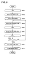
- Figure 8 is a flow chart of the intermittent injection subroutine.
- S201 This is the step of setting the counter N that counts the number of times that the solenoid valve 37 is turned ON and OFF.
- the control unit 99 sets the number X of times for turning ON and OFF specified by the main routine as the initial value in the counter N.
- S202 This is the step of turning ON the micro pump 62.
- the micro pump 62 specified by the main routine is turned ON by the control unit 99 which gives a command to the driving liquid pump driving unit 91.
- S203 This is the step of turning ON the air pump 35.
- the control unit 99 gives a command to the air pump driving unit 94 and turns ON the air pump 35.
- S204 This is the step of turning ON the solenoid valve 37.
- the control unit 99 transmits a control signal to the solenoid valve 37 and turns ON the solenoid valve 37.
- S205 This is the step of waiting for a prescribed time.
- the waiting is done while counting a timer inside the control unit 99.
- the time of the timer is the time at least until a quantity of gas 40 for pushing out the solution 41 injected into the detection unit 111 is injected into the detection unit 111.
- the control unit 99 transmits a control signal to the solenoid valve 37 and turns OFF the solenoid valve 37.
- the counter N is decremented to N-1.
- Step S208 If N is not equal to 0 (NO in Step S208), the operation returns to Step S204.
- Step S208 If N is equal to 0 (YES in Step S208), the operation proceeds to Step S209.
- S209 This is the step of stopping the micro pump 62.
- the control unit 99 stops the micro pump 62 by giving a command to the micro pump driving unit 91.
- S210 This is the step of stopping the air pump 35.
- the control unit 99 stops the air pump 35 by giving a command to the air pump driving unit 94.
- the present invention it is possible to provide a microchip reaction detection system in which it is possible to speed up the progress of a reaction by making a solution flow efficiently with respect to the reacting substance supported on the wall of the flow path of the detection unit, and to provide a reaction method inside the flow path of the microchip.
Landscapes
- Chemical & Material Sciences (AREA)
- Health & Medical Sciences (AREA)
- Dispersion Chemistry (AREA)
- Analytical Chemistry (AREA)
- General Health & Medical Sciences (AREA)
- Clinical Laboratory Science (AREA)
- Hematology (AREA)
- Chemical Kinetics & Catalysis (AREA)
- Physics & Mathematics (AREA)
- Life Sciences & Earth Sciences (AREA)
- Biochemistry (AREA)
- General Physics & Mathematics (AREA)
- Immunology (AREA)
- Pathology (AREA)
- Automatic Analysis And Handling Materials Therefor (AREA)
Abstract
Disclosed is a microchip reaction detection system comprising: a microchip comprising a driving liquid injection unit into which a driving liquid for driving a solution is injected and a detection unit on which a substance to be reacted is supported and where the reaction between the substance and the solution is detected; a driving liquid pump for injecting the driving liquid into the driving liquid injection unit; an air pump for injecting a gas into the detection unit; and a control unit for controlling the driving liquid pump so that the driving liquid can be injected into the driving liquid injection unit and also controlling the air pump so that the gas can be injected into the detection unit intermittently in an amount at least effective for pushing away the solution injected in the detection unit while feeding the solution to the detection unit.
Description
- The present invention relates to microchip reaction detection systems, and to methods of detecting the reactions of microchips in the flow path.
- In recent years, by utilizing micromachining technology and ultra fine machining technology, systems have been developed in which the apparatuses and instruments (for example, pumps, valves, flow paths, sensors, etc.,) for carrying out chemical analysis, chemical synthesis, etc., are miniaturized and integrated on a single chip (see, for example, Patent Document 1). These are also called µ-TAS (Micro Total Analysis Systems), bio reactors, Lab-on-chips, or biochips, and their applications are expected in the fields of medical examination and diagnosis, environmental measurements, and agricultural manufacturing. In reality, as can be seen in gene testing, when complex processes, skilled manipulation, and operation of equipment and instruments are necessary, it can be said that the benefits are high for a micro-miniaturized chemical analysis system that has been automated, is high-speed, and has been simplified because it makes analysis possible without demanding a high cost, necessary quantities of samples, and the required analysis time, but also is not limited to a specific analysis environment or time.
- In various types of analyses and examinations, the quantitative nature of analysis, the accuracy of analysis, and economy, etc., of these chips for analysis (hereinafter, a chip such as the above inside which is provided a fine flow path, and various types of reactions are carried out inside the fine flow paths are called "microchips") are considered important. Because of this, the problem is to establish a liquid flow system having a simple configuration and high reliability, and while micro fluid control devices with high accuracy and superior reliability are required, micro pump systems and methods of their control that are ideally suitable for these have been proposed (Patent Documents 2 to 4).
- Microchips are being used for the amplification and detection of a specific gene in a sample. In such microchips, there are cases in which a reacting substance is supported in advance on the flow path wall surface of the detection unit inside the chip, and by making a plurality of fluids such as reagents flow through this flow path in succession, reactions are carried out by making the supported reacting substance come into contact with these fluids in succession.
- Patent Document 1: Japanese Unexamined Patent Application Publication No.
2004-28589 - Patent Document 2: Japanese Unexamined Patent Application Publication No.
2001-322099 - Patent Document 3: Japanese Unexamined Patent Application Publication No.
2004-108285 - Patent Document 4: Japanese Unexamined Patent Application Publication No.
2004-270537 - However, in a fine flow path of a microchip, a gradient of solution flow is generated in a direction perpendicular to the flow path, and the speed becomes small near the wall surface of the flow path. Further, in the vicinity near the wall surface of the flow path, the speed of the solution effectively becomes 0. Because of this, in a case such as the above in which reactions are carried out by passing solutions through a flow path on the wall surface of which is supported a reacting substance, even if a solution is passed through that flow path, the solution stagnates in the vicinity of the wall surface and there will be no flow. In other words, it becomes difficult to supply a new solution to the reacting substance such as amplified genes supported on the wall of the flow path, and the reaction will not be promoted. Further, even in the case of carrying out reactions by feeding successively different solutions to that flow path, if different solutions such as various reagents are made to flow in succession, there is the problem that the previous solution remains on the wall surface, and the reaction will not progress because the old solution is not replaced by the new solution.
- The present invention was made in view of the above problem, and the purpose of the present invention is to provide a microchip reaction detection system in which it is possible to speed up the progress of a reaction by making a solution flow efficiently with respect to the reacting substance supported on the wall of the flow path of the detection unit, and to provide a reaction method inside the flow path of the microchip.
- The purpose of the present invention can be achieved by the following configuration.
- 1. A microchip reaction detection system with the feature that it comprises: a microchip comprising a driving liquid injection unit into which a driving liquid for driving a solution is injected and a detection unit on which a reacting substance is supported and in which the reaction between said reacting substance and said solution is detected; a driving liquid pump for injecting said driving liquid into said driving liquid injection unit; an air pump for injecting a gas into the detection unit; a control unit for controlling said driving liquid pump so that said driving liquid can be injected into said driving liquid injection unit and also controlling said air pump so that said gas can be injected into said detection unit intermittently of at least an amount effective for pushing away said solution injected into said detection unit while feeding said solution to said detection unit.
- 2. A microchip reaction detection system according to
item 1 above with the feature that said microchip has in the detection unit a flow path for injecting said gas which flow path joins the flow path for feeding said solution. - 3. A method of reaction inside the flow path of a microchip that causes a reaction by feeding a solution to the wall of the flow path supporting a reacting substance in the detection unit thereby making said reacting substance come into contact with said solution, wherein, at the time of causing said reaction, said solution and a gas of at least an amount effective for pushing out the solution injected into said detection unit are alternatively injected into said detection unit.
- 4. A method of reaction inside the flow path of a microchip according to
item 3 above with the feature that the reaction between said reacting substance and said solution is an avidin-biotin reaction. - 5. A method of reaction inside the flow path of a microchip according to
item 3 above with the feature that the reaction between said reacting substance and said solution is a hybridization reaction. - 6. A method of reaction inside the flow path of a microchip according to
item 3 above with the feature that the reaction between said reacting substance and said solution is an antigen antibody reaction. - According to the present invention, since the feeding of liquid-gas-liquid-gas is done to the detection unit in that sequence, and since solutions come into contact with the reacting substance supported on the wall of the flow path of the detection unit intermittently, it is possible to speed up the progress of the reaction.
-
-
Figure 1 is an outline diagram of areaction detection apparatus 80 according to a preferred embodiment of the present invention. -
Figure 2 is an explanatory diagram of amicrochip 1 according to a preferred embodiment of the present invention. -
Figure 3 is an explanatory diagram for explaining the condition when agas 40 of an amount enough for pushing out a solution 41 injected into thedetection unit 111 is alternatively injected into said reaction unit. -
Figure 4 is an explanatory diagram showing an example of the internal construction of areaction detection apparatus 80 according to a preferred embodiment of the present invention. -
Figure 5 is an explanatory diagram showing an example of the construction of a drivingliquid pump 5 according to a preferred embodiment of the present invention. -
Figure 6 is a circuit block diagram of areaction detection apparatus 80 according to a preferred embodiment of the present invention. -
Figure 7 is a flow chart explaining the procedure of testing using areaction detection apparatus 80 according to a preferred embodiment of the present invention. -
Figure 8 is a flow chart of an intermittent injection subroutine for alternatively injecting agas 40 and a solution 41 into thedetection unit 111. -
- 1 Microchip
- 3 Temperature adjusting unit
- 4 Optical detection unit
- 5 Pump
- 6 Packing
- 10 Driving liquid tank
- 11 Driving liquid
- 35 Air pump
- 37 Solenoid valve
- 62 Micro pump
- 80 Reaction detection apparatus
- 82 Chassis
- 83 Insertion inlet
- 84 Display unit
- 110 Driving liquid injection unit
- 111 Detection unit
- 130 Ultra fine flow path
- 113 Unit for injecting specimen that is under examination
- In the following, some preferred embodiments of the present invention are explained with reference to the drawings.
-
Figure 1 is an outline diagram of areaction detection apparatus 80 according to a preferred embodiment of the present invention. - The
reaction detection apparatus 80 is an apparatus that automatically detects the reaction between the specimen under examination that has been injected in advance into themicrochip 1 and a reagent, and displays the results in thedisplay unit 84. - An
insertion inlet 83 is present in thechassis 82 of thereaction detection apparatus 80, and themicrochip 1 is set inside thechassis 82 by inserting it in theinsertion inlet 83. Further, theinsertion inlet 83 has a height that is sufficiently more than the thickness of themicrochip 1 so that themicrochip 1 does not come into contact with theinsertion inlet 83 when it is inserted. Thesymbol 85 is a memory card slot, 86 is a printer output outlet, 87 is an operation panel, and 88 are the input/output pins. - The person in charge of testing inserts the
microchip 1 in the direction of the arrow shown inFigure 1 , and starts the test by operating theoperation panel 87. Inside thereaction detection apparatus 80, the testing of the reaction inside themicrochip 1 is carried out automatically, and when the testing ends, the results are displayed on thedisplay unit 84 configured using an LCD panel, etc. According to operations in theoperation panel 87, the test results can either be printed out via the print outlet 86, or can be stored in a memory card inserted in thememory card slot 85. Further, the data can be stored in a PC, etc., via the external input/output pins 88 using, for example, a LAN cable. - The person in charge of testing, after the testing has ended, takes out the
microchip 1 from theinsertion inlet 83. - Next, an example of the
microchip 1 according to a preferred embodiment of the present invention is explained referring toFigure 2 . -
Figures 2(a) and 2(b) are external view diagrams of amicrochip 1. The arrow mark inFigure 2(a) is the direction of inserting themicrochip 1 in thereaction detection apparatus 80 to be described later, andFigure 2(a) is showing the surface that becomes the bottom surface of themicrochip 1 at the time it is inserted.Figure 2(b) is a side view diagram of themicrochip 1. - The
window 111a of the detection unit and theflow path 111b of the detection unit ofFigure 2(a) have been provided for optically detecting the reaction between the specimen under examination and the reagent, and are made of a transparent material such as glass, or plastic. 110a, 110b, 110c, 110d, and 110e are driving liquid injection units that are connected to the internal fine flow paths, and inject driving liquids from each of the driving liquid injection units 110 and drive the internal reagents, etc. 150 is the gas injection unit that is connected to the internal fine flow path, and gas is injected into the internal fine flow path from thegas injection unit 150. 113 is an injection unit for the specimen under examination that injects the specimen under examination into themicrochip 1. - As is shown in
Figure 2(b) , themicrochip 1 is configured from agrooved substrate 108 and a coveringsubstrate 109 that covers thegrooved substrate 108. - The materials used for the
grooved substrate 108 and the coveringsubstrate 109 that configure themicrochip 1 are explained here. - It is desirable that the
microchip 1 is superior in machining formability, non-water absorbency, chemical resistance, weather resistance, cost, etc., and the material of themicrochip 1 is selected considering the structure, usage, and detection method, etc., of themicrochip 1. As such materials, it is possible to use various materials that are conventionally known, and normally the substrate and the flow path elements are formed by appropriately combining one or more materials according to the individual material characteristics. - In particular, it is desirable that a chip is disposable if it is targeting various types of measured specimens , above all, clinical specimens that have risks of contamination or contagion. Therefore, desirable plastics are ones that can be mass manufactured, are lightweight and strong against shock, and are easy to dispose of by burning, for example, polystyrene which has excellent transparency, mechanical characteristics moldability, and easy micro machinability. Further, for example, when it is necessary to heat the chip during analysis to near 100 °C, it is desirable to use a plastic material (for example, polycarbonate) that is superior in the ability to withstand heat. In addition, when the adhesion of proteins becomes a problem, it is desirable to use polypropylene. Plastics and glass have small thermal conductivity, and by using these materials in regions of the microchip which are locally heated, it is possible to suppress heat transmission in the surface direction, and to heat the area to be heated selectively.
- In the present preferred embodiment, in the
detection unit 111, since the detection of products of color change reaction or fluorescent materials is done optically, it is necessary to make the substrate, at least in these parts, transparent using an optically transparent material (for example, alkali glass, quartz glass, transparent plastics, etc.) so that light is allowed to pass through. In the present preferred embodiment, thedetection unit 111 is made transparent to light by using a light transmitting material for the grooved substrate in which thewindow 111a of the detection unit and at least theflow path 111b of the detection unit are formed. - In the
microchip 1 according to a preferred embodiment of the present invention, in order to carry out testing, specimen processing, etc., fine groove shaped flow paths (fine flow paths) and functional components (flow path elements) have been placed in appropriate forms according to the application. An example of processing in the present preferred embodiment for carrying out the specific gene amplification and their detection carried out using these fine flow paths and flow path elements inside themicrochip 1 is explained here referring toFigure 2(c) . However, the application of the present invention is not restricted to the example of the microchip explained usingFigure 2(c) , and can be applied tomicrochips 1 for various applications. -
Figure 2(c) is an explanatory diagram for explaining the functions of the fine flow path and flow path elements inside amicrochip 1. - In the fine flow path are provided, for example, a
storage unit 121 for the specimen under examination which stores the specimen under examination, a reagent storage unit 120 for storing the reagent, etc., and, so that testing can be done speedily without requiring a specific place or time, the necessary varieties of reagents, cleaning liquid, denaturization processing liquid, etc., are stored in advance in the reagent storage unit 120. InFigure 2(c) , the reagent storage unit 120, thestorage unit 121 for the specimen under examination, the flow path elements shown by rectangles, and the fine flow paths between them are shown by continuous lines and arrows. - The
microchip 1 is configured from agrooved substrate 108 in which are formed fine flow paths and a coveringsubstrate 109 that covers the groove shaped flow paths. The fine flow paths are formed with micrometer order dimensions, and, for example, the width is from several µm to several hundreds of µm, desirably, 10 to 200 µm, depth are from about 25 to 500 µm, and desirably, 25 to 250 µm. - The above fine flow paths are formed at least in the
grooved substrate 108 of themicrochip 1. It is necessary that the coveringsubstrate 109 covers by coming in close contact with at least the fine flow paths of the grooved substrate, and desirably should cover the entire grooved substrate. Further, in the fine flow paths of themicrochip 1 are provided parts for controlling the flow of the liquids such as, for example, flow control units not shown in the figure, reverse flow prevention units (reverse flow prevention valves, active valves, etc.,), etc., so that reverse flow is prevented, and the liquid flow is carried out in a prescribed sequence. - The
injection unit 113 for the specimen under examination is an injection unit for injecting the specimen under examination into themicrochip 1, and the driving liquid injection unit 110 is an injection unit for injecting the driving liquid 11 into themicrochip 1. Before carrying out testing using themicrochip 1, the person in charge of testing injects the specimen under examination using a syringe, etc., via theinjection unit 113 for the specimen under examination. As is shown inFigure 2(c) , the specimen under examination injected from theinjection unit 113 for the specimen under examination passes through the connected fine flow paths and is stored in thestorage unit 121 for the specimen under examination. - Next, when the driving liquid 11 is injected from the driving
liquid injection unit 110a, the driving liquid 11 passes through the connected fine flow path and pushes out the specimen under examination stored in thestorage unit 121 for the specimen under examination, and feeds the specimen under examination into theamplification unit 122. - On the other hand, the driving liquid 11 injected from the driving
liquid injection unit 110b pushes out the reagent stored in thereagent storage unit 120a via the connected fine flow path. The reagent pushed out from thereagent storage unit 120a is fed to theamplification unit 122 by the driving liquid 11. Depending on the reaction conditions at this time, it is necessary to take theamplification unit 122 to a prescribed temperature, and as described later, the reaction is made at the prescribed temperature by heating or heat absorption inside thereaction detection apparatus 80. - After the prescribed reaction time, a
solution 41a that includes the specimen under examination after reaction and fed from theamplification unit 122 by an additional driving liquid 11 is injected into thedetection unit 111. The injectedsolution 41a reacts with the reacting substance supported on the wall of the flow path of thedetection unit 111 and gets fixed on the wall of the flow path. - On the other hand, during that period, a
gas 40 such as air of a quantity sufficient to push out thesolution 41a injected into thedetection unit 111 is injected into thedetection unit 111 from thegas injection unit 150 at prescribed time intervals. As a consequence, thegas 40 pushes out thesolution 41a injected into thedetection unit 111 to the wasteliquid storage unit 125, and thedetection unit 111 temporarily becomes empty. When the injection ofgas 40 is completed, afresh solution 41a, which includes the specimen under examination after reaction, is injected into thedetection unit 111 by the driving liquid 11. Thefresh liquid 41a that has been injected reacts with the reacting substance supported on the wall of the flow path of thedetection unit 111 and gets fixed on the wall of the flow path. By carrying out processing in this manner, sincefresh solutions 41a are injected successively into thedetection unit 111, it is possible to speed up the progress of the reaction with the reacting substance supported on the wall of the flow path. - In the present preferred embodiment, the reagent a is a primer modified by a biotin, carries out gene amplification of the specimen under examination in the
amplification unit 122, and a specimen under examination after reaction in which the amplified genes are converted to single chains by denaturalization processing is fed to thedetection unit 111. A biotin-affine protein such as streptavidin, etc., is supported and is fixed on the wall of the flow path of thedetection unit 111 in advance as the reacting substance. When the specimen under examination after reaction in theamplification unit 122 flows into thedetection unit 111, because of a coupling reaction between the biotin-affine protein and biotin, the genes in the specimen under examination are fixed on the wall of the flow path of thedetection unit 111. Said coupling reaction between biotin-affine protein and biotin is a publicly known avidin-biotin reaction. -
Figure 3 is an explanatory diagram for explaining the condition when asolution 41a injected into thedetection unit 111 and agas 40 of an amount enough for pushing out saidsolution 41a are alternatively injected into saiddetection unit 111. Here, 130a is the fine flow path from thegas injection unit 150. Further, 130b, 130c, 130d, and 130e are the fine flow paths, respectively, from theamplification unit 122, thereagent storage unit 120b, thereagent storage unit 120c, and the cleaningliquid storage unit 123. Afine flow path 130f is connected between the outlet of thedetection unit 111 and the wasteliquid storage unit 125.Water repellent valves fine flow paths fine flow path 130b. Since a gas such as air is present at the parts of the water repellent valves 131, thesolution 41a will never get mixed with other solutions. - To begin with, explanation is given about
Figure 3(a) . Thesolution 41a which includes the specimen under examination and which is fed after reaction from theamplification unit 122 is passed through thefine flow path 130b and is injected in the direction of the arrow into thedetection unit 111. When the inside of thedetection unit 111 is full of thesolution 41a,gas 40 is injected from thefine flow path 130a at prescribed time intervals. As a result,gas 40 pushes out thesolution 41a to the wasteliquid storage unit 125, and thedetection unit 111 becomes temporarily empty. When the injection ofgas 40 ends, afresh solution 41b which includes the specimen under examination after reaction is injected by the driving liquid 11 into thedetection unit 111. In other words, while thesolution 41a is being driven by the driving liquid 11, an amount of gas necessary to push out thesolution 41a injected into thedetection unit 111 is injected intermittently. By doing so in this manner, as is shown inFigure 3(a) , gas 40-solution 41a-gas 40-solution 41a are successively injected in that sequence into thedetection unit 111 and discharged to the wasteliquid storage unit 125 via thefine flow path 130f. The injectedfresh solution 41a reacts with the reacting substance that is supported on the wall of the flow path of thedetection unit 111 and the genes in the specimen under examination are fixed on the wall of the flow path. By doing so in this manner, since successivelyfresh solutions 41a are injected into thedetection unit 111 intermittently while replacing each other, it is possible to speed up the progress of the reaction between the reacting substance that is supported on the wall of the flow path and the genes of the specimen under examination. - After carrying out the reaction between the reacting substance and the
solution 41a in thedetection unit 111, next a reaction is caused after injecting reagent b into thedetection unit 111. This operation is explained referring toFigure 3(b) . - Before injecting reagent b, as is shown in
Figure 3(b) ,sufficient gas 40 is fed from thefine flow path 130a thereby making thesolution 41a recede inside thefine flow path 130b in a direction opposite to that of the arrow. - Next, when the driving liquid 11 is injected from the driving
liquid injection unit 110c, the driving liquid 11 passes through the connected flow path and pushes out the reagent b stored in thereagent storage unit 120b, and injects thesolution 41b which is the reagent b into thedetection unit 111 via thefine flow path 130c. - On the other hand, during that period a
gas 40 such as air of at least an amount necessary to push out thesolution 41b injected into thedetection unit 111 is intermittently injected from thegas injection unit 150 into thedetection unit 111 at prescribed intervals of time. As a result,gas 40 pushes out thesolution 41b to the wasteliquid storage unit 125, and thedetection unit 111 becomes temporarily empty. When the injection ofgas 40 ends, afresh solution 41b, which includes the specimen under examination after reaction, is injected into thedetection unit 111 by the driving liquid 11. The injectedfresh solution 41b reacts with the reacting substance that is supported on the wall of the flow path of thedetection unit 111 and the reacting substance included in thesolution 41b is fixed on the wall of the flow path. By doing so in this manner, since successivelyfresh solutions 41b are injected into thedetection unit 111 intermittently while replacing each other, it is possible to speed up the progress of the reaction between the reacting substance that is supported on the wall of the flow path and the reacting substance that is included in thesolution 41b. - In the present preferred embodiment, solution b is a probe DNA whose ends are fluorescently labeled by FITC, and is hybridized with the genes fixed on the wall of the flow path of the
detection unit 111 by injecting reagent b into thedetection unit 111. This method is a well known hybridization reaction. - After carrying out the reaction between the reacting substance in the
detection unit 111 and thesolution 41b in this manner, in a similar manner, reagent c is injected into thedetection unit 111 alternating with agas 40 from thefine flow path 130d and reacted. - In the present preferred embodiment, reagent c is a surface modified gold colloid liquid which is an anti-FITC antibody that links specifically, and the FITC modified probe fixed on the surface of the wall of the flow path of the
detection unit 111 by injecting the reagent c into thedetection unit 111 causes adhesion of the gold colloid to the hybridized gene. This method is a well known antigen antibody reaction. - Finally, in a similar procedure, a cleaning
liquid 47 is injected into thedetection unit 111 via thefine flow path 130e thereby cleaning the unreacted solution 41 remaining in thedetection unit 111. - After cleaning, the amplified gene is detected by optically measuring the density of the gold colloid adhered to the flow path wall of the
detection unit 111. -
Figure 4 is an explanatory diagram showing an example of the internal construction of areaction detection apparatus 80 according to a preferred embodiment of the present invention. Thedetection apparatus 80 is configured to have atemperature adjustment unit 3, an optical detection unit 4, a drivingliquid pump 5, anair pump 35, a packing 6, and a drivingliquid tank 10, etc. In the following, the constituent elements similar to the constituent elements described so far are assigned the same numbers and their explanations will be omitted. -
Figure 4 is a condition in which the top surface of themicrochip 1 is in close contact with thetemperature adjustment unit 3 and the packing 6. Thetemperature adjustment unit 3 and the packing 6 are driven by driving members not shown in the figure and can be moved in the up-down direction with respect to the surface of the paper. - In the initial condition, the
temperature adjustment unit 3 and the packing 6 are raised by the driving members by an amount more than the thickness of themicrochip 1 from the condition shown inFigure 4 . As a result, themicrochip 1 can be inserted and withdrawn in the direction of the arrow inFigure 4 , and the person in charge of testing inserts themicrochip 1 through theinsertion inlet 83 until it butts against a restricting member not shown in the figure. When themicrochip 1 is inserted up to the prescribed position, achip detection unit 95 issuing a photo interrupter, etc., turns ON when themicrochip 1 is detected. - The
temperature adjustment unit 3 has in it a Peltier device, a power supply unit, a temperature controller unit, etc., and is a unit that adjusts the top surface of themicrochip 1 to a prescribed temperature by heating or heat absorption. - Next, the
temperature adjustment unit 3 and the packing 6 are lowered by the driving members making the top surface of themicrochip 1 come into close contact with thetemperature adjustment unit 3 and the packing 6. - In the
detection unit 111 of themicrochip 1, the specimen under examination and the reacting substance that is stored inside saidmicrochip 1 react with each other and cause, for example, color change, light emission, fluorescence, turbidization, etc. In the present preferred embodiment, the result of the reaction of the reagent occurring in thedetection unit 111 is detected optically through thewindow 111a of the detection unit. Thegrooved substrate 108 and the coveringsubstrate 109 forming thedetection unit 111 of themicrochip 1 that optically measures the result of the reaction with the reagent are made of a material that is transparent to light, and the result of the reaction between the reagent and the specimen under examination can be analyzed by measuring the light or by measuring the color of the light passing through thedetection unit 111 of themicrochip 1. - The optical detection unit 4 is comprised of a
light emitting unit 4a and alight receiving unit 4b, and is placed so that it is possible to detect the light passing through thedetection unit 111 of themicrochip 1. - The
air pump 35 is a pump that feeds agas 40 such as air at a prescribed pressure, and thegas 40 blowing outlet is connected to the packing 6 by ahose 36 with asolenoid valve 37 in between. The gas blow outlet of thehose 36, the opening in the packing 6, and thegas injection unit 150 are connected with each other. Thegas 40 fed from the hole connecting the packing 6 and thehose 36 is injected into thefine flow path 130a formed inside themicrochip 1 via the connectedgas injection unit 150 of themicrochip 1. Thesolenoid valve 37 controls the ON and OFF of the supply of gas according to the commands from the control unit 99 (seeFigure 6 ). In this manner, agas 40 can be intermittently injected from theair pump 35 into thefine flow path 130a via the connected packing 6. - A
suction inlet 12 is connected to the suction side of the drivingliquid pump 5 so that it is possible to suck the driving liquid 11 stored in the drivingliquid tank 10. On the other hand, a packing 6 is connected to the outlet side of the drivingliquid pump 5, and the driving liquid 11 sucked in from thesuction inlet 12 is injected into the fine flow path formed inside themicrochip 1 from the driving liquid injection unit 110 of themicrochip 1 via the packing 6. The packing 6 is clasped in between the drivingliquid pump 5 and themicrochip 1, the driving liquid outlet of the drivingliquid pump 5, the opening of the packing 6, the driving liquid injection unit 110 are connected with each other. In this manner, the driving liquid 11 from the drivingliquid pump 5 and passing through the packing 6 is injected from the driving liquid injection unit 110. - Next the driving
liquid pump 5 is explained referring toFigure 5 . -
Figure 5 is an explanatory diagram showing an example of the construction of the drivingliquid pump 5 according to a preferred embodiment of the present invention. - This driving
liquid pump 5 is configured to have three substrates of asubstrate 67 made of silicon, aglass substrate 68 on top of it, and anotherglass substrate 69 on top of that. Thesubstrate 67 and thesubstrate 68 are anodic bonded, and thesubstrate 68 andsubstrate 69 are bonded together either by adhesive bonding or by fusion bonding. - A micro pump 62 (piezo pump) is formed in the internal space between the
substrate 67 made of silicon and theglass substrate 68 which is fixed on top of it by anodic bonding. An example of the drive source of themicro pump 62 is a piezoelectric device, and the liquid is sent in the direction from left to right inFigure 5 by changing the volume of the internal pressure chamber. - The upstream side of the
micro pump 62 is connected to theopening 64 provided in the glass substrate from the flow path provided in thesubstrate 67 via the penetratinghole 66a of thesubstrate 68. Theopening 64 is connected to the drivingliquid tank 10 via thesuction inlet 12, so that the driving liquid 11 stored in the drivingliquid tank 10 is sucked in. - A
flow path 70 has been patterned in thesubstrate 69. As an example, the dimensions and shape of theflow path 70 are - a rectangular cross-section with a width of about 150 µm and a depth of about 300 µm. An opening 65 is provided on the downstream side of theflow path 70, and the liquid is fed by themicro pump 62 via theflow path 70. The packing 6 is provided with an opening matching with the position of the opening 65 when the drivingliquid pump 5 and the packing 6 come into close contact with each other. Further, since openings are also provided in the packing 6 matching with the positions of the driving liquid injection unit 110 and the specimen underexamination injection unit 113 when the packing 6 and themicrochip 1 come into close contact with each other, it is possible to inject the driving liquid from eachmicro pump 62 to the driving liquid injection unit 110 and the specimen underexamination injecting unit 113. -
Figure 6 is a circuit block diagram of thereaction detection apparatus 80 according to a preferred embodiment of the present invention. - The
control unit 99 is configured to have a CPU 98 (Central Processing Unit), a RAM (Random Access Memory) 97, a ROM (Read Only Memory) 96, etc., the programs stored in theROM 96 which is a non-volatile type storage unit are read into theRAM 97, and different sections of thereaction detection apparatus 80 are centrally controlled in accordance with these programs. - In the following, the functional blocks having the same functions as those described so far are assigned the same numbers and their explanations are omitted.
- The
chip detection unit 95 transmits a detection signal to theCPU 98 when amicrochip 1 butts against the restricting member. The driving liquidpump driving unit 91 is a driving unit that drives the different drive sources, for example, piezoelectric devices, inside the drivingliquid pump 5. The airpump driving unit 94 is a drive circuit that drives theair pump 35 in accordance with the commands from thecontrol unit 99. Thememory card 92 is used for storing the test results, and theprinter 93 is used for printing out the test results. -
Figure 7 is a flow chart explaining the procedure for testing in thereaction detection apparatus 80 in a preferred embodiment of the present invention. - However, it is assumed that power is supplied to the
temperature adjustment unit 3 at the time that the power supply to thereaction detection apparatus 80 is switched ON, and the prescribed temperature has been reached. Further, it is assumed that, before the testing, the driving liquid 11 has been filled up to the top end of the packing 6. - S101: This is the step of inserting the
microchip 1. - The person in charge of testing inserts the
microchip 1 into theinsertion inlet 83 until it butts against a restricting member not shown in the figure (not in the figure). - S102: This is the step of lowering the mechanism.
- When the
microchip 1 inserted into theinsertion inlet 83 butts against the restricting member, and theCPU 98 detects the detection signal from thechip detection unit 95, thecontrol unit 99 controls themechanism driving unit 32, and lowers until there is close contact with an appropriate pressure with the packing 6 and thetemperature control unit 3. - S103: This is the step of injecting the reagent a and the specimen under examination into the
amplification unit 122. - The
control unit 99 commands the driving liquidpump driving unit 91, and successively injects prescribed quantities of the driving liquid 11 by driving themicro pump 62 connected with the drivingliquid injection unit 110a and the micro pump connected with the drivingliquid injection unit 110b. As was explained regardingFigure 2 , because of the driving liquid 11, the reagent a and the specimen under examination are fed to theamplification unit 122 and react there. - S104: This is the step of injecting the
solution 41a into thedetection unit 111. - After a prescribed reaction time, the
control unit 99 calls the intermittent injection subroutine, and alternatively injects thesolution 41a that has the specimen under examination after reaction andgas 40 into thedetection unit 111. - S105: This is the step of suctioning the
solution 41a from thefine flow path 130. - The
control unit 99 commands the driving liquidpump driving unit 91, and drives themicro pump 62 connected to the drivingliquid injection unit 110a in the reverse direction, and recedes the driving liquid 11 up to the position shown inFigure 3(b) . - S106: This is the step of injecting the
solution 41b into thedetection unit 111. - After a prescribed reaction time, the
control unit 99 calls the intermittent injection subroutine, and alternatively injects thesolution 41b that has the specimen under examination after reaction andgas 40 into thedetection unit 111. - S107: This is the step of injecting the
solution 41c into thedetection unit 111. - After a prescribed reaction time, the
control unit 99 calls the intermittent injection subroutine, and alternatively injects thesolution 41c that has the specimen under examination after reaction andgas 40 into thedetection unit 111. - S108: This is the step of injecting the cleaning
liquid 47 into thedetection unit 111. - After a prescribed reaction time, the
control unit 99 calls the intermittent injection subroutine, and alternatively injects the cleaning liquid andgas 40 into thedetection unit 111. - S109: This is the step of detecting the results of the reaction in the
detection unit 111. - After a prescribed reaction time, the
control unit 99 illuminates thedetection unit 111 of themicrochip 1 by making thelight emitting unit 4a emit light, and obtains the measured light value by converting the input signal from thelight receiving unit 4b that has received the transmitted light that has been transmitted through thedetection unit 111 into a digital value using the A/D converter incorporated inside theCPU 98. - S110: This is the step of displaying the reaction results.
- The
control unit 99 carries out computation from the result of light measurement made by the optical detection unit 4, and displays the reaction results on thedisplay unit 84. - This is the end of the testing procedure.
- Next, referring to
Figure 8 , the procedure of the intermittent injection subroutine that causes the alternating injection ofgas 40 and solution 41 into thedetection unit 111 is explained here.Figure 8 is a flow chart of the intermittent injection subroutine. - S201: This is the step of setting the counter N that counts the number of times that the
solenoid valve 37 is turned ON and OFF. - The
control unit 99 sets the number X of times for turning ON and OFF specified by the main routine as the initial value in the counter N. - S202: This is the step of turning ON the
micro pump 62. - The
micro pump 62 specified by the main routine is turned ON by thecontrol unit 99 which gives a command to the driving liquidpump driving unit 91. - S203: This is the step of turning ON the
air pump 35. - The
control unit 99 gives a command to the airpump driving unit 94 and turns ON theair pump 35. - S204: This is the step of turning ON the
solenoid valve 37. - The
control unit 99 transmits a control signal to thesolenoid valve 37 and turns ON thesolenoid valve 37. - S205: This is the step of waiting for a prescribed time.
- The waiting is done while counting a timer inside the
control unit 99. The time of the timer is the time at least until a quantity ofgas 40 for pushing out the solution 41 injected into thedetection unit 111 is injected into thedetection unit 111. - S206: This is the step of turning OFF the
solenoid valve 37. - The
control unit 99 transmits a control signal to thesolenoid valve 37 and turns OFF thesolenoid valve 37. - S207: This is the step of decrementing N (making N=N-1).
- The counter N is decremented to N-1.
- S208: This is the step of judging whether N=0.
- If N is not equal to 0 (NO in Step S208), the operation returns to Step S204.
- If N is equal to 0 (YES in Step S208), the operation proceeds to Step S209.
- S209: This is the step of stopping the
micro pump 62. - The
control unit 99 stops themicro pump 62 by giving a command to the micropump driving unit 91. - S210: This is the step of stopping the
air pump 35. - The
control unit 99 stops theair pump 35 by giving a command to the airpump driving unit 94. - The above ends the subroutine and the program execution returns to the main routine.
- As has been explained above, according to the present invention, it is possible to provide a microchip reaction detection system in which it is possible to speed up the progress of a reaction by making a solution flow efficiently with respect to the reacting substance supported on the wall of the flow path of the detection unit, and to provide a reaction method inside the flow path of the microchip.
Claims (6)
- A microchip reaction detection system comprising:a microchip comprisinga driving liquid injection unit into which a driving liquid for driving a solution is injected anda detection unit on which a reacting substance is supported and in which the reaction between the reacting substance and the solution is detected;a driving liquid pump for injecting the driving liquid into the driving liquid injection unit;an air pump for injecting a gas into the detection unit; anda control unitfor controlling the driving liquid pump so that the driving liquid can be injected into the driving liquid injection unit and controlling the air pump so that the gas can be injected into the detection unit intermittently of at least an amount effective for pushing away the solution injected into the detection unit while feeding the solution to the detection unit.
- The microchip reaction detection system of Claim 1,
wherein the microchip has a flow path for injecting the gas which flow path joins a flow path for feeding the solution at the detection unit. - A method of reaction inside a flow path of a microchip,
wherein the reaction is carried out
by feeding a solution to a wall of a flow path which supports a reacting substance in the detection unit and
by contacting the reacting substance with the solution, and
wherein the solution and a gas of at least an amount effective for pushing out the solution injected into the detection unit are alternatively injected into the detection unit at the time of the reaction. - The method of reaction inside the flow path of the microchip of Claim 3,
wherein the reaction between the reacting substance and the solution is an avidin-biotin reaction. - The method of reaction inside the flow path of the microchip of Claim 3,
wherein the reaction between the reacting substance and the solution is a hybridization reaction. - The method of reaction inside the flow path of the microchip of Claim 3,
wherein the reaction between the reacting substance and the solution is an antigen antibody reaction.
Applications Claiming Priority (2)
| Application Number | Priority Date | Filing Date | Title |
|---|---|---|---|
| JP2006283542 | 2006-10-18 | ||
| PCT/JP2007/068469 WO2008047533A1 (en) | 2006-10-18 | 2007-09-22 | Microchip reaction detection system, and method of reaction of microchip in flow path |
Publications (1)
| Publication Number | Publication Date |
|---|---|
| EP2075585A1 true EP2075585A1 (en) | 2009-07-01 |
Family
ID=39313782
Family Applications (1)
| Application Number | Title | Priority Date | Filing Date |
|---|---|---|---|
| EP07807798A Withdrawn EP2075585A1 (en) | 2006-10-18 | 2007-09-22 | Microchip reaction detection system, and method of reaction of microchip in flow path |
Country Status (4)
| Country | Link |
|---|---|
| US (1) | US20100304498A1 (en) |
| EP (1) | EP2075585A1 (en) |
| JP (1) | JPWO2008047533A1 (en) |
| WO (1) | WO2008047533A1 (en) |
Families Citing this family (5)
| Publication number | Priority date | Publication date | Assignee | Title |
|---|---|---|---|---|
| CN112119311B (en) * | 2018-07-27 | 2024-12-20 | 泽普托生命技术股份有限公司 | Systems and methods for processing analyte signals in GMR-based biomarker detection |
| CN110346585A (en) * | 2019-07-10 | 2019-10-18 | 深圳金迈隆电子技术有限公司 | A kind of on piece laboratory testing method and system |
| EP4087625A4 (en) | 2020-01-08 | 2024-03-13 | Zepto Life Technology, LLC | POLYMER COMPOSITIONS AND BIOSURFACES CONTAINING SAME ON SENSORS |
| CN113125693B (en) * | 2021-03-08 | 2022-09-16 | 中山大学 | Small-sized portable full-automatic enzyme-linked immunoassay analyzer and application thereof |
| CN115389751B (en) * | 2021-05-24 | 2025-01-28 | 广州万孚生物技术股份有限公司 | Biological detection cartridges and medical detection systems |
Family Cites Families (8)
| Publication number | Priority date | Publication date | Assignee | Title |
|---|---|---|---|---|
| JPS6276664U (en) * | 1985-11-01 | 1987-05-16 | ||
| JP2001310465A (en) * | 2000-04-28 | 2001-11-06 | Fuji Photo Film Co Ltd | Method for splitting gas-liquid phase, phase splitter, method of forming image, and image forming apparatus |
| JP3629405B2 (en) | 2000-05-16 | 2005-03-16 | コニカミノルタホールディングス株式会社 | Micro pump |
| JP4106977B2 (en) | 2002-06-21 | 2008-06-25 | 株式会社日立製作所 | Analysis chip and analyzer |
| JP3725109B2 (en) | 2002-09-19 | 2005-12-07 | 財団法人生産技術研究奨励会 | Microfluidic device |
| JP3988658B2 (en) | 2003-03-07 | 2007-10-10 | コニカミノルタホールディングス株式会社 | Micropump control method and microfluidic system |
| US7247487B2 (en) * | 2003-06-18 | 2007-07-24 | Ortho-Clinical Diagnostics | Reducing working fluid dilution in liquid systems |
| US7665303B2 (en) * | 2004-03-31 | 2010-02-23 | Lifescan Scotland, Ltd. | Method of segregating a bolus of fluid using a pneumatic actuator in a fluid handling circuit |
-
2007
- 2007-09-22 US US12/445,709 patent/US20100304498A1/en not_active Abandoned
- 2007-09-22 EP EP07807798A patent/EP2075585A1/en not_active Withdrawn
- 2007-09-22 JP JP2008539702A patent/JPWO2008047533A1/en not_active Withdrawn
- 2007-09-22 WO PCT/JP2007/068469 patent/WO2008047533A1/en not_active Ceased
Non-Patent Citations (1)
| Title |
|---|
| See references of WO2008047533A1 * |
Also Published As
| Publication number | Publication date |
|---|---|
| WO2008047533A1 (en) | 2008-04-24 |
| US20100304498A1 (en) | 2010-12-02 |
| JPWO2008047533A1 (en) | 2010-02-25 |
Similar Documents
| Publication | Publication Date | Title |
|---|---|---|
| US7482585B2 (en) | Testing chip and micro integrated analysis system | |
| JP4543986B2 (en) | Micro total analysis system | |
| EP2597472A2 (en) | Micro integrated analysis system, testing chip, and testing method | |
| US20180221878A1 (en) | Specimen treatment chip, specimen treatment apparatus, and specimen treatment method | |
| US20180345289A1 (en) | Specimen processing chip, liquid feeder and liquid feeding method of specimen processing chip | |
| EP3175222B1 (en) | Device for detecting a level of an analyte in a sample | |
| EP2075585A1 (en) | Microchip reaction detection system, and method of reaction of microchip in flow path | |
| WO2012111429A1 (en) | Flow passage device and method of transporting liquid using the same | |
| US20060239862A1 (en) | Testing chip and micro analysis system | |
| EP1925366A1 (en) | Microchip inspection system and microchip inspection system program | |
| WO2005070533A1 (en) | System for characterising a fluid, microfluidic device for characterising or analysing concentrations components, a method of characterising or analysing such concentrations and a measurement | |
| JP2007120399A (en) | Micro fluid chip and micro comprehensive analysis system | |
| JPWO2008087828A1 (en) | Microchip | |
| WO2008053660A1 (en) | Micropump unit, and microchip inspection system | |
| US8021629B2 (en) | Analyzer | |
| JP4687413B2 (en) | Method for mixing two or more liquids in a microchip and a micro total analysis system | |
| JP2009150809A (en) | Microchip | |
| JP2009222479A (en) | Inspection device | |
| CN101146607A (en) | Backflow prevention structure, inspection microchip using same, and inspection device | |
| JP2009058352A (en) | Inspection apparatus | |
| EP2034317A1 (en) | Micro general analysis system with mechanism for preventing leakage of liquid | |
| JP5182368B2 (en) | Micro inspection chip, inspection apparatus, and driving method of micro inspection chip | |
| JP2006284451A (en) | Micro total analysis system for analyzing target material in specimen | |
| JPWO2008065911A1 (en) | Microchip | |
| JP4604834B2 (en) | Microchip for inspection and inspection apparatus using the same |
Legal Events
| Date | Code | Title | Description |
|---|---|---|---|
| PUAI | Public reference made under article 153(3) epc to a published international application that has entered the european phase |
Free format text: ORIGINAL CODE: 0009012 |
|
| 17P | Request for examination filed |
Effective date: 20090416 |
|
| AK | Designated contracting states |
Kind code of ref document: A1 Designated state(s): AT BE BG CH CY CZ DE DK EE ES FI FR GB GR HU IE IS IT LI LT LU LV MC MT NL PL PT RO SE SI SK TR |
|
| AX | Request for extension of the european patent |
Extension state: AL BA HR MK RS |
|
| STAA | Information on the status of an ep patent application or granted ep patent |
Free format text: STATUS: THE APPLICATION HAS BEEN WITHDRAWN |
|
| 18W | Application withdrawn |
Effective date: 20110527 |