EP2075465B1 - Vorrichtung und Verfahren zur individuellen Messung des Schalls bei Blättern einer Windenergieanlage - Google Patents
Vorrichtung und Verfahren zur individuellen Messung des Schalls bei Blättern einer Windenergieanlage Download PDFInfo
- Publication number
- EP2075465B1 EP2075465B1 EP08171653.2A EP08171653A EP2075465B1 EP 2075465 B1 EP2075465 B1 EP 2075465B1 EP 08171653 A EP08171653 A EP 08171653A EP 2075465 B1 EP2075465 B1 EP 2075465B1
- Authority
- EP
- European Patent Office
- Prior art keywords
- blades
- noise
- blade
- wind turbine
- noise level
- Prior art date
- Legal status (The legal status is an assumption and is not a legal conclusion. Google has not performed a legal analysis and makes no representation as to the accuracy of the status listed.)
- Active
Links
Images



Classifications
-
- F—MECHANICAL ENGINEERING; LIGHTING; HEATING; WEAPONS; BLASTING
- F03—MACHINES OR ENGINES FOR LIQUIDS; WIND, SPRING, OR WEIGHT MOTORS; PRODUCING MECHANICAL POWER OR A REACTIVE PROPULSIVE THRUST, NOT OTHERWISE PROVIDED FOR
- F03D—WIND MOTORS
- F03D7/00—Controlling wind motors
- F03D7/02—Controlling wind motors the wind motors having rotation axis substantially parallel to the air flow entering the rotor
- F03D7/022—Adjusting aerodynamic properties of the blades
- F03D7/024—Adjusting aerodynamic properties of the blades of individual blades
-
- F—MECHANICAL ENGINEERING; LIGHTING; HEATING; WEAPONS; BLASTING
- F03—MACHINES OR ENGINES FOR LIQUIDS; WIND, SPRING, OR WEIGHT MOTORS; PRODUCING MECHANICAL POWER OR A REACTIVE PROPULSIVE THRUST, NOT OTHERWISE PROVIDED FOR
- F03D—WIND MOTORS
- F03D17/00—Monitoring or testing of wind motors, e.g. diagnostics
-
- F—MECHANICAL ENGINEERING; LIGHTING; HEATING; WEAPONS; BLASTING
- F03—MACHINES OR ENGINES FOR LIQUIDS; WIND, SPRING, OR WEIGHT MOTORS; PRODUCING MECHANICAL POWER OR A REACTIVE PROPULSIVE THRUST, NOT OTHERWISE PROVIDED FOR
- F03D—WIND MOTORS
- F03D7/00—Controlling wind motors
- F03D7/02—Controlling wind motors the wind motors having rotation axis substantially parallel to the air flow entering the rotor
- F03D7/0296—Controlling wind motors the wind motors having rotation axis substantially parallel to the air flow entering the rotor to prevent, counteract or reduce noise emissions
-
- F—MECHANICAL ENGINEERING; LIGHTING; HEATING; WEAPONS; BLASTING
- F05—INDEXING SCHEMES RELATING TO ENGINES OR PUMPS IN VARIOUS SUBCLASSES OF CLASSES F01-F04
- F05B—INDEXING SCHEME RELATING TO WIND, SPRING, WEIGHT, INERTIA OR LIKE MOTORS, TO MACHINES OR ENGINES FOR LIQUIDS COVERED BY SUBCLASSES F03B, F03D AND F03G
- F05B2260/00—Function
- F05B2260/96—Preventing, counteracting or reducing vibration or noise
-
- F—MECHANICAL ENGINEERING; LIGHTING; HEATING; WEAPONS; BLASTING
- F05—INDEXING SCHEMES RELATING TO ENGINES OR PUMPS IN VARIOUS SUBCLASSES OF CLASSES F01-F04
- F05B—INDEXING SCHEME RELATING TO WIND, SPRING, WEIGHT, INERTIA OR LIKE MOTORS, TO MACHINES OR ENGINES FOR LIQUIDS COVERED BY SUBCLASSES F03B, F03D AND F03G
- F05B2270/00—Control
- F05B2270/30—Control parameters, e.g. input parameters
- F05B2270/326—Rotor angle
-
- F—MECHANICAL ENGINEERING; LIGHTING; HEATING; WEAPONS; BLASTING
- F05—INDEXING SCHEMES RELATING TO ENGINES OR PUMPS IN VARIOUS SUBCLASSES OF CLASSES F01-F04
- F05B—INDEXING SCHEME RELATING TO WIND, SPRING, WEIGHT, INERTIA OR LIKE MOTORS, TO MACHINES OR ENGINES FOR LIQUIDS COVERED BY SUBCLASSES F03B, F03D AND F03G
- F05B2270/00—Control
- F05B2270/30—Control parameters, e.g. input parameters
- F05B2270/333—Noise or sound levels
-
- Y—GENERAL TAGGING OF NEW TECHNOLOGICAL DEVELOPMENTS; GENERAL TAGGING OF CROSS-SECTIONAL TECHNOLOGIES SPANNING OVER SEVERAL SECTIONS OF THE IPC; TECHNICAL SUBJECTS COVERED BY FORMER USPC CROSS-REFERENCE ART COLLECTIONS [XRACs] AND DIGESTS
- Y02—TECHNOLOGIES OR APPLICATIONS FOR MITIGATION OR ADAPTATION AGAINST CLIMATE CHANGE
- Y02E—REDUCTION OF GREENHOUSE GAS [GHG] EMISSIONS, RELATED TO ENERGY GENERATION, TRANSMISSION OR DISTRIBUTION
- Y02E10/00—Energy generation through renewable energy sources
- Y02E10/70—Wind energy
- Y02E10/72—Wind turbines with rotation axis in wind direction
Definitions
- the present invention is directed generally to methods for installing and/or configuring wind turbines.
- the present invention is directed to measuring, analyzing and configuring wind turbines for operation based upon noise level generated by the wind turbine blades.
- a wind turbine includes a rotor having multiple blades.
- the rotor is mounted to a housing or nacelle, which is positioned on top of a truss or tubular tower.
- Utility grade wind turbines i.e., wind turbines designed to provide electrical power to a utility grid
- the wind turbines are typically mounted on towers that are at least 60 meters in height. Blades on these rotors transform wind energy into a rotational torque or force that drives one or more generators. As the blades are rotated by the wind, noise is inherently generated.
- JP 2004 293527 relates to noise control of a wind turbine. Both an acoustic sensor and a meter for measuring the number of rotations of a turbine blade are provided.
- WO 2006/122547 describes a pitch-controlled wind turbine blade for controlling noise emissions.
- JP 2001 020848 discloses a wind turbine blade noise measurement device that includes an array of microphones.
- Configuring of wind turbine blades for noise levels requires long and costly steps including outfitting of the blades, evaluating the blade set over a testing period wherein the process is then repeated for new blade arrangement. Such steps require multiple iterations, each iteration requires rigging of all of the blades. The rigging of these blades may require lifting equipment, personnel and time. Wind turbine blades and associated equipment may be large or heavy, requiring specialized equipment that is expensive to operate. Further, wind turbines may be installed on uneven terrain and/or on very high towers (e.g., towers that are at least 60 meters in height) that are inaccessible to mobile land-based cranes. The installation, servicing and configuration may be very expensive and time consuming.
- What is needed is a method and system for configuring and/or analyzing wind turbine blade noise level that permits configuration of the wind turbine and provides individual blade noise levels for configuration and operation of the wind turbine, wherein the process does not require the expensive and labor-intensive processes of the known noise level measurement and configuration systems.
- One aspect of the present invention includes a method for configuring blades of a wind turbine for low noise level generation as defined in the appended claims.
- Advantages of various embodiments of the disclosure include the ability for different noise reduction measures to be tested simultaneously at one turbine.
- the noise measurement and analysis procedure permit the determination of individual noise level and noise level spectra of wind turbine blades.
- the ability to measure noise level at individual blades allows time and cost reduction due to fewer measurements, crane actions and reduced blade preparation. Furthermore, the method of the present disclosure has lower uncertainty and greater noise level measurement detail than standard International Standard measurements.
- the method also allows consistent and reliable noise level measurements at various dissimilar locations substantially independent of the environmental and site conditions.
- a wind turbine 100 generally comprises a nacelle 102 housing a generator (not shown in FIG. 1 ).
- Nacelle 102 is a housing mounted atop a tower 104, only a portion of which is shown in FIG. 1 .
- the height of tower 104 is selected based upon factors and conditions known in the art, and may extend to heights up to 60 meters or more.
- the wind turbine 100 may be installed on any terrain providing access to areas having desirable wind conditions. The terrain may vary greatly and may include, but is not limited to, mountainous terrain or off-shore locations.
- Wind turbine 100 also comprises a rotor 106 that includes one or more rotor blades 108 attached to a rotating hub 110.
- Noise level includes a unit of measure of sound pressure level or sound power level measured in decibels or other sound pressure level units.
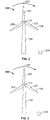
- FIG. 2 shows a wind turbine 100 having a first blade 201, a second blade 203, and a third blade 205 rotatable in direction 207.
- a noise measuring device 209 is arranged at a location disposed to measure noise from individual blades.
- the noise measuring device 209 may be any device capable of measuring noise or sound pressure level, including, but not limited to a microphone, acoustical camera, laser doppler vibrometer or other sound measuring or detection device, including devices that directly measure sound pressure level or indirectly via contact-less measurements.
- the noise-measuring device 209 is positioned in a location suitable for measuring the noise generated from a single blade 108, while noise generated by the other blades in minimized to reduce interference with the noise measurements of the individual blades.
- the noise-sensing device may be disposed below the down stroke of the blades 108.
- the positioning is not so limited and may include any location in which the magnitude of the noise generated by one blade is distinguishable from the noise generated by the other blades 108.
- FIG. 2 includes first blade 201 in a 12 o'clock or zero degree position (i.e., a vertical position above the hub 110).
- a rotational trigger is activated by the position of first blade 201.
- the time required for the first blade 201 to rotate and return to the zero degree position is measured by measuring the time between signals from the rotational trigger.
- the time is correlated to a rotational position (i.e., degrees from 0° to 360°) so that the measured sound power level may be further correlated to the blade 108 position.
- the rotational trigger may be any device that permits the recording of a position of one or more blades 108.
- the rotational trigger may be activated at a single position during a single rotation of the blades 108 or may be at several or continuously along the rotation of the blades 108.
- the rotational trigger is a mechanical feature, such as a protrusion, indentation, feature or lug on the shaft about which the hub 110 and blades 108 rotate. As the mechanical feature passes a predetermined point during rotation, a signal is produced and time is recorded.
- the rotational trigger is an electrical switch that sends a signal when the shaft rotates past a predetermined location.
- the time between activation of the rotational trigger is also measured.
- noise level is measured with a noise measuring device 209.
- the rotational position of the first blade 201 is determined by correlating a rotational position over time between signals from the rotational trigger.
- correlating it is meant that the time for a single rotation is measured and compared or plotted against the noise level magnitudes for this same period of time.
- Correlating the noise level measured by the noise measuring device includes normalizing the time between two trigger signals to 0° to 360° degree (rounded) to reduce or eliminate the dependency of rotor speed. Such correlation permits the identification and magnitude of the noise levels for the particular blades 108 (see e.g., FIG. 5 ).
- the first blade 201 or reference blade is in the zero degree position, wherein the rotational trigger is activated.
- the time required for the first blade 201 to rotate and return to the zero degree position is measured by measuring the time between signals from the rotational trigger.
- FIG. 3 shows the first blade 201 in a rotated position, wherein the first blade 201 has rotated in a direction 207 toward the noise-measuring device 209.
- a noise level at or near a maximum noise level may be measured at noise measuring device 209 when first blade 201 is in the position shown in FIG. 4 .
- the noise measuring device 209 obtains continuous measurements of levels of noise detected from the blades 108 of the wind turbine 100.
- FIG. 5 several maximums in noise level may occur, the maximums being associated with each of the blades 108.
- FIG. 5 shows an example of the noise level measured at the noise-measuring device 209 during the rotation of the blades 108.
- the graph illustrates noise level in decibels, but any other sound pressure level units may be utilized.
- the noise level is shown with respect to position in radial degrees.
- the rotational trigger is activated and signal corresponding to the position of the first blade 201 is recorded. While, the rotational trigger is illustrated as a signal corresponding to the zero degree position, the rotational trigger may be activated at any suitable position or at multiple positions.
- the position of the first blade 201 is determined by measuring noise level at the noise-measuring device 209 continuously over time until the rotational trigger is activated again, marking the completion of the rotation of the first blade 201.
- the rotational positioning over time is correlated to the noise level measured at the noise-measuring device 209 and the magnitudes are shown in FIG. 5 over an entire single rotation.
- the data for the single rotations may be stored for later analysis or may be utilized to aggregate data for multiple rotations. As can be seen in FIG. 5 , peaks appear in the noise levels between the activation of the trigger.
- the second blade 203 is in a position wherein the noise level produced by the second blade 203 is near a maximum (e.g., about 120° of rotation). This is shown as the first peak 501.
- second peak 503 corresponds to the first blade 201 and the third peak 505 corresponds to the third blade 205.
- FIG. 6 illustrates a method for configuring a wind turbine 100 for a desired noise level according to an embodiment of the present disclosure.
- the method includes measuring sound pressure level or noise level with noise measuring device 209 during wind turbine 100 operation.
- a wind turbine 100 is configured with blades 108 having few or no aerodynamic modification devices (i.e., bare blades), step 601.
- Noise level is measured as a function of power, rpm and/or pitch of the blades 108, step 603.
- the noise level of the individual blades 108 is measured by recording the rotational position using time between activation of the rotational trigger with respect to the noise level measured at the noise measuring device 209 and observing the absolute peaks of the noise level measured.
- the noise level is then averaged using suitable averaging calculations against stable operating conditions to determine the absolute noise level and optimum noise levels for the individual blades, step 605.
- the data obtained is compared for each blade with respect to each other, step 607.
- the data is analyzed to determine the stability of the data and to determine whether the stability is sufficient to determine the absolute noise level desired by the individual blades 108, step 609.
- stable data may include a predetermined minimum number of data values per blade and wind bin, distributed over a turbine operational range. For example, each wind bin (e.g., 5.5 to 6.5 m/s) may be filled with at leased 36 valid and undisturbed data points.
- steps 603-609 the process is repeated with measuring the noise of the individual blades 108 at step 603. If sufficient stable data exists, then a blade 108 is selected as a reference blade, step 611. While not so limited, the reference blade may be selected as the blade having the least value for noise level.
- At least one of the blades 108 are removed from the wind turbine and outfitted with noise reduction devices, step 613.
- Noise reduction devices may include, but are not limited to aerodynamic modification devices. Aerodynamic modification devices may be arranged and disposed on the blades 108. In other embodiments, blades 108 configured with differing aerodynamic profiles (e.g., varied airfoil geometries) may also be substituted for the blades 108 to determine the noise generated.
- the aerodynamic modification devices may include, but are not limited to turbulator holes, zig-zag (ZZ) turbulator tape, stall strips, vortex generators, Gurney flaps, acoustical flaps, any combinations thereof, or any other device or configuration capable of manipulating the aeorodynamic flow over the blade 108.
- the arrangement of noise reduction devices selected may be based on any criteria. For example, the arrangement may be a random arrangement, a preselected arrangement or an arrangement in response to historical data of configurations for a particular wind turbine or environment. Noise level is measured as a function of power, rpm and/or pitch of the blades 108, step 615.
- the noise level is then averaged against stable operating conditions to determine the absolute noise level and optimum noise levels for the individual blades, step 615.
- the data is analyzed to determine the stability of the data and to determine whether the stability is sufficient to determine the absolute noise level desired by the individual blades 108, step 615.
- the desired noise levels may be a minimum amount of noise, may be a noise level established by local ordinance or statute, or may be an optimal noise level with respect to cost or turbine efficiency.
- the blades 108 are provided with the configuration associated with the desired noise level and the wind turbine is permitted to operate, step 621.
- the present method of measuring noise level permits the analyzing of many different wind turbine parameters, including, but not limited to wind speed, turbine output, rpm, pitch of the blades 108 or a variety of other wind turbine parameters.
- FIG. 7 shows noise levels with upwind measurements (LUV) over a period of time with respect to wind speed.
- LUV upwind measurements
- the optimum or desired configuration of blade 108 may be obtained with respect to a variety of wind speeds. Additional data manipulation may also be provided, wherein comparisons with respect to any of the wind turbine parameters may be accomplished in order to determine the desired or optimum configuration for noise levels generated by the wind turbine 100.
Landscapes
- Engineering & Computer Science (AREA)
- Life Sciences & Earth Sciences (AREA)
- Sustainable Development (AREA)
- Sustainable Energy (AREA)
- Chemical & Material Sciences (AREA)
- Combustion & Propulsion (AREA)
- Mechanical Engineering (AREA)
- General Engineering & Computer Science (AREA)
- Physics & Mathematics (AREA)
- Fluid Mechanics (AREA)
- Wind Motors (AREA)
Claims (8)
- Verfahren zum Konfigurieren von Blättern (108) einer Windturbine (100) für geringe Geräuscherzeugung, umfassend:Bereitstellen von zumindest einer Geräuschmessvorrichtung (209);Anordnen und Disponieren der Geräuschmessvorrichtung (209) in einer Position, um ein Geräusch der Blätter (108) während der Drehung zu messen;Konfigurieren der Windturbine (100), um einen Drehtrigger aufzuweisen, wobei der Drehtrigger angeordnet ist, um ein Signal an einer vorbestimmten Drehposition der Windturbinenblätter (108) bereitzustellen;Konfigurieren eines oder mehrerer der Blätter (108) mit einer aerodynamischen Modifizierungsvorrichtung;Messen eines Geräuschpegels mit der Geräuschmessvorrichtung (209) während des Betriebs der Windturbine (100);gekennzeichnet, durch:individuelles Bestimmen des Geräusches, das durch jedes der Blätter (108) erzeugt wird; undKonfigurieren der Blätter (108) als Reaktion auf das für jedes der Blätter (108) individuell bestimmte Geräusch.
- Verfahren nach Anspruch 1, wobei die Geräuschmessvorrichtung (209) ein Mikrofon ist.
- Verfahren nach einem der vorstehenden Ansprüche, wobei der Drehtrigger ein mechanisches Merkmal an einer Welle ist, um die sich die Blätter (108) drehen.
- Verfahren nach einem vorstehenden der Ansprüche, wobei der Drehtrigger konfiguriert ist, um an einer vorausgewählten Blattposition aktiviert zu werden.
- Verfahren nach einem vorstehenden der Ansprüche, wobei der Drehtrigger ein elektronischer Schalter ist, der angeordnet ist, um an einer vorausgewählten Blattposition aktiviert zu werden.
- Verfahren nach einem vorstehenden der Ansprüche, wobei die aerodynamische Modifizierungsvorrichtung ausgewählt ist, aus der Gruppe, bestehend aus Turbulatorlöchern, Zickzack (ZZ)-Turbulatorband, Strömungsabrissstreifen, Wirbelgeneratoren, Gurney-Klappen, akustischen Klappen und Kombinationen davon.
- Verfahren nach einem vorstehenden der Ansprüche, weiter umfassend ein Konfigurieren der Blätter (108) ohne aerodynamische Modifizierungsvorrichtungen und Messen eines Geräuschpegels mit der Geräuschmessvorrichtung (209) vor dem Konfigurieren des einen oder der mehreren der Blätter (108) mit einer aerodynamischen Modifizierungsvorrichtung.
- Verfahren nach einem der vorstehenden Ansprüche, weiter umfassend ein Vergleichen des Geräuschpegels der Blätter (108) mit einer aerodynamischen Modifizierungsvorrichtung mit einem Blatt (108), das keine aerodynamische Modifizierungsvorrichtung aufweist.
Applications Claiming Priority (1)
| Application Number | Priority Date | Filing Date | Title |
|---|---|---|---|
| US11/967,410 US8197207B2 (en) | 2007-12-31 | 2007-12-31 | Individual blade noise measurement system and method for wind turbines |
Publications (3)
| Publication Number | Publication Date |
|---|---|
| EP2075465A2 EP2075465A2 (de) | 2009-07-01 |
| EP2075465A3 EP2075465A3 (de) | 2012-08-15 |
| EP2075465B1 true EP2075465B1 (de) | 2018-06-20 |
Family
ID=40283433
Family Applications (1)
| Application Number | Title | Priority Date | Filing Date |
|---|---|---|---|
| EP08171653.2A Active EP2075465B1 (de) | 2007-12-31 | 2008-12-15 | Vorrichtung und Verfahren zur individuellen Messung des Schalls bei Blättern einer Windenergieanlage |
Country Status (4)
| Country | Link |
|---|---|
| US (1) | US8197207B2 (de) |
| EP (1) | EP2075465B1 (de) |
| CN (1) | CN101476538B (de) |
| DK (1) | DK2075465T3 (de) |
Families Citing this family (10)
| Publication number | Priority date | Publication date | Assignee | Title |
|---|---|---|---|---|
| DE102008026842B3 (de) * | 2008-06-05 | 2010-02-18 | Repower Systems Ag | Verfahren und Anordnung zum Überwachen des Betriebs einer Windenergieanlage |
| AU2008362683A1 (en) * | 2008-10-09 | 2010-04-15 | Mitsubishi Heavy Industries, Ltd. | Offshore wind-driven electric power generator and offshore wind farm |
| US9651026B2 (en) * | 2010-09-23 | 2017-05-16 | Institut Fur Rundfunktechnik Gmbh | Wind turbine with electromagnetic wave transmission system |
| US8505384B2 (en) * | 2011-02-08 | 2013-08-13 | United Technologies Corporation | Rig for measuring bladed component mistuning |
| US20130003071A1 (en) * | 2011-06-30 | 2013-01-03 | Catch the Wind, Inc. | System and Method of In Situ Wind Turbine Blade Monitoring |
| CN103797244B (zh) * | 2011-08-16 | 2017-09-12 | 维斯塔斯风力系统集团公司 | 用于风力涡轮机的声噪声监测系统 |
| DE102011057175A1 (de) * | 2011-12-30 | 2013-07-04 | Prüftechnik Dieter Busch AG | Verfahren zur Schwingungsmessung an Rotorblättern von Windenergieanlagen |
| DK2626550T3 (en) * | 2012-02-10 | 2016-08-15 | Siemens Ag | Improved noise reduction control for wind turbines |
| US9528493B2 (en) * | 2013-05-28 | 2016-12-27 | Siemens Aktiengesellschaft | Apparatus to detect aerodynamic conditions of blades of wind turbines |
| CN113790129B (zh) * | 2021-09-08 | 2022-11-08 | 中国华能集团清洁能源技术研究院有限公司 | 一种风机叶片声音信号采集最优位置选取方法 |
Citations (2)
| Publication number | Priority date | Publication date | Assignee | Title |
|---|---|---|---|---|
| JP2004293527A (ja) | 2003-03-28 | 2004-10-21 | Ebara Corp | 風車装置、および風力発電装置 |
| WO2006122547A1 (en) | 2005-05-17 | 2006-11-23 | Vestas Wind Systems A/S | A pitch controlled wind turbine blade, a wind turbine and use hereof |
Family Cites Families (9)
| Publication number | Priority date | Publication date | Assignee | Title |
|---|---|---|---|---|
| US5471880A (en) * | 1994-04-28 | 1995-12-05 | Electric Power Research Institute | Method and apparatus for isolating and identifying periodic Doppler signals in a turbine |
| JP2001020848A (ja) * | 1999-07-02 | 2001-01-23 | Mitsubishi Heavy Ind Ltd | 翼発生音計測装置 |
| DE10032314C1 (de) * | 2000-07-04 | 2001-12-13 | Aloys Wobben | Verfahren zur Bestimmung des Winkels eines Rotorblatts einer Windenergieanlage |
| US7059833B2 (en) * | 2001-11-26 | 2006-06-13 | Bonus Energy A/S | Method for improvement of the efficiency of a wind turbine rotor |
| JP2003254226A (ja) * | 2002-03-05 | 2003-09-10 | Ebara Corp | 風車の気流騒音低減装置 |
| DE102005017054B4 (de) * | 2004-07-28 | 2012-01-05 | Igus - Innovative Technische Systeme Gmbh | Verfahren und Vorrichtung zur Überwachung des Zustandes von Rotorblättern an Windkraftanlagen |
| US7476985B2 (en) * | 2005-07-22 | 2009-01-13 | Gamesa Innovation & Technology, S.L. | Method of operating a wind turbine |
| JP2007204017A (ja) * | 2006-02-06 | 2007-08-16 | Fuji Heavy Ind Ltd | 衝撃吸収部材およびそれを用いた車両用バンパ構造 |
| DE102008026842B3 (de) * | 2008-06-05 | 2010-02-18 | Repower Systems Ag | Verfahren und Anordnung zum Überwachen des Betriebs einer Windenergieanlage |
-
2007
- 2007-12-31 US US11/967,410 patent/US8197207B2/en active Active
-
2008
- 2008-12-15 EP EP08171653.2A patent/EP2075465B1/de active Active
- 2008-12-15 DK DK08171653.2T patent/DK2075465T3/en active
- 2008-12-30 CN CN200810189748.5A patent/CN101476538B/zh active Active
Patent Citations (2)
| Publication number | Priority date | Publication date | Assignee | Title |
|---|---|---|---|---|
| JP2004293527A (ja) | 2003-03-28 | 2004-10-21 | Ebara Corp | 風車装置、および風力発電装置 |
| WO2006122547A1 (en) | 2005-05-17 | 2006-11-23 | Vestas Wind Systems A/S | A pitch controlled wind turbine blade, a wind turbine and use hereof |
Also Published As
| Publication number | Publication date |
|---|---|
| EP2075465A2 (de) | 2009-07-01 |
| EP2075465A3 (de) | 2012-08-15 |
| US8197207B2 (en) | 2012-06-12 |
| CN101476538A (zh) | 2009-07-08 |
| CN101476538B (zh) | 2016-02-03 |
| DK2075465T3 (en) | 2018-07-30 |
| US20100284787A1 (en) | 2010-11-11 |
Similar Documents
| Publication | Publication Date | Title |
|---|---|---|
| US8197207B2 (en) | Individual blade noise measurement system and method for wind turbines | |
| DK2258942T3 (en) | System and method for wind noise control and skadedetektering | |
| DK177922B1 (en) | Method and system for monitoring wind turbine | |
| EP2026160B1 (de) | Überwachung mittels Signalkombination | |
| US8210811B2 (en) | Apparatus and method for operation of a wind turbine | |
| EP3043062B1 (de) | Zustandsüberwachungsvorrichtung für eine vorrichtung zur windenergieerzeugung | |
| EP2295793B1 (de) | System für die Bestimmung einer Ausschaltsgrenze für eine Windturbine | |
| US8169098B2 (en) | Wind turbine and operating same | |
| EP1959130B1 (de) | Verfahren zur Optimierung eines Windturbinenbetriebs | |
| EP1748185B1 (de) | Feststellung von Vereisung für eine Windturbine | |
| EP2543876B1 (de) | Steuerung der Amplituden-Modulation von Lärm von Windkraftanlagen | |
| WO2015077337A1 (en) | System and method for assessing the performance impact of wind turbine upgrades | |
| AU2014200423A1 (en) | Method and apparatus for wind turbine noise reduction | |
| EP2295794A2 (de) | Windturbine als Windrichtungssensor | |
| EP2610604B1 (de) | Verfahren zur Schwingungsmessung auf Rotorschaufeln von Windkraftwerken | |
| EP3237753B1 (de) | Verfahren für den betrieb einer windturbine | |
| Botta et al. | Effects of hostile terrains on wind turbine performances and loads: The Acqua Spruzza experience | |
| EP3677772B1 (de) | Verfahren zum betreiben einer windturbine basierend auf der maximalen schubgrenze | |
| US12012927B2 (en) | System and method for detecting a failure condition in a component of a wind turbine | |
| WO2026043489A1 (en) | System and method for yawing a wind turbine within a constrained yaw angle sweep upon detection of blade vibrations | |
| DK3237753T3 (en) | A WAY TO OPERATE A WINDMILL | |
| WO2026043488A1 (en) | System and method for yawing a wind turbine based on avoiding critical blade angles of attack when yaw angle sweep is constrained | |
| CN121024862A (zh) | 风电机组偏航系统故障判断方法、装置、设备及存储介质 |
Legal Events
| Date | Code | Title | Description |
|---|---|---|---|
| PUAI | Public reference made under article 153(3) epc to a published international application that has entered the european phase |
Free format text: ORIGINAL CODE: 0009012 |
|
| AK | Designated contracting states |
Kind code of ref document: A2 Designated state(s): AT BE BG CH CY CZ DE DK EE ES FI FR GB GR HR HU IE IS IT LI LT LU LV MC MT NL NO PL PT RO SE SI SK TR |
|
| AX | Request for extension of the european patent |
Extension state: AL BA MK RS |
|
| RIN1 | Information on inventor provided before grant (corrected) |
Inventor name: WITTEKIND, LOTHAR Inventor name: PETERSEN, ANDREAS Inventor name: KRAFT, HEIKO |
|
| PUAL | Search report despatched |
Free format text: ORIGINAL CODE: 0009013 |
|
| AK | Designated contracting states |
Kind code of ref document: A3 Designated state(s): AT BE BG CH CY CZ DE DK EE ES FI FR GB GR HR HU IE IS IT LI LT LU LV MC MT NL NO PL PT RO SE SI SK TR |
|
| AX | Request for extension of the european patent |
Extension state: AL BA MK RS |
|
| RIC1 | Information provided on ipc code assigned before grant |
Ipc: F03D 11/00 20060101AFI20120706BHEP Ipc: F03D 7/02 20060101ALI20120706BHEP |
|
| 17P | Request for examination filed |
Effective date: 20130215 |
|
| AKX | Designation fees paid |
Designated state(s): DE DK ES |
|
| 17Q | First examination report despatched |
Effective date: 20160720 |
|
| STAA | Information on the status of an ep patent application or granted ep patent |
Free format text: STATUS: EXAMINATION IS IN PROGRESS |
|
| REG | Reference to a national code |
Ref country code: DE Ref legal event code: R079 Ref document number: 602008055675 Country of ref document: DE Free format text: PREVIOUS MAIN CLASS: F03D0011000000 Ipc: F03D0080000000 |
|
| RIC1 | Information provided on ipc code assigned before grant |
Ipc: F03D 80/00 20160101AFI20180212BHEP |
|
| GRAP | Despatch of communication of intention to grant a patent |
Free format text: ORIGINAL CODE: EPIDOSNIGR1 |
|
| STAA | Information on the status of an ep patent application or granted ep patent |
Free format text: STATUS: GRANT OF PATENT IS INTENDED |
|
| INTG | Intention to grant announced |
Effective date: 20180328 |
|
| GRAS | Grant fee paid |
Free format text: ORIGINAL CODE: EPIDOSNIGR3 |
|
| GRAA | (expected) grant |
Free format text: ORIGINAL CODE: 0009210 |
|
| STAA | Information on the status of an ep patent application or granted ep patent |
Free format text: STATUS: THE PATENT HAS BEEN GRANTED |
|
| AK | Designated contracting states |
Kind code of ref document: B1 Designated state(s): DE DK ES |
|
| REG | Reference to a national code |
Ref country code: DE Ref legal event code: R096 Ref document number: 602008055675 Country of ref document: DE |
|
| REG | Reference to a national code |
Ref country code: DK Ref legal event code: T3 Effective date: 20180719 |
|
| PG25 | Lapsed in a contracting state [announced via postgrant information from national office to epo] |
Ref country code: ES Free format text: LAPSE BECAUSE OF FAILURE TO SUBMIT A TRANSLATION OF THE DESCRIPTION OR TO PAY THE FEE WITHIN THE PRESCRIBED TIME-LIMIT Effective date: 20180620 |
|
| REG | Reference to a national code |
Ref country code: DE Ref legal event code: R026 Ref document number: 602008055675 Country of ref document: DE |
|
| PLBI | Opposition filed |
Free format text: ORIGINAL CODE: 0009260 |
|
| PLAX | Notice of opposition and request to file observation + time limit sent |
Free format text: ORIGINAL CODE: EPIDOSNOBS2 |
|
| 26 | Opposition filed |
Opponent name: SIEMENS GAMESA RENEWABLE ENERGY GMBH & CO. KG Effective date: 20190320 |
|
| PLBB | Reply of patent proprietor to notice(s) of opposition received |
Free format text: ORIGINAL CODE: EPIDOSNOBS3 |
|
| REG | Reference to a national code |
Ref country code: DE Ref legal event code: R100 Ref document number: 602008055675 Country of ref document: DE |
|
| PLCK | Communication despatched that opposition was rejected |
Free format text: ORIGINAL CODE: EPIDOSNREJ1 |
|
| PLBN | Opposition rejected |
Free format text: ORIGINAL CODE: 0009273 |
|
| STAA | Information on the status of an ep patent application or granted ep patent |
Free format text: STATUS: OPPOSITION REJECTED |
|
| 27O | Opposition rejected |
Effective date: 20211006 |
|
| P01 | Opt-out of the competence of the unified patent court (upc) registered |
Effective date: 20230530 |
|
| REG | Reference to a national code |
Ref country code: DE Ref legal event code: R081 Ref document number: 602008055675 Country of ref document: DE Owner name: GENERAL ELECTRIC RENOVABLES ESPANA, S.L., ES Free format text: FORMER OWNER: GENERAL ELECTRIC COMPANY, SCHENECTADY, NY, US |
|
| PGFP | Annual fee paid to national office [announced via postgrant information from national office to epo] |
Ref country code: DE Payment date: 20251126 Year of fee payment: 18 |
|
| PGFP | Annual fee paid to national office [announced via postgrant information from national office to epo] |
Ref country code: DK Payment date: 20251119 Year of fee payment: 18 |