EP2075463A2 - Wind power installation and method of operating it - Google Patents
Wind power installation and method of operating it Download PDFInfo
- Publication number
- EP2075463A2 EP2075463A2 EP08021990A EP08021990A EP2075463A2 EP 2075463 A2 EP2075463 A2 EP 2075463A2 EP 08021990 A EP08021990 A EP 08021990A EP 08021990 A EP08021990 A EP 08021990A EP 2075463 A2 EP2075463 A2 EP 2075463A2
- Authority
- EP
- European Patent Office
- Prior art keywords
- network
- frequency
- threshold value
- network frequency
- controller
- Prior art date
- Legal status (The legal status is an assumption and is not a legal conclusion. Google has not performed a legal analysis and makes no representation as to the accuracy of the status listed.)
- Granted
Links
- 238000009434 installation Methods 0.000 title claims abstract description 72
- 238000000034 method Methods 0.000 title claims abstract description 41
- 238000002347 injection Methods 0.000 claims description 43
- 239000007924 injection Substances 0.000 claims description 43
- 230000007423 decrease Effects 0.000 claims description 14
- 230000003247 decreasing effect Effects 0.000 claims description 13
- 230000010354 integration Effects 0.000 claims description 2
- 230000008030 elimination Effects 0.000 abstract 1
- 238000003379 elimination reaction Methods 0.000 abstract 1
- 238000010586 diagram Methods 0.000 description 8
- 230000006870 function Effects 0.000 description 8
- 230000009467 reduction Effects 0.000 description 8
- 230000010355 oscillation Effects 0.000 description 7
- 230000033228 biological regulation Effects 0.000 description 5
- 230000000694 effects Effects 0.000 description 5
- 230000008859 change Effects 0.000 description 4
- 230000008569 process Effects 0.000 description 4
- 230000004044 response Effects 0.000 description 3
- 230000009471 action Effects 0.000 description 2
- 230000008901 benefit Effects 0.000 description 2
- 238000010248 power generation Methods 0.000 description 2
- 238000009987 spinning Methods 0.000 description 2
- 230000006641 stabilisation Effects 0.000 description 2
- LUNBMBVWKORSGN-TYEKWLQESA-N P-factor Chemical compound CC(C)C[C@@H](C(O)=O)NC(=O)[C@H](CC(N)=O)NC(=O)[C@@H]1CCCN1C(=O)[C@H](CCCNC(N)=N)NC(=O)[C@H](CC(O)=O)NC(=O)[C@H]1N(C(=O)[C@H](CC(N)=O)NC(=O)[C@@H](NC(=O)[C@H](CC=2C=CC=CC=2)NC(=O)[C@@H](NC(=O)[C@H](CC(N)=O)NC(=O)[C@H](CC=2C3=CC=CC=C3NC=2)NC(=O)[C@H](CO)NC(=O)[C@H](CCC(N)=O)NC(=O)[C@H](CC=2C=CC(O)=CC=2)NC(=O)[C@H](C)NC(=O)[C@H](CCCNC(N)=N)NC(=O)[C@H](CC(C)C)NC(=O)[C@H](CC=2C=CC=CC=2)NC(=O)[C@H](CC(O)=O)NC(=O)[C@H](C)NC(=O)[C@H](CC=2C=CC(O)=CC=2)NC(=O)[C@@H](N)[C@@H](C)O)[C@@H](C)O)C(C)C)CCC1 LUNBMBVWKORSGN-TYEKWLQESA-N 0.000 description 1
- 101800002502 P-factor Proteins 0.000 description 1
- 230000000295 complement effect Effects 0.000 description 1
- 238000009795 derivation Methods 0.000 description 1
- -1 dimensions Substances 0.000 description 1
- 230000008713 feedback mechanism Effects 0.000 description 1
- 239000000463 material Substances 0.000 description 1
- 230000004043 responsiveness Effects 0.000 description 1
- 238000011105 stabilization Methods 0.000 description 1
Images


Classifications
-
- F—MECHANICAL ENGINEERING; LIGHTING; HEATING; WEAPONS; BLASTING
- F03—MACHINES OR ENGINES FOR LIQUIDS; WIND, SPRING, OR WEIGHT MOTORS; PRODUCING MECHANICAL POWER OR A REACTIVE PROPULSIVE THRUST, NOT OTHERWISE PROVIDED FOR
- F03D—WIND MOTORS
- F03D7/00—Controlling wind motors
- F03D7/02—Controlling wind motors the wind motors having rotation axis substantially parallel to the air flow entering the rotor
- F03D7/028—Controlling wind motors the wind motors having rotation axis substantially parallel to the air flow entering the rotor controlling wind motor output power
- F03D7/0284—Controlling wind motors the wind motors having rotation axis substantially parallel to the air flow entering the rotor controlling wind motor output power in relation to the state of the electric grid
-
- F—MECHANICAL ENGINEERING; LIGHTING; HEATING; WEAPONS; BLASTING
- F03—MACHINES OR ENGINES FOR LIQUIDS; WIND, SPRING, OR WEIGHT MOTORS; PRODUCING MECHANICAL POWER OR A REACTIVE PROPULSIVE THRUST, NOT OTHERWISE PROVIDED FOR
- F03D—WIND MOTORS
- F03D7/00—Controlling wind motors
- F03D7/02—Controlling wind motors the wind motors having rotation axis substantially parallel to the air flow entering the rotor
- F03D7/04—Automatic control; Regulation
- F03D7/042—Automatic control; Regulation by means of an electrical or electronic controller
- F03D7/043—Automatic control; Regulation by means of an electrical or electronic controller characterised by the type of control logic
- F03D7/044—Automatic control; Regulation by means of an electrical or electronic controller characterised by the type of control logic with PID control
-
- F—MECHANICAL ENGINEERING; LIGHTING; HEATING; WEAPONS; BLASTING
- F03—MACHINES OR ENGINES FOR LIQUIDS; WIND, SPRING, OR WEIGHT MOTORS; PRODUCING MECHANICAL POWER OR A REACTIVE PROPULSIVE THRUST, NOT OTHERWISE PROVIDED FOR
- F03D—WIND MOTORS
- F03D9/00—Adaptations of wind motors for special use; Combinations of wind motors with apparatus driven thereby; Wind motors specially adapted for installation in particular locations
- F03D9/20—Wind motors characterised by the driven apparatus
- F03D9/25—Wind motors characterised by the driven apparatus the apparatus being an electrical generator
- F03D9/255—Wind motors characterised by the driven apparatus the apparatus being an electrical generator connected to electrical distribution networks; Arrangements therefor
-
- H—ELECTRICITY
- H02—GENERATION; CONVERSION OR DISTRIBUTION OF ELECTRIC POWER
- H02J—CIRCUIT ARRANGEMENTS OR SYSTEMS FOR SUPPLYING OR DISTRIBUTING ELECTRIC POWER; SYSTEMS FOR STORING ELECTRIC ENERGY
- H02J3/00—Circuit arrangements for ac mains or ac distribution networks
- H02J3/38—Arrangements for parallely feeding a single network by two or more generators, converters or transformers
- H02J3/381—Dispersed generators
-
- H—ELECTRICITY
- H02—GENERATION; CONVERSION OR DISTRIBUTION OF ELECTRIC POWER
- H02J—CIRCUIT ARRANGEMENTS OR SYSTEMS FOR SUPPLYING OR DISTRIBUTING ELECTRIC POWER; SYSTEMS FOR STORING ELECTRIC ENERGY
- H02J3/00—Circuit arrangements for ac mains or ac distribution networks
- H02J3/38—Arrangements for parallely feeding a single network by two or more generators, converters or transformers
- H02J3/46—Controlling of the sharing of output between the generators, converters, or transformers
- H02J3/466—Scheduling the operation of the generators, e.g. connecting or disconnecting generators to meet a given demand
- H02J3/472—For selectively connecting the AC sources in a particular order, e.g. sequential, alternating or subsets of sources
-
- H—ELECTRICITY
- H02—GENERATION; CONVERSION OR DISTRIBUTION OF ELECTRIC POWER
- H02J—CIRCUIT ARRANGEMENTS OR SYSTEMS FOR SUPPLYING OR DISTRIBUTING ELECTRIC POWER; SYSTEMS FOR STORING ELECTRIC ENERGY
- H02J3/00—Circuit arrangements for ac mains or ac distribution networks
- H02J3/38—Arrangements for parallely feeding a single network by two or more generators, converters or transformers
- H02J3/46—Controlling of the sharing of output between the generators, converters, or transformers
- H02J3/48—Controlling the sharing of the in-phase component
-
- H—ELECTRICITY
- H02—GENERATION; CONVERSION OR DISTRIBUTION OF ELECTRIC POWER
- H02P—CONTROL OR REGULATION OF ELECTRIC MOTORS, ELECTRIC GENERATORS OR DYNAMO-ELECTRIC CONVERTERS; CONTROLLING TRANSFORMERS, REACTORS OR CHOKE COILS
- H02P9/00—Arrangements for controlling electric generators for the purpose of obtaining a desired output
- H02P9/42—Arrangements for controlling electric generators for the purpose of obtaining a desired output to obtain desired frequency without varying speed of the generator
-
- F—MECHANICAL ENGINEERING; LIGHTING; HEATING; WEAPONS; BLASTING
- F05—INDEXING SCHEMES RELATING TO ENGINES OR PUMPS IN VARIOUS SUBCLASSES OF CLASSES F01-F04
- F05B—INDEXING SCHEME RELATING TO WIND, SPRING, WEIGHT, INERTIA OR LIKE MOTORS, TO MACHINES OR ENGINES FOR LIQUIDS COVERED BY SUBCLASSES F03B, F03D AND F03G
- F05B2220/00—Application
- F05B2220/70—Application in combination with
- F05B2220/702—Application in combination with the other apparatus being a steam turbine
-
- F—MECHANICAL ENGINEERING; LIGHTING; HEATING; WEAPONS; BLASTING
- F05—INDEXING SCHEMES RELATING TO ENGINES OR PUMPS IN VARIOUS SUBCLASSES OF CLASSES F01-F04
- F05B—INDEXING SCHEME RELATING TO WIND, SPRING, WEIGHT, INERTIA OR LIKE MOTORS, TO MACHINES OR ENGINES FOR LIQUIDS COVERED BY SUBCLASSES F03B, F03D AND F03G
- F05B2220/00—Application
- F05B2220/70—Application in combination with
- F05B2220/704—Application in combination with the other apparatus being a gas turbine
-
- F—MECHANICAL ENGINEERING; LIGHTING; HEATING; WEAPONS; BLASTING
- F05—INDEXING SCHEMES RELATING TO ENGINES OR PUMPS IN VARIOUS SUBCLASSES OF CLASSES F01-F04
- F05B—INDEXING SCHEME RELATING TO WIND, SPRING, WEIGHT, INERTIA OR LIKE MOTORS, TO MACHINES OR ENGINES FOR LIQUIDS COVERED BY SUBCLASSES F03B, F03D AND F03G
- F05B2220/00—Application
- F05B2220/70—Application in combination with
- F05B2220/706—Application in combination with an electrical generator
-
- F—MECHANICAL ENGINEERING; LIGHTING; HEATING; WEAPONS; BLASTING
- F05—INDEXING SCHEMES RELATING TO ENGINES OR PUMPS IN VARIOUS SUBCLASSES OF CLASSES F01-F04
- F05B—INDEXING SCHEME RELATING TO WIND, SPRING, WEIGHT, INERTIA OR LIKE MOTORS, TO MACHINES OR ENGINES FOR LIQUIDS COVERED BY SUBCLASSES F03B, F03D AND F03G
- F05B2270/00—Control
- F05B2270/10—Purpose of the control system
- F05B2270/103—Purpose of the control system to affect the output of the engine
- F05B2270/1033—Power (if explicitly mentioned)
-
- F—MECHANICAL ENGINEERING; LIGHTING; HEATING; WEAPONS; BLASTING
- F05—INDEXING SCHEMES RELATING TO ENGINES OR PUMPS IN VARIOUS SUBCLASSES OF CLASSES F01-F04
- F05B—INDEXING SCHEME RELATING TO WIND, SPRING, WEIGHT, INERTIA OR LIKE MOTORS, TO MACHINES OR ENGINES FOR LIQUIDS COVERED BY SUBCLASSES F03B, F03D AND F03G
- F05B2270/00—Control
- F05B2270/10—Purpose of the control system
- F05B2270/104—Purpose of the control system to match engine to driven device
- F05B2270/1041—Purpose of the control system to match engine to driven device in particular the electrical frequency of driven generator
-
- F—MECHANICAL ENGINEERING; LIGHTING; HEATING; WEAPONS; BLASTING
- F05—INDEXING SCHEMES RELATING TO ENGINES OR PUMPS IN VARIOUS SUBCLASSES OF CLASSES F01-F04
- F05B—INDEXING SCHEME RELATING TO WIND, SPRING, WEIGHT, INERTIA OR LIKE MOTORS, TO MACHINES OR ENGINES FOR LIQUIDS COVERED BY SUBCLASSES F03B, F03D AND F03G
- F05B2270/00—Control
- F05B2270/30—Control parameters, e.g. input parameters
- F05B2270/309—Rate of change of parameters
-
- F—MECHANICAL ENGINEERING; LIGHTING; HEATING; WEAPONS; BLASTING
- F05—INDEXING SCHEMES RELATING TO ENGINES OR PUMPS IN VARIOUS SUBCLASSES OF CLASSES F01-F04
- F05B—INDEXING SCHEME RELATING TO WIND, SPRING, WEIGHT, INERTIA OR LIKE MOTORS, TO MACHINES OR ENGINES FOR LIQUIDS COVERED BY SUBCLASSES F03B, F03D AND F03G
- F05B2270/00—Control
- F05B2270/30—Control parameters, e.g. input parameters
- F05B2270/337—Electrical grid status parameters, e.g. voltage, frequency or power demand
-
- F—MECHANICAL ENGINEERING; LIGHTING; HEATING; WEAPONS; BLASTING
- F05—INDEXING SCHEMES RELATING TO ENGINES OR PUMPS IN VARIOUS SUBCLASSES OF CLASSES F01-F04
- F05B—INDEXING SCHEME RELATING TO WIND, SPRING, WEIGHT, INERTIA OR LIKE MOTORS, TO MACHINES OR ENGINES FOR LIQUIDS COVERED BY SUBCLASSES F03B, F03D AND F03G
- F05B2270/00—Control
- F05B2270/70—Type of control algorithm
- F05B2270/706—Type of control algorithm proportional-integral-differential
-
- H—ELECTRICITY
- H02—GENERATION; CONVERSION OR DISTRIBUTION OF ELECTRIC POWER
- H02J—CIRCUIT ARRANGEMENTS OR SYSTEMS FOR SUPPLYING OR DISTRIBUTING ELECTRIC POWER; SYSTEMS FOR STORING ELECTRIC ENERGY
- H02J2300/00—Systems for supplying or distributing electric power characterised by decentralized, dispersed, or local generation
- H02J2300/20—The dispersed energy generation being of renewable origin
- H02J2300/28—The renewable source being wind energy
-
- H—ELECTRICITY
- H02—GENERATION; CONVERSION OR DISTRIBUTION OF ELECTRIC POWER
- H02P—CONTROL OR REGULATION OF ELECTRIC MOTORS, ELECTRIC GENERATORS OR DYNAMO-ELECTRIC CONVERTERS; CONTROLLING TRANSFORMERS, REACTORS OR CHOKE COILS
- H02P2101/00—Special adaptation of control arrangements for generators
- H02P2101/15—Special adaptation of control arrangements for generators for wind-driven turbines
-
- Y—GENERAL TAGGING OF NEW TECHNOLOGICAL DEVELOPMENTS; GENERAL TAGGING OF CROSS-SECTIONAL TECHNOLOGIES SPANNING OVER SEVERAL SECTIONS OF THE IPC; TECHNICAL SUBJECTS COVERED BY FORMER USPC CROSS-REFERENCE ART COLLECTIONS [XRACs] AND DIGESTS
- Y02—TECHNOLOGIES OR APPLICATIONS FOR MITIGATION OR ADAPTATION AGAINST CLIMATE CHANGE
- Y02E—REDUCTION OF GREENHOUSE GAS [GHG] EMISSIONS, RELATED TO ENERGY GENERATION, TRANSMISSION OR DISTRIBUTION
- Y02E10/00—Energy generation through renewable energy sources
- Y02E10/70—Wind energy
- Y02E10/72—Wind turbines with rotation axis in wind direction
-
- Y—GENERAL TAGGING OF NEW TECHNOLOGICAL DEVELOPMENTS; GENERAL TAGGING OF CROSS-SECTIONAL TECHNOLOGIES SPANNING OVER SEVERAL SECTIONS OF THE IPC; TECHNICAL SUBJECTS COVERED BY FORMER USPC CROSS-REFERENCE ART COLLECTIONS [XRACs] AND DIGESTS
- Y02—TECHNOLOGIES OR APPLICATIONS FOR MITIGATION OR ADAPTATION AGAINST CLIMATE CHANGE
- Y02E—REDUCTION OF GREENHOUSE GAS [GHG] EMISSIONS, RELATED TO ENERGY GENERATION, TRANSMISSION OR DISTRIBUTION
- Y02E10/00—Energy generation through renewable energy sources
- Y02E10/70—Wind energy
- Y02E10/76—Power conversion electric or electronic aspects
Definitions
- the present invention relates to the field of wind energy systems and devices, and more specifically to the control of the way power generated by such systems and devices is supplied to a network or grid for distribution of the power.
- Wind energy systems and installations include one or more wind power generators or turbines arranged to produce electrical energy by rotation induced by the wind.
- This electrical energy generated by one or more of these generators (for example, by several generators forming part of or constituting a so-called "wind farm"), is supplied to a grid or network for distribution of the energy.
- a large number of electrical power generators are connected to the same grid, and normally several power consumers are also connected to the grid.
- regulation of the way in which wind power is injected and supplied to the grid has become increasingly important.
- a large number of patents, patent applications and other documents teach different ways of controlling the supply of wind power to the network.
- DE-A1-102005052011 (E.ON Netz GmbH), which describes how the active power injected into the grid from a wind power installation is varied according to a specified formula, related to the frequency on the network.
- a network is arranged to operate at a pre-established frequency, for example, in practice, 50 Hz or 60 Hz.
- the injection of power into the network should equal the consumption.
- the instantaneous or actual network frequency tends to sink.
- the actual network frequency tends to rise.
- the networks or grids, as well as the apparatus and installations connected to them for injection and/or consumption of active power are normally designed to tolerate minor deviations from the nominal frequency. However, substantial deviations can have negative effects on the operation of the network and on the devices connected to the network.
- DE-A1-10022974 (Aloys Wobben ) already proposed a reduction of the active power when the actual network frequency increased beyond a network frequency limit that was 0.3% above the nominal network frequency. Also, DE-A1-10022974 disclosed that no power should be injected into the network when the actual network frequency was 2% above the nominal network frequency. A controller was mentioned, but it was not disclosed exactly how it should operate.
- the regulation takes place only within a frequency range from 50.2 Hz and up to and including 51.5 Hz. Further, it is suggested that the wind power generator is to be automatically disconnected from the grid when the actual network frequency decreases below a lower frequency limit of 47.5 Hz and/or increases beyond an upper frequency limit of 51.5 Hz, whereby said disconnection should be a "physical" disconnection. It is stated that in this way, there is no risk that the generator remains connected to the network when the actual network frequency reaches values outside the above-mentioned range of 47.5 Hz-51.5 Hz.
- both DE-A1-102005052011 and DE-A1-10022974 mentioned above are based on some kind of "P” (proportional) regulation or also on some open loop control with a fixed P-gain which may, at least in some cases, help to reduce the contribution of a wind power installation to a further increase of the actual network frequency, but which may be insufficient to bring the actual network frequency back towards the nominal network frequency.
- P proportional
- a first aspect of the invention relates to a method of operating a wind power installation connected to a network for distribution of electrical power, said wind power installation comprising at least one wind power generator (that is, the wind power installation can correspond to a single wind power generator or wind turbine, or to a group of them, such as a wind farm or a part of a wind farm), said wind power installation being related to said network for injection of power into said network (that is, for injection of active power and, optionally, of reactive power, at one or more points of interconnection between the wind power installation and the network), said network having a nominal network frequency (f n ) (for example, 50 Hz) and said network being arranged for operating at said nominal network frequency (normally, within a band around said nominal network frequency).
- f n nominal network frequency
- the method comprises controlling the active power that is injected into said network from said wind power installation in view of a measured actual network frequency (f a ) at which the network is operating. More specifically, the method comprises the steps of
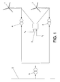
- Figure 1 schematically illustrates a wind power installation comprising a plurality of wind turbines or wind power generators 1, each one of them being connected, by a first transformer 4, to a second transformer 5 by means of which the wind turbines 1 are connected to a grid or network 2 for distribution of electrical power to a plurality of consumers (not illustrated) connected to the network. Conventionally, also other power producers (not illustrated) are connected to the network.
- a control system or controller 3 is provided (one controller can be used for the entire installation, or an individual controller can be provided for each wind turbine 1 or for a group of wind turbines).
- the controller 3 receives (for example, from an internal memory or from a remote control station) a reference value indicative of the nominal frequency (f n ) of the network 2, that is, of the frequency at which the network 2 should preferably operate. Typically, this frequency can be 50 Hz or 60 Hz.
- the controller receives a further input corresponding to a measured "actual frequency" (f a ) at which the network is actually operating.
- this actual frequency can deviate from the nominal frequency (for example, due to an excess of injected active power or due to insufficient injected active power).
- the controller 3 is designed to determine the difference E between the nominal frequency and the actual frequency (this can be done by a simple subtractor circuit 31), and to produce (by means of suitable hardware and software represented by the module 32) a power reference signal (P ref ) which determines the operation of the wind turbine(s) 1 (including its (their) converter system(s)) in a way so as to regulate the active power P A injected into the network 2 by the wind power installation, in the manner defined in the claims and described above (cf.also figure 3 ).
- P ref power reference signal
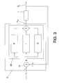
- the controller in accordance with one possible embodiment is illustrated with more detail in figure 3 .
- the hardware and software module 32 comprises a P (proportional) module, an I (integral) module and a D (derivative) module, thus embodying a PID controller.
- the gains corresponding to the P, I and D parts can be set by the skilled person (or be set in accordance with requirements of/agreements with the system operator) in view of the specific characteristics of the system.
- PID control as such is well known in the art, and the skilled person will be able to set the control parameters in an adequate manner. Thus, no further description of the details of the PID (or PD, or PI, or ID, or D, or I) control is considered necessary.
- the controller 32 produces the reference signal P ref which is taken as an input value for the control of the wind power installation 1, so as to adjust the active power P that is injected into the network accordingly.
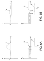
- Figures 6A and 6B schematically illustrate the importance or effect of a derivative (D) component of the controller 32 in order to help to prevent an excessive increase in the frequency error, for example, when there is a sudden drop in the power consumed from the network.
- D derivative
- Figure 6A includes a frequency diagram illustrating how the actual frequency (f a ) varies in time (t) (the upper diagram in figure 6A ), as a result of the variation of the power consumption (P C ) in the grid, the total amount of active power injected into the grid (P T ) from the different power suppliers connected to the grid, and the power injected from the controlled wind power installation (P W ) (the figures are merely schematic representations, and the "proportion" between the levels of the different curves do not correspond to any real situation), in the case of a wind power installation without a derivative control component.
- Figure 6B illustrates the same elements, but for a wind power installation with an appropriately set derivate (D) control component.
- figures 6A and 6B illustrate how a derivative control component can provide a very rapid and strong response to an increase in the frequency error, thus providing a suitable rapid and sufficient variation in the amount of injected power from the wind power installation (P w ), thereby reducing the maximum level of the frequency error (the maximum level of the frequency error is much lower in figure 6B than in figure 6A ).
- the control module 32 can additionally or alternatively be configured to implement hysteresis.
- the control module can be configured to control the active power P A that is injected into said network from said wind power installation in view of the measured actual network frequency (f a ) at which the network is operating, by
- control module can be configured to increase (instead of reducing) the amount of active power injected into the network, as a function of the actual network frequency (and as long as such an increase is possible in view of the output limitations of the wind power installation), if said actual network frequency decreases below a first lower network frequency threshold value (f 4 ), until, for example, said actual network frequency sinks below the second lower frequency threshold value (f 5 ).
- the injected active power can, for example, be kept constant, or be reduced, or be further increased, or even be set to zero, depending on grid codes or on the preferences of the operator of the network or the operator of the wind power installation.
- control module can be configured to stop injection of active power into the network if said actual network frequency decreases below said second lower network frequency threshold value (f 5 ) lower than said first lower frequency threshold value (f 4 ), and further be configured so that, once said actual network frequency has decreased below said second lower network frequency threshold value (f 5 ), injection of active power into the network is not resumed until the actual network frequency has increased beyond a third lower frequency threshold value (f 6 ) higher than said second lower frequency threshold value (f 5 ).
- Figure 5 illustrates two such possible embodiments of the invention.
- the power injected into the network from the wind power installation is at the maximum level P max when the actual network frequency corresponds to the nominal network frequency f n .
- P max the maximum level of the actual network frequency
- the actual network frequency increases beyond f 1
- power injection is reduced, and finally stopped when the frequency increases beyond f 2 , not to be resumed again until the frequency has decreased below f 3 , just as described in connection with figure 4 .
- the difference compared to the P 1 embodiment is that in accordance with the P 2 embodiment, the injected power is not decreased when the actual frequency sinks below f 4 ; instead, the maximum available active power is continued to be injected into the grid, until the actual frequency sinks below f 5 , in which case power injection is stopped, not to be resumed again until the frequency rises above f 6 .
- a further embodiment is illustrated by the power curve P 3 , similar to P 2 but with the difference that at network frequencies at f n and up until f 1 , the amount of active power injected into the network is not the maximum power that could be supplied by the wind power installation, but a lower amount of active power, reduced by an amount X which constitutes a so-called “power reserve” or "spinning reserve".
- This makes it possible to increase the amount of active power when the actual network frequency sinks below the first lower network frequency threshold value f 4 , until the maximum P max is reached, as shown in figure 5 (also here, injection can be stopped at f 5 and resumed at f 6 ). In this way, the arrangement helps to further stabilise the system, as the insufficient injection of active power that caused the decrease of the actual network frequency can be at least partly compensated by the "power reserve".
- FIGs 7A and 7B schematically illustrate two basic controller concepts that can be useful to implement different embodiments of the invention.
- a two-level hysteresis controller is illustrated, with a first input signal f ref (that could correspond to a "desired" value of, for example, a frequency, such as the nominal frequency f n referred to above) and a second input signal f m (which could be a measured "real" value of a frequency, such as the actual grid frequency f a referred to above), and an output signal which can have two different levels (for example, "0" or "1"), whereby the level of the output signal depends on the difference between the two input signals.
- f ref that could correspond to a "desired” value of, for example, a frequency, such as the nominal frequency f n referred to above
- f m which could be a measured "real" value of a frequency, such as the actual grid frequency f a referred to above
- an output signal which can have two
- Figure 7B illustrates a similar concept, but with an output signal that can have three different levels, such as "-1 ", "0” and "1".
Abstract
Description
- The present invention relates to the field of wind energy systems and devices, and more specifically to the control of the way power generated by such systems and devices is supplied to a network or grid for distribution of the power.
- Wind energy systems and installations include one or more wind power generators or turbines arranged to produce electrical energy by rotation induced by the wind. This electrical energy, generated by one or more of these generators (for example, by several generators forming part of or constituting a so-called "wind farm"), is supplied to a grid or network for distribution of the energy. Normally, a large number of electrical power generators are connected to the same grid, and normally several power consumers are also connected to the grid.
- In order to maintain the voltage and frequency on the network substantially constant, it is important that the power input to the grid at each moment substantially equals the power that is consumed. Thus, generation of power (including the power generated by the individual generators or wind turbines and/or by one or more wind farms considered as a whole) has to be controlled and modified in accordance with the consumption.
- A problem with wind energy, in comparison with other types of electrical power generation such as hydroelectric power generation, nuclear power, etc., is that the wind tends to fluctuate a lot also in the short term. If the wind power only represents a very small proportion of the power that is input to a network, these variations may not be very relevant for the general performance of the network. However, as wind power has increased in popularity and now makes up a substantial part of the total electrical power that is injected into the network, regulation of the way in which wind power is injected and supplied to the grid (by individual wind turbines and/or by the wind farms considered as a whole) has become increasingly important. A large number of patents, patent applications and other documents teach different ways of controlling the supply of wind power to the network.
- One example of such a patent application is
DE-A1-102005052011 (E.ON Netz GmbH), which describes how the active power injected into the grid from a wind power installation is varied according to a specified formula, related to the frequency on the network. Normally, a network is arranged to operate at a pre-established frequency, for example, in practice, 50 Hz or 60 Hz. In order to keep the actual network frequency at this nominal frequency, the injection of power into the network should equal the consumption. When more active power is consumed than what is injected into the network, the instantaneous or actual network frequency tends to sink. When more active power is injected into the network than what is consumed, the actual network frequency tends to rise. The networks or grids, as well as the apparatus and installations connected to them for injection and/or consumption of active power, are normally designed to tolerate minor deviations from the nominal frequency. However, substantial deviations can have negative effects on the operation of the network and on the devices connected to the network. - As wind power is becoming an important energy source and as the power generated by wind turbines that is injected into the network is becoming an important part of the total active power injected into the network, it is important to control wind power installations so that they contribute to the stability of the grid or, at least, so that they contribute as little as possible to the instability of the grid.
- As mentioned in
DE-A1-102005052011 , a previous application,DE-A1-10022974 (Aloys Wobben ) already proposed a reduction of the active power when the actual network frequency increased beyond a network frequency limit that was 0.3% above the nominal network frequency. Also,DE-A1-10022974 disclosed that no power should be injected into the network when the actual network frequency was 2% above the nominal network frequency. A controller was mentioned, but it was not disclosed exactly how it should operate. -
DE-A1-102005052011 proposes that when the actual network voltage increases beyond 50.2 Hz, the active power should be dynamically reduced in accordance with the formula
wherein
Δ P is the reduction in the injected active power P in %,
PM is the active power that currently is injected into the grid, and
fgrid is the current network frequency. - It is stated that the regulation takes place only within a frequency range from 50.2 Hz and up to and including 51.5 Hz. Further, it is suggested that the wind power generator is to be automatically disconnected from the grid when the actual network frequency decreases below a lower frequency limit of 47.5 Hz and/or increases beyond an upper frequency limit of 51.5 Hz, whereby said disconnection should be a "physical" disconnection. It is stated that in this way, there is no risk that the generator remains connected to the network when the actual network frequency reaches values outside the above-mentioned range of 47.5 Hz-51.5 Hz.
- However, it has been found that if it is assumed that "reconnection" is to take place again as soon as the actual network frequency returns within said frequency range of 47.5 Hz-51.5 Hz, problems could occur. For example, if "reconnection" of a wind power installation takes place as soon as the measured or actual network frequency sinks from "just above" 51.5 Hz to 51.5 Hz, this reconnection, and the corresponding injection of more active power into the grid, could "push" the actual network frequency back beyond 51.5 Hz, which could force a new disconnection of the installation from the grid. The risk that the "reconnection" will have this effect is obviously greater when the installation has a high power capacity in relation to the total power injected into the grid, for example, if the installation comprises a large capacity wind power generator and/or a large number of wind power generators (such as if the installation is a wind park), or if several installations are operated in accordance with the same "criteria" for disconnection, in which case they may reconnect at the same time. If so, an oscillating state could occur, in which the installations are repeatedly disconnected (as the frequency increases beyond the upper frequency limit) and reconnected (when the frequency once again sinks back to said upper frequency limit). This could give rise to a loop from which it could be difficult to exit.
- Another problem is that the formula described above could indeed help to avoid or reduce a substantial further increase of the actual network frequency when the frequency reaches the limit of 50.2 Hz mentioned above, as any further increase will imply a reduction in the power injected into the network. However, this simple "P" (proportional) control and open loop control would not appear to help to bring the actual network frequency back towards the nominal network frequency; it would merely help to stabilise it at some level beyond 50.2 Hz.
- That is, basically, both
DE-A1-102005052011 andDE-A1-10022974 mentioned above (as well as many known prior art "grid codes") are based on some kind of "P" (proportional) regulation or also on some open loop control with a fixed P-gain which may, at least in some cases, help to reduce the contribution of a wind power installation to a further increase of the actual network frequency, but which may be insufficient to bring the actual network frequency back towards the nominal network frequency. Maybe this is because it has traditionally been considered that the task of bringing the network frequency back towards the actual frequency is not a task that should be resolved with the aid of the wind power installations, but rather a task that should be handled by the system operator using other means, for example, by reducing the power generated by other power generators, typically by controlling the power generated by fast power plants with gas turbines (where the power output can be varied rapidly) or by hydro-electric power plants. - However, it has been found that also wind turbines can be controlled so as to modify their power output rapidly. Thus, it has been considered of interest to use this advantage of the wind turbine by using the controller of the wind turbines more actively.
- Also, in view of the increasing proportion of the total active power injected into the grid that is produced by wind power installations, it has been considered that also the wind power installations should assist the network in actually bringing the actual network frequency back towards the nominal frequency, and that no "on/off" oscillation should take place in correspondence with the upper or lower frequency limits.
- Thus, the invention as disclosed herein can be used to
- a) reduce the risk for on/off oscillations; and/or
- b) actively contribute to the stabilization of the grid frequency, and/or help to bring the grid frequency back to its "normal" or nominal value.
- Thus, a first aspect of the invention relates to a method of operating a wind power installation connected to a network for distribution of electrical power, said wind power installation comprising at least one wind power generator (that is, the wind power installation can correspond to a single wind power generator or wind turbine, or to a group of them, such as a wind farm or a part of a wind farm), said wind power installation being related to said network for injection of power into said network (that is, for injection of active power and, optionally, of reactive power, at one or more points of interconnection between the wind power installation and the network), said network having a nominal network frequency (fn) (for example, 50 Hz) and said network being arranged for operating at said nominal network frequency (normally, within a band around said nominal network frequency).
- The method comprises controlling the active power that is injected into said network from said wind power installation in view of a measured actual network frequency (fa) at which the network is operating. More specifically, the method comprises the steps of
- measuring said actual network frequency (fa);
- determining a difference (E) between said actual network frequency (fa) and said nominal network frequency (fn);
- if said difference is larger than a predefined threshold (which can be 0 Hz or a higher value, such as, for example, 0.2 Hz), adapting (that is, increasing or decreasing) the amount of active power that is injected into the network from said wind power installation, in a manner so as to bring the actual network frequency (fa) back towards the nominal network frequency (fn).
In this way, it is achieved that the wind power installation actively contributes to stabilisation of the network by bringing the actual network frequency back towards the nominal network frequency (instead of, as suggested in prior art, merely adapting the amount of active power that is injected into the network so as to reduce the contribution to a further increase in the difference between the actual network frequency and the nominal network frequency).
Thus, contrarily to what happens in the systems disclosed inDE-A1-102005052011 andDE-A1-10022974 referred to above, the method of the present invention makes sure that the wind power installation not only reduces its contribution to an increased frequency error (that is, to an increased difference between the actual frequency and the nominal frequency), but also actively contributes to a reduction of said error.
For example, the formula ΔP = 20 PM [(50.2Hz-fgrid)]/50Hz referred to inDE-A1-102005052011 represents a pure "P" (proportional) regulation, with a gain factor or P-factor of 0,4 (that is, 20 / 50). However, this pure P (proportional) control has the disadvantage that it does not remove the error, as in the absence of disturbances pure proportional control tends to retain a steady state error.
Contrarily, the present invention can involve an integral and/or derivative control component, that is, for example, PI, PD or PID regulation. These kinds of controllers are well-known to the person skilled in the art of control systems, and their use for the frequency control in accordance with the present invention has been found to be helpful for reducing the risk for and/or duration of frequency errors.
Basically, a proportional-integral-derivative controller (PID controller) can be considered to be a generic control loop feedback mechanism that serves to correct the error between a measured process variable and a desired setpoint by generating a corrective action that can adjust the process accordingly.
The PID control algorithm involves three different parameters or components, namely, the proportional (P), the integral (I) and the derivative (D) ones. The proportional part determines a reaction based on an instantaneously measured error (as taught inDE-A1-10022974 andDE-A1-102005052011 cited above). Now, the integral part determines the reaction based on the error integrated over a certain time period, that is, basically, based on the sum of a plurality of more or less recently measured error values (and is thus useful for avoiding the remaining steady state error mentioned above). On the other hand, the derivative part determines the reaction based on the rate at which the error has been changing recently. A weighted sum of these three components is used to adjust the process via a control element, that regulates the supply of active power to the grid.
By "tuning" the contribution of the three components in the PID controller algorithm, the PID can provide a control action designed for specific process requirements. The response of the controller can be described in terms of the responsiveness of the controller to an error, the degree to which the controller overshoots the setpoint and the degree of system oscillation.
Furthermore, some of the settings can be given by the system operator to ensure that wind power installations connected to a grid react to frequency changes in the manner desired by the system or grid operator. For example, if the system operator wants that every wind turbine or wind farm contributes to the frequency control in the same way, he can define a certain setting for the "I"-part (as this will modify the power reduction depending on the time duration of the error) and/or for the "D"-part (as this will determine the power reduction depending on the rate of change in the network frequency).
Sometimes, only one or two of the three components is needed to provide the appropriate system control. This is achieved by disabling the undesired control components.
Thus, the active power that is injected into the network can, for example, be adapted using a controller involving at least an integration over time of said difference (E) between said actual network frequency (fa) and said nominal network frequency (fn). That is, at least the integral (I) component mentioned above could be applied. Thus, said controller can be a PI controller, a PID controller, an ID controller or a mere I controller.
The contribution from the integral term is proportional to both the magnitude of the error and the duration of the error. Thus, by summing the instantaneous error over time (that is, by integrating the error), an "accumulated offset" is determined. This accumulated offset is then multiplied by the integral gain of the controller and added to the controller output, in the known manner.
Thus, by using this integral term, the controller accelerates the movement towards the setpoint and eliminates the residual steady-state error that occurs with a "pure" proportional controller. Obviously, care must be taken when designing the control system so as not to (excessively) overshoot the setpoint, and to limit the output (the integral part will integrate until the error is zero, but if there is a continues error, the integral part will integrate all the time, which could give rise to serious problems if there is no limit imposed on the output from the controller).
As an alternative or complement, said active power that is injected into the network can be adapted using a controller involving at least a time derivative of said difference (E) between said actual network frequency (fa) and said nominal network frequency (fn). That is, the controller can be an ID controller or a PID controller (as mentioned above), or a D controller or a PD controller.
The derivative term reduces the rate of change of the controller output and this effect is most noticeable close to the controller setpoint. Hence, derivative control can be used to reduce the magnitude of the overshoot produced by the integral component and improve the combined controller-process stability. As the contribution of the derivative part depends directly on the rate of change, the corresponding power output reduction will depend substantially on the rate of change ( df/dt) instead of (and/or in addition to) the absolute value of the frequency error. This can be a big advantage as the wind turbines with relative fast power output control (compared to many conventional power plants) can help to stabilize the grid frequency more rapidly by using a high "D" part. Thus, by using the "D" part the frequency error will not increase as much as in many prior art systems, as the system can be stabilized much faster. Thus, the "D" part can help to prevent large frequency errors.
Another aspect of the invention relates to a method of operating a wind power installation connected to a network for distribution of electrical power, said wind power installation comprising at least one wind power generator (that is, the wind power installation can correspond to a single wind power generator or wind turbine, or to a group of them, such as a wind farm or a part of a wind farm), said wind power installation being related or connected to said network for injection of power into said network (that is, for injection of active power and, optionally, of reactive power, at one or more points of interconnection between the wind power installation and the network), said network having a nominal network frequency (fn) (for example, 50 Hz) and said network being arranged for operating at said nominal network frequency (normally, within a band around said nominal network frequency).
The method comprises controlling the active power that is injected into said network from said wind power installation in view of a measured actual network frequency (fa) at which the network is operating. The method comprises the steps of - reducing the active power injected into the network, as a function of the actual network frequency (that is, in accordance with "rules" based on said actual network frequency -such as in accordance with "proportional" rules such as the formula referred to in
DE-A1-102005052011 mentioned above, or in accordance with PID, PD, ID, PI, I or D "rules"-), if said actual network frequency increases above a first upper network frequency threshold value (f1) (which could correspond to 50.2 Hz, as inDE-A1-102005052011 , or to any other suitably selected value),
and - stopping injection of active power into the network if said actual network frequency increases beyond a second upper network frequency threshold value (f2) higher than said first upper frequency threshold value (f1).
In accordance with this aspect of the invention, and once said actual network frequency has increased beyond said second upper network frequency threshold value (f2) (this second upper network frequency threshold value (f2) can, for example, be 51.5 Hz, in line with what is disclosedDE-A1-102005052011 ), injection of active power into the network is not resumed until the actual network frequency has decreased below a third upper frequency threshold value (f3) lower than said second upper frequency threshold value (f2) (and optionally or preferably higher than said first upper frequency threshold value (f1)). That is, if f1=50.2 Hz and f2=51.5 Hz, f3 could be set to a value slightly below 51.5 Hz, such as to 51.4 Hz, 51.3 Hz, 51.2 Hz or 51.0 Hz. By using this third upper frequency threshold value, it is achieved that injection of active power does not resume until the actual network frequency has decreased sufficiently below the second upper frequency threshold value to "guarantee" or at least make it likely that a restart of the injection of active power will not immediately "push" the network frequency upwards beyond the second upper frequency threshold value. Thus, "oscillations" in the on/off status of the injection of active power can be avoided, which can serve to increase the stability of the system. This kind of control system is robust and easy to implement.
The method can further comprise the steps of reducing the active power injected into the network as a function of the actual network frequency (that is, in accordance with "rules" based on said actual network frequency), if said actual network frequency decreases below a first lower network frequency threshold value (f4) (which could correspond to, for example, 49.8 Hz), and stopping injection of active power into the network if said actual network frequency decreases below a second lower network frequency threshold value (f5) lower than said first lower frequency threshold value (f4). Further, once said actual network frequency has decreased below said second lower network frequency threshold value (f5) (this second lower network frequency threshold value (f5) can, for example, be 47.5 Hz), injection of active power into the network would not be resumed until the actual network frequency has increased beyond (that is, above) a third lower frequency threshold value (f6) higher than said second lower frequency threshold value (f5) (and optionally or preferably lower that said first lower frequency threshold value f4)). Thus, "oscillations" in the on/off status of the injection of active power can be avoided or reduced also in the range of frequencies lower than the nominal network frequency, which can serve to further increase the stability of the system.
As an alternative, instead of reducing the amount of active power injected into the network as a function of the actual network frequency, if said actual network frequency decreases below the first lower network frequency threshold value (f4), it is possible to increase the amount of active power injected into the system. This can help to further stabilize the network/grid (a frequency drop implies that more active power is consumed than what is injected into the grid, and a suitable response to a frequency drop can thus comprise increasing the amount of active power injected into the grid, when this is possible), but on the other hand it may require some kind of "power reserve" or "spinning reserve" in the wind power installation. Also here, the hysteresis function described above can be implemented, for example, so that no power or less power is injected into the grid when the actual frequency sinks below said second lower frequency threshold value (f5) and so that power injection is resumed or increased again first when the actual network frequency increases above said third lower frequency threshold value (f6).
This "hysteresis" function of the second aspect of the invention can be combined with the first aspect of the invention, so that the control (for example, PI, PD, PID, etc.) is initiated once the frequency increases beyond (decreases below) said first upper (lower) frequency threshold value, etc.
A third aspect of the invention relates to a wind power installation connected or arranged to be connected to a network for distribution of electrical power, said wind power installation comprising at least one wind power generator (that is, the wind power installation can correspond to a single wind power generator or wind turbine, or to a group of them, such as a wind farm or a part of a wind farm), said wind power installation being related (such as connected, for example, through one or more transformers) to said network for injection of power into said network (that is, for injection of active power and, optionally, of reactive power, at one or more points of interconnection between the wind power installation and the network). The wind power installation further comprises a controller or control system arranged for controlling the injection of active power into the network in accordance with the method of any of the aspects of the invention described above, or in accordance with both aspects of the invention. - To complete the description and in order to provide for a better understanding of the invention, a set of drawings is provided. Said drawings form an integral part of the description and illustrate some preferred embodiments of the invention, which should not be interpreted as restricting the scope of the invention, but just as an example of how the invention can be embodied. The drawings comprise the following figures:
-
Figure 1 : A schematic illustration of a wind power installation connected to a network for power distribution. -
Figure 2 : A block diagram illustrating acontroller 3 of a wind power installation in accordance with one possible embodiment of the invention. -
Figure 3 : A block diagram illustrating, with more detail, a possible embodiment of said controller. -
Figure 4 : A diagram schematically illustrating the power supplied to the grid by a wind power installation operated in accordance with one possible embodiment of the invention. -
Figure 5 : A diagram schematically illustrating the power supplied to the grid by a wind power installation operated in accordance with two other possible embodiments of the invention. -
Figures 6A and 6B : Diagrams schematically illustrating the effect of wind turbine control involving a derivative (D) component. -
Figures 7A and 7B : Diagrams schematically illustrating two basic controller concepts that can be useful to implement different embodiments of the invention. -
Figure 1 schematically illustrates a wind power installation comprising a plurality of wind turbines orwind power generators 1, each one of them being connected, by afirst transformer 4, to asecond transformer 5 by means of which thewind turbines 1 are connected to a grid ornetwork 2 for distribution of electrical power to a plurality of consumers (not illustrated) connected to the network. Conventionally, also other power producers (not illustrated) are connected to the network. - Further, a control system or
controller 3 is provided (one controller can be used for the entire installation, or an individual controller can be provided for eachwind turbine 1 or for a group of wind turbines). Thecontroller 3 receives (for example, from an internal memory or from a remote control station) a reference value indicative of the nominal frequency (fn) of thenetwork 2, that is, of the frequency at which thenetwork 2 should preferably operate. Typically, this frequency can be 50 Hz or 60 Hz. - Also, the controller receives a further input corresponding to a measured "actual frequency" (fa) at which the network is actually operating. Obviously, this actual frequency can deviate from the nominal frequency (for example, due to an excess of injected active power or due to insufficient injected active power). The
controller 3, as illustrated infigure 2 , is designed to determine the difference E between the nominal frequency and the actual frequency (this can be done by a simple subtractor circuit 31), and to produce (by means of suitable hardware and software represented by the module 32) a power reference signal (Pref) which determines the operation of the wind turbine(s) 1 (including its (their) converter system(s)) in a way so as to regulate the active power PA injected into thenetwork 2 by the wind power installation, in the manner defined in the claims and described above (cf.alsofigure 3 ). - The controller in accordance with one possible embodiment is illustrated with more detail in
figure 3 . It can be observed how the hardware andsoftware module 32 comprises a P (proportional) module, an I (integral) module and a D (derivative) module, thus embodying a PID controller. The gains corresponding to the P, I and D parts can be set by the skilled person (or be set in accordance with requirements of/agreements with the system operator) in view of the specific characteristics of the system. PID control as such is well known in the art, and the skilled person will be able to set the control parameters in an adequate manner. Thus, no further description of the details of the PID (or PD, or PI, or ID, or D, or I) control is considered necessary. - Thus, the
controller 32 produces the reference signal Pref which is taken as an input value for the control of thewind power installation 1, so as to adjust the active power P that is injected into the network accordingly. -
Figures 6A and 6B schematically illustrate the importance or effect of a derivative (D) component of thecontroller 32 in order to help to prevent an excessive increase in the frequency error, for example, when there is a sudden drop in the power consumed from the network. -
Figure 6A includes a frequency diagram illustrating how the actual frequency (fa) varies in time (t) (the upper diagram infigure 6A ), as a result of the variation of the power consumption (PC) in the grid, the total amount of active power injected into the grid (PT) from the different power suppliers connected to the grid, and the power injected from the controlled wind power installation (PW) (the figures are merely schematic representations, and the "proportion" between the levels of the different curves do not correspond to any real situation), in the case of a wind power installation without a derivative control component.Figure 6B illustrates the same elements, but for a wind power installation with an appropriately set derivate (D) control component. Thus,figures 6A and 6B illustrate how a derivative control component can provide a very rapid and strong response to an increase in the frequency error, thus providing a suitable rapid and sufficient variation in the amount of injected power from the wind power installation (Pw), thereby reducing the maximum level of the frequency error (the maximum level of the frequency error is much lower infigure 6B than infigure 6A ). - The
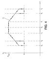
control module 32 can additionally or alternatively be configured to implement hysteresis. For example, as illustrated infigure 4 (the curve P1 represents the way the active power incjected into the grid from a wind power installation varies in accordance with the actual network frequency), the control module can be configured to control the active power PA that is injected into said network from said wind power installation in view of the measured actual network frequency (fa) at which the network is operating, by - reducing the amount of active power injected into the network (for example, from a level Pmax corresponding to a maximum amount of active power that can be generated and output from the wind power installation), as a function of the actual network frequency (that is, in accordance with "rules" based on said actual network frequency, as mentioned above), if said actual network frequency increases beyond a first upper network frequency threshold value (f1) (which could correspond to, for example, 50.2 Hz), and
- stopping injection of active power into the network if said actual network frequency increases beyond a second upper network frequency threshold value (f2) higher than said first upper frequency threshold value (f1).
Further, thecontrol module 32 can be configured such that once said actual network frequency has increased beyond said second upper network frequency threshold value (f2) (this second upper network frequency threshold value (f2) can, for example, be 51.5 Hz), injection of active power into the network is not resumed until the actual network frequency has decreased below a third upper frequency threshold value (f3) lower than said second upper frequency threshold value (f2). That is, if f1=50.2 Hz and f2=51.5 Hz, f3 could be set to a value slightly below 51.5 Hz, such as at 51.2 or 51.0 Hz. By using this third upper frequency threshold value, it is achieved that injection of active power does not resume until the actual network frequency has decreased sufficiently below the second upper frequency threshold value, so as to "guarantee" or at least make it likely that a restart of the injection of active power will not immediately "push" the network frequency upwards beyond the second upper frequency threshold value. Thus, "oscillations" in the on/off status of the injection of active power can be avoided, which can serve to increase the stability of the system.
Further, as illustrated in the left part offigure 4 , thecontrol module 32 can further be configured so as to - reduce the active power injected into the network, as a function of the actual network frequency, if said actual network frequency decreases below a first lower network frequency threshold value (f4) (which could be, for example, 49.8 Hz), and - stop injection of active power into the network if said actual network frequency decreases below a second lower network frequency threshold value (f5) lower than said first lower frequency threshold value (f4), and further so as to,
- once said actual network frequency has decreased below said second lower network frequency threshold value (f5) (which can be, for example, 47.5 Hz), not resume injection of active power into the network until the actual network frequency has increased beyond a third lower frequency threshold value (f6) higher than said second lower frequency threshold value (f5). Thus, "oscillations" in the on/off status of the injection of active power can be avoided also in the range of frequencies lower than the nominal network frequency, which can serve to further increase the stability of the system.
- As an alternative, the control module can be configured to increase (instead of reducing) the amount of active power injected into the network, as a function of the actual network frequency (and as long as such an increase is possible in view of the output limitations of the wind power installation), if said actual network frequency decreases below a first lower network frequency threshold value (f4), until, for example, said actual network frequency sinks below the second lower frequency threshold value (f5). Once below said second lower frequency threshold value, the injected active power can, for example, be kept constant, or be reduced, or be further increased, or even be set to zero, depending on grid codes or on the preferences of the operator of the network or the operator of the wind power installation. For example, in accordance with one possible embodiment, the control module can be configured to stop injection of active power into the network if said actual network frequency decreases below said second lower network frequency threshold value (f5) lower than said first lower frequency threshold value (f4), and further be configured so that, once said actual network frequency has decreased below said second lower network frequency threshold value (f5), injection of active power into the network is not resumed until the actual network frequency has increased beyond a third lower frequency threshold value (f6) higher than said second lower frequency threshold value (f5).
-
Figure 5 illustrates two such possible embodiments of the invention. In a first one, corresponding to the power curve P2, the power injected into the network from the wind power installation is at the maximum level Pmax when the actual network frequency corresponds to the nominal network frequency fn. When the actual network frequency increases beyond f1, power injection is reduced, and finally stopped when the frequency increases beyond f2, not to be resumed again until the frequency has decreased below f3, just as described in connection withfigure 4 . - However, the difference compared to the P1 embodiment is that in accordance with the P2 embodiment, the injected power is not decreased when the actual frequency sinks below f4; instead, the maximum available active power is continued to be injected into the grid, until the actual frequency sinks below f5, in which case power injection is stopped, not to be resumed again until the frequency rises above f6.
- A further embodiment is illustrated by the power curve P3, similar to P2 but with the difference that at network frequencies at fn and up until f1, the amount of active power injected into the network is not the maximum power that could be supplied by the wind power installation, but a lower amount of active power, reduced by an amount X which constitutes a so-called "power reserve" or "spinning reserve". This makes it possible to increase the amount of active power when the actual network frequency sinks below the first lower network frequency threshold value f4, until the maximum Pmax is reached, as shown in
figure 5 (also here, injection can be stopped at f5 and resumed at f6). In this way, the arrangement helps to further stabilise the system, as the insufficient injection of active power that caused the decrease of the actual network frequency can be at least partly compensated by the "power reserve". - In under-frequency situations, the frequently employed reduction of the injected active power is often basically related to internal limitations in the turbine. However, from a system/grid point of view, when the actual frequency in the grid sinks below the desired value, it can be better to increase the amount of active power injected into the grid. Of course, this requires some kind of "power reserve" in the wind turbine, that is, a capacity to produce and inject into the grid more active power than what was previously produced.
-
Figures 7A and 7B schematically illustrate two basic controller concepts that can be useful to implement different embodiments of the invention. Infigure 7A , a two-level hysteresis controller is illustrated, with a first input signal fref (that could correspond to a "desired" value of, for example, a frequency, such as the nominal frequency fn referred to above) and a second input signal fm (which could be a measured "real" value of a frequency, such as the actual grid frequency fa referred to above), and an output signal which can have two different levels (for example, "0" or "1"), whereby the level of the output signal depends on the difference between the two input signals. -
Figure 7B illustrates a similar concept, but with an output signal that can have three different levels, such as "-1 ", "0" and "1". - In this text, the term "comprises" and its derivations (such as "comprising", etc.) should not be understood in an excluding sense, that is, these terms should not be interpreted as excluding the possibility that what is described and defined may include further elements, steps, etc.
- On the other hand, the invention is obviously not limited to the specific embodiment(s) described herein, but also encompasses any variations that may be considered by any person skilled in the art (for example, as regards the choice of materials, dimensions, components, configuration, etc.), within the general scope of the invention as defined in the claims.
Claims (17)
- Method of operating a wind power installation connected to a network (2) for distribution of electrical power, said wind power installation comprising at least one wind power generator (1), said wind power installation being related to said network for injection of power into said network, said network having a nominal network frequency (fn) and said network being arranged for operating at said nominal network frequency, wherein said method comprises controlling the active power that is injected into said network from said wind power installation in view of a measured actual network frequency (fa) at which the network is operating, said method comprising the steps of- measuring said actual network frequency (fa); and- determining a difference (E) between said actual network frequency (fa) and said nominal network frequency (fn);characterised in that
said method further comprises the step of, if said difference is larger than a predefined threshold, adapting the amount of active power that is injected into the network from said wind power installation, in a manner so as to bring the actual network frequency (fa) back towards the nominal network frequency (fn). - Method according to claim 1, wherein said active power that is injected into the network is adapted using a controller (3) involving at least an integration over time of said difference (E) between said actual network frequency (fa) and said nominal network frequency (fn).
- Method according to claim 2, wherein said controller is a PI controller.
- Method according to claim 2, wherein said controller is a PID controller.
- Method according to claim 2, wherein said controller is an I controller.
- Method according to claim 2, wherein said controller is an ID controller.
- Method according to claim 1, wherein said active power that is injected into the network is adapted using a controller involving at least a time derivative of said difference (E) between said actual network frequency (fa) and said nominal network frequency (fn).
- Method according to claim 7, wherein said controller is a ID controller.
- Method according to claim 7, wherein said controller is a PID controller.
- Method according to claim 7, wherein said controller is a D controller.
- Method according to claim 7, wherein said controller is a PD controller.
- Method of operating a wind power installation connected to a network (2) for distribution of electrical power, said wind power installation comprising at least one wind power generator (1), said wind power installation being related to said network for injection of power into said network, said network having a nominal network frequency (fn) and said network being arranged for operating at said nominal network frequency, wherein said method comprises controlling the active power that is injected into said network from said wind power installation in view of a measured actual network frequency (fa) at which the network is operating, said method comprising the steps of- reducing the active power injected into the network, as a function of the actual network frequency, if said actual network frequency increases beyond a first upper network frequency threshold value (f1),
and- stopping injection of active power into the network if said actual network frequency increases beyond a second upper network frequency threshold value (f2) higher than said first upper frequency threshold value (f1),characterised in that
once said actual network frequency has increased beyond said second upper network frequency threshold value (f2), injection of active power into the network is not resumed until the actual network frequency has decreased below a third upper frequency threshold value(f3) lower than said second upper frequency threshold value (f2). - Method according to claim 12, wherein said method further comprises the steps of- reducing the active power injected into the network, as a function of the actual network frequency, if said actual network frequency decreases below a first lower network frequency threshold value (f4),
and- stopping injection of active power into the network if said actual network frequency decreases below a second lower network frequency threshold value (f5) lower than said first lower frequency threshold value (f4), wherein, once said actual network frequency has decreased below said second lower network frequency threshold value (f5), injection of active power into the network is not resumed until the actual network frequency has increased beyond a third lower frequency threshold value (f6) higher than said second lower frequency threshold value (f5). - Method according to claim 12, wherein said method further comprises the step of- increasing the active power injected into the network, as a function of the actual network frequency, if said actual network frequency decreases below a first lower network frequency threshold value (f4).
- Method according to claim 14, further comprising the step of stopping injection of active power into the network if said actual network frequency decreases below a second lower network frequency threshold value (f5) lower than said first lower frequency threshold value (f4), wherein, once said actual network frequency has decreased below said second lower network frequency threshold value (f5), injection of active power into the network is not resumed until the actual network frequency has increased beyond a third lower frequency threshold value (f6) higher than said second lower frequency threshold value (f5).
- Method of any of claims 12-15, further comprising the method of any of claims 1-11.
- Wind power installation arranged to be connected to a network (2) for distribution of electrical power, said wind power installation comprising at least one wind power generator (1), said wind power installation being related to said network for injection of power into said network, characterised in that
said wind power installation comprises a control system (3) arranged for controlling the injection of active power into the network in accordance with the method of any of the preceding claims.
Priority Applications (1)
| Application Number | Priority Date | Filing Date | Title |
|---|---|---|---|
| PL08021990T PL2075463T3 (en) | 2007-12-27 | 2008-12-18 | Wind power installation and method of operating it |
Applications Claiming Priority (1)
| Application Number | Priority Date | Filing Date | Title |
|---|---|---|---|
| ES200703458A ES2338396B1 (en) | 2007-12-27 | 2007-12-27 | WIND ENERGY INSTALLATION AND PROCEDURE FOR OPERATION. |
Publications (4)
| Publication Number | Publication Date |
|---|---|
| EP2075463A2 true EP2075463A2 (en) | 2009-07-01 |
| EP2075463A3 EP2075463A3 (en) | 2012-01-04 |
| EP2075463B1 EP2075463B1 (en) | 2014-01-08 |
| EP2075463B2 EP2075463B2 (en) | 2021-01-13 |
Family
ID=40538868
Family Applications (1)
| Application Number | Title | Priority Date | Filing Date |
|---|---|---|---|
| EP08021990.0A Active EP2075463B2 (en) | 2007-12-27 | 2008-12-18 | Wind power installation and method of operating it |
Country Status (5)
| Country | Link |
|---|---|
| US (1) | US7982325B2 (en) |
| EP (1) | EP2075463B2 (en) |
| CN (1) | CN101483344B (en) |
| ES (2) | ES2338396B1 (en) |
| PL (1) | PL2075463T3 (en) |
Cited By (10)
| Publication number | Priority date | Publication date | Assignee | Title |
|---|---|---|---|---|
| WO2011006152A3 (en) * | 2009-07-06 | 2011-11-24 | Siemens Energy, Inc. | Frequency-responsive wind turbine output control |
| JP2012112385A (en) * | 2010-11-26 | 2012-06-14 | Siemens Ag | Method and system for controlling electric device of wind turbine |
| EP2532888A1 (en) * | 2011-06-08 | 2012-12-12 | Siemens Aktiengesellschaft | Arrangement for generating a control signal for controlling a power output of a power generation system |
| CN103066627A (en) * | 2013-01-28 | 2013-04-24 | 四川科陆新能电气有限公司 | Grid-connected-operation-based synchronous generator system capable of adjusting active powder in rotating speed mode and adjusting method of system |
| EP2626555A1 (en) * | 2012-02-08 | 2013-08-14 | Siemens Aktiengesellschaft | Method and arrangement for controlling a wind turbine using oscillation detection |
| WO2013167142A1 (en) * | 2012-05-11 | 2013-11-14 | Vestas Wind Systems A/S | Wind power plant frequency control |
| CN104113088A (en) * | 2014-08-04 | 2014-10-22 | 国网吉林省电力有限公司 | Wind power cluster control system |
| CN105449725A (en) * | 2015-12-22 | 2016-03-30 | 新疆金风科技股份有限公司 | Direct-drive wind generating set frequency crossing method and device |
| EP2780727B1 (en) * | 2011-11-14 | 2018-08-15 | Emeter Corporation | Smart meters, and systems and method for electrical power reconnection |
| CN109217383A (en) * | 2018-09-30 | 2019-01-15 | 国电联合动力技术有限公司 | A kind of wisdom wind power plant parameter adaptive fast frequency hopping control method and system |
Families Citing this family (25)
| Publication number | Priority date | Publication date | Assignee | Title |
|---|---|---|---|---|
| DE102009014012B4 (en) | 2009-03-23 | 2014-02-13 | Wobben Properties Gmbh | Method for operating a wind energy plant |
| WO2010108979A2 (en) * | 2009-03-25 | 2010-09-30 | Vestas Wind Systems A/S | Improved frequency control |
| US8219256B2 (en) | 2009-07-14 | 2012-07-10 | Siemens Aktiengesellschaft | Bang-bang controller and control method for variable speed wind turbines during abnormal frequency conditions |
| FR2956531B1 (en) * | 2010-02-18 | 2012-03-30 | Vergnet Sa | WINDMILL ASSOCIATED WITH AN ENERGY STORAGE SYSTEM COMPRISING AT LEAST ONE INVERTER / RECTIFIER CONVERTER FOR SUPPORTING AN ELECTRICAL NETWORK BY MONITORING THE FREQUENCY |
| FR2956532B1 (en) * | 2010-02-18 | 2012-03-30 | Vergnet Sa | WIND TURBINE ASSOCIATED WITH AN ENERGY STORAGE SYSTEM COMPRISING AT LEAST ONE HASTER FOR THE SUPPORT OF AN ELECTRICITY NETWORK BY FREQUENCY MONITORING |
| CN101860042B (en) * | 2010-05-14 | 2012-09-26 | 许继集团有限公司 | Method for cooperatively controlling active power of wind farm |
| BRPI1005389A2 (en) | 2010-06-16 | 2016-08-16 | Mitsubishi Heavy Ind Ltd | wind turbine generator control device and method for controlling it |
| CN102374118B (en) * | 2010-08-11 | 2013-06-12 | 华锐风电科技(江苏)有限公司 | Power control method for wind generating set |
| DK2572426T3 (en) * | 2010-08-13 | 2014-07-21 | Siemens Ag | Device for generating a control signal for controlling a power output from a power generation system |
| CA2724601C (en) * | 2010-08-26 | 2013-10-29 | Mitsubishi Heavy Industries, Ltd. | Wind turbine generator and output power control method |
| CN101997312A (en) * | 2010-12-08 | 2011-03-30 | 浙江省电力试验研究院 | Method for quickly and effectively inhibiting frequency fluctuation of island power grid |
| DK2557678T3 (en) * | 2011-08-09 | 2014-06-02 | Siemens Ag | Device for generating a control signal for controlling an acceleration of a generator |
| US8736094B2 (en) | 2012-01-20 | 2014-05-27 | Mitsubishi Heavy Industries, Ltd. | Wind-turbine-generator control system, wind turbine generator, wind farm, and wind-turbine-generator control method |
| DK2629386T3 (en) * | 2012-02-16 | 2018-04-16 | Ge Renewable Tech | PROCEDURE TO AVOID VOLTAGE INSTABILITY IN A OFFSHORE WINDOW PARK PARK |
| JP5325348B1 (en) * | 2012-02-24 | 2013-10-23 | 三菱重工業株式会社 | Windmill control device and method, and wind power generation system |
| DE102012212777A1 (en) | 2012-07-20 | 2014-01-23 | Wobben Properties Gmbh | Method for controlling a wind farm |
| US20140203560A1 (en) * | 2013-01-22 | 2014-07-24 | General Electric Company | Wind turbine and method for adjusting rotor blade pitch angle in wind turbine |
| DE102013207264A1 (en) * | 2013-04-22 | 2014-10-23 | Wobben Properties Gmbh | Method for controlling a wind farm |
| DE102014200737A1 (en) * | 2014-01-16 | 2015-07-16 | Wobben Properties Gmbh | Method and control and / or control device for operating a wind turbine and / or a wind farm and wind turbine and wind farm |
| US9771823B2 (en) * | 2014-06-26 | 2017-09-26 | General Electric Company | Power generation system control following transient grid event |
| US20160013646A1 (en) * | 2014-07-14 | 2016-01-14 | Heart Transverter, S.A. | Load management, metering, and demand response module |
| ES2818048T3 (en) | 2015-08-31 | 2021-04-09 | Otis Elevator Co | Automatic commissioning of controller for active three-phase power electronic converters |
| DE102016103101A1 (en) * | 2016-02-23 | 2017-08-24 | Wobben Properties Gmbh | Method and wind farm control module for controlling a wind farm |
| DE102016120700A1 (en) | 2016-10-28 | 2018-05-03 | Wobben Properties Gmbh | Method for operating a wind energy plant |
| US20180230969A1 (en) * | 2017-02-10 | 2018-08-16 | Leeward Asset Management, LLC | Methods and systems for wind farm frequency control |
Citations (2)
| Publication number | Priority date | Publication date | Assignee | Title |
|---|---|---|---|---|
| DE10022974A1 (en) | 2000-05-11 | 2001-11-22 | Aloys Wobben | Control of wind power generator plant feeding grid, regulates power delivery as a function of measured grid frequency |
| DE102005052011A1 (en) | 2005-10-31 | 2007-05-03 | E.On Netz Gmbh | Wind energy plant operating method, involves dynamically changing electrical active power during exceeding main frequency threshold value by specific hertz depending on current main frequency in accordance with specific relationship |
Family Cites Families (9)
| Publication number | Priority date | Publication date | Assignee | Title |
|---|---|---|---|---|
| DE3909041A1 (en) * | 1989-03-18 | 1990-09-20 | Bosch Gmbh Robert | CONTROL ARRANGEMENT |
| US6600240B2 (en) * | 1997-08-08 | 2003-07-29 | General Electric Company | Variable speed wind turbine generator |
| US6219623B1 (en) * | 1997-11-24 | 2001-04-17 | Plug Power, Inc. | Anti-islanding method and apparatus for distributed power generation |
| ES2189664B1 (en) * | 2001-09-13 | 2004-10-16 | Made Tecnologias Renovables, S.A. | SYSTEM FOR THE USE OF THE ENERGY STORED IN THE MECHANICAL INERTIA OF THE ROTOR OF A WIND TURBINE. |
| ES2619198T3 (en) * | 2003-04-09 | 2017-06-23 | General Electric Company | Wind farm and its operation procedure |
| US7149605B2 (en) † | 2003-06-13 | 2006-12-12 | Battelle Memorial Institute | Electrical power distribution control methods, electrical energy demand monitoring methods, and power management devices |
| US7239036B2 (en) * | 2005-07-29 | 2007-07-03 | General Electric Company | System and method for power control in wind turbines |
| US7345373B2 (en) * | 2005-11-29 | 2008-03-18 | General Electric Company | System and method for utility and wind turbine control |
| US7312537B1 (en) * | 2006-06-19 | 2007-12-25 | General Electric Company | Methods and apparatus for supplying and/or absorbing reactive power |
-
2007
- 2007-12-27 ES ES200703458A patent/ES2338396B1/en not_active Expired - Fee Related
-
2008
- 2008-12-11 US US12/332,467 patent/US7982325B2/en active Active
- 2008-12-18 EP EP08021990.0A patent/EP2075463B2/en active Active
- 2008-12-18 ES ES08021990T patent/ES2453840T5/en active Active
- 2008-12-18 PL PL08021990T patent/PL2075463T3/en unknown
- 2008-12-25 CN CN2008101865658A patent/CN101483344B/en active Active
Patent Citations (2)
| Publication number | Priority date | Publication date | Assignee | Title |
|---|---|---|---|---|
| DE10022974A1 (en) | 2000-05-11 | 2001-11-22 | Aloys Wobben | Control of wind power generator plant feeding grid, regulates power delivery as a function of measured grid frequency |
| DE102005052011A1 (en) | 2005-10-31 | 2007-05-03 | E.On Netz Gmbh | Wind energy plant operating method, involves dynamically changing electrical active power during exceeding main frequency threshold value by specific hertz depending on current main frequency in accordance with specific relationship |
Cited By (20)
| Publication number | Priority date | Publication date | Assignee | Title |
|---|---|---|---|---|
| JP2013501484A (en) * | 2009-07-06 | 2013-01-10 | シーメンス アクチエンゲゼルシヤフト | Wind turbine output control according to frequency |
| WO2011006152A3 (en) * | 2009-07-06 | 2011-11-24 | Siemens Energy, Inc. | Frequency-responsive wind turbine output control |
| CN102510946A (en) * | 2009-07-06 | 2012-06-20 | 西门子公司 | Frequency-responsive wind turbine output control |
| US8301311B2 (en) | 2009-07-06 | 2012-10-30 | Siemens Aktiengesellschaft | Frequency-responsive wind turbine output control |
| CN102510946B (en) * | 2009-07-06 | 2015-01-14 | 西门子公司 | Frequency-responsive wind turbine output control |
| EP2458205B1 (en) * | 2010-11-26 | 2016-10-19 | Siemens Aktiengesellschaft | Method and system for controlling an electric device of a wind turbine |
| JP2012112385A (en) * | 2010-11-26 | 2012-06-14 | Siemens Ag | Method and system for controlling electric device of wind turbine |
| US9261079B2 (en) | 2011-06-08 | 2016-02-16 | Siemens Aktiengesellschaft | Arrangement for generating a control signal for controlling a power output of a power generation system |
| EP2532888A1 (en) * | 2011-06-08 | 2012-12-12 | Siemens Aktiengesellschaft | Arrangement for generating a control signal for controlling a power output of a power generation system |
| EP2780727B1 (en) * | 2011-11-14 | 2018-08-15 | Emeter Corporation | Smart meters, and systems and method for electrical power reconnection |
| US8823191B2 (en) | 2012-02-08 | 2014-09-02 | Siemens Aktiengesellschaft | Method and arrangement for controlling a wind turbine using oscillation detection |
| EP2626555A1 (en) * | 2012-02-08 | 2013-08-14 | Siemens Aktiengesellschaft | Method and arrangement for controlling a wind turbine using oscillation detection |
| WO2013167142A1 (en) * | 2012-05-11 | 2013-11-14 | Vestas Wind Systems A/S | Wind power plant frequency control |
| EP2847458B1 (en) | 2012-05-11 | 2017-08-16 | Vestas Wind Systems A/S | Wind power plant frequency control |
| US9915244B2 (en) | 2012-05-11 | 2018-03-13 | Vestas Wind Systems A/S | Wind power plant frequency control |
| CN103066627A (en) * | 2013-01-28 | 2013-04-24 | 四川科陆新能电气有限公司 | Grid-connected-operation-based synchronous generator system capable of adjusting active powder in rotating speed mode and adjusting method of system |
| CN103066627B (en) * | 2013-01-28 | 2016-07-06 | 四川科陆新能电气有限公司 | The control method of the synchronous generator system that is incorporated into the power networks of active power can be regulated under rotating speed pattern |
| CN104113088A (en) * | 2014-08-04 | 2014-10-22 | 国网吉林省电力有限公司 | Wind power cluster control system |
| CN105449725A (en) * | 2015-12-22 | 2016-03-30 | 新疆金风科技股份有限公司 | Direct-drive wind generating set frequency crossing method and device |
| CN109217383A (en) * | 2018-09-30 | 2019-01-15 | 国电联合动力技术有限公司 | A kind of wisdom wind power plant parameter adaptive fast frequency hopping control method and system |
Also Published As
| Publication number | Publication date |
|---|---|
| CN101483344A (en) | 2009-07-15 |
| ES2453840T5 (en) | 2021-11-04 |
| US20090167021A1 (en) | 2009-07-02 |
| PL2075463T3 (en) | 2014-06-30 |
| EP2075463A3 (en) | 2012-01-04 |
| US7982325B2 (en) | 2011-07-19 |
| ES2338396B1 (en) | 2011-04-08 |
| ES2453840T3 (en) | 2014-04-08 |
| EP2075463B2 (en) | 2021-01-13 |
| ES2338396A1 (en) | 2010-05-06 |
| CN101483344B (en) | 2013-04-03 |
| EP2075463B1 (en) | 2014-01-08 |
Similar Documents
| Publication | Publication Date | Title |
|---|---|---|
| EP2075463B1 (en) | Wind power installation and method of operating it | |
| EP3068007B1 (en) | System and method for improved reactive power speed-of-response for a wind farm | |
| CN105917542B (en) | Wind power plant, wind farm, method for operating the wind power plant, and control and/or regulation device | |
| RU2648269C2 (en) | Method for feeding electrical power into an electrical supply network | |
| RU2653616C2 (en) | Method for controlling wind park | |
| EP1672779B1 (en) | Wind farm power ramp rate control system and method | |
| EP2594005B1 (en) | Power oscillation damping controller | |
| JP4604111B2 (en) | Wind power generator and wind power generator group | |
| US20100066086A1 (en) | Apparatus and system for pitch angle control of wind turbine | |
| US11098694B2 (en) | Method of controlling a wind turbine generator | |
| TWI599135B (en) | Method and regulation and/or control device for operating a wind turbine and/or a wind farm, and wind turbine and wind farm | |
| US10868427B2 (en) | Method for feeding electrical power into an electrical supply network | |
| CN115467779A (en) | Method of operating a wind turbine, corresponding wind turbine and wind park | |
| WO2022194330A1 (en) | Methods and systems for damping power oscillations during frequency fluctuations | |
| US11916396B2 (en) | Systems and methods for control of power generation assets | |
| Khatami et al. | Two-area frequency control in overloaded conditions by using HVDC transmission | |
| US20240003334A1 (en) | Active power boosting in wind power plants | |
| JP2004159466A (en) | Method and apparatus for preventing reverse power flow in electric power plant |
Legal Events
| Date | Code | Title | Description |
|---|---|---|---|
| PUAI | Public reference made under article 153(3) epc to a published international application that has entered the european phase |
Free format text: ORIGINAL CODE: 0009012 |
|
| AK | Designated contracting states |
Kind code of ref document: A2 Designated state(s): AT BE BG CH CY CZ DE DK EE ES FI FR GB GR HR HU IE IS IT LI LT LU LV MC MT NL NO PL PT RO SE SI SK TR |
|
| AX | Request for extension of the european patent |
Extension state: AL BA MK RS |
|
| PUAL | Search report despatched |
Free format text: ORIGINAL CODE: 0009013 |
|
| AK | Designated contracting states |
Kind code of ref document: A3 Designated state(s): AT BE BG CH CY CZ DE DK EE ES FI FR GB GR HR HU IE IS IT LI LT LU LV MC MT NL NO PL PT RO SE SI SK TR |
|
| AX | Request for extension of the european patent |
Extension state: AL BA MK RS |
|
| RIC1 | Information provided on ipc code assigned before grant |
Ipc: H02J 3/40 20060101ALI20111125BHEP Ipc: F03D 9/00 20060101ALI20111125BHEP Ipc: H02J 3/38 20060101ALI20111125BHEP Ipc: F03D 7/04 20060101AFI20111125BHEP Ipc: H02P 9/42 20060101ALI20111125BHEP |
|
| 17P | Request for examination filed |
Effective date: 20120123 |
|
| AKX | Designation fees paid |
Designated state(s): AT BE BG CH CY CZ DE DK EE ES FI FR GB GR HR HU IE IS IT LI LT LU LV MC MT NL NO PL PT RO SE SI SK TR |
|
| REG | Reference to a national code |
Ref country code: DE Ref legal event code: R079 Ref document number: 602008029714 Country of ref document: DE Free format text: PREVIOUS MAIN CLASS: F03D0007040000 Ipc: F03D0007020000 |
|
| GRAP | Despatch of communication of intention to grant a patent |
Free format text: ORIGINAL CODE: EPIDOSNIGR1 |
|
| RIC1 | Information provided on ipc code assigned before grant |
Ipc: H02P 9/00 20060101ALI20130715BHEP Ipc: H02P 9/42 20060101ALI20130715BHEP Ipc: F03D 7/02 20060101AFI20130715BHEP Ipc: F03D 7/04 20060101ALI20130715BHEP Ipc: H02J 3/48 20060101ALI20130715BHEP Ipc: H02J 3/38 20060101ALI20130715BHEP Ipc: F03D 9/00 20060101ALI20130715BHEP |
|
| INTG | Intention to grant announced |
Effective date: 20130812 |
|
| GRAS | Grant fee paid |
Free format text: ORIGINAL CODE: EPIDOSNIGR3 |
|
| GRAA | (expected) grant |
Free format text: ORIGINAL CODE: 0009210 |
|
| AK | Designated contracting states |
Kind code of ref document: B1 Designated state(s): AT BE BG CH CY CZ DE DK EE ES FI FR GB GR HR HU IE IS IT LI LT LU LV MC MT NL NO PL PT RO SE SI SK TR |
|
| REG | Reference to a national code |
Ref country code: GB Ref legal event code: FG4D |
|
| REG | Reference to a national code |
Ref country code: CH Ref legal event code: EP |
|
| REG | Reference to a national code |
Ref country code: IE Ref legal event code: FG4D |
|
| REG | Reference to a national code |
Ref country code: AT Ref legal event code: REF Ref document number: 648915 Country of ref document: AT Kind code of ref document: T Effective date: 20140215 |
|
| REG | Reference to a national code |
Ref country code: DE Ref legal event code: R096 Ref document number: 602008029714 Country of ref document: DE Effective date: 20140220 |
|
| REG | Reference to a national code |
Ref country code: SE Ref legal event code: TRGR |
|
| REG | Reference to a national code |
Ref country code: ES Ref legal event code: FG2A Ref document number: 2453840 Country of ref document: ES Kind code of ref document: T3 Effective date: 20140408 |
|
| REG | Reference to a national code |
Ref country code: AT Ref legal event code: MK05 Ref document number: 648915 Country of ref document: AT Kind code of ref document: T Effective date: 20140108 |
|
| REG | Reference to a national code |
Ref country code: NL Ref legal event code: VDEP Effective date: 20140108 |
|
| REG | Reference to a national code |
Ref country code: LT Ref legal event code: MG4D |
|
| REG | Reference to a national code |
Ref country code: PL Ref legal event code: T3 |
|
| RAP2 | Party data changed (patent owner data changed or rights of a patent transferred) |
Owner name: GAMESA INNOVATION & TECHNOLOGY, S.L. |
|
| PG25 | Lapsed in a contracting state [announced via postgrant information from national office to epo] |
Ref country code: NO Free format text: LAPSE BECAUSE OF FAILURE TO SUBMIT A TRANSLATION OF THE DESCRIPTION OR TO PAY THE FEE WITHIN THE PRESCRIBED TIME-LIMIT Effective date: 20140408 Ref country code: LT Free format text: LAPSE BECAUSE OF FAILURE TO SUBMIT A TRANSLATION OF THE DESCRIPTION OR TO PAY THE FEE WITHIN THE PRESCRIBED TIME-LIMIT Effective date: 20140108 Ref country code: IS Free format text: LAPSE BECAUSE OF FAILURE TO SUBMIT A TRANSLATION OF THE DESCRIPTION OR TO PAY THE FEE WITHIN THE PRESCRIBED TIME-LIMIT Effective date: 20140508 |
|
| PG25 | Lapsed in a contracting state [announced via postgrant information from national office to epo] |
Ref country code: NL Free format text: LAPSE BECAUSE OF FAILURE TO SUBMIT A TRANSLATION OF THE DESCRIPTION OR TO PAY THE FEE WITHIN THE PRESCRIBED TIME-LIMIT Effective date: 20140108 Ref country code: AT Free format text: LAPSE BECAUSE OF FAILURE TO SUBMIT A TRANSLATION OF THE DESCRIPTION OR TO PAY THE FEE WITHIN THE PRESCRIBED TIME-LIMIT Effective date: 20140108 Ref country code: PT Free format text: LAPSE BECAUSE OF FAILURE TO SUBMIT A TRANSLATION OF THE DESCRIPTION OR TO PAY THE FEE WITHIN THE PRESCRIBED TIME-LIMIT Effective date: 20140508 Ref country code: CY Free format text: LAPSE BECAUSE OF FAILURE TO SUBMIT A TRANSLATION OF THE DESCRIPTION OR TO PAY THE FEE WITHIN THE PRESCRIBED TIME-LIMIT Effective date: 20140108 |
|
| PG25 | Lapsed in a contracting state [announced via postgrant information from national office to epo] |
Ref country code: BE Free format text: LAPSE BECAUSE OF FAILURE TO SUBMIT A TRANSLATION OF THE DESCRIPTION OR TO PAY THE FEE WITHIN THE PRESCRIBED TIME-LIMIT Effective date: 20140108 Ref country code: LV Free format text: LAPSE BECAUSE OF FAILURE TO SUBMIT A TRANSLATION OF THE DESCRIPTION OR TO PAY THE FEE WITHIN THE PRESCRIBED TIME-LIMIT Effective date: 20140108 Ref country code: HR Free format text: LAPSE BECAUSE OF FAILURE TO SUBMIT A TRANSLATION OF THE DESCRIPTION OR TO PAY THE FEE WITHIN THE PRESCRIBED TIME-LIMIT Effective date: 20140108 |
|
| REG | Reference to a national code |
Ref country code: DE Ref legal event code: R026 Ref document number: 602008029714 Country of ref document: DE |
|
| PLBI | Opposition filed |
Free format text: ORIGINAL CODE: 0009260 |
|
| PLBI | Opposition filed |
Free format text: ORIGINAL CODE: 0009260 |
|
| PG25 | Lapsed in a contracting state [announced via postgrant information from national office to epo] |
Ref country code: RO Free format text: LAPSE BECAUSE OF FAILURE TO SUBMIT A TRANSLATION OF THE DESCRIPTION OR TO PAY THE FEE WITHIN THE PRESCRIBED TIME-LIMIT Effective date: 20140108 Ref country code: DK Free format text: LAPSE BECAUSE OF FAILURE TO SUBMIT A TRANSLATION OF THE DESCRIPTION OR TO PAY THE FEE WITHIN THE PRESCRIBED TIME-LIMIT Effective date: 20140108 Ref country code: CZ Free format text: LAPSE BECAUSE OF FAILURE TO SUBMIT A TRANSLATION OF THE DESCRIPTION OR TO PAY THE FEE WITHIN THE PRESCRIBED TIME-LIMIT Effective date: 20140108 Ref country code: EE Free format text: LAPSE BECAUSE OF FAILURE TO SUBMIT A TRANSLATION OF THE DESCRIPTION OR TO PAY THE FEE WITHIN THE PRESCRIBED TIME-LIMIT Effective date: 20140108 |
|
| 26 | Opposition filed |
Opponent name: VESTAS WIND SYSTEMS A/S Effective date: 20140930 |
|
| 26 | Opposition filed |
Opponent name: ENERCON GMBH Effective date: 20141008 |
|
| PLAX | Notice of opposition and request to file observation + time limit sent |
Free format text: ORIGINAL CODE: EPIDOSNOBS2 |
|
| PG25 | Lapsed in a contracting state [announced via postgrant information from national office to epo] |
Ref country code: SK Free format text: LAPSE BECAUSE OF FAILURE TO SUBMIT A TRANSLATION OF THE DESCRIPTION OR TO PAY THE FEE WITHIN THE PRESCRIBED TIME-LIMIT Effective date: 20140108 |
|
| REG | Reference to a national code |
Ref country code: DE Ref legal event code: R026 Ref document number: 602008029714 Country of ref document: DE Effective date: 20140930 |
|
| PLBB | Reply of patent proprietor to notice(s) of opposition received |
Free format text: ORIGINAL CODE: EPIDOSNOBS3 |
|
| PG25 | Lapsed in a contracting state [announced via postgrant information from national office to epo] |
Ref country code: SI Free format text: LAPSE BECAUSE OF FAILURE TO SUBMIT A TRANSLATION OF THE DESCRIPTION OR TO PAY THE FEE WITHIN THE PRESCRIBED TIME-LIMIT Effective date: 20140108 |
|
| PG25 | Lapsed in a contracting state [announced via postgrant information from national office to epo] |
Ref country code: LU Free format text: LAPSE BECAUSE OF FAILURE TO SUBMIT A TRANSLATION OF THE DESCRIPTION OR TO PAY THE FEE WITHIN THE PRESCRIBED TIME-LIMIT Effective date: 20141218 |
|
| REG | Reference to a national code |
Ref country code: CH Ref legal event code: PL |
|
| REG | Reference to a national code |
Ref country code: IE Ref legal event code: MM4A |
|
| REG | Reference to a national code |
Ref country code: FR Ref legal event code: PLFP Year of fee payment: 8 |
|
| PG25 | Lapsed in a contracting state [announced via postgrant information from national office to epo] |
Ref country code: IE Free format text: LAPSE BECAUSE OF NON-PAYMENT OF DUE FEES Effective date: 20141218 Ref country code: CH Free format text: LAPSE BECAUSE OF NON-PAYMENT OF DUE FEES Effective date: 20141231 Ref country code: LI Free format text: LAPSE BECAUSE OF NON-PAYMENT OF DUE FEES Effective date: 20141231 |
|
| PLBP | Opposition withdrawn |
Free format text: ORIGINAL CODE: 0009264 |
|
| PG25 | Lapsed in a contracting state [announced via postgrant information from national office to epo] |
Ref country code: MC Free format text: LAPSE BECAUSE OF FAILURE TO SUBMIT A TRANSLATION OF THE DESCRIPTION OR TO PAY THE FEE WITHIN THE PRESCRIBED TIME-LIMIT Effective date: 20140108 Ref country code: BG Free format text: LAPSE BECAUSE OF FAILURE TO SUBMIT A TRANSLATION OF THE DESCRIPTION OR TO PAY THE FEE WITHIN THE PRESCRIBED TIME-LIMIT Effective date: 20140108 |
|
| PG25 | Lapsed in a contracting state [announced via postgrant information from national office to epo] |
Ref country code: GR Free format text: LAPSE BECAUSE OF FAILURE TO SUBMIT A TRANSLATION OF THE DESCRIPTION OR TO PAY THE FEE WITHIN THE PRESCRIBED TIME-LIMIT Effective date: 20140108 |
|
| PG25 | Lapsed in a contracting state [announced via postgrant information from national office to epo] |
Ref country code: TR Free format text: LAPSE BECAUSE OF FAILURE TO SUBMIT A TRANSLATION OF THE DESCRIPTION OR TO PAY THE FEE WITHIN THE PRESCRIBED TIME-LIMIT Effective date: 20140108 Ref country code: MT Free format text: LAPSE BECAUSE OF FAILURE TO SUBMIT A TRANSLATION OF THE DESCRIPTION OR TO PAY THE FEE WITHIN THE PRESCRIBED TIME-LIMIT Effective date: 20140108 Ref country code: HU Free format text: LAPSE BECAUSE OF FAILURE TO SUBMIT A TRANSLATION OF THE DESCRIPTION OR TO PAY THE FEE WITHIN THE PRESCRIBED TIME-LIMIT; INVALID AB INITIO Effective date: 20081218 |
|
| REG | Reference to a national code |
Ref country code: FR Ref legal event code: PLFP Year of fee payment: 9 |
|
| APBM | Appeal reference recorded |
Free format text: ORIGINAL CODE: EPIDOSNREFNO |
|
| APBP | Date of receipt of notice of appeal recorded |
Free format text: ORIGINAL CODE: EPIDOSNNOA2O |
|
| APAH | Appeal reference modified |
Free format text: ORIGINAL CODE: EPIDOSCREFNO |
|
| APBQ | Date of receipt of statement of grounds of appeal recorded |
Free format text: ORIGINAL CODE: EPIDOSNNOA3O |
|
| REG | Reference to a national code |
Ref country code: FR Ref legal event code: PLFP Year of fee payment: 10 |
|
| PGFP | Annual fee paid to national office [announced via postgrant information from national office to epo] |
Ref country code: SE Payment date: 20181210 Year of fee payment: 11 Ref country code: FI Payment date: 20181220 Year of fee payment: 11 |
|
| PGFP | Annual fee paid to national office [announced via postgrant information from national office to epo] |
Ref country code: CH Payment date: 20190308 Year of fee payment: 8 Ref country code: IT Payment date: 20181220 Year of fee payment: 11 |
|
| APAH | Appeal reference modified |
Free format text: ORIGINAL CODE: EPIDOSCREFNO |
|
| REG | Reference to a national code |
Ref country code: DE Ref legal event code: R119 Ref document number: 602008029714 Country of ref document: DE Ref country code: DE Ref legal event code: R409 Ref document number: 602008029714 Country of ref document: DE |
|
| REG | Reference to a national code |
Ref country code: FI Ref legal event code: MAE |
|
| REG | Reference to a national code |
Ref country code: SE Ref legal event code: EUG |
|
| PG25 | Lapsed in a contracting state [announced via postgrant information from national office to epo] |
Ref country code: FI Free format text: LAPSE BECAUSE OF NON-PAYMENT OF DUE FEES Effective date: 20191218 |
|
| APBU | Appeal procedure closed |
Free format text: ORIGINAL CODE: EPIDOSNNOA9O |
|
| PG25 | Lapsed in a contracting state [announced via postgrant information from national office to epo] |
Ref country code: SE Free format text: LAPSE BECAUSE OF NON-PAYMENT OF DUE FEES Effective date: 20191219 Ref country code: IT Free format text: LAPSE BECAUSE OF NON-PAYMENT OF DUE FEES Effective date: 20191218 |
|
| RAP2 | Party data changed (patent owner data changed or rights of a patent transferred) |
Owner name: SIEMENS GAMESA RENEWABLE ENERGY INNOVATION & TECHNOLOGY S.L. |
|
| PUAH | Patent maintained in amended form |
Free format text: ORIGINAL CODE: 0009272 |
|
| STAA | Information on the status of an ep patent application or granted ep patent |
Free format text: STATUS: PATENT MAINTAINED AS AMENDED |
|
| REG | Reference to a national code |
Ref country code: DE Ref legal event code: R082 Ref document number: 602008029714 Country of ref document: DE Ref country code: DE Ref legal event code: R081 Ref document number: 602008029714 Country of ref document: DE Owner name: SIEMENS GAMESA RENEWABLE ENERGY INNOVATION & T, ES Free format text: FORMER OWNER: GAMESA INNOVATION & TECHNOLOGY, S.L., SARRIGUREN NAVARRA, ES Ref country code: DE Ref legal event code: R082 Ref document number: 602008029714 Country of ref document: DE Representative=s name: ASPACHER, KARL-GEORG, DE |
|
| 27A | Patent maintained in amended form |
Effective date: 20210113 |
|
| AK | Designated contracting states |
Kind code of ref document: B2 Designated state(s): AT BE BG CH CY CZ DE DK EE ES FI FR GB GR HR HU IE IS IT LI LT LU LV MC MT NL NO PL PT RO SE SI SK TR |
|
| REG | Reference to a national code |
Ref country code: DE Ref legal event code: R102 Ref document number: 602008029714 Country of ref document: DE |
|
| REG | Reference to a national code |
Ref country code: DE Ref legal event code: R082 Ref document number: 602008029714 Country of ref document: DE Representative=s name: ASPACHER, KARL-GEORG, DE |
|
| PG25 | Lapsed in a contracting state [announced via postgrant information from national office to epo] |
Ref country code: PL Free format text: LAPSE BECAUSE OF NON-PAYMENT OF DUE FEES Effective date: 20191218 |
|
| PGFP | Annual fee paid to national office [announced via postgrant information from national office to epo] |
Ref country code: ES Payment date: 20230119 Year of fee payment: 15 |
|
| P01 | Opt-out of the competence of the unified patent court (upc) registered |
Effective date: 20230530 |
|
| PGFP | Annual fee paid to national office [announced via postgrant information from national office to epo] |
Ref country code: GB Payment date: 20231220 Year of fee payment: 16 |
|
| PGFP | Annual fee paid to national office [announced via postgrant information from national office to epo] |
Ref country code: FR Payment date: 20231219 Year of fee payment: 16 Ref country code: DE Payment date: 20231214 Year of fee payment: 16 |
|
| PGFP | Annual fee paid to national office [announced via postgrant information from national office to epo] |
Ref country code: ES Payment date: 20240118 Year of fee payment: 16 |