EP2075427A1 - Secondary air supply system and vehicle - Google Patents
Secondary air supply system and vehicle Download PDFInfo
- Publication number
- EP2075427A1 EP2075427A1 EP08020762A EP08020762A EP2075427A1 EP 2075427 A1 EP2075427 A1 EP 2075427A1 EP 08020762 A EP08020762 A EP 08020762A EP 08020762 A EP08020762 A EP 08020762A EP 2075427 A1 EP2075427 A1 EP 2075427A1
- Authority
- EP
- European Patent Office
- Prior art keywords
- state
- engine
- secondary air
- air supply
- shut
- Prior art date
- Legal status (The legal status is an assumption and is not a legal conclusion. Google has not performed a legal analysis and makes no representation as to the accuracy of the status listed.)
- Granted
Links
Images








Classifications
-
- F—MECHANICAL ENGINEERING; LIGHTING; HEATING; WEAPONS; BLASTING
- F01—MACHINES OR ENGINES IN GENERAL; ENGINE PLANTS IN GENERAL; STEAM ENGINES
- F01N—GAS-FLOW SILENCERS OR EXHAUST APPARATUS FOR MACHINES OR ENGINES IN GENERAL; GAS-FLOW SILENCERS OR EXHAUST APPARATUS FOR INTERNAL-COMBUSTION ENGINES
- F01N3/00—Exhaust or silencing apparatus having means for purifying, rendering innocuous, or otherwise treating exhaust
- F01N3/08—Exhaust or silencing apparatus having means for purifying, rendering innocuous, or otherwise treating exhaust for rendering innocuous
- F01N3/10—Exhaust or silencing apparatus having means for purifying, rendering innocuous, or otherwise treating exhaust for rendering innocuous by thermal or catalytic conversion of noxious components of exhaust
- F01N3/18—Exhaust or silencing apparatus having means for purifying, rendering innocuous, or otherwise treating exhaust for rendering innocuous by thermal or catalytic conversion of noxious components of exhaust characterised by methods of operation; Control
- F01N3/22—Control of additional air supply only, e.g. using by-passes or variable air pump drives
-
- F—MECHANICAL ENGINEERING; LIGHTING; HEATING; WEAPONS; BLASTING
- F01—MACHINES OR ENGINES IN GENERAL; ENGINE PLANTS IN GENERAL; STEAM ENGINES
- F01N—GAS-FLOW SILENCERS OR EXHAUST APPARATUS FOR MACHINES OR ENGINES IN GENERAL; GAS-FLOW SILENCERS OR EXHAUST APPARATUS FOR INTERNAL-COMBUSTION ENGINES
- F01N3/00—Exhaust or silencing apparatus having means for purifying, rendering innocuous, or otherwise treating exhaust
- F01N3/08—Exhaust or silencing apparatus having means for purifying, rendering innocuous, or otherwise treating exhaust for rendering innocuous
- F01N3/10—Exhaust or silencing apparatus having means for purifying, rendering innocuous, or otherwise treating exhaust for rendering innocuous by thermal or catalytic conversion of noxious components of exhaust
- F01N3/24—Exhaust or silencing apparatus having means for purifying, rendering innocuous, or otherwise treating exhaust for rendering innocuous by thermal or catalytic conversion of noxious components of exhaust characterised by constructional aspects of converting apparatus
- F01N3/30—Arrangements for supply of additional air
- F01N3/34—Arrangements for supply of additional air using air conduits or jet air pumps, e.g. near the engine exhaust port
-
- F—MECHANICAL ENGINEERING; LIGHTING; HEATING; WEAPONS; BLASTING
- F02—COMBUSTION ENGINES; HOT-GAS OR COMBUSTION-PRODUCT ENGINE PLANTS
- F02B—INTERNAL-COMBUSTION PISTON ENGINES; COMBUSTION ENGINES IN GENERAL
- F02B61/00—Adaptations of engines for driving vehicles or for driving propellers; Combinations of engines with gearing
- F02B61/02—Adaptations of engines for driving vehicles or for driving propellers; Combinations of engines with gearing for driving cycles
-
- Y—GENERAL TAGGING OF NEW TECHNOLOGICAL DEVELOPMENTS; GENERAL TAGGING OF CROSS-SECTIONAL TECHNOLOGIES SPANNING OVER SEVERAL SECTIONS OF THE IPC; TECHNICAL SUBJECTS COVERED BY FORMER USPC CROSS-REFERENCE ART COLLECTIONS [XRACs] AND DIGESTS
- Y02—TECHNOLOGIES OR APPLICATIONS FOR MITIGATION OR ADAPTATION AGAINST CLIMATE CHANGE
- Y02A—TECHNOLOGIES FOR ADAPTATION TO CLIMATE CHANGE
- Y02A50/00—TECHNOLOGIES FOR ADAPTATION TO CLIMATE CHANGE in human health protection, e.g. against extreme weather
- Y02A50/20—Air quality improvement or preservation, e.g. vehicle emission control or emission reduction by using catalytic converters
-
- Y—GENERAL TAGGING OF NEW TECHNOLOGICAL DEVELOPMENTS; GENERAL TAGGING OF CROSS-SECTIONAL TECHNOLOGIES SPANNING OVER SEVERAL SECTIONS OF THE IPC; TECHNICAL SUBJECTS COVERED BY FORMER USPC CROSS-REFERENCE ART COLLECTIONS [XRACs] AND DIGESTS
- Y02—TECHNOLOGIES OR APPLICATIONS FOR MITIGATION OR ADAPTATION AGAINST CLIMATE CHANGE
- Y02T—CLIMATE CHANGE MITIGATION TECHNOLOGIES RELATED TO TRANSPORTATION
- Y02T10/00—Road transport of goods or passengers
- Y02T10/10—Internal combustion engine [ICE] based vehicles
- Y02T10/12—Improving ICE efficiencies
Definitions
- the present invention relates to a secondary air supply system that supplies secondary air to an engine and a vehicle including the same.
- a first tube and a second tube are connected to the exhaust pipe. Secondary air is supplied to the exhaust pipe through the first and second tubes. This causes the exhaust gas in the exhaust pipe to be oxidized, resulting in purification of the exhaust gas.
- purification of the exhaust gas using a catalyst device is performed in addition to the purification of the exhaust gas using the secondary air.
- an amount of the secondary air supplied to the exhaust pipe increases, however, an amount of oxygen flowing into the catalyst device increases, resulting in lower purification efficiency of the catalyst device. Therefore, it is difficult to effectively improve the efficiency of purifying the exhaust gas simply by providing the foregoing secondary air introduction device and catalyst device in the exhaust pipe.
- preferred embodiments of the present invention provide a secondary air supply system capable of effectively improving efficiency of purifying an exhaust gas and a vehicle including the same.
- the power generated by the engine is transmitted to the drive wheel through the transmission mechanism. This causes the vehicle to drive.
- the exhaust gas exhausted from the engine is purified by the catalyst device provided in the exhaust passage.
- the secondary air is supplied from the supply source to the exhaust passage through the first and second paths according to the secondary air supply system of this vehicle. This promotes oxidation reaction of unburned components included in the exhaust gas of the engine. As a result, the unburned components included in the exhaust gas are removed.
- purification by the secondary air and purification by the catalyst device must be appropriately combined in order to efficiently purify the exhaust gas. That is, when the secondary air is supplied to the exhaust passage so that the air-fuel ratio in the exhaust passage is lean, the unburned components (HC and CO) in the exhaust gas can be efficiently removed, but the efficiency of purifying the nitrogen oxide (NOx) by the catalyst device is reduced. In addition, when the secondary air is supplied to the exhaust passage so that the air-fuel ratio in the exhaust passage is a theoretical air-fuel ratio, the efficiency of purifying the exhaust gas by the catalyst device is improved, but the amount of the unburned components removed by the secondary air decreases.
- the first and second paths are selectively switched to the communicated state or the shut-off state, respectively, by the path switching device based on the state of the engine determined by the determiner in this secondary air supply system.
- the state of the engine is a state where the amount of the unburned components removed by the secondary air should be increased
- the first and second paths are brought into the communicated state to allow the amount of secondary air supply to increase. Thissufficiently promotes the oxidation reaction of the unburned components in the exhaust gas. As a result, the unburned components in the exhaust gas are efficiently removed.
- the state of the engine is a state where the efficiency of purifying the exhaust gas by the catalyst device should be improved
- at least one of the first and second paths is brought into the shut-off state to allow the amount of the secondary air supply to decrease. This causes the air-fuel ratio in the exhaust passage to be close to the theoretical air-fuel ratio, so that the efficiency of purifying the exhaust gas by the catalyst device is improved.
- the amount of the secondary air to be supplied to the exhaust passage can be appropriately adjusted based on the state of the engine determined by the determiner according to this secondary air supply system.
- the purification of the exhaust gas by the secondary air and the purification of the exhaust gas by the catalyst device can be appropriately combined. As a result, the efficiency of purifying the exhaust gas can be effectively improved.
- an appropriate amount of secondary air depending on the state of the engine is supplied to the exhaust passage.
- the purification of the exhaust gas by the secondary air and the purification of the exhaust gas by the catalyst device can be appropriately combined.
- the efficiency of purifying the exhaust gas can be effectively improved.
- Fig. 2 is a schematic view showing the secondary air supply system.
- Fig. 3 is a schematic view showing the secondary air supply system.
- Fig. 4 is a diagram showing examples of respective amounts of HC, NOx, CO and O 2 included in an exhaust gas.
- Fig. 5 is a diagram showing characteristics of purification of THC and CO by secondary air.
- Fig. 6 is a diagram showing a test result based on an NEDC mode.
- Fig. 7 is a diagram showing a test result based on the NEDC mode.
- Fig. 8 is a diagram showing a test result based on the NEDC mode.
- Fig. 9 is diagram showing a relationship among an engine speed, a throttle opening, a first shut-off valve and a second shut-off valve.
- Fig. 10 is a diagram explaining an example of a method of selecting the first shut-off valve and the second shut-off valve.
- Fig. 11 is a flowchart showing a control operation of a CPU.
- Fig. 12 is a schematic view showing a secondary air supply system according to a second preferred embodiment.
- Fig. 13 is a diagram explaining an example of the configuration of a third shut-off valve.
- Fig. 14 is a schematic view showing a secondary air supply system according to a third preferred embodiment.
- Fig. 15 is schematic view showing a secondary air supply system according to a fourth preferred embodiment.
- Fig. 1 is an external side view showing the motorcycle including the secondary air supply system according to a first preferred embodiment of the present invention.
- the motorcycle 100 includes a main frame 1.
- the main frame 1 is provided with a head pipe 2 at its front end.
- the head pipe 2 is provided with a front fork 3 that can turn.
- a front wheel 4 is rotatably supported at a lower end of the front fork 3.
- a handle 5 is attached to an upper end of the head pipe 2.
- a cowling 6 is arranged so as to cover a front and sides of the main frame 1.
- An engine 7 is provided at the approximate center of the main frame 1.
- An air cleaner box 8 is provided above the engine 7.
- a throttle body 10 is arranged so as to connect the air cleaner box 8 and an intake port 9 of the engine 7.
- An intake passage 11 that communicates the inside of the air cleaner box 8 and the outside is arranged so as to be covered with the cowling 6 at the front of the motorcycle 100.
- An end of the intake passage 11 opens at a front surface of the cowling 6.
- An end of an exhaust pipe 13 is connected to an exhaust port 12 of the engine 7.
- a catalyst device 13a for purifying an exhaust gas exhausted from the engine 7 is inserted in the exhaust pipe 13.
- the catalyst device 13a is composed of a three-way catalyst, for example.
- a muffler device 14 is connected to the other end of the exhaust pipe 13. The exhaust gas in the engine 7 is exhausted to the outside through the exhaust port 12, the exhaust pipe 13 and the muffler device 14.
- a seat 15 is provided above the engine 7.
- An ECU (Electronic Control Unit) 16 that controls operations of each component of the motorcycle 100 is provided below the seat 15. Details of the ECU 16 will be described below.
- a rear arm 17 is connected to the main frame 1 so as to extend toward the back of the engine 7.
- the rear arm 17 holds a rear wheel 18 and a rear wheel driven sprocket 19 in a rotatable manner.
- a torque of a crankshaft 71 of the engine 7 is transmitted to the rear wheel driven sprocket 19 through a transmission (not shown) and a chain 20. This causes the rear wheel 18 to rotate.
- a first air supply pipe 72 and a second air supply pipe 73 are provided at the approximate center of the main frame
- Figs. 2 and 3 are schematic views showing the secondary air supply system according to the present preferred embodiment. Note that Fig. 2 shows a vertical sectional view of the engine 7, and Fig. 3 shows a top view of the engine 7.
- the secondary air supply system 1000 includes the engine 7, the ECU 16, an accelerator opening sensor 30, an oxygen sensor 31, an engine speed sensor 32, a throttle sensor 33, a first shut-off valve 34, a second shut-off valve 35, a throttle valve 81 and an injector 82.
- the engine 7 includes a cylinder 74 and a cylinder head 75.
- a piston 76 is arranged so as to move up and down in the cylinder 74.
- the piston 76 is coupled to the crankshaft 71 by a connecting rod and a crank (not shown).
- a combustion chamber 751 for burning an air-fuel mixture is formed in the cylinder head 75.
- the intake port 9 and the exhaust port 12 are formed in the cylinder head 75 so as to communicate the combustion chamber 751 and the outside of the cylinder head 75.
- An intake valve 77 is provided at a downstream open end 9a of the intake port 9, and an exhaust valve 78 is provided at an upstream open end 12a of the exhaust port 12.
- An intake valve driving device 79 for driving the intake valve 77 and an exhaust valve driving device 80 for driving the exhaust valve 78 are provided in the cylinder head 75. Note that one cam of the intake valve driving device 79 and one cam of the exhaust valve driving device 80 are shown in Fig. 2 .
- the throttle valve 81 and the injector 82 are provided in the throttle body 10.
- the engine 7 includes four cylinders 74.
- the intake port 9, the exhaust port 12, the throttle valve 81, and the injector 82 are provided for each cylinder 74.
- Each of the intake ports 9 on the cylinder 74 side branches into two passages.
- each of the exhaust ports 12 on the cylinder 74 side branches into two passages.
- each of the intake ports 9 has two open ends 9a
- each of the exhaust ports 12 has two open ends 12a.
- Two intake valves 77 and two exhaust valves 78 of Fig. 2 are provided for each cylinder 74.
- the exhaust pipe 13 on the upstream side branches into four passages 131 to 134.
- the passages 131 to 134 are connected to the exhaust ports 12, respectively.
- One ends of the first air supply pipe 72 and the second air supply pipe 73 are connected to the air cleaner box 8, respectively.
- the other end of the first air supply pipe 72 branches into four passages 721 to 724.
- the other end of the second air supply pipe 73 branches into four passages 731 to 734.
- the passages 721 to 724 are connected to the vicinity of one open ends 12a of the exhaust ports 12, respectively, and the passages 731 to 734 are connected to the exhaust ports 12 on the exhaust pipe 13 side, respectively.
- the passages 721 to 724 are preferably connected to the exhaust ports 12, respectively, at positions within 50 mm from the open ends 12a.
- the passages 731 to 734 are preferably connected to the exhaust ports 12, respectively, at positions of not less than 50 mm away from the connection portions of the passages 721 to 724 and the exhaust ports 12.
- air in the air cleaner box 8 is supplied to the exhaust ports 12 through the first air supply pipe 72 and the second air supply pipe 73. Note that the air supplied from the air cleaner box 8 to the exhaust ports 12 is referred to as secondary air in the following description.
- a check valve 36 is provided in each of the passages 721 to 724 and a check valve 37 is provided in each of the passages 731 to 734. This prevents backflow of the exhaust gas from the exhaust ports 12 to the air cleaner box 8.
- the first shut-off valve 34 is provided upstream of the passages 721 to 724 in the first air supply pipe 72
- the second shut-off valve 35 is provided upstream of the passages 731 to 734 in the second air supply pipe 73.
- the accelerator opening sensor 30 ( Fig. 2 ) is positioned in the vicinity of the throttle valve 81 of the throttle body 10, and detects an operation amount (hereinafter referred to as an accelerator opening) of an accelerator grip (not shown) by a driver.
- the oxygen sensor 31 is provided in the exhaust pipe 13, and detects the oxygen concentration in the exhaust pipe 13. As shown in Fig. 3 , the oxygen sensor 31 is provided between the passages 131 to 134 and the catalyst device 13a.
- the engine speed sensor 32 ( Figs. 2 and 3 ) detects a rotational speed (hereinafter referred to as an engine speed) of the engine 7 (the crankshaft 71).
- the throttle sensor 33 detects the opening of the throttle valves 81 (hereinafter referred to as a throttle opening).
- the ECU 16 preferably includes an I/F (interface) 161, a CPU (Central Processing Unit) 162, a ROM (Read On Memory) 163 and a RAM (Random Access Memory) 164, for example.
- I/F interface
- CPU Central Processing Unit
- ROM Read On Memory
- RAM Random Access Memory
- the accelerator opening detected by the accelerator opening sensor 30 ( Fig. 2 ), the oxygen concentration detected by the oxygen sensor 31, the engine speed detected by the engine speed sensor 32 and the throttle opening detected by the throttle sensor 33 are supplied to the CPU 162 through the I/F 161.
- a control program of the CPU 162 is stored in the ROM 163.
- Various kinds of data related to the secondary air supply system 1000 are stored in the RAM 164.
- the RAM 164 functions as a processing area of the CPU 162.
- the CPU 162 controls opening/closing of the throttle valves 81 based on a detected value of the accelerator opening sensor 30. Note that data indicating a relationship between the accelerator opening and the throttle opening is stored in the RAM 164 in the present preferred embodiment. The CPU 162 controls the throttle valves 81 based on the detected value of the accelerator opening sensor 30 and the data stored in the RAM 164.
- the accelerator grip (not shown) and the throttle valves 81 are mechanically coupled to one another.
- an upper limit value of the throttle opening depending on an operation amount of the accelerator grip can be set, for example.
- the CPU 162 adjusts an air-fuel ratio of the air-fuel mixture in the combustion chamber 751 by controlling the injectors 82.
- the air-fuel ratio of the air-fuel mixture in the combustion chamber 751 is set on a rich side by the CPU 162, for example.
- the CPU 162 controls opening/closing of each of the first shut-off valve 34 and the second shut-off valve 35 based on the detected values of the engine speed sensor 32 and the throttle sensor 33. Accordingly, the amount of the secondary air supplied from the air cleaner box 8 to the exhaust ports 12 is adjusted.
- information indicating a relationship among the engine speed, the throttle opening, an opening/closing state of the first shut-off valve 34 and an opening/closing state of the second shut-off valve 35 is stored in the RAM 164.
- the CPU 162 controls the first shut-off valve 34 and the second shut-off valve 35 based on the detected value of the engine speed sensor 32, the detected value of the throttle sensor 33, and the information stored in the RAM 164.
- the CPU 162 corrects an amount of fuel injected by the injectors 82 based on the detected value of the oxygen sensor 31. Details of the control operation of the CPU 162 will be described below.
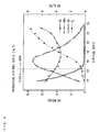
- Fig. 4 is a diagram showing examples of respective amounts (contents) of HC (hydrocarbon), NOx (nitrogen oxide), CO (carbon monoxide) and O 2 (oxygen) included in the exhaust gas of a general engine.
- the ordinate indicates the respective amounts of HC, NOx, CO and O 2 in the exhaust gas
- the abscissa indicates the air-fuel ratio (A/F) in the combustion chamber of the engine.
- “ ⁇ " indicates the amount of HC
- ⁇ indicates the amount of NOx
- ⁇ indicates the amount of CO
- ⁇ indicates the amount of O 2 .
- an amount of fuel is controlled so that the air-fuel ratio in the combustion chamber of the engine is a theoretical air-fuel ratio (A/F ⁇ 14.7) in a four-wheeled motor vehicle.
- the amounts of HC and CO in the exhaust gas tend to be less than the amount of NOx as shown in Fig. 4 .
- the air-fuel ratio of the air-fuel mixture in the combustion chamber is set on the rich side in some cases in order to increase output of the engine and obtain satisfactory drivability.
- the amounts of HC and CO increase while the amount of NOx decreases as shown in Fig. 4 . Accordingly, it is important to efficiently remove HC and CO in the exhaust gas in order to efficiently purify the exhaust gas in the motorcycle.
- the secondary air is supplied from the air cleaner box 8 to the exhaust ports 12 in the motorcycle 100 according to the present preferred embodiment.
- This secondary air promotes oxidation of HC and CO in the exhaust gas. Accordingly, HC and CO are efficiently removed. Description will now be made of characteristics of purification of the exhaust gas by the secondary air that have been discovered by the inventors.
- Fig. 5 is a diagram showing characteristics of purification of THC (total hydrocarbons) and CO by the secondary air.
- the ordinate indicates the amounts of THC and CO included in the exhaust gas
- the abscissa indicates the amount of the secondary air supplied to the exhaust ports 12.
- “a” indicates the amount of the secondary air when the air-fuel ratio of the exhaust gas is the theoretical air-fuel ratio (A/F ⁇ 14.7)
- “b” indicates the amount of the secondary air when the air-fuel ratio of the exhaust gas is 17.
- the one-dot and dash line indicates the amount of CO
- the solid line indicates the amount of THC.
- Fig. 5 shows the purification characteristics when the air-fuel ratio of the air-fuel mixture in the combustion chamber 751 ( Fig. 2 ) is set to 13.
- the amounts of THC and CO included in the exhaust gas decrease with an increase in the amount of the secondary air supplied to the exhaust ports 12, and attain respectiveminimumamounts when the air-fuel ratio of the exhaust gas reaches not less than about 17.
- CO and THC can be efficiently removed by sufficiently supplying the secondary air to the exhaust ports 12.
- CO and THC can be reliably removed by setting the air-fuel ratio of the exhaust gas to about 17.
- the inventors determined the amount of the secondary air supply to the exhaust ports 12 depending on the state of the engine 7 based on various types of simulations, experiments and other suitable methods. This enabled efficient purification of the exhaust gas of the engine 7 ( Fig. 1 ) and improvement of the combustion efficiency (output) of the engine 7. Description will now be made in detail of the appropriate amount of the secondary air supply that was discovered by the inventors based on the various types of simulations, experiments and other suitable methods.
- Figs. 6 to 8 are diagrams showing test results based on an NEDC (New European Driving Cycle) mode.
- Fig. 6 shows a result of detection of NOx in the exhaust gas
- Fig. 7 shows a result of detection of HC in the exhaust gas
- Fig. 8 shows a result of detection of CO in the exhaust gas.
- the ordinate indicates the throttle opening and the abscissa indicates the engine speed.
- the results of detection of NOx, HC and CO are indicated by " ⁇ ".
- the sizes of " ⁇ " shown in Figs. 6 to 8 are proportional to the amount of detection of each component. For example, the amount of detection of NOx is large under a condition where the diameter of " ⁇ " is large in Fig. 6 .
- the amount of NOx exhausted from the engine 7 increases as shown in Fig. 6 .
- the amount of HC exhausted from the engine 7 increases as shown in Fig. 7 .
- the amount of CO exhausted from the engine 7 does not greatly vary as shown in Fig. 8 .
- the inventors determined the amount of the secondary air supply depending on the state of the engine 7 based on the relationships shown in Figs. 6 to 8 . Details will be described below.
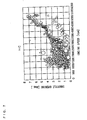
- Fig. 9 is diagram showing a relationship among the engine speed, the throttle opening, the first shut-off valve 34 and the second shut-off valve 35.
- “0" indicates that both the first shut-off valve 34 and the second shut-off valve 35 are opened
- “1” indicates that the first shut-off valve 34 is opened and the second shut-off valve 35 is closed
- "2” indicates that the first shut-off valve 34 is closed and the second shut-off valve 35 is opened
- “3” indicates that both the first shut-off valve 34 and the second shut-off valve 35 are closed.
- selection information the relationship shown in Fig. 9 is referred to as selection information.
- the selection information shown in Fig. 9 is stored in the RAM 164 (or the ROM 163) ( Fig. 2 ).
- the CPU 162 controls the first shut-off valve 34 and the second shut-off valve 35 based on the selection information shown in Fig. 9 .
- the selection information corresponding to 1600 rpm, 1800 rpm, ..., 8000 rpm and 8500 rpm as well as 0.49 deg, 0.98 deg, ..., 11.96 deg and 14.04 deg is shown in Fig. 9
- the selection information corresponding to an arbitrary engine speed and an arbitrary throttle opening is stored in the RAM 164 (or the ROM 163) in practice.
- the selection information includes data indicating that both the first shut-off valve 34 and the second shut-off valve 35 are opened when the engine speed is 1700 rpm and the throttle opening is 0.55 deg.
- the CPU 162 controls both the first shut-off valve 34 and the second shut-off valve 35 to be opened in a region where the amount of NOx exhausted from the engine 7 is small.
- the secondary air flows into the exhaust ports 12 from the first air supply pipe 72 and the second air supply pipe 73.
- the air-fuel ratio of the exhaust gas in the exhaust ports 12 and the exhaust pipe 13 is leaner than the theoretical air-fuel ratio. This promotes the oxidation of HC and CO in the exhaust gas, and HC and CO are efficiently removed.
- NOx exhausted from the engine 7 is sufficiently small, NOx can be prevented from being exhausted from the exhaust pipe 13 to the outside. As a result, the exhaust gas can be efficiently purified.
- the oxidation of HC and CO is promoted, so that the temperature of the exhaust gas increases.
- the sizes and the like of the first air supply pipe 72 and the second air supply pipe 73 are set so that the secondary air flowing from the first air supply pipe 72 and the second air supply pipe 73 into the exhaust ports 12 causes the air-fuel ratio of the exhaust gas to be about 17.
- the CPU 162 controls at least one of the first shut-off valve 34 and the second shut-off valve 35 to be closed in a region where the amount of NOx exhausted from the engine 7 is large. Thus, the amount of the secondary air supplied to the exhaust ports 12 decreases.
- both the first shut-off valve 34 and the second shut-off valve 35 are closed by the CPU 162 in a region where the engine 7 is at high load. Accordingly, supply of the secondary air to the exhaust ports 12 is stopped.
- the temperature of the exhaust gas increases. Therefore, the supply of the secondary air to the exhaust ports 12 is stopped, so that the oxidation of HC and CO in the exhaust gas is suppressed in the present preferred embodiment. Accordingly, the increase in the temperature of the exhaust gas caused by the oxidation reaction of HC and CO can be prevented. As a result, an excessive increase in the temperature of the catalyst device 13a can be prevented, and lower purification efficiency of the catalyst device 13a and degradation of the catalyst device 13a can be prevented.
- the first shut-off valve 34 and the second shut-off valve 35 are closed by the CPU 162 so that the temperature of the catalyst device 13a does not reach about 900 °C or more in the present preferred embodiment.
- the CPU 162 causes one of the first shut-off valve 34 and the second shut-off valve 35 to be opened and the amount of fuel injected by the injectors 82 to be adjusted in regions except for the high load region of the engine 7.
- the air-fuel ratio of the exhaust gas is set to the theoretical air-fuel ratio.
- the purification efficiency of the catalyst device 13a is maximized, and NOx, HC and CO in the exhaust gas can be efficiently removed.
- first shut-off valve 34 or the second shut-off valve 35 is selectively opened based on the state of the engine 7 in order to cause the air-fuel ratio of the exhaust gas to be the theoretical air-fuel ratio in the present preferred embodiment.
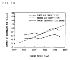
- Fig. 10 is a diagram explaining an example of the method of selecting the first shut-off valve 34 and the second shut-off valve 35.
- the ordinate indicates the amount of the secondary air
- the abscissa indicates the engine speed.
- the one-dot and dash line indicates an amount of the secondary air flowing from the first air supply pipe 72 to the exhaust ports 12
- the two-dots and dash line indicates an amount of the secondary air flowing from the second air supply pipe 73 to the exhaust ports 12.
- the dotted line indicates an amount of the secondary air (hereinafter referred to as a target secondary air amount) necessary for causing the air-fuel ratio of the exhaust gas in the exhaust ports 12 (the exhaust pipe 13) to be the theoretical air-fuel ratio in a state where the air-fuel ratio of the air-fuel mixture in the combustion chamber 751 ( Fig. 2 ) is 13.
- a target secondary air amount an amount of the secondary air necessary for causing the air-fuel ratio of the exhaust gas in the exhaust ports 12 (the exhaust pipe 13) to be the theoretical air-fuel ratio in a state where the air-fuel ratio of the air-fuel mixture in the combustion chamber 751 ( Fig. 2 ) is 13.
- a target secondary air amount an amount of the secondary air
- a difference between the amount of the secondary air flowing from the first air supply pipe 72 to the exhaust ports 12 and the target secondary air amount is smaller than a difference between the amount of the secondary air flowing from the second air supply pipe 73 to the exhaust ports 12 and the target secondary air amount in a region where the engine speed is about 2000 rpm to about 3300 rpm. Therefore, the first shut-off valve 34 is opened in the region where the engine speed is 2000 rpm to 3300 rpm.
- the difference between the amount of the secondary air flowing from the second air supply pipe 73 to the exhaust ports 12 and the target secondary air amount is smaller than the difference between the amount of the secondary air flowing from the first air supply pipe 72 to the exhaust ports 12 and the target secondary air amount in a region where the engine speed is not less than about 3300 rpm. Therefore, the second shut-off valve 35 is opened in the region where the engine speed is not less than 3300 rpm.
- the first shut-off valve 34 and the second shut-off valve 35 are selectively opened, so that the amount of the secondary air supplied to the exhaust ports 12 can be easily brought close to the target secondary air amount in the present preferred embodiment. This efficiently purifies the exhaust gas.
- the amount of fuel to be injected by the injectors 82 is adjusted by the CPU 162 in the present preferred embodiment. Specifically, the CPU 162 calculates the air-fuel ratio in the exhaust pipe 13 based on the oxygen concentration detected by the oxygen sensor 31. Then, the CPU 162 adjusts the amount of fuel to be injected by the injectors 82 based on the calculated difference between the air-fuel ratio and the theoretical air-fuel ratio.
- the first shut-off valve 34 and the second shut-off valve 35 are selectively opened so that the difference between the amount of the secondary air flowing from the first air supply pipe 72 or the second air supply pipe 73 to the exhaust ports 12 and the target secondary air amount is small in the present preferred embodiment. Accordingly, the air-fuel ratio of the exhaust gas can be easily brought close to the theoretical air-fuel ratio. In this case, since an amount of correction to the amount of injected fuel can be reduced, the output of the engine 7 can be easily stabilized. This enables comfortable driving of the motorcycle 100.
- the state of the engine 7 (the motorcycle 100) when both the first shut-off valve 34 and the second shut-off valve 35 are opened (a region where the selection information of Fig. 9 is "0") is referred to as a lean state in the following description.
- the state of the engine 7 when only the first shut-off valve 34 is opened (a region where the selection information of Fig. 9 is "1") is referred to as a first selection state.
- the state of the engine 7 when only the second shut-off valve 35 is opened (a region where the selection information of Fig. 9 is "2") is referred to as a second selection state.
- the state of the engine 7 when both the first shut-off valve 34 and the second shut-off valve 35 are closed (a region where the selection information of Fig. 9 is "3") is referred to as a third selection state.
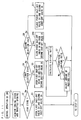
- Fig. 11 is a flowchart showing the control operation of the CPU 162.
- the CPU 162 acquires the engine speed and the throttle opening from the engine speed sensor 32 ( Fig. 2 ) and the throttle sensor 33 ( Fig. 2 ) (Step S1).
- the CPU 162 determines whether or not the current state of the engine 7 is the lean state based on the engine speed and the throttle opening acquired in Step S1 and the selection information (see Fig. 9 ) stored in the RAM 164 (Step S2).
- the CPU 162 opens the first shut-off valve 34 and the second shut-off valve 35 (Step S3). After that, the CPU 162 returns to the process of Step S1.
- Step S2 determines whether or not the current state of the engine 7 is the first selection state based on the engine speed and the throttle opening acquired in Step S1 and the selection information stored in the RAM 164 (Step S4).
- the CPU 162 opens the first shut-off valve 34 and closes the second shut-off valve 35 (Step S5).
- the CPU 162 calculates the air-fuel ratio of the exhaust gas based on the oxygen concentration detected by the oxygen sensor 31 ( Fig. 2 ) (Step S6).
- the CPU 162 subsequently determines whether or not the air-fuel ratio of the exhaust gas calculated in Step S6 is the theoretical air-fuel ratio (Step S7).
- the air-fuel ratio of the exhaust gas is the theoretical air-fuel ratio
- the CPU 162 returns to the process of Step S1 without adjusting the amount of fuel to be injected by the injectors 82.
- Step S7 When the air-fuel ratio of the exhaust gas is not the theoretical air-fuel ratio in Step S7, the CPU 162 adjusts the amount of fuel to be injected by the injectors 82 (Step S8). After that, the CPU 162 returns to the process of Step S6. The CPU 162 repeats the processes of Step S6 to Step S8 until the air-fuel ratio of the exhaust gas is determined to be the theoretical air-fuel ratio in Step S7.
- Step S4 determines whether or not the current state of the engine 7 is the second selection state based on the engine speed and the throttle opening acquired in Step S1 and the selection information stored in the RAM 164 (Step S9).
- the CPU 162 closes the first shut-off valve 34 and opens the second shut-off valve 35 (step S10). After that, the CPU 162 proceeds to the process of Step S6.
- Step S9 the CPU 162 determines that the current state of the engine 7 is the third selection state, and closes the first shut-off valve 34 and the second shut-off valve 35 (Step S11). After that, the CPU 162 returns to Step S1.
- the amount of the secondary air to be supplied to the exhaust ports 12 is adjusted based on the state of the engine 7 in the present preferred embodiment. Specifically, when the amount of NOx exhausted from the engine 7 is small, the secondary air is supplied to the exhaust ports 12 so that the air-fuel ratio of the exhaust gas is lean. This efficiently removes unburned components (HC and CO) in the exhaust gas.
- the size of the catalyst device 13a can be reduced. As a result, manufacturing cost of the motorcycle 100 can be reduced.
- the air-fuel ratio of the exhaust gas in the exhaust ports 12 is preferably set to not less than about 15.
- the amount of NOx exhausted from the engine 7 is large, the amount of the secondary air to be supplied to the exhaust ports 12 is adjusted so that the air-fuel ratio of the exhaust gas is the theoretical air-fuel ratio. Accordingly, the efficiency of purifying the exhaust gas by the catalyst device 13a can be improved.
- the first shut-off valve 34 and the second shut-off valve 35 are selectively opened, so that the amount of the secondary air supplied to the exhaust ports 12 (the exhaust pipe 13) can be easily brought close to the target secondary air amount.
- the amount of correction to the amount of injected fuel necessary for causing the air-fuel ratio of the exhaust gas to be the theoretical air-fuel ratio can be reduced. This stabilizes the output of the engine 7, improves drivability of the motorcycle 100 and improves fuel efficiency.
- the secondary air is supplied from the passages 721 to 724 under a condition where an amount of an internal EGR (Internal Exhaust Gas Recirculation) is large, that is, when the engine 7 is at low speed and low load.
- EGR Internal Exhaust Gas Recirculation
- the passages 721 to 724 are connected to the vicinity of the open ends 12a, respectively, thus allowing the secondary air to flow into the combustion chamber 751. This stabilizes the combustion of the air-fuel mixture in the combustion chamber 751.
- the first shut-off valve 34 can be closed and the second shut-off valve 35 can be opened for preventing the secondary air from flowing into the combustion chamber 751.
- the first shut-off valve 34 is closed and the second shut-off valve 35 is opened under a predetermined condition.
- the oxidation reaction of the unburned components in the exhaust gas can be promoted while the increase in the temperature of the exhaust gas in the vicinity of the combustion chamber 751 can be prevented.
- This sufficiently purifies the exhaust gas and prevents heat transfer from the exhaust gas to the cylinder head 75. As a result, since the increase in the temperature of the cylinder head 75 can be prevented, degradation of the cylinder head 75 can be prevented.
- the second air supply pipe 73 is arranged on the front side of the cylinder head 75.
- heat of the second air supply pipe 73 and heat of the exhaust gas in the second air supply pipe 73 can be efficiently released from a front surface of the cylinder head 75. This prevents the increase in the temperature of the second air supply pipe 73 and the cylinder head 75. As a result, degradation of the second air supply pipe 73 and the cylinder head 75 can be reliably prevented.
- the air-fuel ratio of the exhaust gas is calculated by the CPU 162 based on the detected value of the oxygen sensor 31 in the above-described preferred embodiments
- the air-fuel ratio of the exhaust gas may be calculated based on the amount of fuel injected by the injectors 82 and the amount of air taken into the combustion chamber 751. Note that the amount of the air taken into the combustion chamber 751 can be detected by providing intake air pressure sensors in the intake ports 9.
- the state of the engine 7 is determined based on the engine speed and the throttle opening in the above-described preferred embodiments, the method of determining the state of the engine 7 is not limited to the above-described examples.
- pressure sensors may be provided in the intake ports 9, and the CPU 162 may determine the state of the engine 7 based on the pressure (negative pressure) in the intake ports 9 detected by the pressure sensors and the engine speed.
- NOx sensors may be provided in the exhaust ports 12 or the exhaust pipe 13, and the CPU 162 may determine the state of the engine 7 based on the amount of NOx detected by the NOx sensors, for example.
- temperature sensors may be provided in the vicinity of the open ends 12a of the exhaust ports 12, and the CPU 162 may determine the state of the engine 7 based on the temperature of the exhaust gas detected by the temperature sensors, for example.
- first air supply pipe 72 and the second air supply pipe 73 are connected to the exhaust ports 12 in the above-described preferred embodiments, one or both of the first air supply pipe 72 and the second air supply pipe 73 may be connected to the exhaust pipe 13.
- throttle valves 81 are electrically opened/closed by the CPU 162 in the above-described preferred embodiments, the throttle valves 81 may be mechanically opened/closed.
- the oxygen sensor 31 may be provided in each cylinder 74.
- the oxygen sensor 31 may be provided in each of the passages 131 to 134.
- the engine 7 is not limited to the four-cylinder engine.
- a two-cylinder engine, a six-cylinder engine, an eight-cylinder engine and the like may be used.
- the engine 7 may be a single-cylinder engine.
- the air-fuel ratio of the exhaust gas is preferably corrected by adjusting the amount of fuel injected by the injectors 82 in the above-described preferred embodiments, the air-fuel ratio of the exhaust gas may be corrected by adjusting the throttle opening or adjusting the throttle opening and the amount of injected fuel.
- the air cleaner box 8 is preferably used as the supply source of the secondary air in the above-described preferred embodiments, the supply source of the secondary air is not limited to the air cleaner box 8.
- the throttle body 10 may be used as the supply source of the secondary air, for example.
- the secondary air supply system 1000 may be provided in another vehicle such as a three wheeled vehicle or a four wheeled vehicle.
- the opening/closing of the first shut-off valve 34 and the second shut-off valve 35 preferably has hysteresis characteristics. In this case, unnecessary opening/closing of the first shut-off valve 34 and the second shut-off valve 35 can be prevented. This prevents degradation of the first shut-off valve 34 and the second shut-off valve 35.
- the secondary air may be supplied so that the air-fuel ratio of the exhaust gas is not on the rich side (insufficient oxygen).
- the unburned components (HC and CO) in the exhaust gas can be prevented from being exhausted to the outside.
- the sizes of the first air supply pipe 72 and the second air supply pipe 73, the positions where the check valves 36, 37 are arranged and so on are determined so that the air fuel ratio of the exhaust gas in the exhaust ports 12 and the exhaust pipe 13 and the air-fuel ratio of the air-fuel mixture in the combustion chamber 751 can be set to respective desired values.
- the above-mentioned sizes and the like are determined so that the first shut-off valve 34 and the second shut-off valve 35 are opened in the state where the air-fuel ratio of the air-fuel mixture is set to 13 to cause the air-fuel ratio of the exhaust gas to be 17.
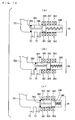
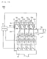
- Fig. 12 is a schematic view showing a secondary air supply system 1001 according to a second preferred embodiment of the present invention.
- the secondary air supply system 1001 according to the second preferred embodiment is different from the secondary air supply system 1000 of Fig. 3 in the following points.
- a first common pipe 701, the first air supply pipe 72 and the second air supply pipe 73 are provided as a secondary air supply path from the air cleaner box 8 to the exhaust ports 12 in the present preferred embodiment.
- One end of the first common pipe 701 is connected to the air cleaner box 8, and the other end of the first common pipe 701 is connected to a third shut-off valve 38. Respective one ends of the first air supply pipe 72 and the second air supply pipe 73 are connected to the third shut-off valve 38.
- the secondary air flowing from the air cleaner box 8 into the first common pipe 701 is supplied to the exhaust ports 12 through one or both of the first air supply pipe 72 and the second air supply pipe 73.
- Fig. 13 is a diagram explaining an example of the configuration of the third shut-off valve 38.
- Fig. 13 (a) shows a state of the third shut-off valve 38 when shutting off the flow of the secondary air from the first common pipe 701 to the first and second air supply pipes 72, 73.
- Fig. 13 (b) shows a state of the third shut-off valve 38 when allowing the flow of the secondary air from the first common pipe 701 to the first air supply pipe 72 and shutting off the flow of the secondary air from the first common pipe 701 to the second air supply pipe 73.
- Fig. 13 (c) shows a state of the third shut-off valve 38 when allowing the flow of the secondary air from the first common pipe 701 to the first and second air supply pipes 72, 73.
- the third shut-off valve 38 includes a cylinder 380, first magnetic coils 381, second magnetic coils 382, third magnetic coils 383, a valve rod 384, a shut-off plate 385 and a core 386.
- the first common pipe 701 is connected to one end of the cylinder 380, and the first air supply pipe 72 and the second air supply pipe 73 are connected to an outer periphery of the cylinder 380 on the one end side.
- the first to third magnetic coils 381 to 383 are provided at an outer peripheral surface of the cylinder 380.
- the valve rod 384 is accommodated within the cylinder 380.
- the shut-off plate 385 having a disk shape is provided at one end of the valve rod 384.
- the shut-off plate 385 is provided so as to slide along an inner peripheral surface of the cylinder 380.
- the core 386 is provided at the other end of the valve rod 384.
- the first magnetic coils 381 to the third magnetic coils 383 are selectively energized by the CPU 162 ( Fig. 2 ), so that an electromagnetic force is generated.
- This causes the core 386 to move to any position in the cylinder 380 of an inward position ( Fig. 13 (a) ) of the first magnetic coils 381, an inward position ( Fig. 13 (b) ) of the second magnetic coils 382, and an inward position ( Fig. 13 (c) ) of the third magnetic coils 383.
- the shut-off plate 385 moves to any position of a position ( Fig. 13 (a) ) in which the shut-off plate 385 shuts off the flow of the secondary air from the first common pipe 701 to the first and second air supply pipes 72, 73, a position ( Fig. 13 (b) ) in which the shut-off plate 385 allows the flow of the secondary air from the first common pipe 701 to the first air supply pipe 72 and shuts off the flow of the secondary air from the first common pipe 701 to the second air supply pipe 73, and a position ( Fig. 13 (c) ) in which the shut-off plate 385 allows the flow of the secondary air from the first common pipe 701 to the first and second air supply pipes 72, 73.
- the amount of the secondary air to be supplied to the exhaust ports 12 can be adjusted by the third shut-off valve 38 in the present preferred embodiment.
- the secondary air supply system 1001 can be made low in cost.
- positions of a connection portion (hereinafter referred to as a first connection portion) of the first air supply pipe 72 and the cylinder 380 and a connection portion (hereinafter referred to as a second connection portion) of the second air supply pipe 73 and the cylinder 380 are not limited to the examples of Fig. 13 .
- the first connection portion and the second connection portion may be provided in positions opposite to those of Fig. 13 .
- Fig. 14 is a schematic view showing a secondary air supply system 1002 according to a third preferred embodiment.
- the secondary air supply system 1002 according to the third preferred embodiment is different from the secondary air supply system 1000 of Fig. 3 in the following points.
- the first air supply pipe 72, the second air-supply pipe 73 and four second common pipes 702 are provided as the secondary air supply path from the air cleaner box 8 to the exhaust ports 12 in the present preferred embodiment.
- Respective one ends of the passages 721 and 731 are connected to a common check valve 391
- respective one ends of the passages 722 and 732 are connected to a common check valve 391
- respective one ends of the passages 723 and 733 are connected to a common check valve 391
- respective one ends of the passages 724 and 734 are connected to a common check valve 391.
- One ends of the second common pipes 702 are connected to the check valves 391, respectively.
- the other ends of the second common pipes 702 are connected to the exhaust ports 12, respectively.
- the secondary air flowing from the air cleaner box 8 to the first air supply pipe 72 and the second air supply pipe 73 joins at the check valve 391 and is then supplied to the exhaust ports 12 through the second common pipes 702.
- the configuration of the secondary air supply system 1002 can be simplified because a plurality of supply pipes for supplying the secondary air to the exhaust ports 12 are not required to be connected to the exhaust ports 12.
- the second common pipes 702 may be connected to the exhaust ports 12, or may be connected to the exhaust pipe 13. Moreover, the second common pipes 702 may be connected to the vicinity of the open ends 12a, or may be connected to positions away from the open ends 12a.
- Fig. 15 is schematic view showing a secondary air supply system 1003 according to a fourth preferred embodiment.
- the secondary air supply system 1003 according to the fourth preferred embodiment is different from the secondary air supply system 1001 of Fig. 12 in the following points.
- the first common pipe 701, the first air supply pipe 72, the second air supply pipe 73 and the four second common pipes 702 are provided as the secondary air supply path from the air cleaner box 8 to the exhaust ports 12 in the present preferred embodiment.
- the respective one ends of the passages 721 and 731 are connected to the common check valve 391
- the respective one ends of the passages 722 and 732 are connected to the common check valve 391
- the respective one ends of the passages 723 and 733 are connected to the common check valve 391
- the respective one ends of the passages 724 and 734 are connected to the common check valve 391.
- the one ends of the second common pipes 702 are connected to the check valves 391, respectively.
- the other ends of the second common pipes 702 are connected to the exhaust ports 12, respectively.
- the amount of the secondary air to be supplied to the exhaust ports 12 can be adjusted by the third shut-off valve 38.
- the secondary air supply system 1003 can be made low in cost because it is not necessary to provide the plurality of valves for adjusting the amount of the secondary air.
- the secondary air flowing from the air cleaner box 8 to the first air supply pipe 72 and the second air supply pipe 73 joins at the check valve 391 and is then supplied to the exhaust ports 12 through the second common pipes 702.
- the configuration of the secondary air supply system 1003 can be simplified because the plurality of supply pipes for supplying the secondary air to the exhaust ports 12 are not required to be connected to the exhaust ports 12.
- the exhaust port 12 and the exhaust pipe 13 are examples of an exhaust passage
- the air cleaner box 8 or the throttle body 10 is an example of a supply source
- the first air supply pipe 72 and the second air supply pipe 73 are examples of first and second paths
- the CPU 162 is an example of a determiner
- the first shut-off valve 34 and the second shut-off valve 35 or the third shut-off valve 38 are examples of a path switching device
- the lean state is an example of a first state
- the first selection state and the second selection state are examples of a second state
- the third selection state is an example of a third state
- the ROM 163 or the RAM 164 is an example of a storage
- the NOx sensor is an example of a first detector
- the injector 82 is an example of a fuel supply device
- the oxygen sensor 31 is an example of a second detector
- the rear wheel 18 is an example of a drive wheel
- the rear wheel driven sprocket 19 and the chain 20 are examples of a transmission mechanism.
Landscapes
- Engineering & Computer Science (AREA)
- Chemical & Material Sciences (AREA)
- Chemical Kinetics & Catalysis (AREA)
- Health & Medical Sciences (AREA)
- Toxicology (AREA)
- Combustion & Propulsion (AREA)
- Mechanical Engineering (AREA)
- General Engineering & Computer Science (AREA)
- Exhaust Gas After Treatment (AREA)
- Electrical Control Of Air Or Fuel Supplied To Internal-Combustion Engine (AREA)
Abstract
Description
- The present invention relates to a secondary air supply system that supplies secondary air to an engine and a vehicle including the same.
- Conventionally, a technique for supplying secondary air to an exhaust pipe has been developed in order to purify an exhaust gas exhausted from a vehicle (see
JP 2006-183513 A - In a secondary air introduction device described in
JP 2006-183513 A - In a vehicle such as a motorcycle, purification of the exhaust gas using a catalyst device is performed in addition to the purification of the exhaust gas using the secondary air. When an amount of the secondary air supplied to the exhaust pipe increases, however, an amount of oxygen flowing into the catalyst device increases, resulting in lower purification efficiency of the catalyst device. Therefore, it is difficult to effectively improve the efficiency of purifying the exhaust gas simply by providing the foregoing secondary air introduction device and catalyst device in the exhaust pipe.
- In order to overcome the problems described above, preferred embodiments of the present invention provide a secondary air supply system capable of effectively improving efficiency of purifying an exhaust gas and a vehicle including the same.
- (1) According to an aspect of the present invention, a secondary air supply system that supplies secondary air to an exhaust passage of an engine includes a supply source of the secondary air, first and second paths through which the secondary air is supplied from the supply source to the exhaust passage, a determiner that determines a state of the engine, and a path switching device that selectively switches the first and second paths to a communicated state or a shut-off state, respectively, based on the state of the engine determined by the determiner.
According to this secondary air supply system, the secondary air is supplied to the exhaust passage from the supply source through the first and second paths. This promotes oxidation reaction of unburned components included in the exhaust gas of the engine. As a result, the unburned components included in the exhaust gas are removed.
Here, purification by the secondary air and purification by a catalyst device must be appropriately combined in order to efficiently purify the exhaust gas. That is, when the secondary air is supplied to the exhaust passage so that the air-fuel ratio in the exhaust passage is lean, the unburned components (HC and CO) in the exhaust gas can be efficiently removed, but the efficiency of purifying nitrogen oxide (NOx) by the catalyst device is reduced. In addition, when the secondary air is supplied to the exhaust passage so that the air-fuel ratio in the exhaust passage is a theoretical air-fuel ratio, the efficiency of purifying the exhaust gas by the catalyst device is improved, but the amount of the unburned components removed by the secondary air decreases.
Therefore, the first and second paths are selectively switched to the communicated state or the shut-off state, respectively, by the path switching device based on the state of the engine determined by the determiner in this secondary air supply system.
In this case, when the state of the engine is a state where the amount of the unburned components removed by the secondary air should be increased, the first and second paths are brought into the communicated state to allow the amount of secondary air supply to increase. This sufficiently promotes the oxidation reaction of the unburned components in the exhaust gas. As a result, the unburned components in the exhaust gas are efficiently removed.
When the state of the engine is a state where the efficiency of purifying the exhaust gas by the catalyst device should be improved, at least one of the first and second paths is brought into the shut-off state to allow the amount of the secondary air supply to decrease. This causes the air-fuel ratio in the exhaust passage to be close to the theoretical air-fuel ratio, so that the efficiency of purifying the exhaust gas by the catalyst device is improved.
As described above, the amount of the secondary air to be supplied to the exhaust passage can be appropriately adjusted based on the state of the engine determined by the determiner according to this secondary air supply system. Thus, the purification of the exhaust gas by the secondary air and the purification of the exhaust gas by the catalyst device can be appropriately combined. As a result, the efficiency of purifying the exhaust gas can be effectively improved. - (2) The state of the engine may include a first state and a second state set in advance based on an amount of nitrogen oxide exhausted from a combustion chamber of the engine, and the amount of the nitrogen oxide in the first state may be smaller than the amount of the nitrogen oxide in the second state, and the path switching device may bring the first and second paths into the communicated state when the state of the engine is determined to be the first state by the determiner, and bring either one of the first and second paths into the communicated state when the state of the engine is determined to be the second state by the determiner.
According to this secondary air supply system, when the state of the engine is the first state, that is, when the amount of the nitrogen oxide exhausted from the combustion chamber is small, the first and second paths are brought into the communicated state by the path switching device. In this case, since a sufficient amount of secondary air is supplied to the exhaust passage, the unburned components included in the exhaust gas can be efficiently removed. In addition, since the amount of the nitrogen oxide included in the exhaust gas is small, the nitrogen oxide can be sufficiently prevented from being exhausted to the outside even though the purification efficiency of the catalyst device is decreased.
Moreover, when the state of the engine is the second state, that is, when the amount of the nitrogen oxide exhausted from the combustion chamber is large, either one of the first and second paths is brought into the communicated state by the path switching device. In this case, the amount of the secondary air supplied to the exhaust passage decreases, and the air-fuel ratio in the exhaust passage is close to the theoretical air-fuel ratio. This improves the purification efficiency of the catalyst device, so that the nitrogen oxide included in the exhaust gas can be reliably removed.
As a result of these, the efficiency of purifying the exhaust gas can be sufficiently improved. - (3) The secondary air supply system may further include a throttle valve that adjusts an intake air amount of the engine, wherein the determiner may determine the first state and the second state based on a rotational speed of the engine and an opening of the throttle valve.
In this case, the first and second states can be easily determined based on the rotational speed of the engine and the opening of the throttle valve. This easily improves the efficiency of purifying the exhaust gas. - (4) The secondary air supply system may further include a storage that stores information indicating a relationship among the rotational speed of the engine, the opening of the throttle valve, the first state and the second state.
In this case, the first state and the second state can be reliably determined based on the information stored in the storage. This reliably improves the efficiency of purifying the exhaust gas. - (5) The determiner may determine the first state and the second state based on a rotational speed of the engine and a pressure in an intake port of the engine. In this case, the first state and the second state can be easily determined. This easily improves the efficiency of purifying the exhaust gas.
- (6) The secondary air supply system may further include a first detector that detects the amount of the nitrogen oxide exhausted from the combustion chamber of the engine, wherein the determiner may determine the first state and the second state based on the amount of the nitrogen oxide detected by the first detector.
In this case, the first state and the second state can be reliably determined based on the result of detection by the first detector. This reliably improves the efficiency of purifying the exhaust gas. - (7) The state of the engine may further include a third state set in advance based on a load applied on the engine, the load in the third state is higher than a load in the first state and the second state, and the path switching device may bring the first and second paths into the shut-off state when the state of the engine is determined to be the third state by the determiner.
When the state of the engine is a high load state, the temperature of the exhaust gas increases. Therefore, when the state of the engine is the third state, that is, the high load state, the first and second paths are brought into the shut-off state by the path switching device in this secondary air supply system. This causes supply of the secondary air to the exhaust passage to be shut off, so that the oxidation of the unburned components in the exhaust gas is suppressed.
In this case, since the increase in the temperature of the exhaust gas due to the oxidation reaction of the unburned components is prevented, the excessive increase in the temperature of the exhaust gas is prevented. Thus, the excessive increase in the temperature of the catalyst device is prevented even when the engine is in the high load state. As a result, lower purification efficiency of the catalyst device and degradation of the catalyst device are prevented. - (8) The secondary air supply system may further include a fuel supply device that supplies fuel to the engine so that the air-fuel ratio in the combustion chamber of the engine is a predetermined value, and a second detector that detects oxygen concentration in the exhaust passage, wherein the fuel supply device may correct, when the engine is determined to be in the second state by the determiner, an amount of the fuel supplied to the engine based on the oxygen concentration detected by the second detector so that the air-fuel ratio in the exhaust passage is a substantially theoretical air-fuel ratio.
When the state of the engine is the second state, the amount of fuel to be supplied to the engine is corrected based on the oxygen concentration detected by the second detector in this secondary air supply system. This causes the air-fuel ratio in the exhaust passage to be set to the substantially theoretical air-fuel ratio, so that the purification efficiency of the catalyst device is reliably improved. - (9) The path switching device may bring, when the state of the engine is determined to be the second state by the determiner, either one of the first and second paths into the communicated state so that an amount of the correction by the fuel supply device is reduced.
In this case, since the amount of the correction to the amount of fuel to be supplied by the fuel supply device can be reduced, the fuel supplied to the engine can be less increased/decreased. This stabilizes output of the engine, improves drivability of the vehicle and improves fuel efficiency. - (10) At least one of the first and second paths may be connected to the exhaust passage at a position within 50 mm from the combustion chamber of the engine.
In this case, at least one of the first and second paths is arranged in the vicinity of the combustion chamber, thus allowing a portion of the secondary air supplied from the first or second path to the exhaust passage to flow into the combustion chamber. This stabilizes combustion of an air-fuel mixture in the combustion chamber and stabilizes the output of the engine. - (11) The air-fuel ratio in the exhaust passage may be set to not less than 15 by the secondary air supplied through the first and second paths.
In this case, the first and second paths are brought into the communicated state, so that the air-fuel ratio in the exhaust passage is set to not less than 15. This reliably promotes the oxidation reaction of the unburned components in the exhaust gas. As a result, the unburned components in the exhaust gas can be more reliably removed. - (12) According to another aspect of the present invention, a vehicle includes an engine, a drive wheel, a transmission mechanism that transmits power generated by the engine to the drive wheel, an exhaust passage through which an exhaust gas exhausted from the engine flows, a catalyst device that is provided in the exhaust passage and purifies the exhaust gas exhausted from the engine, and a secondary air supply system that supplies secondary air to the exhaust passage, wherein the secondary air supply system includes a supply source of the secondary air, first and second paths through which the secondary air is supplied from the supply source to the exhaust passage, a determiner that determines a state of the engine, and a path switching device that selectively switches the first and second paths to a communicated state or a shut-off state, respectively, based on the state of the engine determined by the determiner.
- In this vehicle, the power generated by the engine is transmitted to the drive wheel through the transmission mechanism. This causes the vehicle to drive. In addition, the exhaust gas exhausted from the engine is purified by the catalyst device provided in the exhaust passage.
- Moreover, the secondary air is supplied from the supply source to the exhaust passage through the first and second paths according to the secondary air supply system of this vehicle. This promotes oxidation reaction of unburned components included in the exhaust gas of the engine. As a result, the unburned components included in the exhaust gas are removed.
- Here, purification by the secondary air and purification by the catalyst device must be appropriately combined in order to efficiently purify the exhaust gas. That is, when the secondary air is supplied to the exhaust passage so that the air-fuel ratio in the exhaust passage is lean, the unburned components (HC and CO) in the exhaust gas can be efficiently removed, but the efficiency of purifying the nitrogen oxide (NOx) by the catalyst device is reduced. In addition, when the secondary air is supplied to the exhaust passage so that the air-fuel ratio in the exhaust passage is a theoretical air-fuel ratio, the efficiency of purifying the exhaust gas by the catalyst device is improved, but the amount of the unburned components removed by the secondary air decreases.
- Therefore, the first and second paths are selectively switched to the communicated state or the shut-off state, respectively, by the path switching device based on the state of the engine determined by the determiner in this secondary air supply system.
- In this case, when the state of the engine is a state where the amount of the unburned components removed by the secondary air should be increased, the first and second paths are brought into the communicated state to allow the amount of secondary air supply to increase. Thissufficiently promotes the oxidation reaction of the unburned components in the exhaust gas. As a result, the unburned components in the exhaust gas are efficiently removed.
- When the state of the engine is a state where the efficiency of purifying the exhaust gas by the catalyst device should be improved, at least one of the first and second paths is brought into the shut-off state to allow the amount of the secondary air supply to decrease. This causes the air-fuel ratio in the exhaust passage to be close to the theoretical air-fuel ratio, so that the efficiency of purifying the exhaust gas by the catalyst device is improved.
- As described above, the amount of the secondary air to be supplied to the exhaust passage can be appropriately adjusted based on the state of the engine determined by the determiner according to this secondary air supply system. Thus, the purification of the exhaust gas by the secondary air and the purification of the exhaust gas by the catalyst device can be appropriately combined. As a result, the efficiency of purifying the exhaust gas can be effectively improved.
- According to the present invention, an appropriate amount of secondary air depending on the state of the engine is supplied to the exhaust passage. Thus, the purification of the exhaust gas by the secondary air and the purification of the exhaust gas by the catalyst device can be appropriately combined. As a result, the efficiency of purifying the exhaust gas can be effectively improved.
- Other features, elements, characteristics, and advantages of the present invention will become more apparent from the following description of preferred embodiments of the present invention with reference to the attached drawings.
-
-
Fig. 1 is an external side view showing a motorcycle including a secondary air supply system according to a first -
Fig. 2 is a schematic view showing the secondary air supply system. -
Fig. 3 is a schematic view showing the secondary air supply system. -
Fig. 4 is a diagram showing examples of respective amounts of HC, NOx, CO and O2 included in an exhaust gas. -
Fig. 5 is a diagram showing characteristics of purification of THC and CO by secondary air. -
Fig. 6 is a diagram showing a test result based on an NEDC mode. -
Fig. 7 is a diagram showing a test result based on the NEDC mode. -
Fig. 8 is a diagram showing a test result based on the NEDC mode. -
Fig. 9 is diagram showing a relationship among an engine speed, a throttle opening, a first shut-off valve and a second shut-off valve. -
Fig. 10 is a diagram explaining an example of a method of selecting the first shut-off valve and the second shut-off valve. -
Fig. 11 is a flowchart showing a control operation of a CPU. -
Fig. 12 is a schematic view showing a secondary air supply system according to a second preferred embodiment. -
Fig. 13 is a diagram explaining an example of the configuration of a third shut-off valve. -
Fig. 14 is a schematic view showing a secondary air supply system according to a third preferred embodiment. -
Fig. 15 is schematic view showing a secondary air supply system according to a fourth preferred embodiment. - Hereinafter, description is made of a secondary air supply system and a vehicle including the same according to preferred embodiments of the present invention while referring to the drawings. Note that description is made of a motorcycle as an example of the vehicle in the following description.
-
Fig. 1 is an external side view showing the motorcycle including the secondary air supply system according to a first preferred embodiment of the present invention. - As shown in
Fig. 1 , themotorcycle 100 includes amain frame 1. Themain frame 1 is provided with ahead pipe 2 at its front end. Thehead pipe 2 is provided with afront fork 3 that can turn. Afront wheel 4 is rotatably supported at a lower end of thefront fork 3. Ahandle 5 is attached to an upper end of thehead pipe 2. - A
cowling 6 is arranged so as to cover a front and sides of themain frame 1. Anengine 7 is provided at the approximate center of themain frame 1. An aircleaner box 8 is provided above theengine 7. Athrottle body 10 is arranged so as to connect theair cleaner box 8 and anintake port 9 of theengine 7. - An
intake passage 11 that communicates the inside of theair cleaner box 8 and the outside is arranged so as to be covered with thecowling 6 at the front of themotorcycle 100. An end of theintake passage 11 opens at a front surface of thecowling 6. Thus, outside air is taken into theengine 7 through theintake passage 11, theair cleaner box 8, thethrottle body 10 and theintake port 9. - An end of an
exhaust pipe 13 is connected to anexhaust port 12 of theengine 7. Acatalyst device 13a for purifying an exhaust gas exhausted from theengine 7 is inserted in theexhaust pipe 13. Thecatalyst device 13a is composed of a three-way catalyst, for example. Amuffler device 14 is connected to the other end of theexhaust pipe 13. The exhaust gas in theengine 7 is exhausted to the outside through theexhaust port 12, theexhaust pipe 13 and themuffler device 14. - A
seat 15 is provided above theengine 7. An ECU (Electronic Control Unit) 16 that controls operations of each component of themotorcycle 100 is provided below theseat 15. Details of theECU 16 will be described below. - A
rear arm 17 is connected to themain frame 1 so as to extend toward the back of theengine 7. Therear arm 17 holds arear wheel 18 and a rear wheel drivensprocket 19 in a rotatable manner. A torque of acrankshaft 71 of theengine 7 is transmitted to the rear wheel drivensprocket 19 through a transmission (not shown) and achain 20. This causes therear wheel 18 to rotate. - A first
air supply pipe 72 and a secondair supply pipe 73 are provided at the approximate center of the main frame - 1. One end of the first
air supply pipe 72 is connected to theexhaust port 12, and the other end thereof is connected to theair cleaner box 8. Similarly, one end of the secondair supply pipe 73 is connected to theexhaust port 12, and the other end thereof is connected to theair cleaner box 8. Details of the first and secondair supply pipes -
Figs. 2 and3 are schematic views showing the secondary air supply system according to the present preferred embodiment. Note thatFig. 2 shows a vertical sectional view of theengine 7, andFig. 3 shows a top view of theengine 7. - As shown in
Figs. 2 and3 , the secondaryair supply system 1000 according to the present preferred embodiment includes theengine 7, theECU 16, anaccelerator opening sensor 30, anoxygen sensor 31, anengine speed sensor 32, athrottle sensor 33, a first shut-offvalve 34, a second shut-offvalve 35, athrottle valve 81 and aninjector 82. - As shown in
Fig. 2 , theengine 7 includes acylinder 74 and acylinder head 75. Apiston 76 is arranged so as to move up and down in thecylinder 74. Thepiston 76 is coupled to thecrankshaft 71 by a connecting rod and a crank (not shown). - A
combustion chamber 751 for burning an air-fuel mixture is formed in thecylinder head 75. Theintake port 9 and theexhaust port 12 are formed in thecylinder head 75 so as to communicate thecombustion chamber 751 and the outside of thecylinder head 75. - An
intake valve 77 is provided at a downstreamopen end 9a of theintake port 9, and anexhaust valve 78 is provided at an upstreamopen end 12a of theexhaust port 12. An intakevalve driving device 79 for driving theintake valve 77 and an exhaustvalve driving device 80 for driving theexhaust valve 78 are provided in thecylinder head 75. Note that one cam of the intakevalve driving device 79 and one cam of the exhaustvalve driving device 80 are shown inFig. 2 . Thethrottle valve 81 and theinjector 82 are provided in thethrottle body 10. - As shown in
Fig. 3 , theengine 7 includes fourcylinders 74. Theintake port 9, theexhaust port 12, thethrottle valve 81, and the injector 82 (seeFig. 2 ) are provided for eachcylinder 74. Each of theintake ports 9 on thecylinder 74 side branches into two passages. Similarly, each of theexhaust ports 12 on thecylinder 74 side branches into two passages. Thus, each of theintake ports 9 has twoopen ends 9a, and each of theexhaust ports 12 has twoopen ends 12a. Twointake valves 77 and twoexhaust valves 78 ofFig. 2 are provided for eachcylinder 74. - As shown in
Fig. 3 , theexhaust pipe 13 on the upstream side branches into fourpassages 131 to 134. Thepassages 131 to 134 are connected to theexhaust ports 12, respectively. One ends of the firstair supply pipe 72 and the secondair supply pipe 73 are connected to theair cleaner box 8, respectively. The other end of the firstair supply pipe 72 branches into fourpassages 721 to 724. Similarly, the other end of the secondair supply pipe 73 branches into fourpassages 731 to 734. - The
passages 721 to 724 are connected to the vicinity of one open ends 12a of theexhaust ports 12, respectively, and thepassages 731 to 734 are connected to theexhaust ports 12 on theexhaust pipe 13 side, respectively. Note that thepassages 721 to 724 are preferably connected to theexhaust ports 12, respectively, at positions within 50 mm from the open ends 12a. Thepassages 731 to 734 are preferably connected to theexhaust ports 12, respectively, at positions of not less than 50 mm away from the connection portions of thepassages 721 to 724 and theexhaust ports 12. - In the present preferred embodiment, air in the
air cleaner box 8 is supplied to theexhaust ports 12 through the firstair supply pipe 72 and the secondair supply pipe 73. Note that the air supplied from theair cleaner box 8 to theexhaust ports 12 is referred to as secondary air in the following description. - A
check valve 36 is provided in each of thepassages 721 to 724 and acheck valve 37 is provided in each of thepassages 731 to 734. This prevents backflow of the exhaust gas from theexhaust ports 12 to theair cleaner box 8. In addition, the first shut-offvalve 34 is provided upstream of thepassages 721 to 724 in the firstair supply pipe 72, and the second shut-offvalve 35 is provided upstream of thepassages 731 to 734 in the secondair supply pipe 73. - The accelerator opening sensor 30 (
Fig. 2 ) is positioned in the vicinity of thethrottle valve 81 of thethrottle body 10, and detects an operation amount (hereinafter referred to as an accelerator opening) of an accelerator grip (not shown) by a driver. Theoxygen sensor 31 is provided in theexhaust pipe 13, and detects the oxygen concentration in theexhaust pipe 13. As shown inFig. 3 , theoxygen sensor 31 is provided between thepassages 131 to 134 and thecatalyst device 13a. - The engine speed sensor 32 (
Figs. 2 and3 ) detects a rotational speed (hereinafter referred to as an engine speed) of the engine 7 (the crankshaft 71). Thethrottle sensor 33 detects the opening of the throttle valves 81 (hereinafter referred to as a throttle opening). - The
ECU 16 preferably includes an I/F (interface) 161, a CPU (Central Processing Unit) 162, a ROM (Read On Memory) 163 and a RAM (Random Access Memory) 164, for example. - The accelerator opening detected by the accelerator opening sensor 30 (
Fig. 2 ), the oxygen concentration detected by theoxygen sensor 31, the engine speed detected by theengine speed sensor 32 and the throttle opening detected by thethrottle sensor 33 are supplied to theCPU 162 through the I/F 161. A control program of theCPU 162 is stored in theROM 163. Various kinds of data related to the secondaryair supply system 1000 are stored in theRAM 164. Moreover, theRAM 164 functions as a processing area of theCPU 162. - The
CPU 162 controls opening/closing of thethrottle valves 81 based on a detected value of theaccelerator opening sensor 30. Note that data indicating a relationship between the accelerator opening and the throttle opening is stored in theRAM 164 in the present preferred embodiment. TheCPU 162 controls thethrottle valves 81 based on the detected value of theaccelerator opening sensor 30 and the data stored in theRAM 164. - In the present preferred embodiment, the accelerator grip (not shown) and the
throttle valves 81 are mechanically coupled to one another. In this case, since the opening/closing of thethrottle valves 81 can be mechanically restricted, an upper limit value of the throttle opening depending on an operation amount of the accelerator grip can be set, for example. - Moreover, the
CPU 162 adjusts an air-fuel ratio of the air-fuel mixture in thecombustion chamber 751 by controlling theinjectors 82. In the present preferred embodiment, the air-fuel ratio of the air-fuel mixture in thecombustion chamber 751 is set on a rich side by theCPU 162, for example. - Furthermore, the
CPU 162 controls opening/closing of each of the first shut-offvalve 34 and the second shut-offvalve 35 based on the detected values of theengine speed sensor 32 and thethrottle sensor 33. Accordingly, the amount of the secondary air supplied from theair cleaner box 8 to theexhaust ports 12 is adjusted. - In the present preferred embodiment, information indicating a relationship among the engine speed, the throttle opening, an opening/closing state of the first shut-off
valve 34 and an opening/closing state of the second shut-offvalve 35 is stored in theRAM 164. TheCPU 162 controls the first shut-offvalve 34 and the second shut-offvalve 35 based on the detected value of theengine speed sensor 32, the detected value of thethrottle sensor 33, and the information stored in theRAM 164. In addition, theCPU 162 corrects an amount of fuel injected by theinjectors 82 based on the detected value of theoxygen sensor 31. Details of the control operation of theCPU 162 will be described below. -
Fig. 4 is a diagram showing examples of respective amounts (contents) of HC (hydrocarbon), NOx (nitrogen oxide), CO (carbon monoxide) and O2 (oxygen) included in the exhaust gas of a general engine. Note that inFig. 4 , the ordinate indicates the respective amounts of HC, NOx, CO and O2 in the exhaust gas, and the abscissa indicates the air-fuel ratio (A/F) in the combustion chamber of the engine. InFig. 4 , "Δ" indicates the amount of HC, "◇" indicates the amount of NOx, "○"indicates the amount of CO, and "●" indicates the amount of O2. - Generally, an amount of fuel is controlled so that the air-fuel ratio in the combustion chamber of the engine is a theoretical air-fuel ratio (A/F ≒ 14.7) in a four-wheeled motor vehicle. In this case, the amounts of HC and CO in the exhaust gas tend to be less than the amount of NOx as shown in
Fig. 4 . - On the other hand, in a motorcycle, the air-fuel ratio of the air-fuel mixture in the combustion chamber is set on the rich side in some cases in order to increase output of the engine and obtain satisfactory drivability. In this case, in the exhaust gas, the amounts of HC and CO increase while the amount of NOx decreases as shown in
Fig. 4 . Accordingly, it is important to efficiently remove HC and CO in the exhaust gas in order to efficiently purify the exhaust gas in the motorcycle. - Therefore, the secondary air is supplied from the
air cleaner box 8 to theexhaust ports 12 in themotorcycle 100 according to the present preferred embodiment. This secondary air promotes oxidation of HC and CO in the exhaust gas. Accordingly, HC and CO are efficiently removed. Description will now be made of characteristics of purification of the exhaust gas by the secondary air that have been discovered by the inventors. -
Fig. 5 is a diagram showing characteristics of purification of THC (total hydrocarbons) and CO by the secondary air. InFig. 5 , the ordinate indicates the amounts of THC and CO included in the exhaust gas, and the abscissa indicates the amount of the secondary air supplied to theexhaust ports 12. Note that "a" indicates the amount of the secondary air when the air-fuel ratio of the exhaust gas is the theoretical air-fuel ratio (A/F ≒ 14.7), and "b" indicates the amount of the secondary air when the air-fuel ratio of the exhaust gas is 17. InFig. 5 , the one-dot and dash line indicates the amount of CO, and the solid line indicates the amount of THC. Note thatFig. 5 shows the purification characteristics when the air-fuel ratio of the air-fuel mixture in the combustion chamber 751 (Fig. 2 ) is set to 13. - As shown in
Fig. 5 , the amounts of THC and CO included in the exhaust gas decrease with an increase in the amount of the secondary air supplied to theexhaust ports 12, and attain respectiveminimumamounts when the air-fuel ratio of the exhaust gas reaches not less than about 17. In this manner, CO and THC can be efficiently removed by sufficiently supplying the secondary air to theexhaust ports 12. In particular, it is found that CO and THC can be reliably removed by setting the air-fuel ratio of the exhaust gas to about 17. - When the air-fuel ratio of the exhaust gas is constantly set to about 17, however, the amount of oxygen flowing into the
catalyst device 13a increases, lowering the efficiency of purifying the exhaust gas by thecatalyst device 13a. Therefore, the inventors determined the amount of the secondary air supply to theexhaust ports 12 depending on the state of theengine 7 based on various types of simulations, experiments and other suitable methods. This enabled efficient purification of the exhaust gas of the engine 7 (Fig. 1 ) and improvement of the combustion efficiency (output) of theengine 7. Description will now be made in detail of the appropriate amount of the secondary air supply that was discovered by the inventors based on the various types of simulations, experiments and other suitable methods. -
Figs. 6 to 8 are diagrams showing test results based on an NEDC (New European Driving Cycle) mode.Fig. 6 shows a result of detection of NOx in the exhaust gas,Fig. 7 shows a result of detection of HC in the exhaust gas, andFig. 8 shows a result of detection of CO in the exhaust gas. In each ofFigs. 6 to 8 , the ordinate indicates the throttle opening and the abscissa indicates the engine speed. Note that inFigs. 6 to 8 , the results of detection of NOx, HC and CO are indicated by "○". The sizes of "○" shown inFigs. 6 to 8 are proportional to the amount of detection of each component. For example, the amount of detection of NOx is large under a condition where the diameter of "○" is large inFig. 6 . - When the
engine 7 is in a high speed and high load state, the amount of NOx exhausted from theengine 7 increases as shown inFig. 6 . When theengine 7 is in a low speed or low load state, the amount of HC exhausted from theengine 7 increases as shown inFig. 7 . The amount of CO exhausted from theengine 7 does not greatly vary as shown inFig. 8 . The inventors determined the amount of the secondary air supply depending on the state of theengine 7 based on the relationships shown inFigs. 6 to 8 . Details will be described below. -
Fig. 9 is diagram showing a relationship among the engine speed, the throttle opening, the first shut-offvalve 34 and the second shut-offvalve 35. InFig. 9 , "0" indicates that both the first shut-offvalve 34 and the second shut-offvalve 35 are opened, "1" indicates that the first shut-offvalve 34 is opened and the second shut-offvalve 35 is closed, "2" indicates that the first shut-offvalve 34 is closed and the second shut-offvalve 35 is opened, and "3" indicates that both the first shut-offvalve 34 and the second shut-offvalve 35 are closed. Hereinafter, the relationship shown inFig. 9 is referred to as selection information. - Note that the selection information shown in
Fig. 9 is stored in the RAM 164 (or the ROM 163) (Fig. 2 ). TheCPU 162 controls the first shut-offvalve 34 and the second shut-offvalve 35 based on the selection information shown inFig. 9 . While the selection information corresponding to 1600 rpm, 1800 rpm, ..., 8000 rpm and 8500 rpm as well as 0.49 deg, 0.98 deg, ..., 11.96 deg and 14.04 deg is shown inFig. 9 , the selection information corresponding to an arbitrary engine speed and an arbitrary throttle opening is stored in the RAM 164 (or the ROM 163) in practice. For example, the selection information includes data indicating that both the first shut-offvalve 34 and the second shut-offvalve 35 are opened when the engine speed is 1700 rpm and the throttle opening is 0.55 deg. - As shown in
Figs. 6 and9 , theCPU 162 controls both the first shut-offvalve 34 and the second shut-offvalve 35 to be opened in a region where the amount of NOx exhausted from theengine 7 is small. Thus, the secondary air flows into theexhaust ports 12 from the firstair supply pipe 72 and the secondair supply pipe 73. - In this case, the air-fuel ratio of the exhaust gas in the
exhaust ports 12 and theexhaust pipe 13 is leaner than the theoretical air-fuel ratio. This promotes the oxidation of HC and CO in the exhaust gas, and HC and CO are efficiently removed. In addition, since the amount of NOx exhausted from theengine 7 is sufficiently small, NOx can be prevented from being exhausted from theexhaust pipe 13 to the outside. As a result, the exhaust gas can be efficiently purified. - Moreover, the oxidation of HC and CO is promoted, so that the temperature of the exhaust gas increases. This allows the temperature of the
catalyst device 13a to increase. Accordingly, thecatalyst device 13a can be activated in a short period of time even when the temperature of thecatalyst device 13a is low (at the time of starting theengine 7, for example). This reliably purifies the exhaust gas. - In the present preferred embodiment, the sizes and the like of the first
air supply pipe 72 and the secondair supply pipe 73 are set so that the secondary air flowing from the firstair supply pipe 72 and the secondair supply pipe 73 into theexhaust ports 12 causes the air-fuel ratio of the exhaust gas to be about 17. - In addition, as shown in
Figs. 6 and9 , theCPU 162 controls at least one of the first shut-offvalve 34 and the second shut-offvalve 35 to be closed in a region where the amount of NOx exhausted from theengine 7 is large. Thus, the amount of the secondary air supplied to theexhaust ports 12 decreases. - Specifically, both the first shut-off
valve 34 and the second shut-offvalve 35 are closed by theCPU 162 in a region where theengine 7 is at high load. Accordingly, supply of the secondary air to theexhaust ports 12 is stopped. - Here, when the
engine 7 is at high load, the temperature of the exhaust gas increases. Therefore, the supply of the secondary air to theexhaust ports 12 is stopped, so that the oxidation of HC and CO in the exhaust gas is suppressed in the present preferred embodiment. Accordingly, the increase in the temperature of the exhaust gas caused by the oxidation reaction of HC and CO can be prevented. As a result, an excessive increase in the temperature of thecatalyst device 13a can be prevented, and lower purification efficiency of thecatalyst device 13a and degradation of thecatalyst device 13a can be prevented. Note that the first shut-offvalve 34 and the second shut-offvalve 35 are closed by theCPU 162 so that the temperature of thecatalyst device 13a does not reach about 900 °C or more in the present preferred embodiment. - Moreover, the
CPU 162 causes one of the first shut-offvalve 34 and the second shut-offvalve 35 to be opened and the amount of fuel injected by theinjectors 82 to be adjusted in regions except for the high load region of theengine 7. Thus, the air-fuel ratio of the exhaust gas is set to the theoretical air-fuel ratio. As a result, the purification efficiency of thecatalyst device 13a is maximized, and NOx, HC and CO in the exhaust gas can be efficiently removed. - Note that the first shut-off
valve 34 or the second shut-offvalve 35 is selectively opened based on the state of theengine 7 in order to cause the air-fuel ratio of the exhaust gas to be the theoretical air-fuel ratio in the present preferred embodiment. Hereinafter, description is made of a method of selecting the first shut-offvalve 34 and the second shut-offvalve 35. -
Fig. 10 is a diagram explaining an example of the method of selecting the first shut-offvalve 34 and the second shut-offvalve 35. InFig. 10 , the ordinate indicates the amount of the secondary air, and the abscissa indicates the engine speed. The one-dot and dash line indicates an amount of the secondary air flowing from the firstair supply pipe 72 to theexhaust ports 12, and the two-dots and dash line indicates an amount of the secondary air flowing from the secondair supply pipe 73 to theexhaust ports 12. Moreover, the dotted line indicates an amount of the secondary air (hereinafter referred to as a target secondary air amount) necessary for causing the air-fuel ratio of the exhaust gas in the exhaust ports 12 (the exhaust pipe 13) to be the theoretical air-fuel ratio in a state where the air-fuel ratio of the air-fuel mixture in the combustion chamber 751 (Fig. 2 ) is 13. Note that the relationship shown inFig. 10 varies depending on the throttle opening. - In the example shown in
Fig. 10 , a difference between the amount of the secondary air flowing from the firstair supply pipe 72 to theexhaust ports 12 and the target secondary air amount is smaller than a difference between the amount of the secondary air flowing from the secondair supply pipe 73 to theexhaust ports 12 and the target secondary air amount in a region where the engine speed is about 2000 rpm to about 3300 rpm. Therefore, the first shut-offvalve 34 is opened in the region where the engine speed is 2000 rpm to 3300 rpm. - Meanwhile, the difference between the amount of the secondary air flowing from the second
air supply pipe 73 to theexhaust ports 12 and the target secondary air amount is smaller than the difference between the amount of the secondary air flowing from the firstair supply pipe 72 to theexhaust ports 12 and the target secondary air amount in a region where the engine speed is not less than about 3300 rpm. Therefore, the second shut-offvalve 35 is opened in the region where the engine speed is not less than 3300 rpm. - As described above, the first shut-off
valve 34 and the second shut-offvalve 35 are selectively opened, so that the amount of the secondary air supplied to theexhaust ports 12 can be easily brought close to the target secondary air amount in the present preferred embodiment. This efficiently purifies the exhaust gas. - When the air-fuel ratio of the exhaust gas is set to the theoretical air-fuel ratio, the amount of fuel to be injected by the
injectors 82 is adjusted by theCPU 162 in the present preferred embodiment. Specifically, theCPU 162 calculates the air-fuel ratio in theexhaust pipe 13 based on the oxygen concentration detected by theoxygen sensor 31. Then, theCPU 162 adjusts the amount of fuel to be injected by theinjectors 82 based on the calculated difference between the air-fuel ratio and the theoretical air-fuel ratio. - Here, the first shut-off
valve 34 and the second shut-offvalve 35 are selectively opened so that the difference between the amount of the secondary air flowing from the firstair supply pipe 72 or the secondair supply pipe 73 to theexhaust ports 12 and the target secondary air amount is small in the present preferred embodiment. Accordingly, the air-fuel ratio of the exhaust gas can be easily brought close to the theoretical air-fuel ratio. In this case, since an amount of correction to the amount of injected fuel can be reduced, the output of theengine 7 can be easily stabilized. This enables comfortable driving of themotorcycle 100. - Next, the control operation of the
CPU 162 in adjustment of the amount of the secondary air is described while referring to the drawing. Note that the state of the engine 7 (the motorcycle 100) when both the first shut-offvalve 34 and the second shut-offvalve 35 are opened (a region where the selection information ofFig. 9 is "0") is referred to as a lean state in the following description. In addition, the state of theengine 7 when only the first shut-offvalve 34 is opened (a region where the selection information ofFig. 9 is "1") is referred to as a first selection state. The state of theengine 7 when only the second shut-offvalve 35 is opened (a region where the selection information ofFig. 9 is "2") is referred to as a second selection state. The state of theengine 7 when both the first shut-offvalve 34 and the second shut-offvalve 35 are closed (a region where the selection information ofFig. 9 is "3") is referred to as a third selection state. -
Fig. 11 is a flowchart showing the control operation of theCPU 162. - As shown in
Fig. 11 , theCPU 162 acquires the engine speed and the throttle opening from the engine speed sensor 32 (Fig. 2 ) and the throttle sensor 33 (Fig. 2 ) (Step S1). - Next, the
CPU 162 determines whether or not the current state of theengine 7 is the lean state based on the engine speed and the throttle opening acquired in Step S1 and the selection information (seeFig. 9 ) stored in the RAM 164 (Step S2). When theengine 7 is in the lean state, theCPU 162 opens the first shut-offvalve 34 and the second shut-off valve 35 (Step S3). After that, theCPU 162 returns to the process of Step S1. - When the
engine 7 is not in the lean state in Step S2, theCPU 162 determines whether or not the current state of theengine 7 is the first selection state based on the engine speed and the throttle opening acquired in Step S1 and the selection information stored in the RAM 164 (Step S4). When theengine 7 is in the first selection state, theCPU 162 opens the first shut-offvalve 34 and closes the second shut-off valve 35 (Step S5). - Next, the
CPU 162 calculates the air-fuel ratio of the exhaust gas based on the oxygen concentration detected by the oxygen sensor 31 (Fig. 2 ) (Step S6). TheCPU 162 subsequently determines whether or not the air-fuel ratio of the exhaust gas calculated in Step S6 is the theoretical air-fuel ratio (Step S7). When the air-fuel ratio of the exhaust gas is the theoretical air-fuel ratio, theCPU 162 returns to the process of Step S1 without adjusting the amount of fuel to be injected by theinjectors 82. Note that in Step S7, the air-fuel ratio is determined to be the theoretical air-fuel ratio when the air-fuel ratio of the exhaust gas is a value within a predetermined range (A/F = 14.2 to 14. 9, for example) including the theoretical air-fuel ratio. - When the air-fuel ratio of the exhaust gas is not the theoretical air-fuel ratio in Step S7, the
CPU 162 adjusts the amount of fuel to be injected by the injectors 82 (Step S8). After that, theCPU 162 returns to the process of Step S6. TheCPU 162 repeats the processes of Step S6 to Step S8 until the air-fuel ratio of the exhaust gas is determined to be the theoretical air-fuel ratio in Step S7. - When the
engine 7 is not in the first selection state in Step S4, theCPU 162 determines whether or not the current state of theengine 7 is the second selection state based on the engine speed and the throttle opening acquired in Step S1 and the selection information stored in the RAM 164 (Step S9). When theengine 7 is in the second selection state, theCPU 162 closes the first shut-offvalve 34 and opens the second shut-off valve 35 (step S10). After that, theCPU 162 proceeds to the process of Step S6. - When the
engine 7 is not in the second selection state in Step S9, theCPU 162 determines that the current state of theengine 7 is the third selection state, and closes the first shut-offvalve 34 and the second shut-off valve 35 (Step S11). After that, theCPU 162 returns to Step S1. - As described above, the amount of the secondary air to be supplied to the exhaust ports 12 (the exhaust pipe 13) is adjusted based on the state of the
engine 7 in the present preferred embodiment. Specifically, when the amount of NOx exhausted from theengine 7 is small, the secondary air is supplied to theexhaust ports 12 so that the air-fuel ratio of the exhaust gas is lean. This efficiently removes unburned components (HC and CO) in the exhaust gas. - In addition, since the unburned components in the exhaust gas can be removed by the secondary air, the size of the
catalyst device 13a can be reduced. As a result, manufacturing cost of themotorcycle 100 can be reduced. - In the lean state, the air-fuel ratio of the exhaust gas in the
exhaust ports 12 is preferably set to not less than about 15. - Moreover, when the amount of NOx exhausted from the
engine 7 is large, the amount of the secondary air to be supplied to theexhaust ports 12 is adjusted so that the air-fuel ratio of the exhaust gas is the theoretical air-fuel ratio. Accordingly, the efficiency of purifying the exhaust gas by thecatalyst device 13a can be improved. - When the
engine 7 is at high load, the supply of the secondary air to theexhaust ports 12 is stopped. This prevents the increase in the temperature of the exhaust gas caused by the oxidation reaction of the unburned components. This results in prevention of the excessive increase in the temperature of thecatalyst device 13a, thus improving reliability of thecatalyst device 13a. - In the present preferred embodiment, the first shut-off
valve 34 and the second shut-offvalve 35 are selectively opened, so that the amount of the secondary air supplied to the exhaust ports 12 (the exhaust pipe 13) can be easily brought close to the target secondary air amount. In this case, the amount of correction to the amount of injected fuel necessary for causing the air-fuel ratio of the exhaust gas to be the theoretical air-fuel ratio can be reduced. This stabilizes the output of theengine 7, improves drivability of themotorcycle 100 and improves fuel efficiency. - In addition, the secondary air is supplied from the
passages 721 to 724 under a condition where an amount of an internal EGR (Internal Exhaust Gas Recirculation) is large, that is, when theengine 7 is at low speed and low load. In this case, thepassages 721 to 724 are connected to the vicinity of the open ends 12a, respectively, thus allowing the secondary air to flow into thecombustion chamber 751. This stabilizes the combustion of the air-fuel mixture in thecombustion chamber 751. Note that the first shut-offvalve 34 can be closed and the second shut-offvalve 35 can be opened for preventing the secondary air from flowing into thecombustion chamber 751. - Moreover, the first shut-off
valve 34 is closed and the second shut-offvalve 35 is opened under a predetermined condition. In this case, the oxidation reaction of the unburned components in the exhaust gas can be promoted while the increase in the temperature of the exhaust gas in the vicinity of thecombustion chamber 751 can be prevented. This sufficiently purifies the exhaust gas and prevents heat transfer from the exhaust gas to thecylinder head 75. As a result, since the increase in the temperature of thecylinder head 75 can be prevented, degradation of thecylinder head 75 can be prevented. - In the present preferred embodiment, the second
air supply pipe 73 is arranged on the front side of thecylinder head 75. In this case, heat of the secondair supply pipe 73 and heat of the exhaust gas in the secondair supply pipe 73 can be efficiently released from a front surface of thecylinder head 75. This prevents the increase in the temperature of the secondair supply pipe 73 and thecylinder head 75. As a result, degradation of the secondair supply pipe 73 and thecylinder head 75 can be reliably prevented. - While the air-fuel ratio of the exhaust gas is calculated by the
CPU 162 based on the detected value of theoxygen sensor 31 in the above-described preferred embodiments, the air-fuel ratio of the exhaust gas may be calculated based on the amount of fuel injected by theinjectors 82 and the amount of air taken into thecombustion chamber 751. Note that the amount of the air taken into thecombustion chamber 751 can be detected by providing intake air pressure sensors in theintake ports 9. - While the state of the
engine 7 is determined based on the engine speed and the throttle opening in the above-described preferred embodiments, the method of determining the state of theengine 7 is not limited to the above-described examples. For example, pressure sensors may be provided in theintake ports 9, and theCPU 162 may determine the state of theengine 7 based on the pressure (negative pressure) in theintake ports 9 detected by the pressure sensors and the engine speed. - Moreover, NOx sensors may be provided in the
exhaust ports 12 or theexhaust pipe 13, and theCPU 162 may determine the state of theengine 7 based on the amount of NOx detected by the NOx sensors, for example. Furthermore, temperature sensors may be provided in the vicinity of the open ends 12a of theexhaust ports 12, and theCPU 162 may determine the state of theengine 7 based on the temperature of the exhaust gas detected by the temperature sensors, for example. - While the first
air supply pipe 72 and the secondair supply pipe 73 are connected to theexhaust ports 12 in the above-described preferred embodiments, one or both of the firstair supply pipe 72 and the secondair supply pipe 73 may be connected to theexhaust pipe 13. - In addition, while the
throttle valves 81 are electrically opened/closed by theCPU 162 in the above-described preferred embodiments, thethrottle valves 81 may be mechanically opened/closed. - While description is made of a case where the one
oxygen sensor 31 is preferably provided in theexhaust pipe 13 in the above-described preferred embodiments, theoxygen sensor 31 may be provided in eachcylinder 74. For example, theoxygen sensor 31 may be provided in each of thepassages 131 to 134. - While description is made of the secondary
air supply system 1000 preferably including a four-cylinder engine in the above-described preferred embodiments, theengine 7 is not limited to the four-cylinder engine. For example, a two-cylinder engine, a six-cylinder engine, an eight-cylinder engine and the like may be used. Theengine 7 may be a single-cylinder engine. - While the air-fuel ratio of the exhaust gas is preferably corrected by adjusting the amount of fuel injected by the
injectors 82 in the above-described preferred embodiments, the air-fuel ratio of the exhaust gas may be corrected by adjusting the throttle opening or adjusting the throttle opening and the amount of injected fuel. - While the
air cleaner box 8 is preferably used as the supply source of the secondary air in the above-described preferred embodiments, the supply source of the secondary air is not limited to theair cleaner box 8. Thethrottle body 10 may be used as the supply source of the secondary air, for example. - While description is made of a case where the secondary
air supply system 1000 is preferably provided in themotorcycle 100 in the above-described preferred embodiments, the secondaryair supply system 1000 may be provided in another vehicle such as a three wheeled vehicle or a four wheeled vehicle. - Note that the opening/closing of the first shut-off
valve 34 and the second shut-offvalve 35 preferably has hysteresis characteristics. In this case, unnecessary opening/closing of the first shut-offvalve 34 and the second shut-offvalve 35 can be prevented. This prevents degradation of the first shut-offvalve 34 and the second shut-offvalve 35. - The secondary air may be supplied so that the air-fuel ratio of the exhaust gas is not on the rich side (insufficient oxygen). In this case, the unburned components (HC and CO) in the exhaust gas can be prevented from being exhausted to the outside.
- The sizes of the first
air supply pipe 72 and the secondair supply pipe 73, the positions where thecheck valves exhaust ports 12 and theexhaust pipe 13 and the air-fuel ratio of the air-fuel mixture in thecombustion chamber 751 can be set to respective desired values. For example, the above-mentioned sizes and the like are determined so that the first shut-offvalve 34 and the second shut-offvalve 35 are opened in the state where the air-fuel ratio of the air-fuel mixture is set to 13 to cause the air-fuel ratio of the exhaust gas to be 17. -
Fig. 12 is a schematic view showing a secondaryair supply system 1001 according to a second preferred embodiment of the present invention. - The secondary
air supply system 1001 according to the second preferred embodiment is different from the secondaryair supply system 1000 ofFig. 3 in the following points. - As shown in
Fig. 12 , a firstcommon pipe 701, the firstair supply pipe 72 and the secondair supply pipe 73 are provided as a secondary air supply path from theair cleaner box 8 to theexhaust ports 12 in the present preferred embodiment. - One end of the first
common pipe 701 is connected to theair cleaner box 8, and the other end of the firstcommon pipe 701 is connected to a third shut-offvalve 38. Respective one ends of the firstair supply pipe 72 and the secondair supply pipe 73 are connected to the third shut-offvalve 38. - In the present preferred embodiment, the secondary air flowing from the
air cleaner box 8 into the firstcommon pipe 701 is supplied to theexhaust ports 12 through one or both of the firstair supply pipe 72 and the secondair supply pipe 73. -
Fig. 13 is a diagram explaining an example of the configuration of the third shut-offvalve 38. Note thatFig. 13 (a) shows a state of the third shut-offvalve 38 when shutting off the flow of the secondary air from the firstcommon pipe 701 to the first and secondair supply pipes Fig. 13 (b) shows a state of the third shut-offvalve 38 when allowing the flow of the secondary air from the firstcommon pipe 701 to the firstair supply pipe 72 and shutting off the flow of the secondary air from the firstcommon pipe 701 to the secondair supply pipe 73.Fig. 13 (c) shows a state of the third shut-offvalve 38 when allowing the flow of the secondary air from the firstcommon pipe 701 to the first and secondair supply pipes - As shown in
Fig. 13 , the third shut-offvalve 38 includes acylinder 380, firstmagnetic coils 381, secondmagnetic coils 382, thirdmagnetic coils 383, avalve rod 384, a shut-offplate 385 and acore 386. - The first
common pipe 701 is connected to one end of thecylinder 380, and the firstair supply pipe 72 and the secondair supply pipe 73 are connected to an outer periphery of thecylinder 380 on the one end side. The first to thirdmagnetic coils 381 to 383 are provided at an outer peripheral surface of thecylinder 380. - The
valve rod 384 is accommodated within thecylinder 380. The shut-offplate 385 having a disk shape is provided at one end of thevalve rod 384. The shut-offplate 385 is provided so as to slide along an inner peripheral surface of thecylinder 380. Thecore 386 is provided at the other end of thevalve rod 384. - In this third shut-off
valve 38, the firstmagnetic coils 381 to the thirdmagnetic coils 383 are selectively energized by the CPU 162 (Fig. 2 ), so that an electromagnetic force is generated. This causes thecore 386 to move to any position in thecylinder 380 of an inward position (Fig. 13 (a) ) of the firstmagnetic coils 381, an inward position (Fig. 13 (b) ) of the secondmagnetic coils 382, and an inward position (Fig. 13 (c) ) of the thirdmagnetic coils 383. - As a result, the shut-off
plate 385 moves to any position of a position (Fig. 13 (a) ) in which the shut-offplate 385 shuts off the flow of the secondary air from the firstcommon pipe 701 to the first and secondair supply pipes Fig. 13 (b) ) in which the shut-offplate 385 allows the flow of the secondary air from the firstcommon pipe 701 to the firstair supply pipe 72 and shuts off the flow of the secondary air from the firstcommon pipe 701 to the secondair supply pipe 73, and a position (Fig. 13 (c) ) in which the shut-offplate 385 allows the flow of the secondary air from the firstcommon pipe 701 to the first and secondair supply pipes - As described above, the amount of the secondary air to be supplied to the
exhaust ports 12 can be adjusted by the third shut-offvalve 38 in the present preferred embodiment. In this case, since it is not necessary to provide a plurality of valves for adjusting the amount of the secondary air, the secondaryair supply system 1001 can be made low in cost. - Note that positions of a connection portion (hereinafter referred to as a first connection portion) of the first
air supply pipe 72 and thecylinder 380 and a connection portion (hereinafter referred to as a second connection portion) of the secondair supply pipe 73 and thecylinder 380 are not limited to the examples ofFig. 13 . For example, the first connection portion and the second connection portion may be provided in positions opposite to those ofFig. 13 . -
Fig. 14 is a schematic view showing a secondaryair supply system 1002 according to a third preferred embodiment. - The secondary
air supply system 1002 according to the third preferred embodiment is different from the secondaryair supply system 1000 ofFig. 3 in the following points. - As shown in
Fig. 14 , the firstair supply pipe 72, the second air-supply pipe 73 and four secondcommon pipes 702 are provided as the secondary air supply path from theair cleaner box 8 to theexhaust ports 12 in the present preferred embodiment. - Respective one ends of the
passages common check valve 391, respective one ends of thepassages common check valve 391, respective one ends of thepassages common check valve 391, and respective one ends of thepassages common check valve 391. - One ends of the second
common pipes 702 are connected to thecheck valves 391, respectively. The other ends of the secondcommon pipes 702 are connected to theexhaust ports 12, respectively. - In the present preferred embodiment, the secondary air flowing from the
air cleaner box 8 to the firstair supply pipe 72 and the secondair supply pipe 73 joins at thecheck valve 391 and is then supplied to theexhaust ports 12 through the secondcommon pipes 702. - In this case, the configuration of the secondary
air supply system 1002 can be simplified because a plurality of supply pipes for supplying the secondary air to theexhaust ports 12 are not required to be connected to theexhaust ports 12. - Note that the second
common pipes 702 may be connected to theexhaust ports 12, or may be connected to theexhaust pipe 13. Moreover, the secondcommon pipes 702 may be connected to the vicinity of the open ends 12a, or may be connected to positions away from the open ends 12a. -
Fig. 15 is schematic view showing a secondaryair supply system 1003 according to a fourth preferred embodiment. - The secondary
air supply system 1003 according to the fourth preferred embodiment is different from the secondaryair supply system 1001 ofFig. 12 in the following points. - As shown in
Fig. 15 , the firstcommon pipe 701, the firstair supply pipe 72, the secondair supply pipe 73 and the four secondcommon pipes 702 are provided as the secondary air supply path from theair cleaner box 8 to theexhaust ports 12 in the present preferred embodiment. - The respective one ends of the
passages common check valve 391, the respective one ends of thepassages common check valve 391, the respective one ends of thepassages common check valve 391, and the respective one ends of thepassages common check valve 391. - The one ends of the second
common pipes 702 are connected to thecheck valves 391, respectively. The other ends of the secondcommon pipes 702 are connected to theexhaust ports 12, respectively. - In the present preferred embodiment, the amount of the secondary air to be supplied to the
exhaust ports 12 can be adjusted by the third shut-offvalve 38. In this case, the secondaryair supply system 1003 can be made low in cost because it is not necessary to provide the plurality of valves for adjusting the amount of the secondary air. - In addition, the secondary air flowing from the
air cleaner box 8 to the firstair supply pipe 72 and the secondair supply pipe 73 joins at thecheck valve 391 and is then supplied to theexhaust ports 12 through the secondcommon pipes 702. - In this case, the configuration of the secondary
air supply system 1003 can be simplified because the plurality of supply pipes for supplying the secondary air to theexhaust ports 12 are not required to be connected to theexhaust ports 12. - In the following paragraph, non-limiting examples of correspondences between various elements recited in the claims below and those described above with respect to various preferred embodiments of the present invention are explained.
- In the above-described preferred embodiments,the
exhaust port 12 and theexhaust pipe 13 are examples of an exhaust passage, theair cleaner box 8 or thethrottle body 10 is an example of a supply source, the firstair supply pipe 72 and the secondair supply pipe 73 are examples of first and second paths, respectively, theCPU 162 is an example of a determiner, the first shut-offvalve 34 and the second shut-offvalve 35 or the third shut-offvalve 38 are examples of a path switching device, the lean state is an example of a first state, the first selection state and the second selection state are examples of a second state, the third selection state is an example of a third state, theROM 163 or theRAM 164 is an example of a storage, the NOx sensor is an example of a first detector, theinjector 82 is an example of a fuel supply device, theoxygen sensor 31 is an example of a second detector, therear wheel 18 is an example of a drive wheel, and the rear wheel drivensprocket 19 and thechain 20 are examples of a transmission mechanism. - As each of various elements recited in the claims, various other elements having configurations or functions described in the claims can be also used.
- While preferred embodiments of the present invention have been described above, it is to be understood that variations and modifications will be apparent to those skilled in the art without departing the scope and spirit of the present invention. The scope of the present invention, therefore, is to be determined solely by the following claims.
Claims (12)
- A secondary air supply system that supplies secondary air to an exhaust passage of an engine, comprising:a supply source of the secondary air;first and second paths through which the secondary air is supplied from the supply source to the exhaust passage;a determiner that determines a state of the engine; anda path switching device that selectively switches the first and second paths to a communicated state or a shut-off state, respectively, based on the state of the engine determined by the determiner.
- The secondary air supply system according to claim 1, wherein
the state of the engine includes a first state and a second state set in advance based on an amount of nitrogen oxide exhausted from a combustion chamber of the engine, and the amount of the nitrogen oxide in the first state is smaller than the amount of the nitrogen oxide in the second state, and
the path switching device brings the first and second paths into the communicated state when the state of the engine is determined to be the first state by the determiner, and brings either one of the first and second paths into the communicated state when the state of the engine is determined to be the second state by the determiner. - The secondary air supply system according to claim 2, further comprising a throttle valve that adjusts an intake air amount of the engine, wherein
the determiner determines the first state and the second state based on a rotational speed of the engine and an opening of the throttle valve. - The secondary air supply system according to clam 3, further comprising a storage that stores information indicating a relationship among the rotational speed of the engine, the opening of the throttle valve, the first state and the second state.
- The secondary air supply system according to claim 2, wherein
the determiner determines the first state and the second state based on a rotational speed of the engine and a pressure in an intake port of the engine. - The secondary air supply system according to claim 2, further comprising a first detector that detects the amount of the nitrogen oxide exhausted from the combustion chamber of the engine, wherein
the determiner determines the first state and the second state based on the amount of the nitrogen oxide detected by the first detector. - The secondary air supply system according to claim 2, wherein
the state of the engine further includes a third state set in advance based on a load applied on the engine,
the load in the third state is higher than a load in the first state and the second state, and
the path switching device brings the first and second paths into the shut-off state when the state of the engine is determined to be the third state by the determiner. - The secondary air supply system according to claim 2, further comprising:a fuel supply device that supplies fuel to the engine so that the air-fuel ratio in the combustion chamber of the engine is a predetermined value; anda second detector that detects oxygen concentration in the exhaust passage, whereinthe fuel supply device corrects, when the engine is determined to be in the second state by the determiner, an amount of the fuel supplied to the engine based on the oxygen concentration detected by the second detector so that the air-fuel ratio in the exhaust passage is a substantially theoretical air-fuel ratio.
- The secondary air supply system according to claim 8, wherein the path switching device brings, when the state of the engine is determined to be the second state by the determiner, either one of the first and second paths into the communicated state so that an amount of the correction by the fuel supply device is reduced.
- The secondary air supply system according to claim 1, wherein at least one of the first and second paths is connected to the exhaust passage at a position within 50 mm from the combustion chamber of the engine.
- The secondary air supply system according to claim 1, wherein the air-fuel ratio in the exhaust passage is set to not less than 15 by the secondary air supplied through the first and second paths.
- A vehicle comprising:an engine;a drive wheel;a transmission mechanism that transmits power generated by the engine to the drive wheel;an exhaust passage through which an exhaust gas exhausted from the engine flows;a catalyst device that is provided in the exhaust passage and purifies the exhaust gas exhausted from the engine; anda secondary air supply system that supplies secondary air to the exhaust passage, whereinthe secondary air supply system includesa supply source of the secondary air,first and second paths through which the secondary air is supplied from the supply source to the exhaust passage,a determiner that determines a state of the engine, anda path switching device that selectively switches the first and second paths to a communicated state or a shut-off state, respectively, based on the state of the engine determined by the determiner.
Applications Claiming Priority (1)
| Application Number | Priority Date | Filing Date | Title |
|---|---|---|---|
| JP2007337493A JP4986838B2 (en) | 2007-12-27 | 2007-12-27 | Secondary air supply system and vehicle |
Publications (2)
| Publication Number | Publication Date |
|---|---|
| EP2075427A1 true EP2075427A1 (en) | 2009-07-01 |
| EP2075427B1 EP2075427B1 (en) | 2011-12-14 |
Family
ID=40546058
Family Applications (1)
| Application Number | Title | Priority Date | Filing Date |
|---|---|---|---|
| EP08020762A Active EP2075427B1 (en) | 2007-12-27 | 2008-11-28 | Secondary air supply system and vehicle |
Country Status (4)
| Country | Link |
|---|---|
| US (1) | US8014931B2 (en) |
| EP (1) | EP2075427B1 (en) |
| JP (1) | JP4986838B2 (en) |
| AT (1) | ATE537338T1 (en) |
Cited By (1)
| Publication number | Priority date | Publication date | Assignee | Title |
|---|---|---|---|---|
| EP2647818A3 (en) * | 2012-04-06 | 2015-05-06 | Yamaha Hatsudoki Kabushiki Kaisha | Internal combustion engine and straddle-type vehicle including the same |
Families Citing this family (7)
| Publication number | Priority date | Publication date | Assignee | Title |
|---|---|---|---|---|
| US8534261B2 (en) * | 2007-05-09 | 2013-09-17 | Hatamura Engine Research Office Ltd. | Four-cycle engine |
| US8806868B2 (en) | 2011-02-17 | 2014-08-19 | GM Global Technology Operations LLC | Secondary air injection system and method |
| US8966896B2 (en) * | 2011-07-19 | 2015-03-03 | GM Global Technology Operations LLC | Secondary air injection system and method |
| US8977470B2 (en) * | 2011-09-13 | 2015-03-10 | Ford Global Technologies, Llc | Method and system for sampling intake manifold pressure |
| DE102020214286A1 (en) | 2020-11-13 | 2022-05-19 | Robert Bosch Gesellschaft mit beschränkter Haftung | Method for operating an internal combustion engine and internal combustion engine |
| JP7800269B2 (en) * | 2022-04-05 | 2026-01-16 | マツダ株式会社 | rotary piston engine |
| DE102024002417B3 (en) * | 2024-07-24 | 2025-12-31 | Mercedes-Benz Group AG | internal combustion engine for a motor vehicle as well as motor vehicle |
Citations (5)
| Publication number | Priority date | Publication date | Assignee | Title |
|---|---|---|---|---|
| DE2815456A1 (en) * | 1977-04-11 | 1978-10-26 | Nippon Soken | Exhaust cleaning system for IC engine - has two afterburners with separate air supplies for two groups of cylinders |
| US5551231A (en) * | 1993-11-25 | 1996-09-03 | Toyota Jidosha Kabushiki Kaisha | Engine exhaust gas purification device |
| US20050120711A1 (en) * | 2003-12-04 | 2005-06-09 | Toyota Jidosha Kabushiki Kaisha | Secondary air supply system and abnormality diagnosis method of secondary air supply system |
| JP2006070718A (en) * | 2004-08-31 | 2006-03-16 | Toyota Motor Corp | Secondary air supply device |
| JP2006183513A (en) | 2004-12-27 | 2006-07-13 | Honda Motor Co Ltd | Secondary air introduction device for motorcycles |
Family Cites Families (10)
| Publication number | Priority date | Publication date | Assignee | Title |
|---|---|---|---|---|
| JPS5273231A (en) * | 1975-12-17 | 1977-06-18 | Toyota Motor Corp | Internal combustion engines for vehicles |
| JPS569618A (en) * | 1979-07-05 | 1981-01-31 | Yamaha Motor Co Ltd | Four-stroke multicylinder engine |
| JPS59117823U (en) * | 1983-01-28 | 1984-08-09 | マツダ株式会社 | Engine secondary air supply system |
| JPS63171610U (en) * | 1987-04-30 | 1988-11-08 | ||
| JPH05106431A (en) | 1991-10-18 | 1993-04-27 | Mitsubishi Motors Corp | Secondary air supply controller for catalytic converter |
| JPH05263637A (en) * | 1992-03-19 | 1993-10-12 | Hitachi Ltd | Diagnostic device for secondary air supply device |
| JP2944371B2 (en) * | 1993-08-25 | 1999-09-06 | 三菱電機株式会社 | Air introduction device in exhaust pipe of internal combustion engine |
| JP2002242662A (en) * | 2001-02-14 | 2002-08-28 | S & S Engineering:Kk | Diesel engine system |
| WO2007012952A1 (en) * | 2005-07-29 | 2007-02-01 | Toyota Jidosha Kabushiki Kaisha | Exhaust purification system for internal combustion engine |
| DE602005006131T2 (en) * | 2005-09-27 | 2009-05-20 | Ford Global Technologies, LLC, Dearborn | Arrangement in a secondary air system for an internal combustion engine |
-
2007
- 2007-12-27 JP JP2007337493A patent/JP4986838B2/en active Active
-
2008
- 2008-11-21 US US12/275,531 patent/US8014931B2/en not_active Expired - Fee Related
- 2008-11-28 EP EP08020762A patent/EP2075427B1/en active Active
- 2008-11-28 AT AT08020762T patent/ATE537338T1/en active
Patent Citations (5)
| Publication number | Priority date | Publication date | Assignee | Title |
|---|---|---|---|---|
| DE2815456A1 (en) * | 1977-04-11 | 1978-10-26 | Nippon Soken | Exhaust cleaning system for IC engine - has two afterburners with separate air supplies for two groups of cylinders |
| US5551231A (en) * | 1993-11-25 | 1996-09-03 | Toyota Jidosha Kabushiki Kaisha | Engine exhaust gas purification device |
| US20050120711A1 (en) * | 2003-12-04 | 2005-06-09 | Toyota Jidosha Kabushiki Kaisha | Secondary air supply system and abnormality diagnosis method of secondary air supply system |
| JP2006070718A (en) * | 2004-08-31 | 2006-03-16 | Toyota Motor Corp | Secondary air supply device |
| JP2006183513A (en) | 2004-12-27 | 2006-07-13 | Honda Motor Co Ltd | Secondary air introduction device for motorcycles |
Cited By (1)
| Publication number | Priority date | Publication date | Assignee | Title |
|---|---|---|---|---|
| EP2647818A3 (en) * | 2012-04-06 | 2015-05-06 | Yamaha Hatsudoki Kabushiki Kaisha | Internal combustion engine and straddle-type vehicle including the same |
Also Published As
| Publication number | Publication date |
|---|---|
| JP2009156223A (en) | 2009-07-16 |
| EP2075427B1 (en) | 2011-12-14 |
| US20090171551A1 (en) | 2009-07-02 |
| ATE537338T1 (en) | 2011-12-15 |
| JP4986838B2 (en) | 2012-07-25 |
| US8014931B2 (en) | 2011-09-06 |
Similar Documents
| Publication | Publication Date | Title |
|---|---|---|
| EP2075427B1 (en) | Secondary air supply system and vehicle | |
| US7987664B2 (en) | Secondary air supply system and vehicle | |
| JP5333180B2 (en) | Control device for internal combustion engine | |
| JP2008069745A (en) | Exhaust gas purification device for internal combustion engine | |
| JPH09324622A (en) | Exhaust gas purification device for internal combustion engine | |
| US8333067B2 (en) | Engine and vehicle | |
| JP4292671B2 (en) | Hydrocarbon emission reduction device for internal combustion engine | |
| JP2005330886A (en) | Engine idle stop control unit | |
| KR20200066894A (en) | System and method of controlling oxygen purge of three-way catalyst | |
| JP5136699B2 (en) | Control device for internal combustion engine | |
| JP4507476B2 (en) | Exhaust gas purification device for internal combustion engine | |
| JP2003027987A (en) | Control device for internal combustion engine | |
| JP2008064110A (en) | Failure detection device for exhaust secondary air supply device | |
| EP4130454A1 (en) | Straddled vehicle | |
| JPH11311118A (en) | Exhaust emission control device of turbocharged engine and control method thereof | |
| JP2001050052A (en) | Engine intake control device | |
| JP4144485B2 (en) | Catalyst temperature control device, control method, and engine system | |
| JP2007162594A (en) | EGR device for internal combustion engine with idle cylinder mechanism | |
| JP2006112251A (en) | Exhaust device for internal combustion engine | |
| JP2008303826A (en) | Control device for internal combustion engine | |
| JP4034697B2 (en) | Failure detection device for exhaust secondary air supply device | |
| JP2008038806A (en) | Exhaust gas purification device for internal combustion engine | |
| JP2007278160A (en) | Control device for internal combustion engine | |
| KR20200066896A (en) | System and method of controlling oxygen purge of three-way catalyst | |
| JP2001182564A (en) | Internal combustion engine having an electromagnetically driven valve |
Legal Events
| Date | Code | Title | Description |
|---|---|---|---|
| PUAI | Public reference made under article 153(3) epc to a published international application that has entered the european phase |
Free format text: ORIGINAL CODE: 0009012 |
|
| AK | Designated contracting states |
Kind code of ref document: A1 Designated state(s): AT BE BG CH CY CZ DE DK EE ES FI FR GB GR HR HU IE IS IT LI LT LU LV MC MT NL NO PL PT RO SE SI SK TR |
|
| AX | Request for extension of the european patent |
Extension state: AL BA MK RS |
|
| 17P | Request for examination filed |
Effective date: 20100104 |
|
| AKX | Designation fees paid |
Designated state(s): AT BE BG CH CY CZ DE DK EE ES FI FR GB GR HR HU IE IS IT LI LT LU LV MC MT NL NO PL PT RO SE SI SK TR |
|
| 17Q | First examination report despatched |
Effective date: 20100512 |
|
| GRAP | Despatch of communication of intention to grant a patent |
Free format text: ORIGINAL CODE: EPIDOSNIGR1 |
|
| GRAC | Information related to communication of intention to grant a patent modified |
Free format text: ORIGINAL CODE: EPIDOSCIGR1 |
|
| GRAC | Information related to communication of intention to grant a patent modified |
Free format text: ORIGINAL CODE: EPIDOSCIGR1 |
|
| GRAS | Grant fee paid |
Free format text: ORIGINAL CODE: EPIDOSNIGR3 |
|
| GRAA | (expected) grant |
Free format text: ORIGINAL CODE: 0009210 |
|
| AK | Designated contracting states |
Kind code of ref document: B1 Designated state(s): AT BE BG CH CY CZ DE DK EE ES FI FR GB GR HR HU IE IS IT LI LT LU LV MC MT NL NO PL PT RO SE SI SK TR |
|
| REG | Reference to a national code |
Ref country code: GB Ref legal event code: FG4D |
|
| REG | Reference to a national code |
Ref country code: CH Ref legal event code: EP |
|
| REG | Reference to a national code |
Ref country code: IE Ref legal event code: FG4D |
|
| REG | Reference to a national code |
Ref country code: DE Ref legal event code: R096 Ref document number: 602008011916 Country of ref document: DE Effective date: 20120308 |
|
| REG | Reference to a national code |
Ref country code: NL Ref legal event code: VDEP Effective date: 20111214 |
|
| PG25 | Lapsed in a contracting state [announced via postgrant information from national office to epo] |
Ref country code: LT Free format text: LAPSE BECAUSE OF FAILURE TO SUBMIT A TRANSLATION OF THE DESCRIPTION OR TO PAY THE FEE WITHIN THE PRESCRIBED TIME-LIMIT Effective date: 20111214 Ref country code: NO Free format text: LAPSE BECAUSE OF FAILURE TO SUBMIT A TRANSLATION OF THE DESCRIPTION OR TO PAY THE FEE WITHIN THE PRESCRIBED TIME-LIMIT Effective date: 20120314 |
|
| LTIE | Lt: invalidation of european patent or patent extension |
Effective date: 20111214 |
|
| PG25 | Lapsed in a contracting state [announced via postgrant information from national office to epo] |
Ref country code: NL Free format text: LAPSE BECAUSE OF FAILURE TO SUBMIT A TRANSLATION OF THE DESCRIPTION OR TO PAY THE FEE WITHIN THE PRESCRIBED TIME-LIMIT Effective date: 20111214 Ref country code: GR Free format text: LAPSE BECAUSE OF FAILURE TO SUBMIT A TRANSLATION OF THE DESCRIPTION OR TO PAY THE FEE WITHIN THE PRESCRIBED TIME-LIMIT Effective date: 20120315 Ref country code: SI Free format text: LAPSE BECAUSE OF FAILURE TO SUBMIT A TRANSLATION OF THE DESCRIPTION OR TO PAY THE FEE WITHIN THE PRESCRIBED TIME-LIMIT Effective date: 20111214 Ref country code: HR Free format text: LAPSE BECAUSE OF FAILURE TO SUBMIT A TRANSLATION OF THE DESCRIPTION OR TO PAY THE FEE WITHIN THE PRESCRIBED TIME-LIMIT Effective date: 20111214 Ref country code: SE Free format text: LAPSE BECAUSE OF FAILURE TO SUBMIT A TRANSLATION OF THE DESCRIPTION OR TO PAY THE FEE WITHIN THE PRESCRIBED TIME-LIMIT Effective date: 20111214 Ref country code: LV Free format text: LAPSE BECAUSE OF FAILURE TO SUBMIT A TRANSLATION OF THE DESCRIPTION OR TO PAY THE FEE WITHIN THE PRESCRIBED TIME-LIMIT Effective date: 20111214 |
|
| PG25 | Lapsed in a contracting state [announced via postgrant information from national office to epo] |
Ref country code: CY Free format text: LAPSE BECAUSE OF FAILURE TO SUBMIT A TRANSLATION OF THE DESCRIPTION OR TO PAY THE FEE WITHIN THE PRESCRIBED TIME-LIMIT Effective date: 20111214 Ref country code: BE Free format text: LAPSE BECAUSE OF FAILURE TO SUBMIT A TRANSLATION OF THE DESCRIPTION OR TO PAY THE FEE WITHIN THE PRESCRIBED TIME-LIMIT Effective date: 20111214 |
|
| PG25 | Lapsed in a contracting state [announced via postgrant information from national office to epo] |
Ref country code: IS Free format text: LAPSE BECAUSE OF FAILURE TO SUBMIT A TRANSLATION OF THE DESCRIPTION OR TO PAY THE FEE WITHIN THE PRESCRIBED TIME-LIMIT Effective date: 20120414 Ref country code: CZ Free format text: LAPSE BECAUSE OF FAILURE TO SUBMIT A TRANSLATION OF THE DESCRIPTION OR TO PAY THE FEE WITHIN THE PRESCRIBED TIME-LIMIT Effective date: 20111214 Ref country code: BG Free format text: LAPSE BECAUSE OF FAILURE TO SUBMIT A TRANSLATION OF THE DESCRIPTION OR TO PAY THE FEE WITHIN THE PRESCRIBED TIME-LIMIT Effective date: 20120314 Ref country code: SK Free format text: LAPSE BECAUSE OF FAILURE TO SUBMIT A TRANSLATION OF THE DESCRIPTION OR TO PAY THE FEE WITHIN THE PRESCRIBED TIME-LIMIT Effective date: 20111214 Ref country code: EE Free format text: LAPSE BECAUSE OF FAILURE TO SUBMIT A TRANSLATION OF THE DESCRIPTION OR TO PAY THE FEE WITHIN THE PRESCRIBED TIME-LIMIT Effective date: 20111214 |
|
| PG25 | Lapsed in a contracting state [announced via postgrant information from national office to epo] |
Ref country code: RO Free format text: LAPSE BECAUSE OF FAILURE TO SUBMIT A TRANSLATION OF THE DESCRIPTION OR TO PAY THE FEE WITHIN THE PRESCRIBED TIME-LIMIT Effective date: 20111214 Ref country code: PL Free format text: LAPSE BECAUSE OF FAILURE TO SUBMIT A TRANSLATION OF THE DESCRIPTION OR TO PAY THE FEE WITHIN THE PRESCRIBED TIME-LIMIT Effective date: 20111214 Ref country code: PT Free format text: LAPSE BECAUSE OF FAILURE TO SUBMIT A TRANSLATION OF THE DESCRIPTION OR TO PAY THE FEE WITHIN THE PRESCRIBED TIME-LIMIT Effective date: 20120416 |
|
| REG | Reference to a national code |
Ref country code: AT Ref legal event code: MK05 Ref document number: 537338 Country of ref document: AT Kind code of ref document: T Effective date: 20111214 |
|
| PLBE | No opposition filed within time limit |
Free format text: ORIGINAL CODE: 0009261 |
|
| STAA | Information on the status of an ep patent application or granted ep patent |
Free format text: STATUS: NO OPPOSITION FILED WITHIN TIME LIMIT |
|
| PG25 | Lapsed in a contracting state [announced via postgrant information from national office to epo] |
Ref country code: DK Free format text: LAPSE BECAUSE OF FAILURE TO SUBMIT A TRANSLATION OF THE DESCRIPTION OR TO PAY THE FEE WITHIN THE PRESCRIBED TIME-LIMIT Effective date: 20111214 |
|
| 26N | No opposition filed |
Effective date: 20120917 |
|
| REG | Reference to a national code |
Ref country code: DE Ref legal event code: R097 Ref document number: 602008011916 Country of ref document: DE Effective date: 20120917 |
|
| PG25 | Lapsed in a contracting state [announced via postgrant information from national office to epo] |
Ref country code: AT Free format text: LAPSE BECAUSE OF FAILURE TO SUBMIT A TRANSLATION OF THE DESCRIPTION OR TO PAY THE FEE WITHIN THE PRESCRIBED TIME-LIMIT Effective date: 20111214 |
|
| PG25 | Lapsed in a contracting state [announced via postgrant information from national office to epo] |
Ref country code: ES Free format text: LAPSE BECAUSE OF FAILURE TO SUBMIT A TRANSLATION OF THE DESCRIPTION OR TO PAY THE FEE WITHIN THE PRESCRIBED TIME-LIMIT Effective date: 20120325 |
|
| PG25 | Lapsed in a contracting state [announced via postgrant information from national office to epo] |
Ref country code: FI Free format text: LAPSE BECAUSE OF FAILURE TO SUBMIT A TRANSLATION OF THE DESCRIPTION OR TO PAY THE FEE WITHIN THE PRESCRIBED TIME-LIMIT Effective date: 20111214 |
|
| REG | Reference to a national code |
Ref country code: CH Ref legal event code: PL |
|
| PG25 | Lapsed in a contracting state [announced via postgrant information from national office to epo] |
Ref country code: CH Free format text: LAPSE BECAUSE OF NON-PAYMENT OF DUE FEES Effective date: 20121130 Ref country code: LI Free format text: LAPSE BECAUSE OF NON-PAYMENT OF DUE FEES Effective date: 20121130 |
|
| REG | Reference to a national code |
Ref country code: IE Ref legal event code: MM4A |
|
| PG25 | Lapsed in a contracting state [announced via postgrant information from national office to epo] |
Ref country code: IE Free format text: LAPSE BECAUSE OF NON-PAYMENT OF DUE FEES Effective date: 20121128 |
|
| PG25 | Lapsed in a contracting state [announced via postgrant information from national office to epo] |
Ref country code: MT Free format text: LAPSE BECAUSE OF FAILURE TO SUBMIT A TRANSLATION OF THE DESCRIPTION OR TO PAY THE FEE WITHIN THE PRESCRIBED TIME-LIMIT Effective date: 20111214 |
|
| PG25 | Lapsed in a contracting state [announced via postgrant information from national office to epo] |
Ref country code: MC Free format text: LAPSE BECAUSE OF NON-PAYMENT OF DUE FEES Effective date: 20121130 Ref country code: TR Free format text: LAPSE BECAUSE OF FAILURE TO SUBMIT A TRANSLATION OF THE DESCRIPTION OR TO PAY THE FEE WITHIN THE PRESCRIBED TIME-LIMIT Effective date: 20111214 |
|
| PG25 | Lapsed in a contracting state [announced via postgrant information from national office to epo] |
Ref country code: LU Free format text: LAPSE BECAUSE OF NON-PAYMENT OF DUE FEES Effective date: 20121128 |
|
| PG25 | Lapsed in a contracting state [announced via postgrant information from national office to epo] |
Ref country code: HU Free format text: LAPSE BECAUSE OF FAILURE TO SUBMIT A TRANSLATION OF THE DESCRIPTION OR TO PAY THE FEE WITHIN THE PRESCRIBED TIME-LIMIT Effective date: 20081128 |
|
| REG | Reference to a national code |
Ref country code: FR Ref legal event code: PLFP Year of fee payment: 8 |
|
| REG | Reference to a national code |
Ref country code: FR Ref legal event code: PLFP Year of fee payment: 9 |
|
| REG | Reference to a national code |
Ref country code: FR Ref legal event code: PLFP Year of fee payment: 10 |
|
| P01 | Opt-out of the competence of the unified patent court (upc) registered |
Effective date: 20230527 |
|
| PGFP | Annual fee paid to national office [announced via postgrant information from national office to epo] |
Ref country code: DE Payment date: 20251119 Year of fee payment: 18 |
|
| PGFP | Annual fee paid to national office [announced via postgrant information from national office to epo] |
Ref country code: GB Payment date: 20251121 Year of fee payment: 18 |
|
| PGFP | Annual fee paid to national office [announced via postgrant information from national office to epo] |
Ref country code: IT Payment date: 20251125 Year of fee payment: 18 |
|
| PGFP | Annual fee paid to national office [announced via postgrant information from national office to epo] |
Ref country code: FR Payment date: 20251121 Year of fee payment: 18 |