EP2075392A1 - Prefabricated concrete element - Google Patents
Prefabricated concrete element Download PDFInfo
- Publication number
- EP2075392A1 EP2075392A1 EP07124059A EP07124059A EP2075392A1 EP 2075392 A1 EP2075392 A1 EP 2075392A1 EP 07124059 A EP07124059 A EP 07124059A EP 07124059 A EP07124059 A EP 07124059A EP 2075392 A1 EP2075392 A1 EP 2075392A1
- Authority
- EP
- European Patent Office
- Prior art keywords
- upright
- floor element
- lifting tool
- reinforcing wire
- prefabricated floor
- Prior art date
- Legal status (The legal status is an assumption and is not a legal conclusion. Google has not performed a legal analysis and makes no representation as to the accuracy of the status listed.)
- Granted
Links
Images


Classifications
-
- E—FIXED CONSTRUCTIONS
- E04—BUILDING
- E04C—STRUCTURAL ELEMENTS; BUILDING MATERIALS
- E04C2/00—Building elements of relatively thin form for the construction of parts of buildings, e.g. sheet materials, slabs, or panels
- E04C2/02—Building elements of relatively thin form for the construction of parts of buildings, e.g. sheet materials, slabs, or panels characterised by specified materials
- E04C2/04—Building elements of relatively thin form for the construction of parts of buildings, e.g. sheet materials, slabs, or panels characterised by specified materials of concrete or other stone-like material; of asbestos cement; of cement and other mineral fibres
- E04C2/044—Building elements of relatively thin form for the construction of parts of buildings, e.g. sheet materials, slabs, or panels characterised by specified materials of concrete or other stone-like material; of asbestos cement; of cement and other mineral fibres of concrete
-
- E—FIXED CONSTRUCTIONS
- E04—BUILDING
- E04B—GENERAL BUILDING CONSTRUCTIONS; WALLS, e.g. PARTITIONS; ROOFS; FLOORS; CEILINGS; INSULATION OR OTHER PROTECTION OF BUILDINGS
- E04B5/00—Floors; Floor construction with regard to insulation; Connections specially adapted therefor
- E04B5/02—Load-carrying floor structures formed substantially of prefabricated units
- E04B5/04—Load-carrying floor structures formed substantially of prefabricated units with beams or slabs of concrete or other stone-like material, e.g. asbestos cement
- E04B5/043—Load-carrying floor structures formed substantially of prefabricated units with beams or slabs of concrete or other stone-like material, e.g. asbestos cement having elongated hollow cores
-
- E—FIXED CONSTRUCTIONS
- E04—BUILDING
- E04G—SCAFFOLDING; FORMS; SHUTTERING; BUILDING IMPLEMENTS OR AIDS, OR THEIR USE; HANDLING BUILDING MATERIALS ON THE SITE; REPAIRING, BREAKING-UP OR OTHER WORK ON EXISTING BUILDINGS
- E04G21/00—Preparing, conveying, or working-up building materials or building elements in situ; Other devices or measures for constructional work
- E04G21/14—Conveying or assembling building elements
- E04G21/142—Means in or on the elements for connecting same to handling apparatus
- E04G21/145—Means in or on the elements for connecting same to handling apparatus specific for hollow plates
-
- E—FIXED CONSTRUCTIONS
- E04—BUILDING
- E04C—STRUCTURAL ELEMENTS; BUILDING MATERIALS
- E04C2/00—Building elements of relatively thin form for the construction of parts of buildings, e.g. sheet materials, slabs, or panels
- E04C2002/001—Mechanical features of panels
- E04C2002/002—Panels with integrated lifting means, e.g. with hoisting lugs
Definitions
- the present invention relates to a prefabricated concrete element comprising a first and a second upright longitudinal side, a first and a second upright transversal side, at least a first lower reinforcing wire which extends in longitudinal direction of the prefabricated floor element and is provided in a lower part of the prefabricated floor element, and a lifting tool to permit lifting the prefabricated floor element, the lifting tool being at least partly embedded in the concrete and being accessible from outside to permit cooperation with a lifting device, the lifting tool comprising an upright section which extends in height and longitudinal direction of the prefabricated floor element, wherein the upright section of the lifting tool comprises at least one application point for cooperation with the lifting device, according to the preamble of the first claim.
- Prefabricated concrete elements are frequently used in self supporting floor and ceiling construction.
- the floor or ceiling is built by placing a number of prefabricated concrete elements with their upright longitudinal sides against each other and with their mounting edges on supporting construction parts, such as walls and beams.
- the grooves between the elements are filled with concrete to provide a continuous layer.
- a covering or finishing layer may be put on top of and/or against the lower face of the prefabricated concrete elements.
- the floor elements are usually not produced in situ at the construction site where they are needed, but are rather prefabricated by a supplier in large amounts. From there the floor elements are transported to the different construction sites for further use. On the construction site itself, the concrete elements also have to be lifted in order to permit positioning where required. The concrete elements thus have to be lifted a number of times. Because of the high weight of the prefabricated concrete elements and from an economical point of view, it is important that the lifting may be carried out using an appropriate lifting device. Thereby it is essential that the lifting is carried out safely and that risks at falling of an element during lifting are minimized.
- EP-A-1344877 describes a method for fitting a hoisting hook in a prefabricated concrete element by using filling concrete, the prefabricated concrete element comprising one or more channels.
- a passage is made in the still fresh concrete to one or more of the channels in the concrete element, shortly after the forming of the prefabricated concrete element.
- a concrete-like material ('filling concrete') is poured or pressed, via the passage, in the part of the channel located adjacent the passage.
- the hoisting hook is placed in this uncured filling concrete and is fixed in the concrete element when the filing concrete hardens.
- the safety of the lifting of the prefabricated floor element is strongly dependent on the quality of the filling concrete.
- the hoisting hook is turned out the concrete element and the concrete element falls down.
- BE-A-1016424 describes a prefabricated floor element comprising an embedded lifting hook with an inverted U-shaped loop section, the legs of which extend mainly parallel to the upright longitudinal sides of the floor element.
- the end part of each of the legs of the U-shaped loop section transfers into a cross leg, which extends more or less perpendicular to the upright plane defined by the loop section.
- the cross legs point in opposite direction from the upright plane defined by the loop section.
- the lifting hook is mounted to a reinforcing wire of the floor element in such a way that at least part of the cross legs is situated beneath the reinforcing wire, with the purpose of counteracting upward movement of the lifting hook.
- the mounting of the lifting hook to the reinforcing wire is done by receiving the reinforcing wire within the free space of the inverted U, moving the lifting hook along the reinforcing wire towards its position and then rotating the lifting hook over 90°. Because the reinforcing wire abuts against opposite sides of the inverted U and the cross legs point in opposite direction from the loop section, movement of the lifting hook in cross direction of the floor element in the course of a lifting operation is counteracted. To minimize the risk to torsion of the lifting hook and movement of the lifting hook in longitudinal direction of the floor element in the course of a lifting operation, the lifting hook is fastened to the reinforcing wire.
- This fastening is usually done by means of a separate glue connection and/or a separate clamp connection, which may cause damage of the at least one reinforcing wire.
- concrete is poured to form the prefabricated floor element.
- the lifting hook may be accessed from outside through an opening provided in the prefabricated floor element during or after production.
- EP-A-1555100 discloses a lifting loop comprising a central part in the shape of an inverted U which defines a lifting ring which protrudes from the top surface of a concrete floor element and which extends in longitudinal direction of the floor element.
- U-shaped fixing brackets are provided, which extend in opposite directions from the central part and in cross direction of the floor element.
- the lifting loop is mounted to a reinforcement cable of the concrete floor element in such a way the fixing brackets are positioned beneath the reinforcement cable and between the opposite lower ends of the central part, so that the lifting ring and the reinforcement cable extend in the same plane.
- This mounting may only be done by rotating the lifting loop about a vertical axis, after the reinforcing cable has been received in the U-shaped space of the central part. Upward movement and movement in transverse direction of the concrete element is limited. However, mounting of the lifting loop to the reinforcement cable does not limit movement of the lifting loop in longitudinal direction of the concrete element, nor does it limit torsion. In order to further limit movement of the lifting loop during casting of the concrete, it is necessary to apply additional means or acts to block or fix the lifting loop. This is done by exercising a pressure on the reinforcement cable on which the lifting loops are mounted.
- the prefabricated concrete element according to this invention is characterized in that the upright section of the lifting tool comprises first receiving means comprising a lower space for receiving the first lower reinforcing wire, in that the lower space is delimited by at least an upper and a lower member and a first upright member which first upright member is provided to limit movement of the lifting tool in a first transverse direction of the prefabricated floor element, and in that the lifting tool further comprises a cross member which is connected to the upright section and which comprises a second upright member which is provided to limit movement of the lifting tool in a second transverse direction of the prefabricated floor element opposite to the first transverse direction.
- the lifting tool of the present invention mainly takes the form of a lifting hook.
- the lifting tool of the present invention contains parts which extend in height, longitudinal and transversal direction of the prefabricated floor element, the lifting tool can stand on its own. After mounting of the lifting tool to the first lower reinforcing wire, it is thus not necessary to hold or fix the lifting tool to the reinforcing wires in order to maintain it in the position in which it is to be incorporated in the prefabricated floor element.
- the concrete may immediately be poured and cast. It is hereby not necessary to apply additional fastening to fix the lifting tool in its position. Movement of the lifting tool is sufficiently limited by the mounting itself. This results in a prefabricated floor element with improved strength and load bearing capacity, because the risk to damaging the first lower reinforcing wire is minimized.
- the lower space of the first receiving means is delimited by a first upright member, which limits movement of the lifting tool in a first transverse direction of the prefabricated floor element.
- the cross member comprises a second upright member which limits movement of the lifting tool in a second transverse direction of the prefabricated floor element opposite the first transverse direction. Because the second upright member of the cross member and the first upright member of the upright section are adapted to act in opposite directions, the risk to movement of the lifting tool in transverse direction of the prefabricated floor element is limited.
- Limitation of movement may for example be achieved on the one hand by the presence of a recess in the upright section of the lifting tool which faces the cross member, and on the other hand by bending an end part of the cross member in order to define a gap, the opening of which faces the upright section.
- Mounting of the lifting tool to the first lower reinforcing wire further limits movement of the lifting tool in longitudinal direction of the prefabricated floor element and limits the risk to torsion of the lifting tool, i.e. rotation in a plane perpendicular to the plane defined by the upright section of the lifting tool. Movement of the lifting tool in longitudinal direction of the prefabricated floor element is counteracted because of the occurrence of friction between the first lower reinforcing wire and the first receiving means.
- the prefabricated floor element is lifted with a lifting device which is provided to cooperate with an application point provided in the upright section.
- the lifting tool is mounted to a first and a second lower reinforcing wire, with the purpose of obtaining an optimum reduction of the risk to torsion and movement of the lifting tool in transverse, height and longitudinal direction of the prefabricated floor element.
- any forces or strains occurring within the lifting means during lifting may be transferred to the first and second reinforcing wire and to the cross member and may be thus absorbed within a larger part of the prefabricated floor element. As a result, the risk to wearing or breaking of the reinforcing wire following lifting is reduced.
- the mounting to a first and a second lower reinforcing wire provides for additional security during lifting.
- the lifting tool is still connected to the other reinforcing wire.
- the lifting tool extends in longitudinal, height and transverse direction of the prefabricated floor element, the contact surface between the lifting tool and the concrete is increased, as a result of which any forces exerted to the lifting tool may be transferred to a large part of the prefabricated floor element.
- the first receiving means are designed in a way they exert a clamping action on the first reinforcing wire.
- the connecting member of the cross member is preferably designed to exert a clamping action on the second reinforcing wire as well.
- the first receiving means and the connecting member are designed in a way they exert a clamping action on the first, respectively the second reinforcing wire. More preferably the fixation forces exerted by the first receiving means and the connecting member on respectively the first and the second lower reinforcing wire point towards each other.
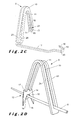
- Figure 1 shows the prefabricated concrete element, part of the prefabricated concrete element being removed to be able to see the embedded lifting tool according to the present invention.
- Figure 2a, 2b , 2c and 2d show four preferred embodiments of the lifting tool according to the present invention.
- the preferred embodiment of the prefabricated concrete floor element 1 of the present invention shown in figure 1 is a beam shaped element comprising opposite upright longitudinal sides 2, 3 and opposite upright transversal sides 4, 5.
- the floor element 1 is made of concrete and comprises at least a first 6 and a second 7 lower reinforcing wire which extend in longitudinal direction of the floor element 1, which are spaced apart from each other and are provided in a lower part of the floor element 1. Usually, the floor element will contain further spaced apart lower reinforcing wires.
- the prefabricated floor element 1 comprises a lifting tool 9.
- the lifting tool 9 is at least partly embedded in the concrete and is accessible from outside to permit cooperation with a lifting device.
- the lifting tool 9 comprises an upright section 10 which extends in height and longitudinal direction of the prefabricated floor element 1 and at least one cross member 16 which extends in transverse direction of the prefabricated floor element 1.
- any means considered suitable by the person skilled in the art may be provided to provide access from outside to the lifting tool 9.
- Access to the lifting tool 9 from outside may for instance be provided by means of a hole in the prefabricated floor element 1 as is shown on figure 1 at the position of the upright section 10 and the application point 11.
- the holes may be provided in the upright longitudinal sides 2, 3, or in the top face or in both the upright longitudinal sides 2, 3 and the top face of the floor element 1.
- the holes will usually be provided by removing part of the concrete during or after production of the floor element.
- the lifting tool will preferably be positioned substantially central of the top face of the prefabricated floor element and the hole to access the lifting tool is positioned accordingly in the top face of the prefabricated floor element.
- the lifting tools are preferably provided in the vicinity of the longitudinal 2, 3 or transversal 4, 5 upright sides of the floor element. Access to the lifting tool 9 may also be provided by having the lifting tool 9 protruding from the top face and/or upright sides 2, 3, 4, 5 of the prefabricated floor element 1.
- the upright section 10 of the lifting tool 9 may have any form considered suitable by the person skilled in the art, as long as it extends in height direction of the prefabricated floor element 1, comprises at least one application point 11 for cooperation with the lifting device to permit lifting of the prefabricated floor element 1 and comprises first receiving means 12 for receiving a first lower reinforcing wire 6.
- the upright section also extends in longitudinal direction. With extending in height direction is understood that the upright section may run parallel to the upright sides of the floor elements or extend under an angle with respect thereto. With extending in longitudinal direction of the floor element is understood that the upright section of the lifting tool may run parallel with one or more of the reinforcing wire, the upright longitudinal sides, or extend under an angle with respect thereto.
- the application point 11 is accessible from outside the prefabricated floor element 1, for instance through an opening in the upright section 10 of the lifting tool 9, or by having part of the lifting tool 9 protruding from the top face, bottom face or side face of the floor element, but any other suitable way may be chosen as well.
- the upright section 10 takes the form of a plate which extends in longitudinal and height direction of the floor element 1, which has a limited thickness in transverse direction of the prefabricated floor element, as is shown in figure 2B .
- the plate may have any form considered suitable by the person skilled in the art, and may for instance be rectangular, square or round or any other suitable shape.
- the upright section 10 has the shape of an inverted U as is shown in figure 2A , 2C and 2D .
- the inverted U may be made in one piece as is shown in figure 2A or may comprise a first 23 and a second 24 upright part which are spaced from each other in transverse direction of the prefabricated floor element 1 and which are connected to each other in a lower part of the prefabricated floor element 1 as is shown in figure 2C and 2D.
- Figure 2C and 2D further show that the first lower reinforcing wire may be received between the first 23 and the second 24 upright part of the upright section 10.
- the upright section 10 comprises first receiving means 12 with a lower space 13 in a lower part of the upright section for receiving the first lower reinforcing wire 6.
- the lower space 13 is delimited by at least an upper 14 and lower 15 member which limit upward and downward movement of the lifting tool 9 and by at least a first upright member 16 which limits movement of the lifting tool 9 in a first transverse direction of the prefabricated floor element 1.
- the upper member 14 of the lower space 13 may be provided by a part of the upright section 10 or may form part of the upright section 10 as is shown on figures 2A and 2B , or it may be provided by an additional member 21 which is moveable in height direction of the upright section 10 as is shown in figure 2C , or by a cross member 17 as is shown in figure 2D .
- the lower space 13 is formed by at least one recess in the upright section 10, as is shown in figure 2A .
- the at least one recess is delimited by an upper 14 and lower 15 member, which may for example take the shape of an upper and lower wall, and by at least a first upright member 16 which limits movement of the lifting tool 9 in a first transverse direction of the prefabricated floor element 1.
- the at least one recess may extend along part of the upright section 10 taken in longitudinal direction of the prefabricated floor element 1, but it may also extend along the whole length of the upright section 10 in longitudinal direction of the prefabricated floor element 1.
- the recess may take the form of two or more recesses ( fig.
- the recesses are preferably provided on opposite sides of the upright section 10 taken in longitudinal direction of the floor element, whereby both recesses are provided for receiving the first lower reinforcing wire 6 and whereby both recesses are delimited by an upper 14, lower 15 and first upright member 16 which limits movement of the lifting tool 9 in a first transversal direction of the prefabricated floor element 1.
- the recess will usually be provided in a lower region of the upright section, but this may vary with the dimensions of the lifting tool.
- the lower space 13 is formed by bending a lower part of the upright section 10 in a way an upper 14, lower 15 and first upright wall 16 is formed, as is shown on figure 2B .
- the lower part of the upright section 10 may be bent along part of its length, but preferably extends along its whole length in longitudinal direction of the prefabricated floor element 1.
- the lower space 13 may for example have a circular cross section.
- part of the lower space 13 is provided by an additional lower member 21, which is moveable in height direction of the upright section, as is shown in figure 2C .
- the additional lower member may comprise an upper and lower member, which are moveable independently from each other.
- the moveability of the additional lower member 21 has the advantage that lower reinforcing wires with varying diameters may be received within the lower space.
- the additional lower member 21 may for example take the shape of a ring which receives in it the first 23 and second 24 upright part of the upright section 10, whereby the first 23 upright part forms the first upright member 16 of the lower space 13.
- the lower member 15 of the lower space 13 may be formed by the lower member of the additional member 21 or by the lower part of the upright section 10, connecting the first 23 and second 24 upright part.
- the upper member 14 is formed by an upper wall of the additional lower member.
- the upper member 14 of the lower space 13 is provided by a cross member, as is shown in figure 2D .
- the first lower reinforcing wire is received between the first 23 and second 24 upright part of the upright section 10, whereby the first 23 or the second 24 upright part forms the first upright member 16 of the lower space 13.
- the second upright member 19 is formed by one of the two teeth of the cross member.
- the lower member 15 of the lower space 13 is formed by the lower part of the upright section 10, connecting the first 23 and second 24 upright part.
- transverse direction is understood to include transverse direction of the floor element or the lifting tool or a direction which extends under an angle with respect to the transverse direction of the floor element or the lifting tool.
- the cross member may be provided to fix the position of the first lower reinforcing wire, as is shown in figure 2D , and/or the second lower reinforcing wire, as is shown in figures 2A-2C .
- the cross member 17 comprises a connecting member 18 for connection to the second lower reinforcing wire 7.
- the connecting member 18 comprises a second upright member 19, which limits movement of the lifting tool 9 in a second transversal direction opposite to the first transversal direction.
- the cross member 17 may have any form considered suitable by the person skilled in the art, as long as it extends in transverse direction of the floor element and comprises a second upright member, which limits movement of the lifting tool in a second transverse direction of the prefabricated floor element opposite to the first transverse direction.
- the cross member may be provided to receive the first lower reinforcing wire, as is shown in figure 2D , or the second lower reinforcing wire, as is shown in figures 2A-2C .
- the cross member as shown in figure 2D extends in height and transverse direction of the prefabricated floor element, whereby the transverse direction may run parallel to the upright transversal sides of the prefabricated floor element or may extend under an angle with respect to the upright transversal sides of the floor element.
- the cross member as is shown in figure 2D comprises two teeth, with an opening in between.
- the first lower reinforcing wire is received within the opening.
- An upper edge of the opening functions as an upper member 14 of the lower space 13, hereby limiting movement of the lifting tool in upward direction.
- Preferably the upper edge of the opening is just above the first lower reinforcing wire, resulting in an optimum reduction of risk to movement of the lifting tool in downward direction.
- the two teeth extend on opposite sides of the first lower reinforcing wire and provide a stable lifting tool.
- One of the two teeth functions as the second upright member, which limits movement of the first reinforcing wire in a second transversal direction of the prefabricated floor element.
- the two teeth preferably comprise plastic caps (not shown) at the bottom.
- the caps are preferably adjustable in height. This has the advantage that the cross member can be adjusted in such a way that the upper edge of the opening is just above the first lower reinforcing wire, providing in an optimal reduction of the movement of the lifting tool in downward direction.
- the cross member as shown in figures 2A-2C extends in a horizontal plane, substantially parallel to the bottom of the prefabricated floor element.
- the cross member may extend along part of the length of the upright section 10 in longitudinal direction of the prefabricated floor element 1 as is shown in figure 2A , but it may also extend along the whole length of the upright section 10 in longitudinal direction of the prefabricated floor element 1 as is shown in figure 2B .
- the lifting tool 9 preferably comprises two or more cross members 17.
- a lifting tool with a cross member 17 which extends along the whole length of the upright section 10 or a lifting tool which comprises two or more cross members 17 are preferred because they provide a more stable lifting tool 9 and enlarge the contact surface between the lifting tool 9 and the concrete and thus the transfer of forces within a larger part of the prefabricated floor element 1.
- the cross member 17 may be made in one piece with the upright section 10 as is shown in figures 2B and 2C .
- the cross member 17 and the upright section 10 may also be made in two separate pieces which may be connected to each other with any suitable connection means known to the person skilled in the art, for instance by means of a screw or by means of cooperating positioning means, for instance a cooperating tongue and groove.
- the connecting member 18 is formed by bending an end part of the cross member 17 in a way a gap 20 is formed for receiving the second lower reinforcing wire 7.
- the gap 20 is at least delimited by a second upright member 19, as is shown in figures 2A, 2B and 2C .
- the end part of the cross member 17 may be bent upwards or downwards.
- the end part 18, 19 is preferably provided to exert a clamping action to the reinforcing wire received within the gap 20.
- the first receiving means 12 and/or the connecting member 18 are arranged in a way to exert a clamping action on respectively the first lower reinforcing wire 6, and/or the second reinforcing wire 7.
- the lifting tool is connected to a first and a second lower reinforcing wire
- both the first receiving means 12 and the connecting member 18 are arranged to exert a clamping action on respectively the first lower reinforcing wire 6 and the second reinforcing wire 7.
- the space 13 between the upper 14 and lower 15 member of the first receiving means 12 is equal to or somewhat smaller than the thickness of the first reinforcing wire 6.
- the space 13 may be formed by at least one recess in the upright section 10, by bending a lower part of the upright section 10, by providing the upright section 10 with an additional member 21, or by a cross member which is connected to the upright section, or by any other means ought suitable by the person skilled in the art.
- an additional member 21 is used to form the lower space 13
- the upper 14 and lower 15 wall of the additional member 21 are preferably moveable with respect to each other so that they can clamp the first lower reinforcing wire 6 between them.
- the height of the recess is preferably equal to or somewhat smaller than the thickness of the first lower reinforcing wire 6.
- Another possibility is to provide the upright section 10 of the lifting tool 9 with a first and a second recess on opposite longitudinal sides of the upright section 10, each of the recesses being delimited by at least an upper 14 and lower 15 wall defining a lower space 13 for receiving the first reinforcing wire 6.
- the upper 14 and lower 15 wall may extend parallel to the lower surface of the prefabricated floor element 1, whereby the lower space 13 formed between the upper 14 and lower 15 wall is preferably equal to or somewhat smaller than the thickness of the first lower reinforcing wire 6.
- the upper 14 and lower 15 walls make an angle with respect to the lower surface of the prefabricated floor element 1, whereby the lower and upper wall on one side of the upright section are bent towards respectively the lower and upper wall on the opposite side of the upright section, whereby the height of the lower space, formed by the lowest points of the upper walls and the highest points of the lower walls, is equal to or somewhat smaller than the thickness of the first lower reinforcing wire 6.
- a cross member which extends in a plane substantially parallel to the transverse side of the prefabricated floor element and is connected to the upright section of the lifting tool, provides the upper member of the lower space of the first receiving means.
- the first lower reinforcing wire may be clamped between the lower part of the upright section connecting the first 23 and second 24 upright part of the upright section 10, forming the lower member of the lower space, and the upper member 14 of the cross member 17.
- the connecting member 18 is arranged in a way the connecting member 18 may clamp the second lower reinforcing wire 7. This may for instance be done by bending an end part of the cross member 17 in a way a gap 20 is formed for receiving the second lower reinforcing wire 7, the size of the gap 20 being equal to or somewhat smaller than the size of the second reinforcing wire 7.
- any other means considered suitable by the person skilled in the art may be used.
- the first upright member 16 and the second upright member 19 of the lower space 13 act in opposite transverse directions and thus limit movement of the lifting tool 9 either in the same direction or in opposite directions in transverse direction of the prefabricated floor element 1.
- the opening of the lower space 13 defined by the recess in the upright section and the opening of the gap 20 defined by the connecting member 18 point towards each other, but they may equally point away from each other.
- Mounting of the lifting tool 9 to the first lower reinforcing wire 6 limits movement of the lifting tool 9 in longitudinal direction of the prefabricated floor element 1, because of friction between the first receiving means 12 of the upright section 10 and the first lower reinforcing wire 6.
- the lifting tool 9 is connected to a first and a second lower reinforcing wire, movement of the lifting tool 9 in longitudinal direction of the prefabricated floor element 1 is even more limited, because the cross member 17 is connected to the upright section 10 and the connecting member 18 of the cross member 17 is connected to the second lower reinforcing wire 7.
- Movement of the connecting member 18 in longitudinal direction is limited because of the occurrence of friction between the connecting member 18 and the second lower reinforcing wire 7 on the one hand and, because of friction between the first receiving means 12 of the upright section 10 and the first lower reinforcing wire 6 on the other hand.
- mounting the lifting tool 9 to the first lower reinforcing wire 6, limits movement of the lifting tool 9 in height, transverse and longitudinal direction of the prefabricated floor element 1 and limits torsion of the lifting tool 9. Therefore, after mounting the lifting tool 9 to the first lower reinforcing wire 6, the concrete may be immediately poured and cast. There is no need to establish an additional manual connection or apply additional acts during the further production of the prefabricated floor element in order to avoid movement of the lifting tool. In this way the production process of the prefabricated floor element 1 with embedded lifting tool 9 according to this invention may be done faster, compared to the ones used in the prior art. Furthermore, because the additional manual connection or acts may cause damage of the reinforcing wire, lifting of the prefabricated floor element 1 with an embedded lifting tool 9 according to this invention may be done in a more reliable way than compared to the prior art.
- the prefabricated floor element 1 preferably also comprises an upper reinforcing wire 8 extending in longitudinal direction of the prefabricated floor element 1 and provided in an upper part of the prefabricated floor element 1.
- the upright section 10 of the lifting tool 9 may be supported by the upper reinforcing wire 8.
- This further improves the stability of the lifting tool 9 allowing the lifting tool to stand on his own without the need for any external means.
- any forces or strains occurring within the lifting means during lifting may also be transferred to the upper reinforcing wire 8 and thus absorbed within a larger part of the prefabricated floor element 1.
- the upright section 10 may comprise in an upper part, second receiving means for receiving the upper reinforcing wire 8 and improve positioning.
- the second receiving means may be formed by a recess in the upper part of the upright section 10, by bending an upper part of the upright section 10 or by providing the upper part of the upright section 10 with an additional member or any other means considered suitable by the person skilled in the art.
- the second receiving means are formed by a first 23 and a second 24 upright member of the upright section 10 which are spaced from each other in transverse direction of the prefabricated floor element 1, in a way they may receive the upper reinforcing wire 8 between them.
- the second receiving means are delimited by a lower member and the upper reinforcing wire is provided on top of the lower member, because this provides for additional security during lifting of the prefabricated floor element 1. In this way, when the lower reinforcing wires 6, 7 would break during lifting of the prefabricated floor element 1, the lifting tool 9 is still connected to the upper reinforcing wire 8.
- the lifting tool may be mounted to the first and second lower reinforcing wire in the following way.
- the mounting is done by first sliding the first lower reinforcing wire into the lower space of the first receiving means provided in the upright section of the lifting tool and then connecting the connecting member of the cross member to the second lower reinforcing wire.
- mounting may be done in an easier way compared to the prior art, as the lifting tool may immediately be positioned in its final position and no rotation of the lifting tool about a vertical axis needs to be carried out.
Abstract
Description
- The present invention relates to a prefabricated concrete element comprising a first and a second upright longitudinal side, a first and a second upright transversal side, at least a first lower reinforcing wire which extends in longitudinal direction of the prefabricated floor element and is provided in a lower part of the prefabricated floor element, and a lifting tool to permit lifting the prefabricated floor element, the lifting tool being at least partly embedded in the concrete and being accessible from outside to permit cooperation with a lifting device, the lifting tool comprising an upright section which extends in height and longitudinal direction of the prefabricated floor element, wherein the upright section of the lifting tool comprises at least one application point for cooperation with the lifting device, according to the preamble of the first claim.
- Prefabricated concrete elements are frequently used in self supporting floor and ceiling construction. The floor or ceiling is built by placing a number of prefabricated concrete elements with their upright longitudinal sides against each other and with their mounting edges on supporting construction parts, such as walls and beams. In a next step the grooves between the elements are filled with concrete to provide a continuous layer. As a final step, if desired, a covering or finishing layer may be put on top of and/or against the lower face of the prefabricated concrete elements. The easy placement and immediate capability of carrying loads of the elements make it possible to build up floors quickly.
- However, the floor elements are usually not produced in situ at the construction site where they are needed, but are rather prefabricated by a supplier in large amounts. From there the floor elements are transported to the different construction sites for further use. On the construction site itself, the concrete elements also have to be lifted in order to permit positioning where required. The concrete elements thus have to be lifted a number of times. Because of the high weight of the prefabricated concrete elements and from an economical point of view, it is important that the lifting may be carried out using an appropriate lifting device. Thereby it is essential that the lifting is carried out safely and that risks at falling of an element during lifting are minimized.
- From the prior art a number of different solutions for lifting prefabricated floor elements are known.
-
EP-A-1344877 describes a method for fitting a hoisting hook in a prefabricated concrete element by using filling concrete, the prefabricated concrete element comprising one or more channels. To this end a passage is made in the still fresh concrete to one or more of the channels in the concrete element, shortly after the forming of the prefabricated concrete element. Next, a concrete-like material ('filling concrete') is poured or pressed, via the passage, in the part of the channel located adjacent the passage. The hoisting hook is placed in this uncured filling concrete and is fixed in the concrete element when the filing concrete hardens. However, the safety of the lifting of the prefabricated floor element is strongly dependent on the quality of the filling concrete. Moreover, when the filling concrete breaks, the hoisting hook is turned out the concrete element and the concrete element falls down. -
BE-A-1016424 -
EP-A-1555100 discloses a lifting loop comprising a central part in the shape of an inverted U which defines a lifting ring which protrudes from the top surface of a concrete floor element and which extends in longitudinal direction of the floor element. At the end parts of the legs of the inverted U, U-shaped fixing brackets are provided, which extend in opposite directions from the central part and in cross direction of the floor element. The lifting loop is mounted to a reinforcement cable of the concrete floor element in such a way the fixing brackets are positioned beneath the reinforcement cable and between the opposite lower ends of the central part, so that the lifting ring and the reinforcement cable extend in the same plane. This mounting may only be done by rotating the lifting loop about a vertical axis, after the reinforcing cable has been received in the U-shaped space of the central part. Upward movement and movement in transverse direction of the concrete element is limited. However, mounting of the lifting loop to the reinforcement cable does not limit movement of the lifting loop in longitudinal direction of the concrete element, nor does it limit torsion. In order to further limit movement of the lifting loop during casting of the concrete, it is necessary to apply additional means or acts to block or fix the lifting loop. This is done by exercising a pressure on the reinforcement cable on which the lifting loops are mounted. - It is an object of the present invention to provide a reinforced prefabricated floor element with an embedded lifting tool, which does not need additional fixation in order to minimize unwanted movement of the lifting tool during production of the prefabricated floor element after the lifting tool has been positioned to the reinforcing wire of the prefabricated floor element.
- This is achieved according to the present invention with a prefabricated concrete floor element showing the technical features of the characterizing part of the first claim.
- Thereto, the prefabricated concrete element according to this invention is characterized in that the upright section of the lifting tool comprises first receiving means comprising a lower space for receiving the first lower reinforcing wire, in that the lower space is delimited by at least an upper and a lower member and a first upright member which first upright member is provided to limit movement of the lifting tool in a first transverse direction of the prefabricated floor element, and in that the lifting tool further comprises a cross member which is connected to the upright section and which comprises a second upright member which is provided to limit movement of the lifting tool in a second transverse direction of the prefabricated floor element opposite to the first transverse direction. The lifting tool of the present invention mainly takes the form of a lifting hook.
- Because the lifting tool of the present invention contains parts which extend in height, longitudinal and transversal direction of the prefabricated floor element, the lifting tool can stand on its own. After mounting of the lifting tool to the first lower reinforcing wire, it is thus not necessary to hold or fix the lifting tool to the reinforcing wires in order to maintain it in the position in which it is to be incorporated in the prefabricated floor element.
- After mounting of the lifting tool to the first lower reinforcing wire, the concrete may immediately be poured and cast. It is hereby not necessary to apply additional fastening to fix the lifting tool in its position. Movement of the lifting tool is sufficiently limited by the mounting itself. This results in a prefabricated floor element with improved strength and load bearing capacity, because the risk to damaging the first lower reinforcing wire is minimized.
- Because the first lower reinforcing wire is received within the lower space of the lifting tool, whereby the lower space is delimited by at least an upper and lower member, upward and downward movement of the lifting tool is limited. Furthermore, the lower space of the first receiving means is delimited by a first upright member, which limits movement of the lifting tool in a first transverse direction of the prefabricated floor element. The cross member comprises a second upright member which limits movement of the lifting tool in a second transverse direction of the prefabricated floor element opposite the first transverse direction. Because the second upright member of the cross member and the first upright member of the upright section are adapted to act in opposite directions, the risk to movement of the lifting tool in transverse direction of the prefabricated floor element is limited. Limitation of movement may for example be achieved on the one hand by the presence of a recess in the upright section of the lifting tool which faces the cross member, and on the other hand by bending an end part of the cross member in order to define a gap, the opening of which faces the upright section.
- Mounting of the lifting tool to the first lower reinforcing wire further limits movement of the lifting tool in longitudinal direction of the prefabricated floor element and limits the risk to torsion of the lifting tool, i.e. rotation in a plane perpendicular to the plane defined by the upright section of the lifting tool. Movement of the lifting tool in longitudinal direction of the prefabricated floor element is counteracted because of the occurrence of friction between the first lower reinforcing wire and the first receiving means.
- The prefabricated floor element is lifted with a lifting device which is provided to cooperate with an application point provided in the upright section. Preferably the lifting tool is mounted to a first and a second lower reinforcing wire, with the purpose of obtaining an optimum reduction of the risk to torsion and movement of the lifting tool in transverse, height and longitudinal direction of the prefabricated floor element. In case the lifting tool is mounted on a first and a second lower reinforcing wire, any forces or strains occurring within the lifting means during lifting may be transferred to the first and second reinforcing wire and to the cross member and may be thus absorbed within a larger part of the prefabricated floor element. As a result, the risk to wearing or breaking of the reinforcing wire following lifting is reduced. Moreover, the mounting to a first and a second lower reinforcing wire provides for additional security during lifting. In case one reinforcing wire would break, the lifting tool is still connected to the other reinforcing wire. Moreover, because the lifting tool extends in longitudinal, height and transverse direction of the prefabricated floor element, the contact surface between the lifting tool and the concrete is increased, as a result of which any forces exerted to the lifting tool may be transferred to a large part of the prefabricated floor element.
- Optimum fixation of the positioning of the lifting tool in transverse, height and longitudinal direction of the prefabricated floor element and minimum risk to the occurrence of torsion is achieved in case the first receiving means are designed in a way they exert a clamping action on the first reinforcing wire. In case the lifting tool is also mounted to a second lower reinforcing wire, the connecting member of the cross member is preferably designed to exert a clamping action on the second reinforcing wire as well. Preferably, the first receiving means and the connecting member are designed in a way they exert a clamping action on the first, respectively the second reinforcing wire. More preferably the fixation forces exerted by the first receiving means and the connecting member on respectively the first and the second lower reinforcing wire point towards each other.
- The invention is further elucidated in the appending figures and description of the figures.
-
Figure 1 shows the prefabricated concrete element, part of the prefabricated concrete element being removed to be able to see the embedded lifting tool according to the present invention. -
Figure 2a, 2b ,2c and 2d show four preferred embodiments of the lifting tool according to the present invention. - The preferred embodiment of the prefabricated concrete floor element 1 of the present invention shown in
figure 1 is a beam shaped element comprising opposite uprightlongitudinal sides transversal sides 4, 5. The floor element 1 is made of concrete and comprises at least a first 6 and a second 7 lower reinforcing wire which extend in longitudinal direction of the floor element 1, which are spaced apart from each other and are provided in a lower part of the floor element 1. Usually, the floor element will contain further spaced apart lower reinforcing wires. To permit lifting of the prefabricated floor element 1, the prefabricated floor element 1 comprises alifting tool 9. Thelifting tool 9 is at least partly embedded in the concrete and is accessible from outside to permit cooperation with a lifting device. Thelifting tool 9 comprises anupright section 10 which extends in height and longitudinal direction of the prefabricated floor element 1 and at least onecross member 16 which extends in transverse direction of the prefabricated floor element 1. - Any means considered suitable by the person skilled in the art may be provided to provide access from outside to the
lifting tool 9. Access to thelifting tool 9 from outside may for instance be provided by means of a hole in the prefabricated floor element 1 as is shown onfigure 1 at the position of theupright section 10 and theapplication point 11. The holes may be provided in the uprightlongitudinal sides longitudinal sides transversal 4, 5 upright sides of the floor element. Access to thelifting tool 9 may also be provided by having thelifting tool 9 protruding from the top face and/orupright sides - The
upright section 10 of thelifting tool 9 may have any form considered suitable by the person skilled in the art, as long as it extends in height direction of the prefabricated floor element 1, comprises at least oneapplication point 11 for cooperation with the lifting device to permit lifting of the prefabricated floor element 1 and comprises first receiving means 12 for receiving a first lower reinforcingwire 6. Preferably, the upright section also extends in longitudinal direction. With extending in height direction is understood that the upright section may run parallel to the upright sides of the floor elements or extend under an angle with respect thereto. With extending in longitudinal direction of the floor element is understood that the upright section of the lifting tool may run parallel with one or more of the reinforcing wire, the upright longitudinal sides, or extend under an angle with respect thereto. - The
application point 11 is accessible from outside the prefabricated floor element 1, for instance through an opening in theupright section 10 of thelifting tool 9, or by having part of thelifting tool 9 protruding from the top face, bottom face or side face of the floor element, but any other suitable way may be chosen as well. - According to a first preferred embodiment of the
upright section 10, theupright section 10 takes the form of a plate which extends in longitudinal and height direction of the floor element 1, which has a limited thickness in transverse direction of the prefabricated floor element, as is shown infigure 2B . The plate may have any form considered suitable by the person skilled in the art, and may for instance be rectangular, square or round or any other suitable shape. - According to a second preferred embodiment of the invention, the
upright section 10 has the shape of an inverted U as is shown infigure 2A ,2C and 2D . The inverted U may be made in one piece as is shown infigure 2A or may comprise a first 23 and a second 24 upright part which are spaced from each other in transverse direction of the prefabricated floor element 1 and which are connected to each other in a lower part of the prefabricated floor element 1 as is shown infigure 2C and 2D. Figure 2C and 2D further show that the first lower reinforcing wire may be received between the first 23 and the second 24 upright part of theupright section 10. - The
upright section 10 comprises first receiving means 12 with alower space 13 in a lower part of the upright section for receiving the first lower reinforcingwire 6. Thelower space 13 is delimited by at least an upper 14 and lower 15 member which limit upward and downward movement of thelifting tool 9 and by at least afirst upright member 16 which limits movement of thelifting tool 9 in a first transverse direction of the prefabricated floor element 1. Theupper member 14 of thelower space 13 may be provided by a part of theupright section 10 or may form part of theupright section 10 as is shown onfigures 2A and 2B , or it may be provided by anadditional member 21 which is moveable in height direction of theupright section 10 as is shown infigure 2C , or by across member 17 as is shown infigure 2D . - According to a first preferred embodiment of the first receiving means 12, the
lower space 13 is formed by at least one recess in theupright section 10, as is shown infigure 2A . The at least one recess is delimited by an upper 14 and lower 15 member, which may for example take the shape of an upper and lower wall, and by at least afirst upright member 16 which limits movement of thelifting tool 9 in a first transverse direction of the prefabricated floor element 1. The at least one recess may extend along part of theupright section 10 taken in longitudinal direction of the prefabricated floor element 1, but it may also extend along the whole length of theupright section 10 in longitudinal direction of the prefabricated floor element 1. The recess may take the form of two or more recesses (fig. 2A ) or of one single recess for example provided in one leg of the inverted U. In case theupright section 10 comprises two recesses, the recesses are preferably provided on opposite sides of theupright section 10 taken in longitudinal direction of the floor element, whereby both recesses are provided for receiving the first lower reinforcingwire 6 and whereby both recesses are delimited by an upper 14, lower 15 andfirst upright member 16 which limits movement of thelifting tool 9 in a first transversal direction of the prefabricated floor element 1. The recess will usually be provided in a lower region of the upright section, but this may vary with the dimensions of the lifting tool. - According to a second preferred embodiment of the first receiving means 12, the
lower space 13 is formed by bending a lower part of theupright section 10 in a way an upper 14, lower 15 and firstupright wall 16 is formed, as is shown onfigure 2B . The lower part of theupright section 10 may be bent along part of its length, but preferably extends along its whole length in longitudinal direction of the prefabricated floor element 1. Thelower space 13 may for example have a circular cross section. - According to a third preferred embodiment of the first receiving means 12, part of the
lower space 13 is provided by an additionallower member 21, which is moveable in height direction of the upright section, as is shown infigure 2C . The additional lower member may comprise an upper and lower member, which are moveable independently from each other. The moveability of the additionallower member 21 has the advantage that lower reinforcing wires with varying diameters may be received within the lower space. The additionallower member 21 may for example take the shape of a ring which receives in it the first 23 and second 24 upright part of theupright section 10, whereby the first 23 upright part forms thefirst upright member 16 of thelower space 13. Thelower member 15 of thelower space 13 may be formed by the lower member of theadditional member 21 or by the lower part of theupright section 10, connecting the first 23 and second 24 upright part. Theupper member 14 is formed by an upper wall of the additional lower member. - According to a fourth preferred embodiment of the first receiving means, the
upper member 14 of thelower space 13 is provided by a cross member, as is shown infigure 2D . The first lower reinforcing wire is received between the first 23 and second 24 upright part of theupright section 10, whereby the first 23 or the second 24 upright part forms thefirst upright member 16 of thelower space 13. Thesecond upright member 19 is formed by one of the two teeth of the cross member. Thelower member 15 of thelower space 13 is formed by the lower part of theupright section 10, connecting the first 23 and second 24 upright part. Thecross member 17 is connected to theupright section 10, extends in transverse direction of the prefabricated floor element and of the lifting tool and comprises asecond upright member 19 for limiting movement of thelifting tool 9 in a second transverse direction opposite to the first transversal direction. Within the scope of this invention, transverse direction is understood to include transverse direction of the floor element or the lifting tool or a direction which extends under an angle with respect to the transverse direction of the floor element or the lifting tool. - The cross member may be provided to fix the position of the first lower reinforcing wire, as is shown in
figure 2D , and/or the second lower reinforcing wire, as is shown infigures 2A-2C . In the latter case thecross member 17 comprises a connectingmember 18 for connection to the second lower reinforcingwire 7. The connectingmember 18 comprises asecond upright member 19, which limits movement of thelifting tool 9 in a second transversal direction opposite to the first transversal direction. - The
cross member 17 may have any form considered suitable by the person skilled in the art, as long as it extends in transverse direction of the floor element and comprises a second upright member, which limits movement of the lifting tool in a second transverse direction of the prefabricated floor element opposite to the first transverse direction. The cross member may be provided to receive the first lower reinforcing wire, as is shown infigure 2D , or the second lower reinforcing wire, as is shown infigures 2A-2C . The cross member as shown infigure 2D extends in height and transverse direction of the prefabricated floor element, whereby the transverse direction may run parallel to the upright transversal sides of the prefabricated floor element or may extend under an angle with respect to the upright transversal sides of the floor element. The cross member as is shown infigure 2D comprises two teeth, with an opening in between. The first lower reinforcing wire is received within the opening. An upper edge of the opening functions as anupper member 14 of thelower space 13, hereby limiting movement of the lifting tool in upward direction. Preferably the upper edge of the opening is just above the first lower reinforcing wire, resulting in an optimum reduction of risk to movement of the lifting tool in downward direction. The two teeth extend on opposite sides of the first lower reinforcing wire and provide a stable lifting tool. One of the two teeth functions as the second upright member, which limits movement of the first reinforcing wire in a second transversal direction of the prefabricated floor element. The two teeth preferably comprise plastic caps (not shown) at the bottom. In this way the two teeth of the cross member cannot damage the material beneath. The caps are preferably adjustable in height. This has the advantage that the cross member can be adjusted in such a way that the upper edge of the opening is just above the first lower reinforcing wire, providing in an optimal reduction of the movement of the lifting tool in downward direction. - The cross member as shown in
figures 2A-2C extends in a horizontal plane, substantially parallel to the bottom of the prefabricated floor element. The cross member may extend along part of the length of theupright section 10 in longitudinal direction of the prefabricated floor element 1 as is shown infigure 2A , but it may also extend along the whole length of theupright section 10 in longitudinal direction of the prefabricated floor element 1 as is shown infigure 2B . In case thecross member 17 only extends along part of the length of theupright section 10 in longitudinal direction of the prefabricated floor element 1, thelifting tool 9 preferably comprises two ormore cross members 17. A lifting tool with across member 17 which extends along the whole length of theupright section 10 or a lifting tool which comprises two ormore cross members 17 are preferred because they provide a morestable lifting tool 9 and enlarge the contact surface between the liftingtool 9 and the concrete and thus the transfer of forces within a larger part of the prefabricated floor element 1. - The
cross member 17 may be made in one piece with theupright section 10 as is shown infigures 2B and2C . Thecross member 17 and theupright section 10 may also be made in two separate pieces which may be connected to each other with any suitable connection means known to the person skilled in the art, for instance by means of a screw or by means of cooperating positioning means, for instance a cooperating tongue and groove. - According to a first preferred embodiment of the connecting
member 18, the connectingmember 18 is formed by bending an end part of thecross member 17 in a way agap 20 is formed for receiving the second lower reinforcingwire 7. Thegap 20 is at least delimited by asecond upright member 19, as is shown infigures 2A, 2B and2C . The end part of thecross member 17 may be bent upwards or downwards. Theend part gap 20. - Preferably the first receiving means 12 and/or the connecting
member 18 are arranged in a way to exert a clamping action on respectively the first lower reinforcingwire 6, and/or the second reinforcingwire 7. In case the lifting tool is connected to a first and a second lower reinforcing wire, preferably both the first receiving means 12 and the connectingmember 18 are arranged to exert a clamping action on respectively the first lower reinforcingwire 6 and the second reinforcingwire 7. - In order to exert a clamping action on the first lower reinforcing
wire 6, thespace 13 between the upper 14 and lower 15 member of the first receiving means 12 is equal to or somewhat smaller than the thickness of the first reinforcingwire 6. Thespace 13 may be formed by at least one recess in theupright section 10, by bending a lower part of theupright section 10, by providing theupright section 10 with anadditional member 21, or by a cross member which is connected to the upright section, or by any other means ought suitable by the person skilled in the art. In the case anadditional member 21 is used to form thelower space 13, the upper 14 and lower 15 wall of theadditional member 21 are preferably moveable with respect to each other so that they can clamp the first lower reinforcingwire 6 between them. In the case a recess is used to form thelower space 13, the height of the recess is preferably equal to or somewhat smaller than the thickness of the first lower reinforcingwire 6. Another possibility is to provide theupright section 10 of thelifting tool 9 with a first and a second recess on opposite longitudinal sides of theupright section 10, each of the recesses being delimited by at least an upper 14 and lower 15 wall defining alower space 13 for receiving the first reinforcingwire 6. The upper 14 and lower 15 wall may extend parallel to the lower surface of the prefabricated floor element 1, whereby thelower space 13 formed between the upper 14 and lower 15 wall is preferably equal to or somewhat smaller than the thickness of the first lower reinforcingwire 6. Preferably the upper 14 and lower 15 walls make an angle with respect to the lower surface of the prefabricated floor element 1, whereby the lower and upper wall on one side of the upright section are bent towards respectively the lower and upper wall on the opposite side of the upright section, whereby the height of the lower space, formed by the lowest points of the upper walls and the highest points of the lower walls, is equal to or somewhat smaller than the thickness of the first lower reinforcingwire 6. Another possibility is that a cross member, which extends in a plane substantially parallel to the transverse side of the prefabricated floor element and is connected to the upright section of the lifting tool, provides the upper member of the lower space of the first receiving means. The first lower reinforcing wire may be clamped between the lower part of the upright section connecting the first 23 and second 24 upright part of theupright section 10, forming the lower member of the lower space, and theupper member 14 of thecross member 17. - In order to exert a clamping action on the second lower reinforcing
wire 7, the connectingmember 18 is arranged in a way the connectingmember 18 may clamp the second lower reinforcingwire 7. This may for instance be done by bending an end part of thecross member 17 in a way agap 20 is formed for receiving the second lower reinforcingwire 7, the size of thegap 20 being equal to or somewhat smaller than the size of the second reinforcingwire 7. However, any other means considered suitable by the person skilled in the art may be used. - The
first upright member 16 and thesecond upright member 19 of thelower space 13 act in opposite transverse directions and thus limit movement of thelifting tool 9 either in the same direction or in opposite directions in transverse direction of the prefabricated floor element 1. Infigure 2A for instance, the opening of thelower space 13 defined by the recess in the upright section and the opening of thegap 20 defined by the connectingmember 18 point towards each other, but they may equally point away from each other. - Mounting of the
lifting tool 9 to the first lower reinforcingwire 6 limits movement of thelifting tool 9 in longitudinal direction of the prefabricated floor element 1, because of friction between the first receiving means 12 of theupright section 10 and the first lower reinforcingwire 6. In case thelifting tool 9 is connected to a first and a second lower reinforcing wire, movement of thelifting tool 9 in longitudinal direction of the prefabricated floor element 1 is even more limited, because thecross member 17 is connected to theupright section 10 and the connectingmember 18 of thecross member 17 is connected to the second lower reinforcingwire 7. Movement of the connectingmember 18 in longitudinal direction is limited because of the occurrence of friction between the connectingmember 18 and the second lower reinforcingwire 7 on the one hand and, because of friction between the first receiving means 12 of theupright section 10 and the first lower reinforcingwire 6 on the other hand. - Mounting of the
lifting tool 9 to the first lower reinforcingwire 6 limits the risk to the occurrence of torsion, i.e. rotation in a plane perpendicular to the plane defined by the upright section of thelifting tool 9, or in other words rotation about the reinforcing wire. Infigure 2D for instance, where the lifting tool receives a first lower reinforcing wire, the risk to the occurrence of torsion is limited because the first lower receiving wire is received between the first 23 and the second 24 upright part of theupright section 10. In case thelifting tool 9 is connected to a first and a second lower reinforcing wire, as is the case infigures 2A-2C , the risk to the occurrence of torsion is limited because thecross member 17 is connected to theupright section 10, and the lifting tool is thus connected to a first and second reinforcing wire. Rotation of thecross member 17 would therefore cause rotation of theupright section 10, but this is limited because the first lower reinforcingwire 6 is received within the receiving means 12 of theupright section 10. - The larger the contact surface between the first receiving means 12 and the first lower reinforcing
wire 6 on the one hand and, in case the cross member is connected to a second lower reinforcing wire, between the connectingmember 18 of thecross member 17 and the second lower reinforcingwire 7 on the other hand, the larger the friction and the more the risk to movement of thelifting tool 9 in longitudinal direction of the prefabricated floor element 1 and torsion is reduced. - Summarizing, mounting the
lifting tool 9 to the first lower reinforcingwire 6, limits movement of thelifting tool 9 in height, transverse and longitudinal direction of the prefabricated floor element 1 and limits torsion of thelifting tool 9. Therefore, after mounting thelifting tool 9 to the first lower reinforcingwire 6, the concrete may be immediately poured and cast. There is no need to establish an additional manual connection or apply additional acts during the further production of the prefabricated floor element in order to avoid movement of the lifting tool. In this way the production process of the prefabricated floor element 1 with embeddedlifting tool 9 according to this invention may be done faster, compared to the ones used in the prior art. Furthermore, because the additional manual connection or acts may cause damage of the reinforcing wire, lifting of the prefabricated floor element 1 with an embeddedlifting tool 9 according to this invention may be done in a more reliable way than compared to the prior art. - Besides the first 6 and second 7 lower reinforcing wire, the prefabricated floor element 1 preferably also comprises an upper reinforcing
wire 8 extending in longitudinal direction of the prefabricated floor element 1 and provided in an upper part of the prefabricated floor element 1. In that way theupright section 10 of thelifting tool 9 may be supported by the upper reinforcingwire 8. This further improves the stability of thelifting tool 9 allowing the lifting tool to stand on his own without the need for any external means. In case thelifting tool 9 is supported by an upper reinforcingwire 8, any forces or strains occurring within the lifting means during lifting may also be transferred to the upper reinforcingwire 8 and thus absorbed within a larger part of the prefabricated floor element 1. Furthermore, in case thelifting tool 9 is supported by an upper reinforcingwire 8, movement of thelifting tool 9 after mounting of thelifting tool 9 to the first 6 and second 7 lower reinforcing wire is further limited. In fact, in case theupright section 10 is also supported by the upper reinforcingwire 8, friction between theupright section 10 and the upper reinforcing 8 further limits movement of thelifting tool 9. - Furthermore, the
upright section 10 may comprise in an upper part, second receiving means for receiving the upper reinforcingwire 8 and improve positioning. The second receiving means may be formed by a recess in the upper part of theupright section 10, by bending an upper part of theupright section 10 or by providing the upper part of theupright section 10 with an additional member or any other means considered suitable by the person skilled in the art. According to a preferred embodiment of the second receiving means, the second receiving means are formed by a first 23 and a second 24 upright member of theupright section 10 which are spaced from each other in transverse direction of the prefabricated floor element 1, in a way they may receive the upper reinforcingwire 8 between them. The larger the contact surface between the second receiving means and the upper reinforcingwire 8, the larger the friction is and the more movement of thelifting tool 9 of the prefabricated floor element 1 is avoided. Preferably the second receiving means are delimited by a lower member and the upper reinforcing wire is provided on top of the lower member, because this provides for additional security during lifting of the prefabricated floor element 1. In this way, when the lower reinforcingwires lifting tool 9 is still connected to the upper reinforcingwire 8. - In case the lifting tool is connected to a first and a second lower reinforcing wire, as is the case in
figures 2A-2C , the lifting tool may be mounted to the first and second lower reinforcing wire in the following way. The mounting is done by first sliding the first lower reinforcing wire into the lower space of the first receiving means provided in the upright section of the lifting tool and then connecting the connecting member of the cross member to the second lower reinforcing wire. Thus, mounting may be done in an easier way compared to the prior art, as the lifting tool may immediately be positioned in its final position and no rotation of the lifting tool about a vertical axis needs to be carried out.
Claims (14)
- A prefabricated concrete floor element (1) comprising a first (2) and a second (3) upright longitudinal side, a first (4) and a second (5) upright transversal side, at least a first (6) lower reinforcing wire which extends in longitudinal direction of the prefabricated floor element and is provided in a lower part of the prefabricated floor element, and a lifting tool (9) to permit lifting the prefabricated floor element, the lifting tool (9) being at least partly embedded in the concrete and being accessible from outside to permit cooperation with a lifting device, the lifting tool (9) comprising an upright section (10) which extends in height and longitudinal direction of the prefabricated floor element, wherein the upright section (10) of the lifting tool comprises at least one application point (11) for cooperation with the lifting device, characterized in that the upright section (10) of the lifting tool comprises first receiving means (12) comprising a lower space (13) for receiving the first lower reinforcing wire (6), in that the lower space (13) is delimited by at least an upper (14) and a lower (15) member and a first upright member (16) which first upright member is provided to limit movement of the lifting tool (9) in a first transverse direction of the prefabricated floor element, and in that the lifting tool (9) further comprises a cross member (17) which is connected to the upright section (10) and which comprises a second upright member which is provided to limit movement of the lifting tool (9) in a second transverse direction of the prefabricated floor element opposite to the first transverse direction.
- A prefabricated concrete element according to claim 1, characterized in that the the first receiving means (12) are arranged to exert a clamping action on the first lower reinforcing wire (6).
- A prefabricated concrete element according to anyone of claims 1-2, characterized in that the prefabricated floor element comprises an upper reinforcing wire (8) extending in longitudinal of the prefabricated floor element and provided in an upper part of the prefabricated floor element and in that the upright section (10) is supported by the upper reinforcing wire (8).
- A prefabricated concrete element according to anyone of claims 1-3, characterized in that the upright section (10) comprises a first (23) and a second (24) upright part which are spaced from each other in transverse direction of the prefabricated floor element for receiving the first lower wire (6) therebetween.
- A prefabricated concrete element according to claim 4, characterized in that the upper member (14) of the lower space (13) for receiving the first lower reinforcing wire, is provided by the cross member (17).
- A prefabricated concrete element according to anyone of claims 1-4, characterized in that cross member (17) comprises a connecting member (18) for connection to a second lower reinforcing wire (7).
- A prefabricated concrete element according to claim 6, characterized in that the connecting member (18) is arranged to exert a clamping action to the second lower reinforcing wire (7).
- A prefabricated concrete element according to anyone of claims 6-7, characterized in that the first receiving means (12) are formed by at least one lower recess in the upright section for providing the lower space (13) for receiving the first lower reinforcing wire (6).
- A prefabricated concrete element according to anyone of claims 6-7, characterized in that the first receiving means (12) are formed by bending a lower part of the upright section for providing the lower space (13) for receiving the first lower reinforcing wire (6).
- A prefabricated concrete element according to anyone of claims 6-7, characterized in that the upright section (10) comprises a first (23) and a second (24) upright part which are spaced from each other in transverse direction of the prefabricated floor element.
- A prefabricated concrete element according to claim 10, characterized in that the upright section (10) of the lifting tool (9) comprises an additional member (21) which is moveable in height direction of the upright section (10), for providing the upper member (14) of the lower space (13) for receiving the first lower reinforcing wire (6).
- A prefabricated concrete element according to anyone of claims 6-11, characterized in that an end part of the cross member (17) is bent to provide a gap (20) for receiving the second lower reinforcing wire (7).
- A prefabricated concrete element according to anyone of claims 3-12, characterized in that the upright section (10) comprises in an upper part second receiving means for receiving the upper reinforcing wire (8).
- A lifting tool (9) for lifting a prefabricated floor element (1), comprising an upright section (10) extending in height and longitudinal direction of the prefabricated floor element (1), the upright section (10) comprising at least one application point (11) for cooperation with a lifting device, characterized in that the upright section (10) further comprises first receiving means (12), in that the first receiving means (12) comprise a lower space (13) for receiving a first lower reinforcing wire (6) of the prefabricated floor element (1), in that the lower space (13) is delimited by at least an upper (14), lower (15) and first upright member (16), the first upright member (16) limiting movement of the lifting tool (9) in a first transverse direction of the prefabricated floor element (1), and in that the lifting tool (9) further comprises a cross member (17) which extends in transverse direction of the prefabricated floor element (1) and is connected to the upright section (10), the cross member (18) comprising a second upright member (19), the second upright member (19) limiting movement of the lifting tool (9) in a second transverse direction of the prefabricated floor element (1) opposite to the first transverse direction.
Priority Applications (1)
| Application Number | Priority Date | Filing Date | Title |
|---|---|---|---|
| EP20070124059 EP2075392B1 (en) | 2007-12-24 | 2007-12-24 | Prefabricated concrete element |
Applications Claiming Priority (1)
| Application Number | Priority Date | Filing Date | Title |
|---|---|---|---|
| EP20070124059 EP2075392B1 (en) | 2007-12-24 | 2007-12-24 | Prefabricated concrete element |
Publications (2)
| Publication Number | Publication Date |
|---|---|
| EP2075392A1 true EP2075392A1 (en) | 2009-07-01 |
| EP2075392B1 EP2075392B1 (en) | 2015-03-18 |
Family
ID=39364041
Family Applications (1)
| Application Number | Title | Priority Date | Filing Date |
|---|---|---|---|
| EP20070124059 Not-in-force EP2075392B1 (en) | 2007-12-24 | 2007-12-24 | Prefabricated concrete element |
Country Status (1)
| Country | Link |
|---|---|
| EP (1) | EP2075392B1 (en) |
Cited By (5)
| Publication number | Priority date | Publication date | Assignee | Title |
|---|---|---|---|---|
| GB2495902A (en) * | 2011-09-05 | 2013-05-01 | Hoesch Building Systems Ltd | Security panel for use in construction of secure structures within buildings |
| NO341267B1 (en) * | 2014-08-04 | 2017-10-02 | Svein Berg Holding As | Building element, building comprising one or more building elements and method for joining building elements and supporting elements |
| EP3428109A1 (en) * | 2017-07-13 | 2019-01-16 | Marcel Arteon | Dynamic and adaptive anchor for hoisting a construction element, especially thin elements, multi-configurations and multiple forces |
| CN111622408A (en) * | 2020-04-21 | 2020-09-04 | 上海二十冶建设有限公司 | Hollow floor system using cylindrical mold core and matched filling device |
| GB2600748A (en) * | 2020-11-09 | 2022-05-11 | Sapphire Balconies Ltd | Balcony developments |
Citations (7)
| Publication number | Priority date | Publication date | Assignee | Title |
|---|---|---|---|---|
| DE3904772C1 (en) * | 1989-02-17 | 1990-06-13 | Unistrut Europe Plc, Bedford, Gb | |
| US5242249A (en) * | 1991-08-12 | 1993-09-07 | Mmi Products | Pre-cast panel lifting insert |
| US6230447B1 (en) * | 2000-07-06 | 2001-05-15 | George E. Pribyl | Lifting anchor for prefabricated concrete panels |
| US20040010984A1 (en) * | 2002-07-12 | 2004-01-22 | Wright William James | Anchoring device |
| EP1555100A1 (en) | 2004-01-15 | 2005-07-20 | Soprel | Manufacturing method for prestressed concrete hollow slabs and slabs obtained by that method |
| BE1016424A6 (en) * | 2005-01-24 | 2006-10-03 | Echo | Lifting hook for prefabricated reinforced concrete slab, comprises U shaped loop section and cross direction part for positioning beneath slab reinforcing structure |
| FR2897627A1 (en) | 2006-02-21 | 2007-08-24 | Jacques Gauvrit | Load anchor for use in e.g. slab, has L shaped vertical branch for providing ring, and L shaped horizontal branch with hook and lug for locking horizontal branch with armature of armed concrete plate |
-
2007
- 2007-12-24 EP EP20070124059 patent/EP2075392B1/en not_active Not-in-force
Patent Citations (7)
| Publication number | Priority date | Publication date | Assignee | Title |
|---|---|---|---|---|
| DE3904772C1 (en) * | 1989-02-17 | 1990-06-13 | Unistrut Europe Plc, Bedford, Gb | |
| US5242249A (en) * | 1991-08-12 | 1993-09-07 | Mmi Products | Pre-cast panel lifting insert |
| US6230447B1 (en) * | 2000-07-06 | 2001-05-15 | George E. Pribyl | Lifting anchor for prefabricated concrete panels |
| US20040010984A1 (en) * | 2002-07-12 | 2004-01-22 | Wright William James | Anchoring device |
| EP1555100A1 (en) | 2004-01-15 | 2005-07-20 | Soprel | Manufacturing method for prestressed concrete hollow slabs and slabs obtained by that method |
| BE1016424A6 (en) * | 2005-01-24 | 2006-10-03 | Echo | Lifting hook for prefabricated reinforced concrete slab, comprises U shaped loop section and cross direction part for positioning beneath slab reinforcing structure |
| FR2897627A1 (en) | 2006-02-21 | 2007-08-24 | Jacques Gauvrit | Load anchor for use in e.g. slab, has L shaped vertical branch for providing ring, and L shaped horizontal branch with hook and lug for locking horizontal branch with armature of armed concrete plate |
Cited By (10)
| Publication number | Priority date | Publication date | Assignee | Title |
|---|---|---|---|---|
| GB2495902A (en) * | 2011-09-05 | 2013-05-01 | Hoesch Building Systems Ltd | Security panel for use in construction of secure structures within buildings |
| GB2495902B (en) * | 2011-09-05 | 2017-10-18 | Hoesch Building Systems Ltd | Security panel |
| NO341267B1 (en) * | 2014-08-04 | 2017-10-02 | Svein Berg Holding As | Building element, building comprising one or more building elements and method for joining building elements and supporting elements |
| US10081942B2 (en) | 2014-08-04 | 2018-09-25 | Svein Berg Holding As | Building element, a building comprising one or more such building elements and a method for joining such a building element and a support element |
| EP3428109A1 (en) * | 2017-07-13 | 2019-01-16 | Marcel Arteon | Dynamic and adaptive anchor for hoisting a construction element, especially thin elements, multi-configurations and multiple forces |
| FR3068962A1 (en) * | 2017-07-13 | 2019-01-18 | Marcel Arteon | DYNAMIC AND EVOLVING ANCHOR FOR LIFTING A BUILDING ELEMENT, IN PARTICULAR OF LOW THICKNESS, MULTICONFIGURATION AND MULTI-STRENGTH |
| CN111622408A (en) * | 2020-04-21 | 2020-09-04 | 上海二十冶建设有限公司 | Hollow floor system using cylindrical mold core and matched filling device |
| CN111622408B (en) * | 2020-04-21 | 2021-11-16 | 上海二十冶建设有限公司 | Hollow floor system using cylindrical mold core and matched filling device |
| GB2600748A (en) * | 2020-11-09 | 2022-05-11 | Sapphire Balconies Ltd | Balcony developments |
| GB2600748B (en) * | 2020-11-09 | 2023-03-08 | Sapphire Balconies Ltd | Balcony developments |
Also Published As
| Publication number | Publication date |
|---|---|
| EP2075392B1 (en) | 2015-03-18 |
Similar Documents
| Publication | Publication Date | Title |
|---|---|---|
| EP2075392B1 (en) | Prefabricated concrete element | |
| CA2740498A1 (en) | A lifting device and method for concrete elements | |
| WO2009010366A1 (en) | Improved girders for reinforcing concrete and method for connecting them to pillars in order to provide continuity from bay to bay | |
| RU2541000C2 (en) | Fixation method of lifting eye on concrete element obtained by method of casting into sliding form, and support for lifting eye | |
| KR101471393B1 (en) | Anchor socket structure for bridge support | |
| KR101119050B1 (en) | structure for filling-up a steel reinforced concrete on H shaped section steel in slab bridge | |
| KR101960241B1 (en) | Safety against overturning type multifunctional reinforcing bar supporter used in concrete slab processing | |
| KR101374701B1 (en) | Concrete beam construction method with anchorage apparatus for bi-pressing compression member | |
| RU2554364C2 (en) | Supporting device of anchor for concrete elements lifting | |
| KR20060037137A (en) | Space preservation device for construction support | |
| KR101171746B1 (en) | Method execution silo | |
| EP2037058B1 (en) | Floor element with lifting tools | |
| KR20110058051A (en) | A combined concrete leveling ruler and pouring stepping member | |
| CN212742218U (en) | Wet seam template reinforcing apparatus in construction is assembled to bridge segment | |
| KR100762404B1 (en) | Iron bar support | |
| KR100403989B1 (en) | Bridge slab construction method and precast concrete plate applied therein | |
| CN210315185U (en) | Box girder | |
| CN210562997U (en) | Prefabricated column assembly | |
| KR101298399B1 (en) | Support for a upper reinforcing bar of footings | |
| CN207878798U (en) | A kind of functional steel tendon protective layer control device | |
| KR101960035B1 (en) | Apparatus for adjusting height and method for replacing bridge bearing using the same | |
| US6180046B1 (en) | Method and apparatus for casting wire reinforced members utilizing members for positioning and supporting the wire reinforcements | |
| KR101705202B1 (en) | U-head jack assembly | |
| CN219864193U (en) | Prefabricated wall bottom limiting and supporting tool | |
| KR20010111157A (en) | Spring support for slab |
Legal Events
| Date | Code | Title | Description |
|---|---|---|---|
| PUAI | Public reference made under article 153(3) epc to a published international application that has entered the european phase |
Free format text: ORIGINAL CODE: 0009012 |
|
| AK | Designated contracting states |
Kind code of ref document: A1 Designated state(s): AT BE BG CH CY CZ DE DK EE ES FI FR GB GR HU IE IS IT LI LT LU LV MC MT NL PL PT RO SE SI SK TR |
|
| AX | Request for extension of the european patent |
Extension state: AL BA HR MK |
|
| AKX | Designation fees paid | ||
| REG | Reference to a national code |
Ref country code: DE Ref legal event code: 8566 |
|
| 17P | Request for examination filed |
Effective date: 20100317 |
|
| RBV | Designated contracting states (corrected) |
Designated state(s): AT BE BG CH CY CZ DE DK EE ES FI FR GB GR HU IE IS IT LI LT LU LV MC MT NL PL PT RO SE SI SK TR |
|
| 17Q | First examination report despatched |
Effective date: 20100412 |
|
| GRAP | Despatch of communication of intention to grant a patent |
Free format text: ORIGINAL CODE: EPIDOSNIGR1 |
|
| INTG | Intention to grant announced |
Effective date: 20140306 |
|
| GRAS | Grant fee paid |
Free format text: ORIGINAL CODE: EPIDOSNIGR3 |
|
| GRAP | Despatch of communication of intention to grant a patent |
Free format text: ORIGINAL CODE: EPIDOSNIGR1 |
|
| INTG | Intention to grant announced |
Effective date: 20141113 |
|
| GRAA | (expected) grant |
Free format text: ORIGINAL CODE: 0009210 |
|
| AK | Designated contracting states |
Kind code of ref document: B1 Designated state(s): AT BE BG CH CY CZ DE DK EE ES FI FR GB GR HU IE IS IT LI LT LU LV MC MT NL PL PT RO SE SI SK TR |
|
| REG | Reference to a national code |
Ref country code: GB Ref legal event code: FG4D |
|
| REG | Reference to a national code |
Ref country code: CH Ref legal event code: EP |
|
| REG | Reference to a national code |
Ref country code: IE Ref legal event code: FG4D |
|
| REG | Reference to a national code |
Ref country code: AT Ref legal event code: REF Ref document number: 716691 Country of ref document: AT Kind code of ref document: T Effective date: 20150415 |
|
| RAP2 | Party data changed (patent owner data changed or rights of a patent transferred) |
Owner name: PREFACO NV |
|
| REG | Reference to a national code |
Ref country code: DE Ref legal event code: R096 Ref document number: 602007040658 Country of ref document: DE Effective date: 20150430 |
|
| REG | Reference to a national code |
Ref country code: NL Ref legal event code: VDEP Effective date: 20150318 |
|
| REG | Reference to a national code |
Ref country code: NL Ref legal event code: VDEP Effective date: 20150318 |
|
| PG25 | Lapsed in a contracting state [announced via postgrant information from national office to epo] |
Ref country code: FI Free format text: LAPSE BECAUSE OF FAILURE TO SUBMIT A TRANSLATION OF THE DESCRIPTION OR TO PAY THE FEE WITHIN THE PRESCRIBED TIME-LIMIT Effective date: 20150318 Ref country code: SE Free format text: LAPSE BECAUSE OF FAILURE TO SUBMIT A TRANSLATION OF THE DESCRIPTION OR TO PAY THE FEE WITHIN THE PRESCRIBED TIME-LIMIT Effective date: 20150318 Ref country code: LT Free format text: LAPSE BECAUSE OF FAILURE TO SUBMIT A TRANSLATION OF THE DESCRIPTION OR TO PAY THE FEE WITHIN THE PRESCRIBED TIME-LIMIT Effective date: 20150318 |
|
| REG | Reference to a national code |
Ref country code: AT Ref legal event code: MK05 Ref document number: 716691 Country of ref document: AT Kind code of ref document: T Effective date: 20150318 |
|
| REG | Reference to a national code |
Ref country code: LT Ref legal event code: MG4D |
|
| PG25 | Lapsed in a contracting state [announced via postgrant information from national office to epo] |
Ref country code: LV Free format text: LAPSE BECAUSE OF FAILURE TO SUBMIT A TRANSLATION OF THE DESCRIPTION OR TO PAY THE FEE WITHIN THE PRESCRIBED TIME-LIMIT Effective date: 20150318 Ref country code: GR Free format text: LAPSE BECAUSE OF FAILURE TO SUBMIT A TRANSLATION OF THE DESCRIPTION OR TO PAY THE FEE WITHIN THE PRESCRIBED TIME-LIMIT Effective date: 20150619 |
|
| PG25 | Lapsed in a contracting state [announced via postgrant information from national office to epo] |
Ref country code: NL Free format text: LAPSE BECAUSE OF FAILURE TO SUBMIT A TRANSLATION OF THE DESCRIPTION OR TO PAY THE FEE WITHIN THE PRESCRIBED TIME-LIMIT Effective date: 20150318 |
|
| PG25 | Lapsed in a contracting state [announced via postgrant information from national office to epo] |
Ref country code: CZ Free format text: LAPSE BECAUSE OF FAILURE TO SUBMIT A TRANSLATION OF THE DESCRIPTION OR TO PAY THE FEE WITHIN THE PRESCRIBED TIME-LIMIT Effective date: 20150318 Ref country code: ES Free format text: LAPSE BECAUSE OF FAILURE TO SUBMIT A TRANSLATION OF THE DESCRIPTION OR TO PAY THE FEE WITHIN THE PRESCRIBED TIME-LIMIT Effective date: 20150318 Ref country code: EE Free format text: LAPSE BECAUSE OF FAILURE TO SUBMIT A TRANSLATION OF THE DESCRIPTION OR TO PAY THE FEE WITHIN THE PRESCRIBED TIME-LIMIT Effective date: 20150318 Ref country code: PT Free format text: LAPSE BECAUSE OF FAILURE TO SUBMIT A TRANSLATION OF THE DESCRIPTION OR TO PAY THE FEE WITHIN THE PRESCRIBED TIME-LIMIT Effective date: 20150720 Ref country code: SK Free format text: LAPSE BECAUSE OF FAILURE TO SUBMIT A TRANSLATION OF THE DESCRIPTION OR TO PAY THE FEE WITHIN THE PRESCRIBED TIME-LIMIT Effective date: 20150318 Ref country code: RO Free format text: LAPSE BECAUSE OF FAILURE TO SUBMIT A TRANSLATION OF THE DESCRIPTION OR TO PAY THE FEE WITHIN THE PRESCRIBED TIME-LIMIT Effective date: 20150318 |
|
| PG25 | Lapsed in a contracting state [announced via postgrant information from national office to epo] |
Ref country code: IS Free format text: LAPSE BECAUSE OF FAILURE TO SUBMIT A TRANSLATION OF THE DESCRIPTION OR TO PAY THE FEE WITHIN THE PRESCRIBED TIME-LIMIT Effective date: 20150718 Ref country code: PL Free format text: LAPSE BECAUSE OF FAILURE TO SUBMIT A TRANSLATION OF THE DESCRIPTION OR TO PAY THE FEE WITHIN THE PRESCRIBED TIME-LIMIT Effective date: 20150318 Ref country code: AT Free format text: LAPSE BECAUSE OF FAILURE TO SUBMIT A TRANSLATION OF THE DESCRIPTION OR TO PAY THE FEE WITHIN THE PRESCRIBED TIME-LIMIT Effective date: 20150318 |
|
| REG | Reference to a national code |
Ref country code: DE Ref legal event code: R097 Ref document number: 602007040658 Country of ref document: DE |
|
| PG25 | Lapsed in a contracting state [announced via postgrant information from national office to epo] |
Ref country code: IT Free format text: LAPSE BECAUSE OF FAILURE TO SUBMIT A TRANSLATION OF THE DESCRIPTION OR TO PAY THE FEE WITHIN THE PRESCRIBED TIME-LIMIT Effective date: 20150318 |
|
| PLBE | No opposition filed within time limit |
Free format text: ORIGINAL CODE: 0009261 |
|
| STAA | Information on the status of an ep patent application or granted ep patent |
Free format text: STATUS: NO OPPOSITION FILED WITHIN TIME LIMIT |
|
| PG25 | Lapsed in a contracting state [announced via postgrant information from national office to epo] |
Ref country code: DK Free format text: LAPSE BECAUSE OF FAILURE TO SUBMIT A TRANSLATION OF THE DESCRIPTION OR TO PAY THE FEE WITHIN THE PRESCRIBED TIME-LIMIT Effective date: 20150318 |
|
| 26N | No opposition filed |
Effective date: 20151221 |
|
| PG25 | Lapsed in a contracting state [announced via postgrant information from national office to epo] |
Ref country code: SI Free format text: LAPSE BECAUSE OF FAILURE TO SUBMIT A TRANSLATION OF THE DESCRIPTION OR TO PAY THE FEE WITHIN THE PRESCRIBED TIME-LIMIT Effective date: 20150318 |
|
| PG25 | Lapsed in a contracting state [announced via postgrant information from national office to epo] |
Ref country code: BE Free format text: LAPSE BECAUSE OF NON-PAYMENT OF DUE FEES Effective date: 20151231 |
|
| REG | Reference to a national code |
Ref country code: DE Ref legal event code: R119 Ref document number: 602007040658 Country of ref document: DE |
|
| PG25 | Lapsed in a contracting state [announced via postgrant information from national office to epo] |
Ref country code: LU Free format text: LAPSE BECAUSE OF FAILURE TO SUBMIT A TRANSLATION OF THE DESCRIPTION OR TO PAY THE FEE WITHIN THE PRESCRIBED TIME-LIMIT Effective date: 20151224 Ref country code: MC Free format text: LAPSE BECAUSE OF FAILURE TO SUBMIT A TRANSLATION OF THE DESCRIPTION OR TO PAY THE FEE WITHIN THE PRESCRIBED TIME-LIMIT Effective date: 20150318 |
|
| REG | Reference to a national code |
Ref country code: CH Ref legal event code: PL |
|
| GBPC | Gb: european patent ceased through non-payment of renewal fee |
Effective date: 20151224 |
|
| PG25 | Lapsed in a contracting state [announced via postgrant information from national office to epo] |
Ref country code: BE Free format text: LAPSE BECAUSE OF FAILURE TO SUBMIT A TRANSLATION OF THE DESCRIPTION OR TO PAY THE FEE WITHIN THE PRESCRIBED TIME-LIMIT Effective date: 20150318 |
|
| REG | Reference to a national code |
Ref country code: IE Ref legal event code: MM4A |
|
| REG | Reference to a national code |
Ref country code: FR Ref legal event code: ST Effective date: 20160831 |
|
| PG25 | Lapsed in a contracting state [announced via postgrant information from national office to epo] |
Ref country code: CH Free format text: LAPSE BECAUSE OF NON-PAYMENT OF DUE FEES Effective date: 20151231 Ref country code: LI Free format text: LAPSE BECAUSE OF NON-PAYMENT OF DUE FEES Effective date: 20151231 Ref country code: DE Free format text: LAPSE BECAUSE OF NON-PAYMENT OF DUE FEES Effective date: 20160701 Ref country code: IE Free format text: LAPSE BECAUSE OF NON-PAYMENT OF DUE FEES Effective date: 20151224 Ref country code: GB Free format text: LAPSE BECAUSE OF NON-PAYMENT OF DUE FEES Effective date: 20151224 |
|
| PG25 | Lapsed in a contracting state [announced via postgrant information from national office to epo] |
Ref country code: FR Free format text: LAPSE BECAUSE OF NON-PAYMENT OF DUE FEES Effective date: 20151231 |
|
| PG25 | Lapsed in a contracting state [announced via postgrant information from national office to epo] |
Ref country code: HU Free format text: LAPSE BECAUSE OF FAILURE TO SUBMIT A TRANSLATION OF THE DESCRIPTION OR TO PAY THE FEE WITHIN THE PRESCRIBED TIME-LIMIT; INVALID AB INITIO Effective date: 20071224 Ref country code: BG Free format text: LAPSE BECAUSE OF FAILURE TO SUBMIT A TRANSLATION OF THE DESCRIPTION OR TO PAY THE FEE WITHIN THE PRESCRIBED TIME-LIMIT Effective date: 20150318 |
|
| PG25 | Lapsed in a contracting state [announced via postgrant information from national office to epo] |
Ref country code: CY Free format text: LAPSE BECAUSE OF FAILURE TO SUBMIT A TRANSLATION OF THE DESCRIPTION OR TO PAY THE FEE WITHIN THE PRESCRIBED TIME-LIMIT Effective date: 20150318 |
|
| PG25 | Lapsed in a contracting state [announced via postgrant information from national office to epo] |
Ref country code: MT Free format text: LAPSE BECAUSE OF FAILURE TO SUBMIT A TRANSLATION OF THE DESCRIPTION OR TO PAY THE FEE WITHIN THE PRESCRIBED TIME-LIMIT Effective date: 20150318 Ref country code: TR Free format text: LAPSE BECAUSE OF FAILURE TO SUBMIT A TRANSLATION OF THE DESCRIPTION OR TO PAY THE FEE WITHIN THE PRESCRIBED TIME-LIMIT Effective date: 20150318 |