EP2075206A1 - Conveyor - Google Patents
Conveyor Download PDFInfo
- Publication number
- EP2075206A1 EP2075206A1 EP08020462A EP08020462A EP2075206A1 EP 2075206 A1 EP2075206 A1 EP 2075206A1 EP 08020462 A EP08020462 A EP 08020462A EP 08020462 A EP08020462 A EP 08020462A EP 2075206 A1 EP2075206 A1 EP 2075206A1
- Authority
- EP
- European Patent Office
- Prior art keywords
- belt
- pair
- meandering
- cams
- rollers
- Prior art date
- Legal status (The legal status is an assumption and is not a legal conclusion. Google has not performed a legal analysis and makes no representation as to the accuracy of the status listed.)
- Withdrawn
Links
- 238000001514 detection method Methods 0.000 claims abstract description 27
- 238000000034 method Methods 0.000 description 4
- 229910000831 Steel Inorganic materials 0.000 description 3
- 230000004048 modification Effects 0.000 description 3
- 238000012986 modification Methods 0.000 description 3
- 239000010959 steel Substances 0.000 description 3
- 230000001105 regulatory effect Effects 0.000 description 2
- 230000033001 locomotion Effects 0.000 description 1
- 230000007257 malfunction Effects 0.000 description 1
Images


Classifications
-
- B—PERFORMING OPERATIONS; TRANSPORTING
- B65—CONVEYING; PACKING; STORING; HANDLING THIN OR FILAMENTARY MATERIAL
- B65G—TRANSPORT OR STORAGE DEVICES, e.g. CONVEYORS FOR LOADING OR TIPPING, SHOP CONVEYOR SYSTEMS OR PNEUMATIC TUBE CONVEYORS
- B65G39/00—Rollers, e.g. drive rollers, or arrangements thereof incorporated in roller-ways or other types of mechanical conveyors
- B65G39/10—Arrangements of rollers
- B65G39/12—Arrangements of rollers mounted on framework
- B65G39/16—Arrangements of rollers mounted on framework for aligning belts or chains
Definitions
- the present invention relates to a belt conveyor, and particularly relates to correction of a meandering conveyor.
- a belt conveyor has a problem during operation such as horizontal misalignment of a belt to result in meandering.
- the applicant has proposed, in order to realize correction of a meandering belt, a technique of detecting with a sensor horizontal misalignment of the belt and lifting up a meandering correction roller with a motor (Refer to Japanese Unexamined Utility Model Application No. H01(1989)-58517 ).
- this technique requires a large mechanism provided with the sensor which detects horizontal misalignment and the motor for meandering correction.
- the present inventor has thus considered a more convenient method for correcting a meandering belt conveyor to achieve the present invention.
- the present invention provides a belt conveyor including a corrector for a meandering belt, the meandering corrector having: a pair of right and left detection rollers which are disposed outside both outer ends in a width direction of the belt; at least a pair of right and left correction rollers which are disposed on right and left sides under the belt so as to be in contact with a rear face of the belt to correct the meandering belt; and inclining means for inclining, in a case where one of the right and left detection rollers is pressed by the belt, the correction roller disposed on one of right and left sides identical to the pressed detection roller such that the correction roller is inclined from the pressed detection roller down to a center of the belt.
- the inclining means has: a pair of right and left cams each of which has a face inclined from the outer end down to the center of the belt and is shifted to right and left below the rear face of the belt in conjunction with the corresponding detection roller; and supporting members which are lifted along the inclined faces of the cams and regulate levels of the correction rollers in right and left directions of the belt.
- the belt conveyor further includes: a frame which is disposed to be across from right to left below the rear face of the belt; and a pair of biasing members which bias the pair of cams toward the center of the belt, wherein the pair of cams are attached to the frame so as to be slidable to right and left, and lower ends of support rods of the pair of detection rollers are attached respectively to the pair of right and left cams.
- the inclining means inclines the correction roller disposed on a side identical to the pressed detection roller so that the correction roller is inclined from a an outer end down to the center of the belt. Accordingly, the belt is applied with force to cancel the meandering.
- the present invention realizes cancellation of meandering without using a sensor which detects a meandering belt.
- the pair of cams are attached slidably to right and left to the frame disposed to be across from right to left below the rear face of the belt, the lower ends of the support rods of the pair of detection rollers are attached respectively to the pair of right and left cams, and there are provided the pair of biasing members which respectively bias the pair of cams toward the center of the rear face of the belt.
- the corresponding cam can be surely shifted and the corresponding correction roller can be regulated to be inclined in accordance with a degree of meandering of the belt.
- Figs. 1 to 4 illustrate a belt conveyor 2 according to the embodiment and a modification thereof.
- the belt conveyor 2 includes an outgoing belt 4 and a returning belt 5, each made of steel, rubber, or the like.
- a steel belt is particularly suitable for the present invention, as the meandering steel belt raises a dangerous situation.
- right and left each indicate a direction orthogonal to traveling directions of the belts 4 and 5 in a horizontal plane, and each of the belts 4 and 5 travels in, for example, a horizontal direction.
- a pair of right and left correction rollers 10 and 11 are provided to be in contact with a rear face of the outgoing belt 4.
- Support rods 12 and 13 of the detection rollers 8 and 9 are fixed to right and left cams 20 and 21 which each have a cam groove 22.
- the cam groove 22 is inclined from a center down to the right or left end of the outgoing belt 4.
- the cams 20 and 21 are shifted slidably to right and left by raised parts 23 provided on the frame 6.
- Each of the correction rollers 10 and 11 is supported by a post 25 around the center of the outgoing belt 4, and is supported by a post 24 on the outer end of the outgoing belt 4.
- the cams 20 and 21 are biased toward the center of the rear face of the outgoing belt 4 by biasing members 26 and 27, respectively.
- the detection roller 8 is regulated by a stopper 28 at a position not in contact with the outgoing belt 4.
- each of the cams 20 and 21 is provided with the cam groove 22 to guide the post 24.
- each of the cams 20 and 21 may be provided with a projection to guide the post 24.
- each of the cams 20 and 21 may be provided with a raised part to be slidable in a groove formed in the frame 6.
- the outgoing belt 4 meanders to left to slide the left detection roller 9.
- the cam 21 is then slid to left via the support rod 13 and the post 24 is thus lifted up along the cam groove 22, so that the correction roller 11 is inclined from the outer end down to the center of the belt.
- the degree of inclination of the correction roller 11 is increased as the outgoing belt 4 meanders more dramatically.
- Inclination of the correction roller 11 cancels meandering of the outgoing belt 4.
- the cam 21 is returned to a normal position by the biasing member 27 and is stopped by the stopper 28.
- Fig. 4 illustrates a modified meandering corrector.
- a pair of right and left correction rollers 40 and 41 each of which has a conical shape and is inclined from the outer end down to the center of the belt 4.
- Each of the meandering correctors also includes four-joint links 42 and 43, arms 45 and 46 which transmit motions of the detection rollers 8 and 9 to the four-joint links 42 and 43, respectively, and rotational axes 47 and 48.
- the correction roller 41 is lifted up by the four-joint link 43 to cancel meandering of the belt 4.
Landscapes
- Engineering & Computer Science (AREA)
- Mechanical Engineering (AREA)
- Structure Of Belt Conveyors (AREA)
- Delivering By Means Of Belts And Rollers (AREA)
Abstract
There is provided a belt conveyor including a pair of right and left detection rollers (8,9) which are disposed outside both ends in a width direction of the belt, and a pair of correction rollers (10,11) which are disposed on right and left sides on a rear face of the belt. When one of the right and left detection rollers is pressed by the belt, the corresponding correction roller is inclined from the pressed detection roller down to a center of the belt, thereby easily realizing correction of the meandering belt.
Description
- The present invention relates to a belt conveyor, and particularly relates to correction of a meandering conveyor.
- A belt conveyor has a problem during operation such as horizontal misalignment of a belt to result in meandering. The applicant has proposed, in order to realize correction of a meandering belt, a technique of detecting with a sensor horizontal misalignment of the belt and lifting up a meandering correction roller with a motor (Refer to Japanese Unexamined Utility Model Application No.
H01(1989)-58517 - In order to overcome the problem described above, it is an object of the present invention to correct a meandering belt of a conveyor without using a meandering detection sensor. It is another object of the present invention to correct a meandering belt by actuating a correction roller without using a lifting motor.
- The present invention provides a belt conveyor including a corrector for a meandering belt, the meandering corrector having: a pair of right and left detection rollers which are disposed outside both outer ends in a width direction of the belt; at least a pair of right and left correction rollers which are disposed on right and left sides under the belt so as to be in contact with a rear face of the belt to correct the meandering belt; and inclining means for inclining, in a case where one of the right and left detection rollers is pressed by the belt, the correction roller disposed on one of right and left sides identical to the pressed detection roller such that the correction roller is inclined from the pressed detection roller down to a center of the belt. Preferably, the inclining means has: a pair of right and left cams each of which has a face inclined from the outer end down to the center of the belt and is shifted to right and left below the rear face of the belt in conjunction with the corresponding detection roller; and supporting members which are lifted along the inclined faces of the cams and regulate levels of the correction rollers in right and left directions of the belt. More preferably, the belt conveyor further includes: a frame which is disposed to be across from right to left below the rear face of the belt; and a pair of biasing members which bias the pair of cams toward the center of the belt, wherein the pair of cams are attached to the frame so as to be slidable to right and left, and lower ends of support rods of the pair of detection rollers are attached respectively to the pair of right and left cams.
- According to the present invention, when the belt meanders to press one of the right and left detection rollers, the inclining means inclines the correction roller disposed on a side identical to the pressed detection roller so that the correction roller is inclined from a an outer end down to the center of the belt. Accordingly, the belt is applied with force to cancel the meandering. The present invention realizes cancellation of meandering without using a sensor which detects a meandering belt.
- When the detection roller is pressed by the belt, it is preferable to shift to right or left the corresponding cam below the rear face of the belt so as to incline the correction roller by combining the cam face inclined from the right or left end down to the center of the belt with the supporting member of the correction roller which is lifted along the inclined face of the cam. Such a configuration requires no motor which drives a correction roller. Accordingly, there is provided a meandering corrector which promptly and surely responds to meandering and causes less malfunction. More preferably, the pair of cams are attached slidably to right and left to the frame disposed to be across from right to left below the rear face of the belt, the lower ends of the support rods of the pair of detection rollers are attached respectively to the pair of right and left cams, and there are provided the pair of biasing members which respectively bias the pair of cams toward the center of the rear face of the belt. In this configuration, when one of the detection rollers is pressed by the belt and is shifted, the corresponding cam can be surely shifted and the corresponding correction roller can be regulated to be inclined in accordance with a degree of meandering of the belt.
Other features, elements, processes, steps, characteristics and advantages of the present invention will become more apparent from the following detailed description of preferred embodiments of the present invention with reference to the attached drawings. -
-
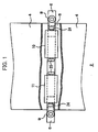
Fig. 1 is a plan view illustrating a main part of a conveyor with a partial cutout, according to an embodiment of the present invention; -
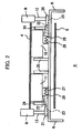
Fig. 2 is a vertical cross sectional] view of the main part of the conveyor according to the embodiment of the present invention; -
Fig. 3 is a view illustrating an operating state according to the embodiment of the present invention; and -
Fig. 4 is a vertical cross sectional] view of a main part of a conveyor according to a modification of the present invention. - Described below is a most preferred embodiment of the present invention.
-
Figs. 1 to 4 illustrate abelt conveyor 2 according to the embodiment and a modification thereof. Thebelt conveyor 2 includes anoutgoing belt 4 and a returningbelt 5, each made of steel, rubber, or the like. A steel belt is particularly suitable for the present invention, as the meandering steel belt raises a dangerous situation. In this specification, right and left each indicate a direction orthogonal to traveling directions of thebelts belts - There is provided a
frame 6 from right to left to be interposed between theoutgoing belt 4 and the returningbelt 5, and a pair ofdetection rollers outgoing belt 4. A pair of right andleft correction rollers outgoing belt 4.Support rods detection rollers left cams cam groove 22. Thecam groove 22 is inclined from a center down to the right or left end of theoutgoing belt 4. Thecams parts 23 provided on theframe 6. - Each of the
correction rollers post 25 around the center of theoutgoing belt 4, and is supported by apost 24 on the outer end of theoutgoing belt 4. Thecams outgoing belt 4 by biasingmembers outgoing belt 4 is located at a normal position, thedetection roller 8 is regulated by astopper 28 at a position not in contact with theoutgoing belt 4. - There are disposed, along the
belts frame 6 to thestopper 28. There are also disposed idler rollers, driving rollers, and the like between the meandering correctors. According to the present embodiment, each of thecams cam groove 22 to guide thepost 24. Alternatively, each of thecams post 24. Further alternatively, each of thecams frame 6. - Described below are operations according to the present embodiment. As exemplarily illustrated in
Fig. 3 , theoutgoing belt 4 meanders to left to slide theleft detection roller 9. Thecam 21 is then slid to left via thesupport rod 13 and thepost 24 is thus lifted up along thecam groove 22, so that thecorrection roller 11 is inclined from the outer end down to the center of the belt. The degree of inclination of thecorrection roller 11 is increased as theoutgoing belt 4 meanders more dramatically. Inclination of thecorrection roller 11 cancels meandering of theoutgoing belt 4. When the meandering is canceled, thecam 21 is returned to a normal position by thebiasing member 27 and is stopped by thestopper 28. -
Fig. 4 illustrates a modified meandering corrector. There are provided a pair of right andleft correction rollers belt 4. Each of the meandering correctors also includes four-joint links arms detection rollers joint links rotational axes belt 4 meanders and thedetection roller 9 is pressed by thebelt 4 to be rotated about therotational axis 48, thecorrection roller 41 is lifted up by the four-joint link 43 to cancel meandering of thebelt 4. When the meandering is canceled, thecorrection roller 41 is lifted by a biasingmember 50 down to a position not in contact with thebelt 4. It should be noted that theright correction roller 40 operates similarly to theleft correction roller 41.
While the present invention has been described with respect to preferred embodiments thereof, it will be apparent to those skilled in the art that the disclosed invention may be modified in numerous ways and may assume many embodiments other than those specifically set out and described above. Accordingly, the appended claims are intended to cover all modifications of the present invention that fall within the true spirit and scope of the present invention.
Claims (3)
- A belt conveyor comprising a corrector for a meandering belt, the meandering corrector including:a pair of right and left detection rollers which are disposed outside both outer ends in a width direction of the belt;at least a pair of right and left correction rollers which are disposed on right and left sides under the belt so as to be in contact with a rear face of the belt to correct the meandering belt; andinclining means for inclining, in a case where one of the right and left detection rollers is pressed by the belt, the correction roller disposed on one of right and left sides identical to the pressed detection roller such that the correction roller is inclined from the pressed detection roller down to a center of the belt.
- The belt conveyor according to claim 1, wherein the inclining means has:a pair of right and left cams each of which has a face inclined from the outer end down to the center of the belt and is shifted to right and left below the rear face of the belt in conjunction with the corresponding detection roller; andsupporting members which are lifted along the inclined faces of the cams and regulate levels of the correction rollers in right and left directions of the belt.
- The belt conveyor according to claim 2, further comprising:a frame which is disposed to be across from right to left below the rear face of the belt; anda pair of biasing members which bias the pair of cams toward the center of the belt, whereinthe pair of cams are attached to the frame so as to be slidable to right and left, andlower ends of support rods of the pair of detection rollers are attached respectively to the pair of right and left cams.
Applications Claiming Priority (1)
| Application Number | Priority Date | Filing Date | Title |
|---|---|---|---|
| JP2007340150A JP4458165B2 (en) | 2007-12-28 | 2007-12-28 | Conveyor |
Publications (1)
| Publication Number | Publication Date |
|---|---|
| EP2075206A1 true EP2075206A1 (en) | 2009-07-01 |
Family
ID=40276272
Family Applications (1)
| Application Number | Title | Priority Date | Filing Date |
|---|---|---|---|
| EP08020462A Withdrawn EP2075206A1 (en) | 2007-12-28 | 2008-11-25 | Conveyor |
Country Status (4)
| Country | Link |
|---|---|
| US (1) | US7686157B2 (en) |
| EP (1) | EP2075206A1 (en) |
| JP (1) | JP4458165B2 (en) |
| CN (1) | CN101468754A (en) |
Cited By (2)
| Publication number | Priority date | Publication date | Assignee | Title |
|---|---|---|---|---|
| DE102010002172A1 (en) * | 2010-02-22 | 2011-08-25 | Robert Bosch GmbH, 70469 | Device for controlling the directional stability of a belt |
| CN107672995A (en) * | 2017-09-06 | 2018-02-09 | 阜阳市风雅颂生产力促进中心有限责任公司 | Automatic deviation correcting device for belt transportation |
Families Citing this family (13)
| Publication number | Priority date | Publication date | Assignee | Title |
|---|---|---|---|---|
| KR101531622B1 (en) * | 2008-06-18 | 2015-06-26 | 삼성전자주식회사 | Image forming apparatus, fixing apparatus and belt assembly thereof |
| KR101355546B1 (en) * | 2012-01-31 | 2014-01-28 | 현대제철 주식회사 | Device for preventing deviation of belt conveyor |
| JP6048791B2 (en) * | 2012-07-03 | 2016-12-21 | 株式会社リコー | Belt control device, roller unit, and image forming apparatus |
| KR101348227B1 (en) | 2013-04-17 | 2014-01-07 | 황의상 | The two-way private swerving motion automatic adjustment device of the belt conveyor |
| KR101498894B1 (en) * | 2013-05-30 | 2015-03-05 | 현대제철 주식회사 | Jam-prevention apparatus of belt |
| CN103662716A (en) * | 2013-12-07 | 2014-03-26 | 衡阳运输机械有限公司 | Arc feeding rubber belt machine |
| US9061831B1 (en) * | 2013-12-18 | 2015-06-23 | Precision, Inc. | Conveyor belt aligning apparatus |
| WO2016094033A1 (en) * | 2014-12-09 | 2016-06-16 | Laitram, L.L.C. | Flexible-belt conveyor and methods of conveying |
| CN105966869B (en) * | 2016-07-08 | 2019-04-12 | 攀钢集团矿业有限公司 | Conveyer belt deviation correcting device, conveyer belt method for correcting error and belt conveyor |
| CN106586383A (en) * | 2016-12-02 | 2017-04-26 | 盐城市天辰新型建材有限公司 | Cement charging, transferring, conveying and collecting device |
| AU2019206004B2 (en) | 2018-07-16 | 2025-03-20 | Continental Global Material Handling Llc | Deflector for high angle conveyor pressing assembly |
| AU2019226160B2 (en) | 2018-09-05 | 2025-06-26 | Continental Global Material Handling Llc | High angle conveyor with self-adjusting inflection zone assembly |
| KR102813549B1 (en) * | 2023-01-20 | 2025-05-30 | 주식회사 에스에프에이 | System for goods transportation |
Citations (2)
| Publication number | Priority date | Publication date | Assignee | Title |
|---|---|---|---|---|
| US3973446A (en) * | 1973-10-17 | 1976-08-10 | Michael Vasilantone | Web aligner |
| JPH0920415A (en) * | 1995-07-06 | 1997-01-21 | Sumitomo Metal Ind Ltd | Water pressure type belt automatic centering device |
Family Cites Families (12)
| Publication number | Priority date | Publication date | Assignee | Title |
|---|---|---|---|---|
| US2239687A (en) * | 1939-07-06 | 1941-04-29 | Link Belt Co | Shock absorber for belt conveyer guide and actuating rolls |
| US3368665A (en) * | 1966-09-06 | 1968-02-13 | Alloy Wire Belt Co | Belt aligner |
| JPS6458517A (en) | 1987-08-29 | 1989-03-06 | Toyoda Gosei Kk | Method and apparatus for preparing cloth-containing rubber sheet |
| JPH04272042A (en) | 1991-02-27 | 1992-09-28 | Konica Corp | Belt meandering prevention device |
| JP2514516B2 (en) | 1992-02-05 | 1996-07-10 | タツタ電線株式会社 | Solderable conductive paste |
| JPH09175627A (en) | 1995-12-26 | 1997-07-08 | Nippon Conveyor Kk | Trough type roller for curve conveyor |
| NO305359B1 (en) * | 1996-05-31 | 1999-05-18 | Techno Track As | Belt control unit for centering conveyor belts, and method of controlling a conveyor belt when loading |
| SE507733C2 (en) * | 1996-11-01 | 1998-07-06 | Svedala Trellex Ab | Conveyor Control |
| DE29714416U1 (en) * | 1997-08-12 | 1997-11-06 | Transnorm System GmbH, 31177 Harsum | Belt steering station |
| US6390287B2 (en) * | 1999-06-10 | 2002-05-21 | The Robbins Company | Self-adjusting carrying idler assembly |
| JP2003176009A (en) | 2001-12-12 | 2003-06-24 | Nippon Conveyor Co Ltd | Meandering alignment device of belt for hanking roller |
| JP2006137588A (en) | 2004-11-15 | 2006-06-01 | Maruyasu Kikai Kk | Belt conveyor |
-
2007
- 2007-12-28 JP JP2007340150A patent/JP4458165B2/en not_active Expired - Fee Related
-
2008
- 2008-11-25 EP EP08020462A patent/EP2075206A1/en not_active Withdrawn
- 2008-12-09 US US12/331,191 patent/US7686157B2/en not_active Expired - Fee Related
- 2008-12-25 CN CNA2008101865323A patent/CN101468754A/en active Pending
Patent Citations (2)
| Publication number | Priority date | Publication date | Assignee | Title |
|---|---|---|---|---|
| US3973446A (en) * | 1973-10-17 | 1976-08-10 | Michael Vasilantone | Web aligner |
| JPH0920415A (en) * | 1995-07-06 | 1997-01-21 | Sumitomo Metal Ind Ltd | Water pressure type belt automatic centering device |
Cited By (2)
| Publication number | Priority date | Publication date | Assignee | Title |
|---|---|---|---|---|
| DE102010002172A1 (en) * | 2010-02-22 | 2011-08-25 | Robert Bosch GmbH, 70469 | Device for controlling the directional stability of a belt |
| CN107672995A (en) * | 2017-09-06 | 2018-02-09 | 阜阳市风雅颂生产力促进中心有限责任公司 | Automatic deviation correcting device for belt transportation |
Also Published As
| Publication number | Publication date |
|---|---|
| CN101468754A (en) | 2009-07-01 |
| US7686157B2 (en) | 2010-03-30 |
| US20090166159A1 (en) | 2009-07-02 |
| JP2009161279A (en) | 2009-07-23 |
| JP4458165B2 (en) | 2010-04-28 |
Similar Documents
| Publication | Publication Date | Title |
|---|---|---|
| US7686157B2 (en) | Conveyor | |
| CN108946094B (en) | Conveying device | |
| CN109689543B (en) | Transport system | |
| JP4849227B2 (en) | Automatic load position correction device | |
| KR101739454B1 (en) | Feeding apparatus for curvature forming of metal plate and method for feeding thereof | |
| US20170166402A1 (en) | Micro-transfer conveyor | |
| US20070232431A1 (en) | Power transmission chain, and power transmission system | |
| JP2008143208A (en) | Crawler travel device | |
| KR20130126537A (en) | Apparatus for wiring solar cell and conveying apparatus | |
| US8985554B2 (en) | System and method for lifting and lowering objects | |
| US7559548B2 (en) | Apparatus for the alignment of a stack of sheets | |
| JP2017178507A (en) | Belt meander adjustment device | |
| JP2012106845A (en) | Pallet position correcting device | |
| JP6726790B1 (en) | Transfer device and method for correcting meandering of belt of transfer device | |
| JP4289200B2 (en) | Transport equipment | |
| KR102773281B1 (en) | Apparatus to prevent moving for continuous ship unloader | |
| JP6964959B2 (en) | Transfer device | |
| JP2022108905A (en) | Carrier device including connection mechanism | |
| CN221057444U (en) | Cell piece righting mechanism | |
| KR101294904B1 (en) | Engine module mounting system of vehicle | |
| CN112173811B (en) | A floating wheel lifting mechanism | |
| JP2005255325A (en) | Seal belt device | |
| JP2009119529A (en) | Cable support device | |
| RU2482044C1 (en) | Belt conveyor intermediate linear drive | |
| JPH07228358A (en) | Guide roller support for bucket chain |
Legal Events
| Date | Code | Title | Description |
|---|---|---|---|
| PUAI | Public reference made under article 153(3) epc to a published international application that has entered the european phase |
Free format text: ORIGINAL CODE: 0009012 |
|
| AK | Designated contracting states |
Kind code of ref document: A1 Designated state(s): AT BE BG CH CY CZ DE DK EE ES FI FR GB GR HR HU IE IS IT LI LT LU LV MC MT NL NO PL PT RO SE SI SK TR |
|
| AX | Request for extension of the european patent |
Extension state: AL BA MK RS |
|
| AKX | Designation fees paid | ||
| STAA | Information on the status of an ep patent application or granted ep patent |
Free format text: STATUS: THE APPLICATION IS DEEMED TO BE WITHDRAWN |
|
| 18D | Application deemed to be withdrawn |
Effective date: 20100105 |
|
| REG | Reference to a national code |
Ref country code: DE Ref legal event code: 8566 |