EP2074977B1 - Transfer board for a person facilitating their movement between two sitting locations, in particular between a wheelchair and a chair - Google Patents
Transfer board for a person facilitating their movement between two sitting locations, in particular between a wheelchair and a chair Download PDFInfo
- Publication number
- EP2074977B1 EP2074977B1 EP08172953A EP08172953A EP2074977B1 EP 2074977 B1 EP2074977 B1 EP 2074977B1 EP 08172953 A EP08172953 A EP 08172953A EP 08172953 A EP08172953 A EP 08172953A EP 2074977 B1 EP2074977 B1 EP 2074977B1
- Authority
- EP
- European Patent Office
- Prior art keywords
- board
- panels
- transfer board
- rail
- joint
- Prior art date
- Legal status (The legal status is an assumption and is not a legal conclusion. Google has not performed a legal analysis and makes no representation as to the accuracy of the status listed.)
- Active
Links
- 238000006073 displacement reaction Methods 0.000 claims description 11
- 230000000903 blocking effect Effects 0.000 claims description 9
- 230000002787 reinforcement Effects 0.000 claims description 8
- 230000000295 complement effect Effects 0.000 claims description 4
- 230000003014 reinforcing effect Effects 0.000 description 10
- 208000031968 Cadaver Diseases 0.000 description 8
- 238000005728 strengthening Methods 0.000 description 3
- 241001080024 Telles Species 0.000 description 2
- 239000002184 metal Substances 0.000 description 2
- 229920000642 polymer Polymers 0.000 description 2
- 230000004224 protection Effects 0.000 description 2
- VVQNEPGJFQJSBK-UHFFFAOYSA-N Methyl methacrylate Chemical compound COC(=O)C(C)=C VVQNEPGJFQJSBK-UHFFFAOYSA-N 0.000 description 1
- 229920005372 Plexiglas® Polymers 0.000 description 1
- 238000004026 adhesive bonding Methods 0.000 description 1
- 238000013016 damping Methods 0.000 description 1
- 229920001971 elastomer Polymers 0.000 description 1
- 239000000806 elastomer Substances 0.000 description 1
- 230000005484 gravity Effects 0.000 description 1
- 239000003562 lightweight material Substances 0.000 description 1
- 239000000463 material Substances 0.000 description 1
- 230000003016 quadriplegic effect Effects 0.000 description 1
- 230000035939 shock Effects 0.000 description 1
- 239000002023 wood Substances 0.000 description 1
Images


Classifications
-
- A—HUMAN NECESSITIES
- A61—MEDICAL OR VETERINARY SCIENCE; HYGIENE
- A61G—TRANSPORT, PERSONAL CONVEYANCES, OR ACCOMMODATION SPECIALLY ADAPTED FOR PATIENTS OR DISABLED PERSONS; OPERATING TABLES OR CHAIRS; CHAIRS FOR DENTISTRY; FUNERAL DEVICES
- A61G7/00—Beds specially adapted for nursing; Devices for lifting patients or disabled persons
- A61G7/10—Devices for lifting patients or disabled persons, e.g. special adaptations of hoists thereto
- A61G7/1025—Lateral movement of patients, e.g. horizontal transfer
- A61G7/103—Transfer boards
-
- A—HUMAN NECESSITIES
- A61—MEDICAL OR VETERINARY SCIENCE; HYGIENE
- A61G—TRANSPORT, PERSONAL CONVEYANCES, OR ACCOMMODATION SPECIALLY ADAPTED FOR PATIENTS OR DISABLED PERSONS; OPERATING TABLES OR CHAIRS; CHAIRS FOR DENTISTRY; FUNERAL DEVICES
- A61G5/00—Chairs or personal conveyances specially adapted for patients or disabled persons, e.g. wheelchairs
- A61G5/10—Parts, details or accessories
Definitions
- the present invention relates to a transfer board for a person to facilitate its translation between two seated positions, in particular between a wheelchair and a seat, and more particularly between a wheelchair and a car seat.
- These boards are used as an object which is placed in abutment on these two seated positions so as to form a bridge between these two locations, in order to facilitate the autonomous translation in sitting position of disabled persons or persons with reduced mobility.
- the object of the invention relates more particularly to a transfer board for facilitating the transfer of a person from a sitting position on a support to another sitting position on another adjacent support. Even if such a transfer board was originally intended to allow the person to move between a wheelchair and an automobile seat, it should be understood that the object of the invention extends to any combination of seated supports. including chairs, beds, car seats and wheelchairs.
- a transfer board is described in the document GB 2,387,321 which has a transfer board consisting of at least two panels articulable with respect to each other at using a hinged hinge, so that one of the panels can fold over the other panels to reduce its volume for transport.
- this transfer board In order to allow the holding in extended position (or fully unfolded) of this transfer board and to prevent the board folds and falls at the time of passage of the person on the board, it is provided, inside hinge joint, locking means of the joint which allow to lock in position the hinge, which ensures a secure transfer of the person on the board.
- the hinge locking means of the hinge are relatively complex to implement and are difficult to manipulate by a person with little dexterity.
- the present invention proposes to solve the problems of the prior art using a transfer board for a person to facilitate its translation between two seated positions, the board comprising at least two panels capable of being articulated. relative to each other using a hinge-shaped hinge joint, so that one of the panels can be folded over the other of the panels thus defining a folded position of the board, means for strengthening the joint in the form of at least one movable member extending, in the extended or fully unfolded position of the board, on either side of the rotation axis hinged in the two panels, thanks to which the load of the person moving on the transfer board in the extended position is able to be distributed both on the joint and on the element, at least one rail being dug into the panels in which is able to move the element, characterized in that a flexible band is fixed in the rail of the element on either side of the hinge, whereby the element is held inside its rail in the folded position of the board .
- the element is able to move by sliding between a position in which it is fully housed in a complementary housing formed in only one of the panels of the board, and a position reinforcement in which it extends on either side of the axis of rotation in the two panels.
- the element comprises a projection adapted to come into contact against at least one stop provided on the path of movement of the element.
- the stop is in the form of a bridge crossing the rail.
- the element is a sliding bar.
- two sliding rails are provided which are substantially parallel to one another, in which two elements are respectively provided which are able to move and whose displacement is limited by at least stubborn.
- the plate according to the invention comprises means for blocking the displacement of the element, preferably in the position of reinforcing the articulation.
- the locking means are in the form of a movable projection provided on the path of movement of the element between a retracted position inside the panel and a projecting position.
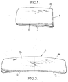
- the figure 1 represents a perspective view of a transfer board 1 for a person to facilitate its translation between two seated positions, preferably between a wheelchair and a car seat, the invention can of course be applied to any sitting position or any location on which a person may sit (such as a bed).
- the board 1 comprises at least two panels 2, 3 able to be articulated with respect to one another by means of a hinge forming an axis of rotation by hinges XX, so that one of the panels 2, 3 can be folded on the other of the panels 2, 3, thus facilitating its transport.
- the hinge XX constituted using at least one hinge (of known type), thus makes it possible to form a first folded position of the board 1 and a second completely unfolded or extended position of the board 1 (the board 1 then being substantially planar, see figure 2 ).
- Each panel 2, 3 has an upper face 2a, 3a and a lower face 2b, 3b. It is understood by “upper” face the face of the transfer board 1 on which is preferably able to slip the person during his passage from one location to another.
- This so-called upper face 2a is preferably smooth, substantially planar, and made of a material facilitating sliding, that is to say with a low coefficient of friction.
- FIG. 2 He is represented more precisely on the figure 2 an upper view of the transfer board 1 in its extended or fully unfolded position, that is to say in a view on the upper faces 2a, 3a of the panels 2, 3 of Plate 1.
- the Figures 5 to 7 represent, in turn, a perspective view of the lower faces 2b, 3b of the panels 2, 3 of the board 1 on which are provided means 5 for strengthening the joint XX.
- the means 5 for reinforcing the joint XX are in the form of at least one movable element 6, 7 extending, in fully unfolded position of the board 1, on either side of the axis of rotation.
- the board 1 in order to lighten the weight of the transfer board 1 and since the load of the person moving on the board 1 is mainly distributed on the reinforcing means 5, the board 1 can be made entirely of lightweight materials, such as only wood.
- the element 6, 7 is able to move by sliding between a position wherein the element 6, 7 is integrally housed in a complementary housing 6a, 7a formed in only one of the panels 2, 3 of the plate 1, and a position in which the element extends on both sides of the the axis of rotation XX in the two panels 2, 3.
- element 6, 7 is preferably in the form of a bar slider on which is fixed a projection 8 (for example by gluing or screwing) adapted to bear on at least one stop 9, 10 provided on the path of movement of the element 6, 7, so as to limit the displacement by sliding of this element 6, 7.
- the size and position of the projection 8 on the element 6, 7 is compatible with the location that can occupy the element 6, 7 in the respectively folded and extended positions of the board 1.
- the element 6, 7 may be of any shape (flat, H, 1 ). However, the most optimized form from the mechanical point of view is the I-section (eg IPN type metal profiles). On the other hand, a shape of the I-rail makes it possible to guarantee a higher security for the user during handling operations; there is indeed a lower probability of jamming his finger in the rail 11, 12, in which the element 6, 7 slides respectively.
- the projection 8 allows the user to manually move the element 6, 7 of reinforcement in the rail 11, 12, especially in case of inadvertent blocking.
- the shape of the projection 8 is preferably in a form adapted to a hand having little grip such as a quadriplegic hand.
- An anti-slip can also advantageously cover the projection 8 to facilitate gripping.
- the element 6, 7 is made rigid, that is to say it can be in the form of a metal bar, so as to stiffen the internal structure of the transfer board 1 in its extended position and thus achieve a strengthening structure of the joint XX when the board 1 is in its extended position (or fully unfolded) so that when a person slides on the upper face 2a, 3a of panels 2, 3 of the board 1, it is obtained a distribution of the forces exerted on the articulation XX at the level of this element 6, 7, so that the weight of the person is not only reflected on this joint XX but is also, or even essentially, spread over this or these elements 6,7.
- At least one rail 11, 12 is hollowed out in the lower surface 2b, 3b of the panels 2, 3 in which a respective element 6, 7 is slidably movable, the rail 11, 12 also forming the housing. 6a, 7a in which is housed the element 6, 7 in the folded position of the board 1.
- the transfer board 1 has two stops 9, 10 for limiting the displacement of the elements 6, 7 between the position allowing the folding and in which the elements 6, 7 are integrated in the panel 2 and do not exceed dimensions of this panel 2 (see figure 5 ), and a position in which the elements 6, 7 are located on either side of the hinge XX (see figure 7 ).
- the stops 9, 10 are in the form of a transverse bar fixed on the lower surface 2b, 3b of the panels 2, 3 forming a bridge through the rails 11,12 of the elements 6, 7.
- the projections 8 are then provided to abut against these bridges overhanging and crossing the rails 11, 12.
- the panels 2, 3 are of the same dimensions and are substantially symmetrical about the axis XX in the extended position of the boards 2, 3, that is to say in the substantially horizontal position, so that in folding position of a panel 2, 3 on the other panel 2, 3, then the bridge forming a stop 9 of one of the panels 2 is then in contact directly from the other abutment bridge 10 of the other of the panels 3. It is thus preferentially provided a stop 9, 10 on each panel 2, 3 on either side of the hinge XX.
- the element 6, 7 is limited in its displacement in the folded position of the board 1 by a flexible band 13 fixed in the rail 11, 12 of the element 6, 7 respectively on both sides of the joint XX, thanks to which the element 6, 7 is held inside its respective rail 11, 12 in the folded position of the board 1.
- the length and the stowage of the band 13 is set in such a way that it allows free movement of the element 6, 7 between the two extreme positions of the element 6, 7, that is to say between the position of the element 6, 7 in the housing 6a, 7a ( corresponding here to a part of the rail 11, 12) allowing the folding of the board 1 and the position of reinforcing the joint XX.
- this band 13 is not fixed or glued on any the length in the rail 11,12 but is simply fixed at specific points and limited in the rail 11, 12.
- the strip 13 is fixed only at its two ends inside the rail 11, 12.
- the locking means may thus be in the form of a latch adapted to cooperate with a recess formed in the projection 8 of the element 6, 7, this latch can be provided at the level of the folding position of the board 1, or at the position of reinforcing the joint XX so as to prevent its lateral sliding if the board is not substantially horizontal, that is to say at a placement transfer board 1 between two seated positions that are not at the same height.
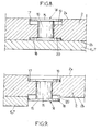
- FIGS. 8 and 9 are two sectional views of a preferred embodiment of the locking means 14 in position of the element 6, 7 respectively in an inactive position and in an active position.
- the locking means 14 may be in the form of a displaceable projection 15 provided on the path of movement of the element 6, 7 between a position retracted inside the panel 2, 3 ( figure 8 ) and a protruding position ( figure 9 ).
- the projection 15 is of the binding screw type, that is to say comprises a cylindrical central body 16 surrounded by a first transverse body 17 and a second transverse body 18.
- the transverse bodies 17, 18 are substantially planar bodies, it should be understood that it is also possible to realize convex transverse bodies, so that the first transverse body 17 is slightly protruding of the upper face 2a of the panel 2 or slightly tucked inside its respective housing 19.
- the second transverse body 18 it can be made in any suitable form, not just planar, so that it allows a blocking when it protrudes out of the lower face 2b of the panel 2 and a free passage of the element 6, 7 in its respective rail 11, 12 when it is in a retracted position in its respective housing 20.
- the projection 15 is advantageously placed in the rail 11, 12 at a location such that the projection 15 allows the locking in the reinforcing position of the element 6, 7 on both sides of the hinge XX while having the protrusion 8 of the element 6, 7 in contact on the stop 10 provided on the other panel 3 opposite the panel 2 in which the projection 15 is placed.
- the board 1 can be provided on the board 1 handles formed in the panels 2, 3 from through recesses made at the edge of the edges of the panels 2, 3, so that the user can insert his hands to the interior of these recesses, which allows him to better handle the board 1 and to have a better seat and a better stability during its transfer by sliding on the board 1.
- the fields of the board 1 can be covered with a polymer strip for damping shocks.
- protections for example visible, such as a transparent thin plate of plexiglass type (registered trademark)
- These protections are made in such a way that they prevent the user from getting their fingers caught in the rails 11, 12, while allowing access to the projections 8 provided on the elements 6, 7 reinforcement in case of inadvertent blocking (the user can in this case manually unlock the element 6, 7).
Landscapes
- Health & Medical Sciences (AREA)
- Veterinary Medicine (AREA)
- Life Sciences & Earth Sciences (AREA)
- Animal Behavior & Ethology (AREA)
- General Health & Medical Sciences (AREA)
- Public Health (AREA)
- Nursing (AREA)
- Steps, Ramps, And Handrails (AREA)
- Invalid Beds And Related Equipment (AREA)
- Special Chairs (AREA)
- Motorcycle And Bicycle Frame (AREA)
- Devices For Medical Bathing And Washing (AREA)
- Laminated Bodies (AREA)
- Mattresses And Other Support Structures For Chairs And Beds (AREA)
- Fittings On The Vehicle Exterior For Carrying Loads, And Devices For Holding Or Mounting Articles (AREA)
Abstract
Description
La présente invention porte sur une planche de transfert pour une personne permettant de faciliter sa translation entre deux emplacements assis, notamment entre un fauteuil roulant et un siège, et plus particulièrement entre un fauteuil roulant et un siège de voiture automobile.The present invention relates to a transfer board for a person to facilitate its translation between two seated positions, in particular between a wheelchair and a seat, and more particularly between a wheelchair and a car seat.
Ces planches sont utilisées comme un objet qui est placé en appui sur ces deux emplacements assis de manière à former un pont entre ces deux emplacements, ceci afin de faciliter la translation autonome en position assise des personnes handicapées ou à mobilité réduite.These boards are used as an object which is placed in abutment on these two seated positions so as to form a bridge between these two locations, in order to facilitate the autonomous translation in sitting position of disabled persons or persons with reduced mobility.
Il est connu à l'heure actuelle de réaliser de telles planches de transfert, voir par exemple le document
Ainsi, l'objet de l'invention porte plus particulièrement sur une planche de transfert permettant de faciliter le transfert d'une personne d'une position assise sur un support vers une autre position assise sur un autre support adjacent. Même si une telle planche de transfert a été initialement prévue pour permettre le déplacement de la personne entre un fauteuil roulant et un siège d'automobile, il doit être compris que l'objet de l'invention s'étend à toute combinaison de supports assis incluant notamment les chaises, les lits, les sièges de voiture et les fauteuils roulants.Thus, the object of the invention relates more particularly to a transfer board for facilitating the transfer of a person from a sitting position on a support to another sitting position on another adjacent support. Even if such a transfer board was originally intended to allow the person to move between a wheelchair and an automobile seat, it should be understood that the object of the invention extends to any combination of seated supports. including chairs, beds, car seats and wheelchairs.
Un exemple d'une telle forme de réalisation d'une planche de transfert est décrit dans le document
Un autre exemple d'un mode de réalisation d'une planche de transfert constituée d'un panneau central sur lequel sont respectivement fixés par articulations deux panneaux latéraux est également décrit dans le document
Il serait donc particulièrement intéressant de réaliser une planche de transfert facilement transportable, d'un poids léger, manipulable par des personnes ayant peu de dextérité et permettant de garantir un verrouillage simplifié de l'articulation de l'axe charnière.It would therefore be particularly advantageous to make a transfer board easily transportable, lightweight, manipulable by people with little dexterity and to ensure a simplified locking of the articulation of the hinge axis.
La présente invention se propose de résoudre les problèmes de l'art antérieur à l'aide d'une planche de transfert pour une personne permettant de faciliter sa translation entre deux emplacements assis, la planche comprenant au moins deux panneaux aptes à être articulés l'un par rapport à l'autre à l'aide d'une articulation formant un axe de rotation par charnière, de sorte qu'un des panneaux puisse se replier sur l'autre des panneaux définissant ainsi une position pliée de la planche, des moyens de renforcement de l'articulation sous la forme d'au moins un élément mobile s'étendant, en position étendue ou totalement dépliée de la planche, de part et d'autre de l'axe de rotation à charnière dans les deux panneaux, ce grâce à quoi la charge de la personne se déplaçant sur la planche de transfert en position étendue est apte à être répartie aussi bien sur l'articulation que sur l'élément, au moins un rail étant creusé dans les panneaux dans lequel est apte à se déplacer l'élément,
caractérisé en ce que une bande flexible est fixée dans le rail de l'élément de part et d'autre de l'articulation, ce grâce à quoi l'élément est maintenu à l'intérieur de son rail dans la position pliée de la planche.The present invention proposes to solve the problems of the prior art using a transfer board for a person to facilitate its translation between two seated positions, the board comprising at least two panels capable of being articulated. relative to each other using a hinge-shaped hinge joint, so that one of the panels can be folded over the other of the panels thus defining a folded position of the board, means for strengthening the joint in the form of at least one movable member extending, in the extended or fully unfolded position of the board, on either side of the rotation axis hinged in the two panels, thanks to which the load of the person moving on the transfer board in the extended position is able to be distributed both on the joint and on the element, at least one rail being dug into the panels in which is able to move the element,
characterized in that a flexible band is fixed in the rail of the element on either side of the hinge, whereby the element is held inside its rail in the folded position of the board .
Afin de permettre une manipulation minimale de la planche lors de son utilisation, l'élément est apte à se déplacer par coulissement entre une position dans laquelle il est intégralement logé dans un logement complémentaire formé dans un seul des panneaux de la planche, et une position de renforcement dans laquelle il s'étend de part et d'autre de l'axe de rotation dans les deux panneaux.In order to allow minimal handling of the board during its use, the element is able to move by sliding between a position in which it is fully housed in a complementary housing formed in only one of the panels of the board, and a position reinforcement in which it extends on either side of the axis of rotation in the two panels.
Afin de limiter le déplacement de l'élément dans la planche, l'élément comprend une saillie apte à venir en contact contre au moins une butée prévue sur le chemin de déplacement de l'élément.To limit the movement of the element in the board, the element comprises a projection adapted to come into contact against at least one stop provided on the path of movement of the element.
Avantageusement, la butée se présente sous la forme d'un pont traversant le rail.Advantageously, the stop is in the form of a bridge crossing the rail.
De manière avantageuse, l'élément est une barre coulissante.Advantageously, the element is a sliding bar.
Afin de permettre un renforcement équilibré de l'articulation, il est prévu deux rails de coulissement sensiblement parallèles l'un par rapport à l'autre, dans lesquels sont respectivement prévus deux éléments aptes à se déplacer et dont le déplacement est limité par au moins une butée.In order to allow a balanced reinforcement of the articulation, two sliding rails are provided which are substantially parallel to one another, in which two elements are respectively provided which are able to move and whose displacement is limited by at least stubborn.
Afin de verrouiller le mouvement de rotation de l'articulation, la planche selon l'invention comprend des moyens de blocage du déplacement de l'élément, préférentiellement dans la position de renforcement de l'articulation.In order to lock the rotational movement of the articulation, the plate according to the invention comprises means for blocking the displacement of the element, preferably in the position of reinforcing the articulation.
Selon une forme de réalisation avantageuse, les moyens de blocage se présentent sous la forme d'une saillie déplaçable prévue sur le chemin de déplacement de l'élément entre une position rentrée à l'intérieur du panneau et une position en saillie.According to an advantageous embodiment, the locking means are in the form of a movable projection provided on the path of movement of the element between a retracted position inside the panel and a projecting position.
La présente invention est maintenant décrite à l'aide d'un exemple uniquement illustratif et nullement limitatif de la portée de la présente invention, et à partir des illustrations suivantes dans lesquelles :
- la
figure 1 est une vue en perspective d'une forme de réalisation de la planche de transfert selon l'invention dans son état plié ; - la
figure 2 est une vue en perspective de la face supérieure de la planche de transfert dans sa position étendue ou totalement dépliée, face sur laquelle est apte à glisser une personne entre deux emplacements assis; - la
figure 3 est une vue en perspective de la planche de transfert dans l'état plié, et plus précisément de son articulation formant axe charnière ; - la
figure 4 est une vue en perspective agrandie de l'articulation de la planche selon l'invention au moment de son pliage ; - les
figures 5 à 7 représentent trois vues en perspective de la face inférieure de la planche de transfert dans laquelle sont prévus des moyens de renforcement de l'articulation aptes à coulisser entre une première position, telle que représentée à lafigure 4 et dans laquelle le pliage de la planche est autorisé, et une position de renforcement de l'articulation telle qu'illustrée à lafigure 7 et dans laquelle la charge de la personne se déplaçant sur la face supérieure de la planche de transfert est apte à être répartie aussi bien sur l'articulation que sur les moyens de renforcement ; - les
figures 8 sont deux vues en coupe à travers une forme de réalisation de moyens de blocage en position de l'élément coulissant respectivement dans une position inactive et dans une position active.et 9
- the
figure 1 is a perspective view of an embodiment of the transfer board according to the invention in its folded state; - the
figure 2 is a perspective view of the upper face of the transfer board in its extended or fully unfolded position, on which side is able to slide a person between two seated positions; - the
figure 3 is a perspective view of the transfer board in the folded state, and more precisely of its articulation hinge axis; - the
figure 4 is an enlarged perspective view of the articulation of the board according to the invention at the time of its folding; - the
Figures 5 to 7 represent three perspective views of the lower face of the transfer board in which there are provided means for reinforcing the hinge slidable between a first position, as shown in FIG.figure 4 and in which the folding of the board is allowed, and a position of reinforcing the hinge as illustrated in FIG.figure 7 and in which the load of the person moving on the upper face of the board of transfer is able to be distributed both on the articulation and on the reinforcement means; - the
Figures 8 and 9 are two sectional views through an embodiment of locking means in position of the sliding member respectively in an inactive position and in an active position.
La
La planche 1 comprend au moins deux panneaux 2, 3 aptes à être articulés l'un par rapport à l'autre à l'aide d'une articulation formant un axe de rotation par charnières X-X, de sorte qu'un des panneaux 2, 3 puisse se replier sur l'autre des panneaux 2, 3, facilitant ainsi son transport. L'articulation X-X, constituée à l'aide d'au moins une charnière (de type connu en soi), permet donc de former une première position pliée de la planche 1 et une seconde position totalement dépliée ou étendue de la planche 1 (la planche 1 étant alors sensiblement planaire, voir
Chaque panneau 2, 3 présente une face supérieure 2a, 3a ainsi qu'une face inférieure 2b, 3b. Il est entendu par face « supérieure » la face de la planche de transfert 1 sur laquelle est préférentiellement apte à glisser la personne lors de son passage d'un emplacement assis à un autre. Cette face dite supérieure 2a est donc préférentiellement lisse, sensiblement planaire, et réalisée dans un matériau facilitant le glissage, c'est-à-dire à faible coefficient de frottement.Each
Il est représenté plus précisément sur la
Les moyens de renforcement 5 de l'articulation X-X se présentent sous la forme d'au moins un élément mobile 6, 7 s'étendant, en position totalement dépliée de la planche 1, de part et d'autre de l'axe de rotation X-X à charnière dans les deux panneaux 2,3, ce grâce à quoi la charge de la personne se déplaçant sur la planche de transfert 1 est apte à être répartie aussi bien sur l'articulation X-X que sur l'élément 6, 7.The
Préférentiellement, afin d'alléger le poids de la planche de transfert 1 et puisque la charge de la personne se déplaçant sur la planche 1 est principalement répartie sur les moyens de renforcement 5, la planche 1 peut être entièrement réalisée en des matériaux légers, tels que du bois.Preferably, in order to lighten the weight of the transfer board 1 and since the load of the person moving on the board 1 is mainly distributed on the
Toutefois, bien qu'il soit représenté sur les figures le mode de réalisation préférentiel de l'invention dans lequel l'élément mobile 6, 7 n'est pas prévu amovible de la planche 1, il est également possible de prévoir une planche 1 dans laquelle l'élément mobile 6, 7 est un élément indépendant de la planche 1.However, although it is shown in the figures the preferred embodiment of the invention in which the
Cependant, afin d'éviter la perte de cet élément mobile 6, 7 et d'augmenter les manipulations nécessaires pour le montage de la planche 1 en position totalement dépliée, l'élément 6, 7 est apte à se déplacer par coulissement entre une position dans laquelle l'élément 6, 7 est intégralement logé dans un logement 6a, 7a complémentaire formé dans un seul des panneaux 2, 3 de la planche 1, et une position dans laquelle l'élément s'étend de part et d'autre de l'axe de rotation X-X dans les deux panneaux 2, 3.However, in order to avoid the loss of this
De manière plus précise et comme cela est représenté sur les figures, l'élément 6, 7 se présente préférentiellement sous la forme d'une barre coulissante sur laquelle est fixée une saillie 8 (par exemple par collage ou par vissage) apte à venir en appui sur au moins une butée 9, 10 prévue sur le chemin de déplacement de l'élément 6, 7, de sorte à limiter le déplacement par coulissement de cet élément 6, 7. La taille et la position de la saillie 8 sur l'élément 6, 7 est compatible avec l'emplacement que peut occuper l'élément 6, 7 dans les positions respectivement pliée et étendue de la planche 1.More precisely and as shown in the figures,
L'élément 6, 7 peut être de forme quelconque (plate, en H, en 1...). Cependant, la forme la plus optimisée du point de vue mécanique est le profilé en I (pair exemple les profilés métalliques de type IPN). D'autre part, une forme du rail en I permet de garantir une sécurité plus élevée pour l'utilisateur lors des opérations de manipulations ; il existe en effet une probabilité moins élevée de coincer son doigt dans le rail 11, 12, dans lequel coulisse respectivement l'élément 6, 7.The
En plus du rôle de butée, la saillie 8 permet à l'utilisateur de bouger manuellement l'élément 6, 7 de renfort dans le rail 11, 12, surtout en cas de blocage intempestif. La forme de la saillie 8 se présente préférentiellement sous une forme adaptée à une main ayant peu de préhension telle qu'une main de tétraplégique. Un anti-dérapant peut également avantageusement couvrir la saillie 8 pour en faciliter la préhension.In addition to the role of abutment, the
Bien qu'il soit représenté sur les figures un mode de réalisation de la planche de transfert 1 avec deux éléments coulissants 6, 7 prévus dans la face inférieure 2b, 3b des panneaux 2, 3 de la planche 1, il est bien entendu qu'il est également possible de réaliser une telle planche 1 avec un seul élément 6, 7 ou avec plus de deux éléments 6, 7. De même, le principe général de l'invention peut s'appliquer également à une planche 1 avec plus de deux panneaux 2, 3.Although it is shown in the figures an embodiment of the transfer board 1 with two sliding
L'élément 6, 7 est réalisé rigide, c'est-à-dire qu'il peut se présenter sous la forme d'une barre métallique, de manière à rigidifier la structure interne de la planche de transfert 1 dans sa position étendue et ainsi réaliser une structure de renforcement de l'articulation X-X quand la planche 1 est dans sa position étendue (ou totalement dépliée) de sorte que, quand une personne glisse sur la face supérieure 2a, 3a des panneaux 2, 3 de la planche 1, il est obtenu une répartition des efforts exercés sur l'articulation X-X au niveau de cet élément 6, 7, de sorte que le poids de la personne n'est pas uniquement répercuté sur cette articulation X-X mais est également, voire essentiellement répartie sur ce ou ces éléments 6,7.The
Plus précisément, au moins un rail 11, 12 est creusé dans la surface inférieure 2b, 3b des panneaux 2, 3 dans lequel est apte à se déplacer par coulissement un élément 6, 7 respectif, le rail 11,12 formant alors également le logement 6a, 7a dans lequel est logé l'élément 6, 7 en position pliée de la planche 1.More precisely, at least one
Selon le mode de représentation illustré sur les figures, la planche de transfert 1 présente deux butées 9, 10 permettant de borner le déplacement des éléments 6, 7 entre la position permettant le pliage et dans laquelle les éléments 6, 7 sont intégrés dans le panneau 2 et ne dépassent pas des dimensions de ce panneau 2 (voir
Pour ce faire, les butées 9, 10 se présentent sous la forme d'une barre transversale fixée sur la surface inférieure 2b, 3b des panneaux 2, 3 formant un pont traversant les rails 11,12 des éléments 6, 7. Les saillies 8 sont alors prévues pour venir en butée contre ces ponts surplombant et traversant les rails 11, 12.To do this, the
Avantageusement, les panneaux 2, 3 sont de mêmes dimensions et sont sensiblement symétriques par rapport à l'axe X-X dans la position étendue des planches 2, 3, c'est-à-dire dans la position sensiblement horizontale, de sorte qu'en position de pliage d'un panneau 2, 3 sur l'autre panneau 2, 3, alors le pont formant butée 9 de l'un des panneaux 2 est alors en contact direct de l'autre pont formant butée 10 de l'autre des panneaux 3. Il est ainsi préférentiellement prévu une butée 9, 10 sur chaque panneau 2, 3 de part et d'autre de l'articulation X-X.Advantageously, the
Il peut être remarqué que, selon le mode de réalisation préférentiel de la planche 1, il est prévu deux rails de coulissement 11, 12 sensiblement parallèles l'un par rapport à l'autre dans lesquels sont respectivement prévus deux éléments 6, 7 sous la forme de barres coulissantes et dont le déplacement est limité par les butées 9, 10, tout en sachant qu'il est également possible de prévoir que le déplacement de ces éléments 6, 7 soit limité par une seule butée et de prévoir à la place d'une butée des moyens d'accrochage de la barre coulissante empêchant ainsi son coulissement.It may be noted that, according to the preferred embodiment of the board 1, there are provided two sliding
Préférentiellement, l'élément 6, 7 est limité dans ses déplacement en position pliée de la planche 1 par une bande 13 flexible fixée dans le rail 11, 12 de l'élément 6, 7 respectif de part et d'autre de l'articulation X-X, ce grâce à quoi l'élément 6, 7 est maintenu à l'intérieur de son rail 11,12 respectif dans la position pliée de la planche 1. La longueur et l'arrimage de la bande 13 est paramétrée de manière telle qu'elle permet le déplacement libre de l'élément 6, 7 entre les deux positions extrêmes de l'élément 6, 7, c'est-à-dire entre la position de l'élément 6, 7 dans le logement 6a, 7a (correspondant ici en une partie du rail 11, 12) permettant le pliage de la planche 1 et la position de renforcement de l'articulation X-X. Sans la présence de cette bande 13, il existerait un risque que l'élément 6, 7 ne reste pas dans le logement 6a, 7a du rail 11, 12 quand la planche 1 est pliée, du fait de la présence d'un intervalle i entre les deux panneaux 2, 3 pliés l'un sur l'autre (voir
Il peut être prévu des moyens de blocage du déplacement des éléments 6, 7, préférentiellement dans la position de renforcement l'articulation X-X. A titre d'exemple, les moyens de blocage peuvent ainsi se présenter sous la forme d'un loquet apte à coopérer avec un évidement formé dans la saillie 8 de l'élément 6, 7, ce loquet pouvant être prévu soit au niveau de la position de pliage de la planche 1, soit au niveau de la position de renforcement de l'articulation X-X de manière à empêcher son coulissement latéral si la planche n'est pas sensiblement horizontale, c'est-à-dire lors d'un placement de la planche de transfert 1 entre deux emplacements assis qui ne sont pas à une même hauteur.It can be provided means for blocking the displacement of the
Alternativement, il peut être également prévu des moyens aimantés, c'est-à-dire de prévoir un ou plusieurs aimants sur l'élément 6, 7 et un ou plusieurs aimants de polarité opposée sur au moins l'un des panneaux 2, 3 de la planche 1 de manière à permettre son blocage, soit en position de pliage de la planche, soit en position de renforcement de l'articulation X-X de la planche 1.Alternatively, it may also be provided magnetic means, that is to say to provide one or more magnets on the
De manière alternative il peut être également prévu un système du type à bande velcro (marque déposée) ou tout autre système approprié.Alternatively it may also be provided a system type Velcro (trademark) or any other suitable system.
Les
Ainsi, les moyens de blocage 14 peuvent se présenter sous la forme d'une saillie 15 déplaçable prévue sur le chemin de déplacement de l'élément 6, 7 entre une position rentrée à l'intérieur du panneau 2, 3 (
Selon une forme de réalisation préférentielle, mais non exclusive, la saillie 15 est du type vis de reliure, c'est-à-dire comprend un corps central cylindrique 16 entouré par un premier corps transversal 17 et un second corps transversal 18.According to a preferred embodiment, but not exclusively, the
Préférentiellement, les premier et second corps transversaux 17, 18 sont logés dans des logements respectifs 19, 20 de forme complémentaire dans lesquels les corps transversaux 17, 18 présentent un déplacement relatif, de sorte que :
- dans la position inactive de la saillie 15, le
premier corps transversal 17 est au même niveau que laface supérieure 2a du panneau 2 et lesecond corps transversal 18 est au même niveau que laface inférieure 2b du panneau 2, ce grâce à quoi l'élément 6, 7 peut se déplacer librement dansson rail respectif - dans la position active de la saillie 15, le
premier corps transversal 17 est enfoncé dans son logement 19 respectif à l'intérieur du panneau 2, ce qui entraîne la mise en saillie dusecond corps transversal 18 hors dela face inférieure 2b du panneau 2, ce grâce à quoi l'élément 6, 7 ne peut plus se déplacer dansson rail respectif premier corps transversal 17 dans son logement respectif 19 est réalisée soit par gravité, soit par l'utilisateur de la planche 1 qui a alors exercé une force de poussée sur lepremier corps transversal 17 de manière à permettre le coulissement du corps central 16 et la mise en saillie dusecond corps transversal 18.
- in the inactive position of the
projection 15, the firsttransverse body 17 is at the same level as theupper face 2a of thepanel 2 and the secondtransverse body 18 is at the same level as thelower face 2b of thepanel 2, thanks to which theelement respective rail - in the active position of the
projection 15, the firsttransverse body 17 is pressed into itsrespective housing 19 inside thepanel 2, which causes the projection of the secondtransverse body 18 out of thelower face 2b of thepanel 2 thanks to which theelement respective rail transverse body 17 in itsrespective housing 19 is carried out either by gravity or by the user of the board 1 which then exerted a thrust force on the firsttransverse body 17 so as to allow the sliding of thecentral body 16 and the projecting of the secondtransverse body 18.
Bien que dans le mode de réalisation illustré, les corps transversaux 17, 18 sont des corps sensiblement planaires, il doit être compris qu'il est également possible de réaliser des corps transversaux bombés, de sorte que le premier corps transversal 17 soit légèrement en saillie de la face supérieure 2a du panneau 2 ou alors légèrement rentré à l'intérieur de son logement respectif 19. Quant au second corps transversal 18, il peut être réalisé selon toute forme appropriée, et pas uniquement planaire, de sorte qu'il permet un blocage quand il est en saillie hors de la face inférieure 2b du panneau 2 et un libre passage de l'élément 6, 7 dans son rail respectif 11,12 quand il est dans une position rentrée dans son logement respectif 20.Although in the illustrated embodiment, the
La saillie 15 est avantageusement placée dans le rail 11, 12 à un emplacement tel que la saillie 15 permet le blocage en position de renforcement de l'élément 6, 7 de part et d'autre de l'articulation X-X tout en ayant la saillie 8 de l'élément 6, 7 en contact sur la butée 10 prévue sur l'autre panneau 3 opposé au panneau 2 dans lequel est placée la saillie 15.The
De manière supplémentaire, il peut être prévu sur la planche 1 des poignées formées dans les panneaux 2, 3 à partir d'évidements traversants réalisées à la limite des bords des panneaux 2, 3, de sorte que l'utilisateur puisse insérer ses mains à l'intérieur de ces évidements, ce qui lui permet de mieux manipuler la planche 1 et d'avoir une meilleure assise et une meilleure stabilité lors de son transfert par glissement sur la planche 1.In addition, it can be provided on the board 1 handles formed in the
Par ailleurs, afin d'éviter que la chute de la planche 1 ne blesse l'utilisateur ou un tiers, les champs de la planche 1 peuvent être recouverts d'une bande de polymère permettant d'amortir les chocs.Moreover, to prevent the fall of the board 1 does not hurt the user or a third party, the fields of the board 1 can be covered with a polymer strip for damping shocks.
De plus, afin de limiter les risques de glissement de la planche 1 en position étendue lors de son placement en appui entre deux emplacement assis pour ainsi permettre la translation en position assise des personnes à mobilité réduite, il est prévu d'incorporer des plaques de polymère antidérapant (typiquement des élastomères) au niveau des extrémités de la planche 1 qui sont en appui sur ces emplacements (ces plaques antidérapantes peuvent être directement intégrées dans la surface inférieure 2b, 3b de la planche 1).In addition, in order to limit the risk of sliding of the board 1 in the extended position when placed in support between two seated position so as to allow the translation in sitting position of people with reduced mobility, it is planned to incorporate plates of non-slip polymer (typically elastomers) at the ends of the board 1 which are supported on these locations (these anti-slip plates can be directly integrated into the
Par ailleurs, afin d'éviter que l'utilisateur ne se blesse lors de l'opération de dépliage ou pliage de la planche 1, des protections (par exemple visibles, telle qu'une plaque fine transparente de type plexiglas (marque déposée)) seront mises sur les rails 11, 12. Ces protections sont réalisées de manière telle qu'elles empêchent à l'utilisateur de se coincer les doigts dans les rails 11, 12, tout en lui laissant accès aux saillies 8 prévues sur les éléments 6, 7 de renfort en cas de blocage intempestif (l'utilisateur pouvant dans ce cas débloquer manuellement l'élément 6, 7).Moreover, in order to prevent the user from getting injured during the unfolding or folding operation of the board 1, protections (for example visible, such as a transparent thin plate of plexiglass type (registered trademark)) will be put on the
Claims (8)
- Transfer board (1) for a person facilitating their translation between two sitting locations, said board (1) comprising at least two panels (2, 3) able to be articulated in relation to one another using a joint (X-X) forming an axis of rotation per hinge, in such a way that one of the panels (2, 3) can fold over the other of the panels (2, 3) thus defining a folded position of the board (1), means of reinforcement (5) of said joint (X-X) in the form of at least one mobile element (6, 7) extending, in the extended or entirely unfolded position of the board (1), on either side of the axis of rotation with hinge (X-X) in the two panels (2, 3), this thanks to which the load of the person moving on the transfer board (1) in extended position is able to be distributed on said joint (X-X) as well as on said element (6, 7), at least one rail (11, 12) being gouged (in said panels (2, 3) wherein is able to be displaced said element (6, 7), characterised in that a flexible strip (13) is fixed in said rail (11, 12) of said element (6, 7) on either side of said joint (X-X), this thanks to which said element (6, 7) is maintained inside its respective rail (11, 12) in the folded position of the board (1).
- Transfer board according to claim 1, characterised in that said element (6, 7) is able to be displaced by sliding between:- a position wherein said element (6, 7) is fully housed in a complementary housing (6a, 7a) formed in a single one of the panels (2, 3) of the board (1), and- a position of reinforcement wherein said element (6, 7) extends on either side of the axis of rotation (X-X) in the two panels (2, 3).
- Transfer board according to any of the preceding claims, characterised in that said element (6, 7) comprises a protrusion (8) able to come into contact against at least one abutment (9, 10) provided on the displacement path of said element (6, 7).
- Transfer board according to claim 3, characterised in that said abutment (9, 10) has the form of a bridge crossing said rail (11, 12).
- Transfer board according to any of the preceding claims, characterised in that said element (6, 7) is a sliding bar.
- Transfer board according to any of the preceding claims, characterised in that it is provided with two sliding rails (11, 12) substantially parallel to one another, wherein are respectively provided two elements (6, 7) able to be displaced and of which the displacement is limited by at least one abutment (9, 10).
- Transfer board according to any of the preceding claims, characterised in that it comprises means of blocking (14) the displacement of said element (6, 7), preferentially in said position of reinforcement of said joint (X-X).
- Transfer board according to claim 7, characterised in that said means of blocking (14) have the form of a protrusion (15) which can be displaced provided on the displacement path of said element (6, 7) between a retracted position inside a panel (2, 3) and a protruding position.
Priority Applications (1)
| Application Number | Priority Date | Filing Date | Title |
|---|---|---|---|
| PL08172953T PL2074977T3 (en) | 2007-12-28 | 2008-12-26 | Transfer board for a person facilitating their movement between two sitting locations, in particular between a wheelchair and a chair |
Applications Claiming Priority (1)
| Application Number | Priority Date | Filing Date | Title |
|---|---|---|---|
| FR0760427A FR2925843B1 (en) | 2007-12-28 | 2007-12-28 | TRANSFER BOARD FOR A PERSON TO FACILITATE ITS TRANSLATION BETWEEN TWO SITTED LOCATIONS, IN PARTICULAR BETWEEN A WHEELCHAIR AND A SEAT |
Publications (2)
| Publication Number | Publication Date |
|---|---|
| EP2074977A1 EP2074977A1 (en) | 2009-07-01 |
| EP2074977B1 true EP2074977B1 (en) | 2011-03-23 |
Family
ID=39689100
Family Applications (1)
| Application Number | Title | Priority Date | Filing Date |
|---|---|---|---|
| EP08172953A Active EP2074977B1 (en) | 2007-12-28 | 2008-12-26 | Transfer board for a person facilitating their movement between two sitting locations, in particular between a wheelchair and a chair |
Country Status (6)
| Country | Link |
|---|---|
| EP (1) | EP2074977B1 (en) |
| AT (1) | ATE502615T1 (en) |
| DE (1) | DE602008005698D1 (en) |
| ES (1) | ES2363184T3 (en) |
| FR (1) | FR2925843B1 (en) |
| PL (1) | PL2074977T3 (en) |
Families Citing this family (3)
| Publication number | Priority date | Publication date | Assignee | Title |
|---|---|---|---|---|
| US9629770B1 (en) * | 2011-12-19 | 2017-04-25 | Joseph T. Dyer | Portable transfer board and method |
| US20150190297A1 (en) * | 2014-01-07 | 2015-07-09 | Arun Rajagopal | Arm support apparatus for prone patients |
| CN115414214B (en) * | 2022-09-06 | 2023-09-26 | 中国人民解放军总医院第五医学中心 | Multifunctional liver-penetrating wheelchair bed for children |
Family Cites Families (5)
| Publication number | Priority date | Publication date | Assignee | Title |
|---|---|---|---|---|
| US4700416A (en) * | 1986-02-18 | 1987-10-20 | Johansson Paul J | Patient transfer mat |
| JPH09234166A (en) * | 1996-02-29 | 1997-09-09 | Toto Ltd | Bathroom unit |
| CA2250548A1 (en) * | 1998-10-27 | 2000-04-27 | Antonio Ditommaso | Collapsible transfer bench |
| GB2387321B (en) * | 2002-04-10 | 2004-04-14 | Roozbeh Shirandami | Disabled transfer board |
| GB0417453D0 (en) | 2004-08-05 | 2004-09-08 | Mangar Int Ltd | Device for assisting disabled and elderly persons |
-
2007
- 2007-12-28 FR FR0760427A patent/FR2925843B1/en not_active Expired - Fee Related
-
2008
- 2008-12-26 PL PL08172953T patent/PL2074977T3/en unknown
- 2008-12-26 ES ES08172953T patent/ES2363184T3/en active Active
- 2008-12-26 AT AT08172953T patent/ATE502615T1/en not_active IP Right Cessation
- 2008-12-26 EP EP08172953A patent/EP2074977B1/en active Active
- 2008-12-26 DE DE602008005698T patent/DE602008005698D1/en active Active
Also Published As
| Publication number | Publication date |
|---|---|
| FR2925843A1 (en) | 2009-07-03 |
| ATE502615T1 (en) | 2011-04-15 |
| FR2925843B1 (en) | 2011-01-14 |
| DE602008005698D1 (en) | 2011-05-05 |
| ES2363184T3 (en) | 2011-07-26 |
| PL2074977T3 (en) | 2011-09-30 |
| EP2074977A1 (en) | 2009-07-01 |
Similar Documents
| Publication | Publication Date | Title |
|---|---|---|
| FR2920209A1 (en) | WEIGHT SUSPENSION HOOK | |
| FR2972990A1 (en) | STROLLER CHASSIS FOR CHILDREN WITH TWO FOLD POSITIONS AND CORRESPONDING STROLLER | |
| FR2853824A1 (en) | FOLDABLE BABY SEAT | |
| FR3023160A1 (en) | ARTICULATED ARMCHAIR COMPRISING A VERTICALIZATION MECHANISM FOR A ROLLING VEHICLE. | |
| EP2074977B1 (en) | Transfer board for a person facilitating their movement between two sitting locations, in particular between a wheelchair and a chair | |
| EP0279753A1 (en) | Conference easel | |
| EP3141152B1 (en) | A removable table with a reduced bulk, in particular for a railway vehicle | |
| FR2732938A1 (en) | COMBINATION OF A TROLLEY AND A REMOVABLE ELEMENT AND REMOVABLE ELEMENT FOR TROLLEY | |
| EP3398808B1 (en) | Rotary seat with raisable footrest, in particular for railway vehicle | |
| FR2948265A1 (en) | Towable hand luggage, has retractable support system for moving between folded position and deployed position, and two parallel uprights including intermediate portion, which is integrated into box | |
| WO2009027353A2 (en) | Convertible hammock stroller and corresponding hammock | |
| FR2834431A1 (en) | Suitcase has extending seat supported by tubular leg attached to one end of case and by rectangular frame on opposite end of seat | |
| EP1679018B1 (en) | Table top | |
| WO1994020309A1 (en) | Adaptable shopping list support | |
| WO2005065514A1 (en) | Toilet seat | |
| FR3054519A1 (en) | WHEELED / FOLDABLE WHEEL VEHICLE, IN PARTICULAR OF TROTTINETTE TYPE | |
| FR2948559A1 (en) | Foldable wheelchair for use by person with reduced mobility in sports field, has rear wheels mounted on chair structure in removable manner, and seat including backrest folded against base | |
| FR3050638A1 (en) | TABLET SYSTEM FOR WHEELCHAIR, AND WHEELCHAIR EQUIPPED WITH SUCH A SYSTEM | |
| EP1941813A1 (en) | Slatted topsurface and table equipped with a topsurface as indicated | |
| FR2762978A1 (en) | Low multi-purpose folding table | |
| EP0808593A2 (en) | High chair with variable configuration | |
| WO2020183085A1 (en) | Base for furniture | |
| FR3028175A1 (en) | EMBITABLE MEDICAL TRANSFER CHAIR | |
| EP1942770B1 (en) | Double seat that conceals baggage | |
| EP1530928A1 (en) | Collapsible chair seat with a low profile in the collapsed position |
Legal Events
| Date | Code | Title | Description |
|---|---|---|---|
| PUAI | Public reference made under article 153(3) epc to a published international application that has entered the european phase |
Free format text: ORIGINAL CODE: 0009012 |
|
| AK | Designated contracting states |
Kind code of ref document: A1 Designated state(s): AT BE BG CH CY CZ DE DK EE ES FI FR GB GR HR HU IE IS IT LI LT LU LV MC MT NL NO PL PT RO SE SI SK TR |
|
| AX | Request for extension of the european patent |
Extension state: AL BA MK RS |
|
| 17P | Request for examination filed |
Effective date: 20091027 |
|
| AKX | Designation fees paid |
Designated state(s): AT BE BG CH CY CZ DE DK EE ES FI FR GB GR HR HU IE IS IT LI LT LU LV MC MT NL NO PL PT RO SE SI SK TR |
|
| GRAP | Despatch of communication of intention to grant a patent |
Free format text: ORIGINAL CODE: EPIDOSNIGR1 |
|
| GRAS | Grant fee paid |
Free format text: ORIGINAL CODE: EPIDOSNIGR3 |
|
| GRAA | (expected) grant |
Free format text: ORIGINAL CODE: 0009210 |
|
| AK | Designated contracting states |
Kind code of ref document: B1 Designated state(s): AT BE BG CH CY CZ DE DK EE ES FI FR GB GR HR HU IE IS IT LI LT LU LV MC MT NL NO PL PT RO SE SI SK TR |
|
| REG | Reference to a national code |
Ref country code: GB Ref legal event code: FG4D Free format text: NOT ENGLISH |
|
| REG | Reference to a national code |
Ref country code: CH Ref legal event code: EP |
|
| REG | Reference to a national code |
Ref country code: IE Ref legal event code: FG4D |
|
| REF | Corresponds to: |
Ref document number: 602008005698 Country of ref document: DE Date of ref document: 20110505 Kind code of ref document: P |
|
| REG | Reference to a national code |
Ref country code: DE Ref legal event code: R096 Ref document number: 602008005698 Country of ref document: DE Effective date: 20110505 |
|
| REG | Reference to a national code |
Ref country code: NL Ref legal event code: VDEP Effective date: 20110323 |
|
| REG | Reference to a national code |
Ref country code: ES Ref legal event code: FG2A Ref document number: 2363184 Country of ref document: ES Kind code of ref document: T3 Effective date: 20110726 |
|
| PG25 | Lapsed in a contracting state [announced via postgrant information from national office to epo] |
Ref country code: SE Free format text: LAPSE BECAUSE OF FAILURE TO SUBMIT A TRANSLATION OF THE DESCRIPTION OR TO PAY THE FEE WITHIN THE PRESCRIBED TIME-LIMIT Effective date: 20110323 Ref country code: LT Free format text: LAPSE BECAUSE OF FAILURE TO SUBMIT A TRANSLATION OF THE DESCRIPTION OR TO PAY THE FEE WITHIN THE PRESCRIBED TIME-LIMIT Effective date: 20110323 Ref country code: HR Free format text: LAPSE BECAUSE OF FAILURE TO SUBMIT A TRANSLATION OF THE DESCRIPTION OR TO PAY THE FEE WITHIN THE PRESCRIBED TIME-LIMIT Effective date: 20110323 Ref country code: GR Free format text: LAPSE BECAUSE OF FAILURE TO SUBMIT A TRANSLATION OF THE DESCRIPTION OR TO PAY THE FEE WITHIN THE PRESCRIBED TIME-LIMIT Effective date: 20110624 Ref country code: LV Free format text: LAPSE BECAUSE OF FAILURE TO SUBMIT A TRANSLATION OF THE DESCRIPTION OR TO PAY THE FEE WITHIN THE PRESCRIBED TIME-LIMIT Effective date: 20110323 |
|
| LTIE | Lt: invalidation of european patent or patent extension |
Effective date: 20110323 |
|
| PG25 | Lapsed in a contracting state [announced via postgrant information from national office to epo] |
Ref country code: SI Free format text: LAPSE BECAUSE OF FAILURE TO SUBMIT A TRANSLATION OF THE DESCRIPTION OR TO PAY THE FEE WITHIN THE PRESCRIBED TIME-LIMIT Effective date: 20110323 Ref country code: NO Free format text: LAPSE BECAUSE OF FAILURE TO SUBMIT A TRANSLATION OF THE DESCRIPTION OR TO PAY THE FEE WITHIN THE PRESCRIBED TIME-LIMIT Effective date: 20110623 Ref country code: CY Free format text: LAPSE BECAUSE OF FAILURE TO SUBMIT A TRANSLATION OF THE DESCRIPTION OR TO PAY THE FEE WITHIN THE PRESCRIBED TIME-LIMIT Effective date: 20110323 Ref country code: BG Free format text: LAPSE BECAUSE OF FAILURE TO SUBMIT A TRANSLATION OF THE DESCRIPTION OR TO PAY THE FEE WITHIN THE PRESCRIBED TIME-LIMIT Effective date: 20110623 Ref country code: AT Free format text: LAPSE BECAUSE OF FAILURE TO SUBMIT A TRANSLATION OF THE DESCRIPTION OR TO PAY THE FEE WITHIN THE PRESCRIBED TIME-LIMIT Effective date: 20110323 Ref country code: FI Free format text: LAPSE BECAUSE OF FAILURE TO SUBMIT A TRANSLATION OF THE DESCRIPTION OR TO PAY THE FEE WITHIN THE PRESCRIBED TIME-LIMIT Effective date: 20110323 |
|
| REG | Reference to a national code |
Ref country code: PL Ref legal event code: T3 |
|
| REG | Reference to a national code |
Ref country code: IE Ref legal event code: FD4D |
|
| PG25 | Lapsed in a contracting state [announced via postgrant information from national office to epo] |
Ref country code: PT Free format text: LAPSE BECAUSE OF FAILURE TO SUBMIT A TRANSLATION OF THE DESCRIPTION OR TO PAY THE FEE WITHIN THE PRESCRIBED TIME-LIMIT Effective date: 20110725 Ref country code: EE Free format text: LAPSE BECAUSE OF FAILURE TO SUBMIT A TRANSLATION OF THE DESCRIPTION OR TO PAY THE FEE WITHIN THE PRESCRIBED TIME-LIMIT Effective date: 20110323 |
|
| PG25 | Lapsed in a contracting state [announced via postgrant information from national office to epo] |
Ref country code: RO Free format text: LAPSE BECAUSE OF FAILURE TO SUBMIT A TRANSLATION OF THE DESCRIPTION OR TO PAY THE FEE WITHIN THE PRESCRIBED TIME-LIMIT Effective date: 20110323 Ref country code: IS Free format text: LAPSE BECAUSE OF FAILURE TO SUBMIT A TRANSLATION OF THE DESCRIPTION OR TO PAY THE FEE WITHIN THE PRESCRIBED TIME-LIMIT Effective date: 20110723 Ref country code: SK Free format text: LAPSE BECAUSE OF FAILURE TO SUBMIT A TRANSLATION OF THE DESCRIPTION OR TO PAY THE FEE WITHIN THE PRESCRIBED TIME-LIMIT Effective date: 20110323 Ref country code: CZ Free format text: LAPSE BECAUSE OF FAILURE TO SUBMIT A TRANSLATION OF THE DESCRIPTION OR TO PAY THE FEE WITHIN THE PRESCRIBED TIME-LIMIT Effective date: 20110323 |
|
| PG25 | Lapsed in a contracting state [announced via postgrant information from national office to epo] |
Ref country code: NL Free format text: LAPSE BECAUSE OF FAILURE TO SUBMIT A TRANSLATION OF THE DESCRIPTION OR TO PAY THE FEE WITHIN THE PRESCRIBED TIME-LIMIT Effective date: 20110323 |
|
| PLBE | No opposition filed within time limit |
Free format text: ORIGINAL CODE: 0009261 |
|
| STAA | Information on the status of an ep patent application or granted ep patent |
Free format text: STATUS: NO OPPOSITION FILED WITHIN TIME LIMIT |
|
| PG25 | Lapsed in a contracting state [announced via postgrant information from national office to epo] |
Ref country code: IE Free format text: LAPSE BECAUSE OF FAILURE TO SUBMIT A TRANSLATION OF THE DESCRIPTION OR TO PAY THE FEE WITHIN THE PRESCRIBED TIME-LIMIT Effective date: 20110323 |
|
| 26N | No opposition filed |
Effective date: 20111227 |
|
| PG25 | Lapsed in a contracting state [announced via postgrant information from national office to epo] |
Ref country code: DK Free format text: LAPSE BECAUSE OF FAILURE TO SUBMIT A TRANSLATION OF THE DESCRIPTION OR TO PAY THE FEE WITHIN THE PRESCRIBED TIME-LIMIT Effective date: 20110323 |
|
| REG | Reference to a national code |
Ref country code: DE Ref legal event code: R097 Ref document number: 602008005698 Country of ref document: DE Effective date: 20111227 |
|
| PG25 | Lapsed in a contracting state [announced via postgrant information from national office to epo] |
Ref country code: MC Free format text: LAPSE BECAUSE OF NON-PAYMENT OF DUE FEES Effective date: 20111231 |
|
| REG | Reference to a national code |
Ref country code: DE Ref legal event code: R119 Ref document number: 602008005698 Country of ref document: DE Effective date: 20120703 |
|
| PG25 | Lapsed in a contracting state [announced via postgrant information from national office to epo] |
Ref country code: DE Free format text: LAPSE BECAUSE OF NON-PAYMENT OF DUE FEES Effective date: 20120703 |
|
| PG25 | Lapsed in a contracting state [announced via postgrant information from national office to epo] |
Ref country code: MT Free format text: LAPSE BECAUSE OF FAILURE TO SUBMIT A TRANSLATION OF THE DESCRIPTION OR TO PAY THE FEE WITHIN THE PRESCRIBED TIME-LIMIT Effective date: 20110323 |
|
| PG25 | Lapsed in a contracting state [announced via postgrant information from national office to epo] |
Ref country code: LU Free format text: LAPSE BECAUSE OF NON-PAYMENT OF DUE FEES Effective date: 20111226 |
|
| REG | Reference to a national code |
Ref country code: CH Ref legal event code: PL |
|
| PG25 | Lapsed in a contracting state [announced via postgrant information from national office to epo] |
Ref country code: TR Free format text: LAPSE BECAUSE OF FAILURE TO SUBMIT A TRANSLATION OF THE DESCRIPTION OR TO PAY THE FEE WITHIN THE PRESCRIBED TIME-LIMIT Effective date: 20110323 |
|
| PG25 | Lapsed in a contracting state [announced via postgrant information from national office to epo] |
Ref country code: HU Free format text: LAPSE BECAUSE OF FAILURE TO SUBMIT A TRANSLATION OF THE DESCRIPTION OR TO PAY THE FEE WITHIN THE PRESCRIBED TIME-LIMIT Effective date: 20110323 Ref country code: CH Free format text: LAPSE BECAUSE OF NON-PAYMENT OF DUE FEES Effective date: 20121231 Ref country code: LI Free format text: LAPSE BECAUSE OF NON-PAYMENT OF DUE FEES Effective date: 20121231 |
|
| REG | Reference to a national code |
Ref country code: FR Ref legal event code: PLFP Year of fee payment: 8 |
|
| REG | Reference to a national code |
Ref country code: FR Ref legal event code: PLFP Year of fee payment: 9 |
|
| REG | Reference to a national code |
Ref country code: FR Ref legal event code: PLFP Year of fee payment: 10 |
|
| PGFP | Annual fee paid to national office [announced via postgrant information from national office to epo] |
Ref country code: PL Payment date: 20201127 Year of fee payment: 13 |
|
| PGFP | Annual fee paid to national office [announced via postgrant information from national office to epo] |
Ref country code: ES Payment date: 20210107 Year of fee payment: 13 |
|
| PGFP | Annual fee paid to national office [announced via postgrant information from national office to epo] |
Ref country code: GB Payment date: 20221219 Year of fee payment: 15 Ref country code: FR Payment date: 20221121 Year of fee payment: 15 |
|
| REG | Reference to a national code |
Ref country code: ES Ref legal event code: FD2A Effective date: 20230302 |
|
| PG25 | Lapsed in a contracting state [announced via postgrant information from national office to epo] |
Ref country code: ES Free format text: LAPSE BECAUSE OF NON-PAYMENT OF DUE FEES Effective date: 20211227 |
|
| PG25 | Lapsed in a contracting state [announced via postgrant information from national office to epo] |
Ref country code: PL Free format text: LAPSE BECAUSE OF NON-PAYMENT OF DUE FEES Effective date: 20211226 |
|
| PGFP | Annual fee paid to national office [announced via postgrant information from national office to epo] |
Ref country code: IT Payment date: 20221209 Year of fee payment: 15 |
|
| P01 | Opt-out of the competence of the unified patent court (upc) registered |
Effective date: 20231024 |
|
| PGFP | Annual fee paid to national office [announced via postgrant information from national office to epo] |
Ref country code: BE Payment date: 20231212 Year of fee payment: 16 |
|
| GBPC | Gb: european patent ceased through non-payment of renewal fee |
Effective date: 20231226 |