EP2074948A1 - Ultrasound system for diagnosing breast cancer - Google Patents
Ultrasound system for diagnosing breast cancer Download PDFInfo
- Publication number
- EP2074948A1 EP2074948A1 EP08022484A EP08022484A EP2074948A1 EP 2074948 A1 EP2074948 A1 EP 2074948A1 EP 08022484 A EP08022484 A EP 08022484A EP 08022484 A EP08022484 A EP 08022484A EP 2074948 A1 EP2074948 A1 EP 2074948A1
- Authority
- EP
- European Patent Office
- Prior art keywords
- array transducer
- ultrasound
- ultrasound system
- elements
- receive
- Prior art date
- Legal status (The legal status is an assumption and is not a legal conclusion. Google has not performed a legal analysis and makes no representation as to the accuracy of the status listed.)
- Withdrawn
Links
Images



Classifications
-
- A—HUMAN NECESSITIES
- A61—MEDICAL OR VETERINARY SCIENCE; HYGIENE
- A61B—DIAGNOSIS; SURGERY; IDENTIFICATION
- A61B8/00—Diagnosis using ultrasonic, sonic or infrasonic waves
- A61B8/08—Clinical applications
- A61B8/0825—Clinical applications for diagnosis of the breast, e.g. mammography
-
- A—HUMAN NECESSITIES
- A61—MEDICAL OR VETERINARY SCIENCE; HYGIENE
- A61B—DIAGNOSIS; SURGERY; IDENTIFICATION
- A61B8/00—Diagnosis using ultrasonic, sonic or infrasonic waves
- A61B8/48—Diagnostic techniques
- A61B8/483—Diagnostic techniques involving the acquisition of a 3D volume of data
-
- A—HUMAN NECESSITIES
- A61—MEDICAL OR VETERINARY SCIENCE; HYGIENE
- A61B—DIAGNOSIS; SURGERY; IDENTIFICATION
- A61B8/00—Diagnosis using ultrasonic, sonic or infrasonic waves
- A61B8/48—Diagnostic techniques
- A61B8/485—Diagnostic techniques involving measuring strain or elastic properties
Definitions
- the present invention generally relates to ultrasound systems, and more particularly to an ultrasound system adopting an ultrasound probe for diagnosing breast cancers.
- breast cancers are a significant medical concern for women.
- the breast cancers significantly increase the mortality rate of women and also lead to severe psychological/emotional trauma as well as economic loss.
- preventing breast tumors and conducting regular periodic medical examinations to find such tumors at an early stage are very important.
- a breast cancer diagnostic apparatus that uses X-rays for performing early diagnosis of breast tumors.
- the conventional breast cancer diagnostic apparatus may press the patient's breast with about 20 kg load, the patient feels severe pain. Also, it may be difficult for the patient to maintain a stationary posture due to such pain. As such, accurate images may not be obtained.
- an ultrasound system has been used to provide elastic images for diagnosing breast tumors based on the stress applied through a probe.
- the patent still feels much pain since the elastic images are provided while pressing the breast.
- FIG. 1 is a perspective view showing one embodiment of an ultrasound probe.
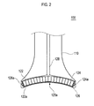
- FIG. 2 is a cross-sectional view showing one embodiment of an ultrasound probe.
- FIG. 3 is a schematic diagram showing an example of rotating an array transducer.
- FIG. 4 is a block diagram showing an illustrative embodiment of an ultrasound system with an ultrasound probe having an array transducer with an arcuate shape.
- FIG. 5 is a schematic diagram showing an example of scan lines originated from elements of an array transducer.
- FIG. 1 is a perspective view showing one embodiment of an ultrasound probe.
- the ultrasound probe 100 may include a grip portion 110, an ultrasound transmitting/receiving portion 120 and a cable 130 connected to a body (not shown).
- the grip portion 110 may be formed to have a trumpet shape. This is so that an easy and stable grip may be provided and an end of the grip portion 110 may be coupled to the ultrasound transmitting/receiving portion 120.
- the grip portion 110 may not be limited to such a shape. That is, the grip portion 110 may be formed in various shapes according to necessity.
- the ultrasound transmitting/receiving portion 120 may be formed to have a cylindrical shape.
- the ultrasound transmitting/receiving portion 120 may include a probing surface 120a of a concave shape at a bottom side thereof for contacting the surface of a target object.
- FIG. 2 is a cross-sectional view schematically showing one embodiment of the ultrasound probe 100.
- the ultrasound transmitting/receiving portion 120 may include an array transducer 122.
- the array transducer 122 may include a plurality of elements 122a, which are arrayed in a longitudinal direction to have an arcuate shape.
- a front side of the array transducer 122 i.e., a concave portion thereof, may face the probing surface 120a.
- Lubricant oil may be filled between the array transducer 122 and the probing surface 120a.
- the plurality of elements 122a may be configured to generate ultrasound signals. Also, the elements 122a may further convert ultrasound signals reflected from the target object into electrical receive signals.
- the ultrasound transmitting/receiving portion 120 may further include a supporting part 124 surrounding the array transducer 122 for support.
- the support part 124 may include projecting parts 124a at both end sides of the array transducer 122.
- the projecting parts 124a may be formed to have various shapes such as a rectangle, triangle, trapezoid and the like.
- the supporting part 124 may further include a backing layer for protecting the ultrasound signals generated from the elements 122a from being transmitted backward.
- the ultrasound transmitting/receiving portion 120 may further include a guiding part 126 for guiding the array transducer 122.
- the guiding part 126 may be formed to have a circular shape.
- the guiding part 126 may include a guide rail 126a formed in a circumference direction at an inner surface of the guiding part 126 for receiving the projecting parts 124a and guiding the movements of the projecting parts 124a.
- the ultrasound transmitting/receiving portion 120 may further include a driving motor (not shown) and a rotating shaft 128 connected to the driving motor.
- the rotating shaft 128 may be fixed to a center of the array transducer 122 by the supporting part 124.
- the rotating shaft 128 may transfer a power of the motor to the array transducer 122 such that the array transducer 122 is rotated in the guiding part 126 along the guide rail 126a, as shown in FIG. 3 .
- the array transducer 122 may transmit the ultrasound signals while the probing surface 120a is in contact with the surface of the target object (especially the breast).
- FIG. 4 is a block diagram showing an ultrasound system adopting one embodiment of the ultrasound probe.
- the ultrasound system 400 may include a control unit 410, a transmission/reception unit 420, an image processing unit 430 and a display unit 440.
- the control unit 410 may be configured to generate control signals for controlling the driving motor in the ultrasound probe 110 for rotating the array transducer 122 at a predetermined angle range as well as the transmission/reception of the ultrasound signals at the elements 122a of the array transducer 122.
- the control unit 410 may generate a first control signal for controlling the driving motor such that the array transducer 122 may be rotated within 180 degrees.
- the control unit 410 may generate a second control signal for the transmission and reception of the ultrasound signals. Since the array transducer 122 is formed to have an arcuate shape in one embodiment, the control unit 410 control angles of scan lines originated from the elements 122a such that the scan lines are set in parallel, as illustrated in FIG. 5 .
- the transmission/reception unit 420 may be configured to generate transmit pulse signals in consideration of distances between the respective elements 122a and focal points set on the scan lines in the target object in response to the second control signal.
- the transmit pulse signals may be applied to the elements 122a through the cable 130.
- the transmission/reception unit 420 may perform receive focusing upon receive signals outputted from the array transducer 122 in consideration of distances between the respective elements 122a and the focal points, thereby outputting receive-focused beams.
- the receive focused beams may be obtained while the array transducer 122 is rotated.
- the image processing unit 430 may be configured to perform image processing upon the focused beams to form a 3-dimensional ultrasound image.
- the display unit 440 may display the 3-dimensional ultrasound image of the target object.
- a breast image may be obtained without feeling pain caused by pressure. Also, since the ultrasound signals are transmitted and received while the array transducer is rotated at a predetermined angle range in a horizontal direction to the surface of the target object, a 3-dimensional ultrasound image may be provided.
- an ultrasound system comprising: an ultrasound probe including an array transducer having an arcuate shape, the array transducer containing a plurality of elements arrayed in a longitudinal direction of the array transducer; and a probing surface for contacting a surface of the target object, wherein the probing surface is formed to have a concave shape at a front side of the array transducer.
- any reference in this specification to "one embodiment,” “an embodiment,” “example embodiment,” etc. means that a particular feature, structure or characteristic described in connection with the embodiment is included in at least one embodiment of the present invention.
- the appearances of such phrases in various places in the specification are not necessarily all referring to the same embodiment.
Landscapes
- Life Sciences & Earth Sciences (AREA)
- Health & Medical Sciences (AREA)
- Biomedical Technology (AREA)
- Biophysics (AREA)
- Nuclear Medicine, Radiotherapy & Molecular Imaging (AREA)
- Pathology (AREA)
- Radiology & Medical Imaging (AREA)
- Engineering & Computer Science (AREA)
- Physics & Mathematics (AREA)
- Heart & Thoracic Surgery (AREA)
- Medical Informatics (AREA)
- Molecular Biology (AREA)
- Surgery (AREA)
- Animal Behavior & Ethology (AREA)
- General Health & Medical Sciences (AREA)
- Public Health (AREA)
- Veterinary Medicine (AREA)
- Ultra Sonic Daignosis Equipment (AREA)
Abstract
Description
- The present application claims priority from Korean Patent Application Nos.
10-2007-0138430 10-2008-0132601 - The present invention generally relates to ultrasound systems, and more particularly to an ultrasound system adopting an ultrasound probe for diagnosing breast cancers.
- Breast cancers are a significant medical concern for women. The breast cancers significantly increase the mortality rate of women and also lead to severe psychological/emotional trauma as well as economic loss. Thus, preventing breast tumors and conducting regular periodic medical examinations to find such tumors at an early stage are very important. As such, there has been introduced a breast cancer diagnostic apparatus that uses X-rays for performing early diagnosis of breast tumors.
- However, since the conventional breast cancer diagnostic apparatus may press the patient's breast with about 20 kg load, the patient feels severe pain. Also, it may be difficult for the patient to maintain a stationary posture due to such pain. As such, accurate images may not be obtained.
- Recently, in order to address and resolve the above-mentioned problems, an ultrasound system has been used to provide elastic images for diagnosing breast tumors based on the stress applied through a probe. However, the patent still feels much pain since the elastic images are provided while pressing the breast.
-
FIG. 1 is a perspective view showing one embodiment of an ultrasound probe. -
FIG. 2 is a cross-sectional view showing one embodiment of an ultrasound probe. -
FIG. 3 is a schematic diagram showing an example of rotating an array transducer. -
FIG. 4 is a block diagram showing an illustrative embodiment of an ultrasound system with an ultrasound probe having an array transducer with an arcuate shape. -
FIG. 5 is a schematic diagram showing an example of scan lines originated from elements of an array transducer. -
FIG. 1 is a perspective view showing one embodiment of an ultrasound probe. As shown inFIG. 1 , theultrasound probe 100 may include agrip portion 110, an ultrasound transmitting/receivingportion 120 and acable 130 connected to a body (not shown). Thegrip portion 110 may be formed to have a trumpet shape. This is so that an easy and stable grip may be provided and an end of thegrip portion 110 may be coupled to the ultrasound transmitting/receivingportion 120. However, thegrip portion 110 may not be limited to such a shape. That is, thegrip portion 110 may be formed in various shapes according to necessity. The ultrasound transmitting/receivingportion 120 may be formed to have a cylindrical shape. The ultrasound transmitting/receivingportion 120 may include aprobing surface 120a of a concave shape at a bottom side thereof for contacting the surface of a target object. -
FIG. 2 is a cross-sectional view schematically showing one embodiment of theultrasound probe 100. The ultrasound transmitting/receivingportion 120 may include anarray transducer 122. Thearray transducer 122 may include a plurality ofelements 122a, which are arrayed in a longitudinal direction to have an arcuate shape. A front side of thearray transducer 122, i.e., a concave portion thereof, may face theprobing surface 120a. Lubricant oil may be filled between thearray transducer 122 and theprobing surface 120a. The plurality ofelements 122a may be configured to generate ultrasound signals. Also, theelements 122a may further convert ultrasound signals reflected from the target object into electrical receive signals. The ultrasound transmitting/receivingportion 120 may further include a supportingpart 124 surrounding thearray transducer 122 for support. Thesupport part 124 may include projectingparts 124a at both end sides of thearray transducer 122. The projectingparts 124a may be formed to have various shapes such as a rectangle, triangle, trapezoid and the like. The supportingpart 124 may further include a backing layer for protecting the ultrasound signals generated from theelements 122a from being transmitted backward. - The ultrasound transmitting/receiving
portion 120 may further include a guidingpart 126 for guiding thearray transducer 122. The guidingpart 126 may be formed to have a circular shape. The guidingpart 126 may include aguide rail 126a formed in a circumference direction at an inner surface of the guidingpart 126 for receiving the projectingparts 124a and guiding the movements of the projectingparts 124a. The ultrasound transmitting/receivingportion 120 may further include a driving motor (not shown) and a rotatingshaft 128 connected to the driving motor. Therotating shaft 128 may be fixed to a center of thearray transducer 122 by the supportingpart 124. The rotatingshaft 128 may transfer a power of the motor to thearray transducer 122 such that thearray transducer 122 is rotated in theguiding part 126 along theguide rail 126a, as shown inFIG. 3 . Thearray transducer 122 may transmit the ultrasound signals while theprobing surface 120a is in contact with the surface of the target object (especially the breast). -
FIG. 4 is a block diagram showing an ultrasound system adopting one embodiment of the ultrasound probe. Theultrasound system 400 may include acontrol unit 410, a transmission/reception unit 420, animage processing unit 430 and adisplay unit 440. Thecontrol unit 410 may be configured to generate control signals for controlling the driving motor in theultrasound probe 110 for rotating thearray transducer 122 at a predetermined angle range as well as the transmission/reception of the ultrasound signals at theelements 122a of thearray transducer 122. In one embodiment, thecontrol unit 410 may generate a first control signal for controlling the driving motor such that thearray transducer 122 may be rotated within 180 degrees. Thecontrol unit 410 may generate a second control signal for the transmission and reception of the ultrasound signals. Since thearray transducer 122 is formed to have an arcuate shape in one embodiment, thecontrol unit 410 control angles of scan lines originated from theelements 122a such that the scan lines are set in parallel, as illustrated inFIG. 5 . - The transmission/
reception unit 420 may be configured to generate transmit pulse signals in consideration of distances between therespective elements 122a and focal points set on the scan lines in the target object in response to the second control signal. The transmit pulse signals may be applied to theelements 122a through thecable 130. Also, the transmission/reception unit 420 may perform receive focusing upon receive signals outputted from thearray transducer 122 in consideration of distances between therespective elements 122a and the focal points, thereby outputting receive-focused beams. The receive focused beams may be obtained while thearray transducer 122 is rotated. - The
image processing unit 430 may be configured to perform image processing upon the focused beams to form a 3-dimensional ultrasound image. Thedisplay unit 440 may display the 3-dimensional ultrasound image of the target object. - As the
probing surface 120a and thearray transducer 122 in theultrasound probe 100 are formed to have an arcuate shape, a breast image may be obtained without feeling pain caused by pressure. Also, since the ultrasound signals are transmitted and received while the array transducer is rotated at a predetermined angle range in a horizontal direction to the surface of the target object, a 3-dimensional ultrasound image may be provided. - In accordance with one embodiment of the present invention, there is provided an ultrasound system, comprising: an ultrasound probe including an array transducer having an arcuate shape, the array transducer containing a plurality of elements arrayed in a longitudinal direction of the array transducer; and a probing surface for contacting a surface of the target object, wherein the probing surface is formed to have a concave shape at a front side of the array transducer.
- Any reference in this specification to "one embodiment," "an embodiment," "example embodiment," etc. means that a particular feature, structure or characteristic described in connection with the embodiment is included in at least one embodiment of the present invention. The appearances of such phrases in various places in the specification are not necessarily all referring to the same embodiment. Further, when a particular feature, structure or characteristic is described in connection with any embodiment, it is submitted that it is within the purview of one skilled in the art to effect such feature, structure or characteristic in connection with other ones of the embodiments.
- Although embodiments have been described with reference to a number of illustrative embodiments thereof, it should be understood that numerous other modifications and embodiments can be devised by those skilled in the art that will fall within the spirit and scope of the principles of this disclosure. More particularly, numerous variations and modifications are possible in the component parts and/or arrangements of the subject combination arrangement within the scope of the disclosure, the drawings and the appended claims. In addition to variations and modifications in the component parts and/or arrangements, alternative uses will also be apparent to those skilled in the art.
Claims (5)
- An ultrasound system, comprising:an ultrasound probe including an array transducer having an arcuate shape, the array transducer containing a plurality of elements arrayed in a longitudinal direction of the array transducer, the ultrasound probe further including a probing surface for contacting a surface of a target object, wherein the probing surface is formed to have a concave shape at a front side of the array transducer.
- The ultrasound system of Claim 1, wherein the ultrasound probe further includes:a guiding part having a cylindrical shape for guiding a rotation of the array transducer in a circumference direction at an inter surface of the guiding part ; anda driving unit configured to rotate the array transducer in the guiding part.
- The ultrasound system of Claim 2, wherein the driving unit includes:a driving motor configured to provide a power; anda rotating shaft connected to the driving motor and the array transducer for transferring the power to the array transducer for the rotation.
- The ultrasound system of Claim 3, further comprising:a control unit configured to generate a first control signal for controlling transmission/reception of ultrasound signals at the array transducer and a second control signal for controlling the driving motor for the rotation of the array transducer;a transmission/reception unit configured to generate transmit pulse signals in consideration of distances between the elements and focal points and perform receive-focusing the receive signals to thereby output receive-focused beams; andan image processing unit configured to form a 3-dimensional image based on the receive focused beams.
- The ultrasound system of Claim 4, wherein the control unit is further configured to control angles of scan lines originated from the elements.
Applications Claiming Priority (2)
| Application Number | Priority Date | Filing Date | Title |
|---|---|---|---|
| KR20070138430 | 2007-12-27 | ||
| KR1020080132601A KR20090071424A (en) | 2007-12-27 | 2008-12-23 | Ultrasound System for Breast Cancer Diagnosis |
Publications (1)
| Publication Number | Publication Date |
|---|---|
| EP2074948A1 true EP2074948A1 (en) | 2009-07-01 |
Family
ID=40409841
Family Applications (1)
| Application Number | Title | Priority Date | Filing Date |
|---|---|---|---|
| EP08022484A Withdrawn EP2074948A1 (en) | 2007-12-27 | 2008-12-29 | Ultrasound system for diagnosing breast cancer |
Country Status (3)
| Country | Link |
|---|---|
| US (1) | US20090171217A1 (en) |
| EP (1) | EP2074948A1 (en) |
| JP (1) | JP2009153980A (en) |
Cited By (1)
| Publication number | Priority date | Publication date | Assignee | Title |
|---|---|---|---|---|
| FR3142339A1 (en) | 2022-11-30 | 2024-05-31 | Echopen Factory | VERSATILE ULTRASOUND PROBE WITH MULTIPLE SINGLE-ELEMENT TRANSDUCERS WITH OSCILLATING MECHANICAL SCANNING |
Families Citing this family (43)
| Publication number | Priority date | Publication date | Assignee | Title |
|---|---|---|---|---|
| US8784336B2 (en) | 2005-08-24 | 2014-07-22 | C. R. Bard, Inc. | Stylet apparatuses and methods of manufacture |
| US8388546B2 (en) | 2006-10-23 | 2013-03-05 | Bard Access Systems, Inc. | Method of locating the tip of a central venous catheter |
| US7794407B2 (en) | 2006-10-23 | 2010-09-14 | Bard Access Systems, Inc. | Method of locating the tip of a central venous catheter |
| US10449330B2 (en) | 2007-11-26 | 2019-10-22 | C. R. Bard, Inc. | Magnetic element-equipped needle assemblies |
| US8781555B2 (en) | 2007-11-26 | 2014-07-15 | C. R. Bard, Inc. | System for placement of a catheter including a signal-generating stylet |
| US8849382B2 (en) | 2007-11-26 | 2014-09-30 | C. R. Bard, Inc. | Apparatus and display methods relating to intravascular placement of a catheter |
| ES2557084T3 (en) | 2007-11-26 | 2016-01-21 | C. R. Bard, Inc. | Integrated system for intravascular catheter placement |
| US10751509B2 (en) | 2007-11-26 | 2020-08-25 | C. R. Bard, Inc. | Iconic representations for guidance of an indwelling medical device |
| US9492097B2 (en) | 2007-11-26 | 2016-11-15 | C. R. Bard, Inc. | Needle length determination and calibration for insertion guidance system |
| US9521961B2 (en) | 2007-11-26 | 2016-12-20 | C. R. Bard, Inc. | Systems and methods for guiding a medical instrument |
| US9649048B2 (en) | 2007-11-26 | 2017-05-16 | C. R. Bard, Inc. | Systems and methods for breaching a sterile field for intravascular placement of a catheter |
| US10524691B2 (en) | 2007-11-26 | 2020-01-07 | C. R. Bard, Inc. | Needle assembly including an aligned magnetic element |
| US8478382B2 (en) | 2008-02-11 | 2013-07-02 | C. R. Bard, Inc. | Systems and methods for positioning a catheter |
| ES2525525T3 (en) | 2008-08-22 | 2014-12-26 | C.R. Bard, Inc. | Catheter assembly that includes ECG and magnetic sensor assemblies |
| US8437833B2 (en) | 2008-10-07 | 2013-05-07 | Bard Access Systems, Inc. | Percutaneous magnetic gastrostomy |
| US9532724B2 (en) | 2009-06-12 | 2017-01-03 | Bard Access Systems, Inc. | Apparatus and method for catheter navigation using endovascular energy mapping |
| US9339206B2 (en) | 2009-06-12 | 2016-05-17 | Bard Access Systems, Inc. | Adaptor for endovascular electrocardiography |
| EP2464407A4 (en) | 2009-08-10 | 2014-04-02 | Bard Access Systems Inc | DEVICES AND METHODS FOR ENDOVASCULAR ELECTROGRAPHY |
| CN102665541B (en) | 2009-09-29 | 2016-01-13 | C·R·巴德股份有限公司 | The probe used together with the equipment that the Ink vessel transfusing for conduit is placed |
| WO2011044421A1 (en) | 2009-10-08 | 2011-04-14 | C. R. Bard, Inc. | Spacers for use with an ultrasound probe |
| WO2011097312A1 (en) | 2010-02-02 | 2011-08-11 | C.R. Bard, Inc. | Apparatus and method for catheter navigation and tip location |
| CN103037761B (en) | 2010-05-28 | 2016-11-02 | C·R·巴德股份有限公司 | Insertion guide systems for needles and medical components |
| EP2912999B1 (en) | 2010-05-28 | 2022-06-29 | C. R. Bard, Inc. | Apparatus for use with needle insertion guidance system |
| EP2603145A2 (en) | 2010-08-09 | 2013-06-19 | C.R. Bard, Inc. | Support and cover structures for an ultrasound probe head |
| JP5845260B2 (en) | 2010-08-20 | 2016-01-20 | シー・アール・バード・インコーポレーテッドC R Bard Incorporated | Reconfirmation of ECG support catheter tip placement |
| WO2012058461A1 (en) | 2010-10-29 | 2012-05-03 | C.R.Bard, Inc. | Bioimpedance-assisted placement of a medical device |
| USD699359S1 (en) | 2011-08-09 | 2014-02-11 | C. R. Bard, Inc. | Ultrasound probe head |
| USD724745S1 (en) | 2011-08-09 | 2015-03-17 | C. R. Bard, Inc. | Cap for an ultrasound probe |
| WO2013070775A1 (en) | 2011-11-07 | 2013-05-16 | C.R. Bard, Inc | Ruggedized ultrasound hydrogel insert |
| WO2013170053A1 (en) | 2012-05-09 | 2013-11-14 | The Regents Of The University Of Michigan | Linear magnetic drive transducer for ultrasound imaging |
| CN102697526B (en) * | 2012-06-15 | 2014-06-18 | 华东医院 | Ultrasonic scanning tomography device for volumes of superficial tissues and organs |
| CN104837413B (en) | 2012-06-15 | 2018-09-11 | C·R·巴德股份有限公司 | Apparatus and method for detecting removable caps on ultrasound probes |
| CN105188552A (en) * | 2013-02-27 | 2015-12-23 | 王士平 | Breast ultrasound scanning device |
| CN105979868B (en) | 2014-02-06 | 2020-03-10 | C·R·巴德股份有限公司 | Systems and methods for guidance and placement of endovascular devices |
| US20150282784A1 (en) * | 2014-04-03 | 2015-10-08 | Analogic Corporation | Ultrasound (US) Imaging Probe With Rotating Transducer Array |
| WO2015164886A2 (en) | 2014-08-05 | 2015-10-29 | Waag Robert C | Device, system, and method for hemispheric breast imaging |
| CN104323796B (en) | 2014-10-13 | 2016-08-31 | 飞依诺科技(苏州)有限公司 | Ultrasound data acquisition device |
| US10973584B2 (en) | 2015-01-19 | 2021-04-13 | Bard Access Systems, Inc. | Device and method for vascular access |
| TWI580960B (en) * | 2015-05-08 | 2017-05-01 | 國立臺灣大學 | System for generating elasticity image |
| WO2016210325A1 (en) | 2015-06-26 | 2016-12-29 | C.R. Bard, Inc. | Connector interface for ecg-based catheter positioning system |
| US11000207B2 (en) | 2016-01-29 | 2021-05-11 | C. R. Bard, Inc. | Multiple coil system for tracking a medical device |
| EP3852622B1 (en) | 2018-10-16 | 2025-04-02 | Bard Access Systems, Inc. | Safety-equipped connection systems and methods thereof for establishing electrical connections |
| CN113473916A (en) | 2019-01-30 | 2021-10-01 | 巴德阿克塞斯系统股份有限公司 | System and method for tracking medical devices |
Citations (11)
| Publication number | Priority date | Publication date | Assignee | Title |
|---|---|---|---|---|
| EP0104929A2 (en) * | 1982-09-27 | 1984-04-04 | Technicare Corporation | Annular array ultrasonic transducers |
| JPH1099326A (en) * | 1996-09-30 | 1998-04-21 | Toshiba Corp | Ultrasonic probe |
| US6036646A (en) * | 1998-07-10 | 2000-03-14 | Guided Therapy Systems, Inc. | Method and apparatus for three dimensional ultrasound imaging |
| US20010032511A1 (en) * | 2000-04-20 | 2001-10-25 | Nihon Kohden Corporation | Three-dimensional ultrasonic scan probe |
| US20050124889A1 (en) * | 2003-12-05 | 2005-06-09 | Aime Flesch | Array transducer for 3D tilting probes |
| US20060241453A1 (en) * | 2005-04-08 | 2006-10-26 | Vermon | Ultrasonic probe for scanning a volume |
| US20070016065A1 (en) | 2003-11-26 | 2007-01-18 | Hastings Harold M | Ultrasound transducers with improved focus in the elevation direction |
| JP2007216003A (en) * | 2006-01-19 | 2007-08-30 | Toshiba Corp | Ultrasonic inspection equipment |
| EP1842488A1 (en) * | 2005-01-26 | 2007-10-10 | Hitachi Medical Corporation | Pressing member, ultrasonic probe and ultrasonic diagnosing device |
| US20070239020A1 (en) | 2006-01-19 | 2007-10-11 | Kazuhiro Iinuma | Ultrasonography apparatus |
| WO2007130526A2 (en) * | 2006-05-02 | 2007-11-15 | U-Systems, Inc. | Ultrasound scanning and ultrasound- assisted biopsy |
Family Cites Families (6)
| Publication number | Priority date | Publication date | Assignee | Title |
|---|---|---|---|---|
| JPS5752447A (en) * | 1980-09-16 | 1982-03-27 | Aloka Co Ltd | Ultrasonic diagnostic apparatus |
| JPS59190208U (en) * | 1983-06-06 | 1984-12-17 | アロカ株式会社 | Breast ultrasound diagnostic equipment |
| JP2771988B2 (en) * | 1988-06-02 | 1998-07-02 | オリンパス光学工業株式会社 | Ultrasonic probe |
| JPH0773576B2 (en) * | 1992-05-27 | 1995-08-09 | アロカ株式会社 | Ultrasonic probe for 3D data acquisition |
| JP2002209905A (en) * | 2001-01-22 | 2002-07-30 | Hitachi Medical Corp | Ultrasonic therapy probe and ultrasonic therapy apparatus |
| JP2007282960A (en) * | 2006-04-19 | 2007-11-01 | Toshiba Corp | Ultrasonic breast examination equipment |
-
2008
- 2008-12-24 US US12/344,072 patent/US20090171217A1/en not_active Abandoned
- 2008-12-25 JP JP2008329068A patent/JP2009153980A/en active Pending
- 2008-12-29 EP EP08022484A patent/EP2074948A1/en not_active Withdrawn
Patent Citations (11)
| Publication number | Priority date | Publication date | Assignee | Title |
|---|---|---|---|---|
| EP0104929A2 (en) * | 1982-09-27 | 1984-04-04 | Technicare Corporation | Annular array ultrasonic transducers |
| JPH1099326A (en) * | 1996-09-30 | 1998-04-21 | Toshiba Corp | Ultrasonic probe |
| US6036646A (en) * | 1998-07-10 | 2000-03-14 | Guided Therapy Systems, Inc. | Method and apparatus for three dimensional ultrasound imaging |
| US20010032511A1 (en) * | 2000-04-20 | 2001-10-25 | Nihon Kohden Corporation | Three-dimensional ultrasonic scan probe |
| US20070016065A1 (en) | 2003-11-26 | 2007-01-18 | Hastings Harold M | Ultrasound transducers with improved focus in the elevation direction |
| US20050124889A1 (en) * | 2003-12-05 | 2005-06-09 | Aime Flesch | Array transducer for 3D tilting probes |
| EP1842488A1 (en) * | 2005-01-26 | 2007-10-10 | Hitachi Medical Corporation | Pressing member, ultrasonic probe and ultrasonic diagnosing device |
| US20060241453A1 (en) * | 2005-04-08 | 2006-10-26 | Vermon | Ultrasonic probe for scanning a volume |
| JP2007216003A (en) * | 2006-01-19 | 2007-08-30 | Toshiba Corp | Ultrasonic inspection equipment |
| US20070239020A1 (en) | 2006-01-19 | 2007-10-11 | Kazuhiro Iinuma | Ultrasonography apparatus |
| WO2007130526A2 (en) * | 2006-05-02 | 2007-11-15 | U-Systems, Inc. | Ultrasound scanning and ultrasound- assisted biopsy |
Cited By (2)
| Publication number | Priority date | Publication date | Assignee | Title |
|---|---|---|---|---|
| FR3142339A1 (en) | 2022-11-30 | 2024-05-31 | Echopen Factory | VERSATILE ULTRASOUND PROBE WITH MULTIPLE SINGLE-ELEMENT TRANSDUCERS WITH OSCILLATING MECHANICAL SCANNING |
| WO2024115823A1 (en) | 2022-11-30 | 2024-06-06 | Echopen Factory | Multi-purpose ultrasonic probe having a plurality of single-element transducers with oscillating mechanical scanning |
Also Published As
| Publication number | Publication date |
|---|---|
| US20090171217A1 (en) | 2009-07-02 |
| JP2009153980A (en) | 2009-07-16 |
Similar Documents
| Publication | Publication Date | Title |
|---|---|---|
| US20090171217A1 (en) | Ultrasound system for diagnosing breast cancer | |
| US8257263B2 (en) | Ultrasonic diagnostic apparatus and ultrasonic probe | |
| EP1983355A1 (en) | Ultrasound probe having a transducer array with multiple radii of curvature | |
| EP1354557B1 (en) | Ultrasonic diagnostic apparatus | |
| EP0955010A1 (en) | Biplane ultrasound imaging for the guidance of intracavitary probes | |
| CN101238390A (en) | Curved 2D array ultrasonic transducer and volume imaging method | |
| CN1942144A (en) | Ultrasound imaging probe featuring wide field of view | |
| EP3028643B1 (en) | Ultrasound probe having rotatable transducer array for improved field of view and ultrasound diagnostic imaging system having the same | |
| US7789832B2 (en) | Ultrasound system and method for controlling steering angles of scan lines | |
| WO2014208802A1 (en) | Ultrasonic probe having a plurality of arrays connected in parallel structure and ultrasonic image diagnosing apparatus including same | |
| KR102333542B1 (en) | Ultrasound Probe and Control Method for the same | |
| JP5390201B2 (en) | Ultrasonic diagnostic apparatus and image capturing program | |
| KR20090071424A (en) | Ultrasound System for Breast Cancer Diagnosis | |
| KR101232012B1 (en) | Belt-type probe and method for forming an ultrasound image by using the same | |
| CN119074063A (en) | Ultrasound probes and ultrasound equipment | |
| CN106606364B (en) | Ultrasonic probe | |
| WO2017183766A1 (en) | Rotating linear probe | |
| CN205006921U (en) | Through urethral bladder diasonograph and transducer | |
| US20070167759A1 (en) | Ultrasound imaging system for displaying an original ultrasound image in a real size | |
| JP2000116655A (en) | Diagnostic device | |
| EP1642532B1 (en) | Ultrasonic probe and ultrasonographic device | |
| WO2014196783A1 (en) | Apparatus and method for extending field of view of intravascular ultrasound transducers | |
| JP2007209700A (en) | Ultrasonic probe | |
| CN221129905U (en) | Omnibearing intravascular imaging probe assembly | |
| EP4312051A1 (en) | Ultrasound imaging system including configurable transducer probe |
Legal Events
| Date | Code | Title | Description |
|---|---|---|---|
| PUAI | Public reference made under article 153(3) epc to a published international application that has entered the european phase |
Free format text: ORIGINAL CODE: 0009012 |
|
| AK | Designated contracting states |
Kind code of ref document: A1 Designated state(s): AT BE BG CH CY CZ DE DK EE ES FI FR GB GR HR HU IE IS IT LI LT LU LV MC MT NL NO PL PT RO SE SI SK TR |
|
| AX | Request for extension of the european patent |
Extension state: AL BA MK RS |
|
| 17P | Request for examination filed |
Effective date: 20090909 |
|
| 17Q | First examination report despatched |
Effective date: 20091019 |
|
| AKX | Designation fees paid |
Designated state(s): DE FR IT |
|
| STAA | Information on the status of an ep patent application or granted ep patent |
Free format text: STATUS: THE APPLICATION IS DEEMED TO BE WITHDRAWN |
|
| 18D | Application deemed to be withdrawn |
Effective date: 20141007 |