EP2074921A2 - A screen filter for a liquid-conducting device, in particular a dishwashing machine - Google Patents
A screen filter for a liquid-conducting device, in particular a dishwashing machine Download PDFInfo
- Publication number
- EP2074921A2 EP2074921A2 EP09154971A EP09154971A EP2074921A2 EP 2074921 A2 EP2074921 A2 EP 2074921A2 EP 09154971 A EP09154971 A EP 09154971A EP 09154971 A EP09154971 A EP 09154971A EP 2074921 A2 EP2074921 A2 EP 2074921A2
- Authority
- EP
- European Patent Office
- Prior art keywords
- screen filter
- dishwashing machine
- flow holes
- machine according
- underside
- Prior art date
- Legal status (The legal status is an assumption and is not a legal conclusion. Google has not performed a legal analysis and makes no representation as to the accuracy of the status listed.)
- Granted
Links
Images


Classifications
-
- A—HUMAN NECESSITIES
- A47—FURNITURE; DOMESTIC ARTICLES OR APPLIANCES; COFFEE MILLS; SPICE MILLS; SUCTION CLEANERS IN GENERAL
- A47L—DOMESTIC WASHING OR CLEANING; SUCTION CLEANERS IN GENERAL
- A47L15/00—Washing or rinsing machines for crockery or tableware
- A47L15/42—Details
- A47L15/4202—Water filter means or strainers
- A47L15/4204—Flat filters
Definitions
- the present invention relates to a household dishwashing machine having a screen filter with flow holes, separating the washing space from a drainage shaft and lying at the bottom of the washing space, sealing the perimeter.
- Such a dishwashing machine is disclosed in US-A-5700329 .
- Such document discloses a relatively flat screen type filter for a dishwasher made of metallic material, provided with legs to link the filter with other portions of the dishwasher.
- GB-A-1530206 discloses a flat screen filter for dishwashers made in a single piece of plastic molded material. The screen filter removes entrained solid particles from the liquid when draining the liquid from the washing space by passing it through the holes. They are held back by the screen filter and do not end up in the drainage shaft. The solid particles can be taken out when removing the screen filter and disposed of when cleaning the screen filter.
- Filter screens of this type are usually designed as flexible metal punch-hole components that on the one hand can not optimally be designed in terms of flow restriction, i.e. the entire flow surface, and on the other hand cannot effectively seal the edges due to production reasons. The result is that often small solid particles cannot sufficiently be retained and end up in the drainage shaft.
- the task of the invention is to create a screen filter of the type mentioned at the outset that can be manufactured easily and cost efficiently and that is optimized in terms of flow restriction and the entire flow surface, provides an optimal sealing effect at the edges and that largely excludes the influence of material fatigue due to its design.
- the edge lining of the screen filter around the drainage shaft is improved and sealed in that a link web that protrudes vertically on the underside is designed as a sealing lip.
- the seal can be improved even more by providing the edge area with a double web that protrudes vertically on the underside that is designed as a double sealing lip or that is provided at the edge with an edging that protrudes out on the bottom side that is provided with receptacles for attaching an elastic sealing element.
- the screen filter is equipped with flow holes that flare out in the flow direction, which are condensed to individual honeycombs in staggered row formation, that at the exterior of the edge it is provided with an orbiting, vertically aligned web that seals and is flat or linear shape, that it provides stiffening, injected reinforcement links in partitions on its underside, and the flow holes can be selected very small such that even the smallest of solid particles are retained.
- the number of flow holes can be selected very large to achieve a large overall flow area while simultaneously retaining very small solid particles.
- reinforcement links on the bottom of the screen filter provide the screen filter with sufficient stability and stiffness even in thin screen filters. This also achieves long, device-specific lifetimes for screen filters manufactured in this way.
- the intended design of the screen filter is that it adopts a thickness of approx. 1 to 1.2 mm and that the diameter of the flow holes is approx. 1 mm and a distance of approx. 2 mm between adjacent rows. It is intended furthermore that adjacent rows of flow holes are each offset opposite to each other by half the distance between rows and the imaginary connection lines of the midpoint of three directly adjacent flow holes form an isosceles triangle, thus the entire flow surface can be optimized to the maximum by the honeycombs, which are separated by reinforcement links.
- the design of the reinforcement links provides for a thickness of between 0.5 to 0.8 mm and a height of approx. 2 mm.
- optimal use of screen filter surface space is achieved in that the reinforcement links arranged on the bottom separate individual, normally constructed, hexagonal honeycombs fields, which are furnished with "2 N -1" rows of flow holes, wherein “N” is the number of holes at the edges of the honeycombs.
- the design provides rows of holes at the honeycomb edge with “n” flow holes and rows of holes with “2 N -1” flow holes in the middle of the honeycombs field.
- Draining the liquid from which solid particles have been removed can be improved in that the profile of the flow holes flares out towards the underside, preferably designed as truncated cones.
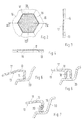
- the design of the screen filter 10 shown in Fig. 1 is typical for a dishwashing machine.
- the opening 11 embedded in the screen filter 10 normally surrounds a coarse filter that is set in the drainage shaft, wherein the edge 12, which sticks up on the underside 13 of the screen filter 10 accepts the fit after sealing.
- the edge 14 that encompasses the circumference of the screen filter 10 also protrudes on the underside 13 and serves the same purpose, as will be shown below.
- the screen filter 10 which is designed and manufactured as a plastic-injection mould part is relatively thin with a material thickness of approx. 1 to 1.2 mm and can therefore be produced with low material cost.
- reinforcement links 15 that stick up are injected on the underside 13 next to the edges 12 and 14 that have a thickness of between 0.5 mm and 0.8 mm and a height of approx. 2 mm and separate the fields 16.
- These fields 16 are designed for optimal use of space as standard hexagons that border each other in a honeycomb shape and cover the vast majority of the surface space of the screen filter 10.
- These fields 16 are provided with rows of flow holes 17, the arrangement of which will be shown as an example.
- the holes are arranged as shown in Fig. 8 .
- Flow passage is optimized in that the flow holes are arranged in the shape of an isosceles triangle.
- the distance “d1” equals the length of the sides.
- the distances “d1” and “d2” are contingent upon the minimal wall thicknesses.
- the screen is designed with two distances “d1” and “d2”; “d1” defines the hole spacing within a honeycomb and "d2" the minimum hole spacing between the outer holes of two bordering honeycombs (see Fig. 8 ).
- Figure 2 shows such a surface 16 of the screen filter 10 in the view of its underside 13.
- Reinforcement links 15 encompass the surface 16 and the adjacent surfaces 16 link up without surface loss.
- the flow holes 17 have a diameter of approx. 1 mm and are arranged in rows, wherein they provide a distance of approx. 2 mm in the rows.
- thirteen rows are provided that begin and end with seven flow holes on the edges of the field 6 and increase to thirteen flow holes 17 in the middle, as shown in the sectional views of Fig. 3 and 4 .
- the flow holes 17 may continually increase in profile from the topside to the underside 13 of the screen filter 10 in order to improve the flow of liquid that has been freed of solid particles.
- a truncated cone-like design of the flow holes 17 has proven to be particularly beneficial.
- the edge 14 of the screen filter 10 is designed, in a first embodiment of the invention, as a sealing lip which forms the transition from the screen filter 10 to the base 20 of the water conducting space, in order to seal the drainage shaft, as shown in Fig. 5 .
- the edge is designed as a double sealing lip, as Fig. 6 illustrates.
- edge 14 also provides receptacles 19 that allow for the attachment or injection of a separate, elastic sealing element 30, as shown in Fig. 7 .
Abstract
Description
- The present invention relates to a household dishwashing machine having a screen filter with flow holes, separating the washing space from a drainage shaft and lying at the bottom of the washing space, sealing the perimeter.
- Such a dishwashing machine is disclosed in
US-A-5700329 . Such document discloses a relatively flat screen type filter for a dishwasher made of metallic material, provided with legs to link the filter with other portions of the dishwasher.GB-A-1530206 - Filter screens of this type are usually designed as flexible metal punch-hole components that on the one hand can not optimally be designed in terms of flow restriction, i.e. the entire flow surface, and on the other hand cannot effectively seal the edges due to production reasons. The result is that often small solid particles cannot sufficiently be retained and end up in the drainage shaft.
- The task of the invention is to create a screen filter of the type mentioned at the outset that can be manufactured easily and cost efficiently and that is optimized in terms of flow restriction and the entire flow surface, provides an optimal sealing effect at the edges and that largely excludes the influence of material fatigue due to its design.
- This requirement is solved by the invention thanks to the features listed in the appended claims.
- The edge lining of the screen filter around the drainage shaft is improved and sealed in that a link web that protrudes vertically on the underside is designed as a sealing lip.
- The seal can be improved even more by providing the edge area with a double web that protrudes vertically on the underside that is designed as a double sealing lip or that is provided at the edge with an edging that protrudes out on the bottom side that is provided with receptacles for attaching an elastic sealing element.
- According to another preferred feature of the invention, the screen filter is equipped with flow holes that flare out in the flow direction, which are condensed to individual honeycombs in staggered row formation, that at the exterior of the edge it is provided with an orbiting, vertically aligned web that seals and is flat or linear shape, that it provides stiffening, injected reinforcement links in partitions on its underside, and the flow holes can be selected very small such that even the smallest of solid particles are retained. The number of flow holes can be selected very large to achieve a large overall flow area while simultaneously retaining very small solid particles. At the same time, reinforcement links on the bottom of the screen filter provide the screen filter with sufficient stability and stiffness even in thin screen filters. This also achieves long, device-specific lifetimes for screen filters manufactured in this way.
- The intended design of the screen filter is that it adopts a thickness of approx. 1 to 1.2 mm and that the diameter of the flow holes is approx. 1 mm and a distance of approx. 2 mm between adjacent rows. It is intended furthermore that adjacent rows of flow holes are each offset opposite to each other by half the distance between rows and the imaginary connection lines of the midpoint of three directly adjacent flow holes form an isosceles triangle, thus the entire flow surface can be optimized to the maximum by the honeycombs, which are separated by reinforcement links.
- The design of the reinforcement links provides for a thickness of between 0.5 to 0.8 mm and a height of approx. 2 mm.
- In one design, optimal use of screen filter surface space is achieved in that the reinforcement links arranged on the bottom separate individual, normally constructed, hexagonal honeycombs fields, which are furnished with "2 N -1" rows of flow holes, wherein "N" is the number of holes at the edges of the honeycombs. The design provides rows of holes at the honeycomb edge with "n" flow holes and rows of holes with "2 N -1" flow holes in the middle of the honeycombs field.
- Draining the liquid from which solid particles have been removed can be improved in that the profile of the flow holes flares out towards the underside, preferably designed as truncated cones.
- The invention is described in more detail using the example embodiments shown in the attached drawings in which:
- Fig. 1,
- is a perspective view of the underside of a screen filter for a dishwashing machine according to the invention,
- Fig. 2,
- is a partial view of the bottom side of a hexagonal field of the screen filter of
Figure 1 , - Fig. 3,
- is a sectional view along the line III-III of the field of
Figure 2 , - Fig. 4,
- is a sectional view along the line IV-IV of the field of
Figure 2 , - Fig. 5 to Fig. 7
- show three designs for the vertically aligned edge links of
Fig. 1 , and - Fig. 8
- shows the arrangement and design of the honeycomb-shape designed flow holes.
- The design of the
screen filter 10 shown inFig. 1 is typical for a dishwashing machine. Theopening 11 embedded in thescreen filter 10 normally surrounds a coarse filter that is set in the drainage shaft, wherein theedge 12, which sticks up on theunderside 13 of thescreen filter 10 accepts the fit after sealing. Theedge 14 that encompasses the circumference of thescreen filter 10 also protrudes on theunderside 13 and serves the same purpose, as will be shown below. - The
screen filter 10, which is designed and manufactured as a plastic-injection mould part is relatively thin with a material thickness of approx. 1 to 1.2 mm and can therefore be produced with low material cost. In order for the entire surface of thescreen filter 10 to maintain sufficient stability,reinforcement links 15 that stick up are injected on theunderside 13 next to theedges fields 16. Thesefields 16 are designed for optimal use of space as standard hexagons that border each other in a honeycomb shape and cover the vast majority of the surface space of thescreen filter 10. Thesefields 16 are provided with rows offlow holes 17, the arrangement of which will be shown as an example. - In order to attain the greatest flow passage within a honeycomb, the holes are arranged as shown in
Fig. 8 . Flow passage is optimized in that the flow holes are arranged in the shape of an isosceles triangle. The distance "d1" equals the length of the sides. The distances "d1" and "d2" are contingent upon the minimal wall thicknesses. In order to achieve maximum flow passage the screen is designed with two distances "d1" and "d2"; "d1" defines the hole spacing within a honeycomb and "d2" the minimum hole spacing between the outer holes of two bordering honeycombs (seeFig. 8 ). -
Figure 2 shows such asurface 16 of thescreen filter 10 in the view of itsunderside 13.Reinforcement links 15 encompass thesurface 16 and theadjacent surfaces 16 link up without surface loss. Theflow holes 17 have a diameter of approx. 1 mm and are arranged in rows, wherein they provide a distance of approx. 2 mm in the rows. In the example embodiment thirteen rows are provided that begin and end with seven flow holes on the edges of the field 6 and increase to thirteenflow holes 17 in the middle, as shown in the sectional views ofFig. 3 and 4 . Since the adjacent rows offlow holes 17 are always offset to each other by half the distance, the distance of the rows is kept small and the surface of thefield 16 can be used optimally for a large flow surface, however keep the surface offlow holes 17 very small in order to retain small solid particles as well. - The
flow holes 17 may continually increase in profile from the topside to theunderside 13 of thescreen filter 10 in order to improve the flow of liquid that has been freed of solid particles. A truncated cone-like design of theflow holes 17 has proven to be particularly beneficial. - The
edge 14 of thescreen filter 10 is designed, in a first embodiment of the invention, as a sealing lip which forms the transition from thescreen filter 10 to thebase 20 of the water conducting space, in order to seal the drainage shaft, as shown inFig. 5 . According to a second embodiment of the invention, the edge is designed as a double sealing lip, asFig. 6 illustrates. - Finally, the
edge 14 also providesreceptacles 19 that allow for the attachment or injection of a separate,elastic sealing element 30, as shown inFig. 7 .
Claims (9)
- A household dishwashing machine having a screen filter (10) with flow holes (17), which separates the washing space from a drainage shaft and lies at the bottom of the washing space, sealing the perimeter,
characterized in that
the screen filter (10) is designed and manufactured as a plastic-injection
mould part and it is provided with an the edge (14, 18) that protrudes vertically on the underside (13) as a sealing lip. - A household dishwashing machine according to claim 1, characterized in that the edge presents a double web (18) protruding vertically on the underside (13) as a double seal lip.
- A household dishwashing machine according to claim 1 or 2,
characterized in that the edge (14, 18) that protrudes vertically on the underside (13) is provided with receptacles (19) for mounting an elastic sealing element (30). - A household dishwashing machine according to any of the preceding claims,
characterized in that the screen filter (10) is provided with defined bearing surfaces that guarantee a favorable flow contact with retainers and also provide a positive form fit at the edge even after material fatigue has set in. - A household dishwashing machine according to any of the preceding claims,
characterized in that the screen filter (10) on its underside (13) is divided at least in partitions by means of injected reinforcement links (15) in fields (16) with flow holes (17) that are arranged in rows. - A household dishwashing machine according to any of the preceding claims,
characterized in that the reinforcement links (15) are designed as regular hexagons separating the fields (16) with rows of flow holes (17). - A household dishwashing machine according to any of the preceding claims,
characterized in that the rows of the flow holes (17) of the screen filter (10), which are at the edges of the field (16), are provided with N flow holes and in the middle of the field (16) with 2N-1 flow holes (17). - A household dishwashing machine according to any of the preceding claims,
characterized in that the reinforcement links (15) of the screen filter (10) have a thickness between 0.5 to 0.8 mm and a height of approx. 2 mm. - A household dishwashing machine according to any of the preceding claims,
characterized in that the profiles of the flow holes (17) grow continually larger in the direction of the underside (13), preferably designed truncated cone-shaped.
Applications Claiming Priority (2)
| Application Number | Priority Date | Filing Date | Title |
|---|---|---|---|
| DE2002108992 DE10208992B4 (en) | 2002-02-28 | 2002-02-28 | Filter screen for a liquid-conducting household appliance, in particular a dishwasher |
| EP03000076.4A EP1340448B2 (en) | 2002-02-28 | 2003-01-08 | A screen filter for a liquid-conducting device, in particular a dishwashing machine |
Related Parent Applications (2)
| Application Number | Title | Priority Date | Filing Date |
|---|---|---|---|
| EP03000076.4A Division-Into EP1340448B2 (en) | 2002-02-28 | 2003-01-08 | A screen filter for a liquid-conducting device, in particular a dishwashing machine |
| EP03000076.4A Division EP1340448B2 (en) | 2002-02-28 | 2003-01-08 | A screen filter for a liquid-conducting device, in particular a dishwashing machine |
Publications (3)
| Publication Number | Publication Date |
|---|---|
| EP2074921A2 true EP2074921A2 (en) | 2009-07-01 |
| EP2074921A3 EP2074921A3 (en) | 2009-08-12 |
| EP2074921B1 EP2074921B1 (en) | 2016-08-31 |
Family
ID=27675152
Family Applications (2)
| Application Number | Title | Priority Date | Filing Date |
|---|---|---|---|
| EP09154971.7A Expired - Lifetime EP2074921B1 (en) | 2002-02-28 | 2003-01-08 | A screen filter for a liquid-conducting device, in particular a dishwashing machine |
| EP03000076.4A Expired - Lifetime EP1340448B2 (en) | 2002-02-28 | 2003-01-08 | A screen filter for a liquid-conducting device, in particular a dishwashing machine |
Family Applications After (1)
| Application Number | Title | Priority Date | Filing Date |
|---|---|---|---|
| EP03000076.4A Expired - Lifetime EP1340448B2 (en) | 2002-02-28 | 2003-01-08 | A screen filter for a liquid-conducting device, in particular a dishwashing machine |
Country Status (3)
| Country | Link |
|---|---|
| EP (2) | EP2074921B1 (en) |
| DE (2) | DE10208992B4 (en) |
| ES (2) | ES2346518T3 (en) |
Cited By (2)
| Publication number | Priority date | Publication date | Assignee | Title |
|---|---|---|---|---|
| US9451864B2 (en) | 2011-04-29 | 2016-09-27 | Electrolux Home Products Corporation N.V. | Filter |
| US20220211245A1 (en) * | 2019-04-30 | 2022-07-07 | Qingdao Haier Dishwasher Co., Ltd. | Filter structure of dishwasher, and dishwasher |
Families Citing this family (9)
| Publication number | Priority date | Publication date | Assignee | Title |
|---|---|---|---|---|
| DE10359615A1 (en) * | 2003-12-18 | 2005-07-28 | BSH Bosch und Siemens Hausgeräte GmbH | Dishwasher with filter system |
| EP1709898A1 (en) * | 2005-04-05 | 2006-10-11 | Electrolux Home Products Corporation N.V. | Filter for a dishwasher |
| DE102010038582B4 (en) | 2010-07-28 | 2017-03-16 | BSH Hausgeräte GmbH | dishwasher |
| DE102010038584A1 (en) | 2010-07-28 | 2012-02-02 | BSH Bosch und Siemens Hausgeräte GmbH | Water-conducting household appliance, in particular dishwasher |
| DE102010038585A1 (en) | 2010-07-28 | 2012-02-02 | BSH Bosch und Siemens Hausgeräte GmbH | Aquiferous household appliance i.e. dishwasher, has hydraulic system in which flushing liquid is circulatable, where liquid flows through filter unit that has filter element comprising filter apertures formed as hexagonal holes |
| DE102010041158B4 (en) * | 2010-09-21 | 2023-07-06 | BSH Hausgeräte GmbH | dishwasher |
| PL2499954T3 (en) * | 2011-03-17 | 2017-10-31 | Electrolux Home Products Corp Nv | Dishwasher with a bistable filter |
| DE102012214318B4 (en) * | 2012-08-10 | 2016-12-01 | BSH Hausgeräte GmbH | Dishwasher, in particular household dishwasher |
| WO2015127982A1 (en) * | 2014-02-28 | 2015-09-03 | Arcelik Anonim Sirketi | Fine filter with improved filtration performance for use in a dishwasher and dishwasher having the same |
Citations (2)
| Publication number | Priority date | Publication date | Assignee | Title |
|---|---|---|---|---|
| GB1530206A (en) | 1975-09-18 | 1978-10-25 | Euro Hausgeraete Gmbh | Dishwashing machine |
| US5700329A (en) | 1996-05-22 | 1997-12-23 | White Consolidated Industries, Inc. | Filter standpipe for dishwasher |
Family Cites Families (16)
| Publication number | Priority date | Publication date | Assignee | Title |
|---|---|---|---|---|
| US3334750A (en) * | 1963-05-31 | 1967-08-08 | Mullins Mfg Corp | Dishwasher strainer with alternate filtering positions |
| US3322285A (en) * | 1965-01-05 | 1967-05-30 | Whirlpool Co | Filter for washing apparatus |
| US3591095A (en) * | 1968-11-25 | 1971-07-06 | Albert Di Stefano | Combination garbage grinder and pump |
| DE2555153A1 (en) * | 1975-12-08 | 1977-06-23 | Licentia Gmbh | Dish washing machine with water run off in rinsing container - has plastic seive with elongated holes inclined towards seive roller |
| DE2832084A1 (en) * | 1978-07-21 | 1980-01-31 | Licentia Gmbh | Dishwasher machine with plastics filter - has two displaceable mesh sieves which set mesh size according to position |
| US4201345A (en) * | 1978-08-04 | 1980-05-06 | General Electric Company | Food cutter for dishwasher |
| IT1099936B (en) * | 1978-10-18 | 1985-09-28 | Venturini Pio | DISHWASHER MACHINE FOR BARS, RESTAURANTS AND COMMUNITIES |
| AU527001B2 (en) * | 1978-12-29 | 1983-02-10 | Hobart International Inc. | Warewasher bypass soil collector |
| FR2508304B1 (en) * | 1981-06-30 | 1986-02-07 | Esswein Sa | DISHWASHER WITH AUTOMATICALLY CLEANED RECYCLING FILTER |
| DE3339281C1 (en) * | 1983-10-28 | 1985-06-05 | Bosch-Siemens Hausgeräte GmbH, 7000 Stuttgart | Device in the drainage trough of a dishwasher |
| IT211726Z2 (en) * | 1987-04-08 | 1989-04-07 | Zanussi Elettrodomestici | DISHWASHER MACHINE WITH ATUPOULENT RECIRCULATION FILTER. |
| IT1245021B (en) * | 1991-01-31 | 1994-09-13 | Merloni Elettrodomestici Spa | IMPROVEMENTS WITH A REMOVABLE FILTER FOR DISHWASHER |
| DE29607001U1 (en) * | 1996-04-17 | 1996-07-11 | Adek Bauteile Gmbh | Sieve for dishwashers, especially dishwashers |
| FR2760624A1 (en) * | 1997-03-13 | 1998-09-18 | Christophe Baudin | Automatic dishwasher adapted to communal service |
| IT245315Y1 (en) * | 1998-06-10 | 2002-03-20 | Electrolux Zanussi Elettrodome | DISHWASHER WITH PERFECTED FILTERING MEDIA |
| DE19841354C2 (en) | 1998-09-10 | 2003-04-30 | Aeg Hausgeraete Gmbh | Filter screen for a liquid-carrying household appliance |
-
2002
- 2002-02-28 DE DE2002108992 patent/DE10208992B4/en not_active Expired - Fee Related
-
2003
- 2003-01-08 EP EP09154971.7A patent/EP2074921B1/en not_active Expired - Lifetime
- 2003-01-08 DE DE60332786T patent/DE60332786D1/en not_active Expired - Lifetime
- 2003-01-08 EP EP03000076.4A patent/EP1340448B2/en not_active Expired - Lifetime
- 2003-01-08 ES ES03000076T patent/ES2346518T3/en not_active Expired - Lifetime
- 2003-01-08 ES ES09154971.7T patent/ES2596078T3/en not_active Expired - Lifetime
Patent Citations (2)
| Publication number | Priority date | Publication date | Assignee | Title |
|---|---|---|---|---|
| GB1530206A (en) | 1975-09-18 | 1978-10-25 | Euro Hausgeraete Gmbh | Dishwashing machine |
| US5700329A (en) | 1996-05-22 | 1997-12-23 | White Consolidated Industries, Inc. | Filter standpipe for dishwasher |
Cited By (2)
| Publication number | Priority date | Publication date | Assignee | Title |
|---|---|---|---|---|
| US9451864B2 (en) | 2011-04-29 | 2016-09-27 | Electrolux Home Products Corporation N.V. | Filter |
| US20220211245A1 (en) * | 2019-04-30 | 2022-07-07 | Qingdao Haier Dishwasher Co., Ltd. | Filter structure of dishwasher, and dishwasher |
Also Published As
| Publication number | Publication date |
|---|---|
| EP1340448A2 (en) | 2003-09-03 |
| EP1340448B2 (en) | 2019-05-22 |
| EP2074921B1 (en) | 2016-08-31 |
| ES2596078T3 (en) | 2017-01-04 |
| DE10208992A1 (en) | 2003-09-18 |
| EP1340448A3 (en) | 2003-09-24 |
| ES2346518T3 (en) | 2010-10-18 |
| EP2074921A3 (en) | 2009-08-12 |
| DE60332786D1 (en) | 2010-07-15 |
| EP1340448B1 (en) | 2010-06-02 |
| DE10208992B4 (en) | 2007-06-28 |
Similar Documents
| Publication | Publication Date | Title |
|---|---|---|
| EP2074921A2 (en) | A screen filter for a liquid-conducting device, in particular a dishwashing machine | |
| US20080282466A1 (en) | Drain hole waste trap and plug assembly | |
| JP2017083112A (en) | Indirect drain joint and cover body | |
| JP5319900B2 (en) | Hair catcher | |
| CN210842918U (en) | Filter equipment and dish washer | |
| KR20110011153A (en) | Filtering device for drain of sink | |
| KR101265027B1 (en) | Filter for sink of kitchen | |
| CN212129786U (en) | Kitchen waterproof floor | |
| JP5134513B2 (en) | Strainer and drainage structure having the same | |
| KR200368183Y1 (en) | Packing of drainage for dishwater stand | |
| JP3057782U (en) | Kitchen sink dust box lid | |
| KR200386306Y1 (en) | A garbage collecting filter of a dish washer | |
| CN210383837U (en) | Cleaning machine | |
| KR200434935Y1 (en) | Filter for sink | |
| CN211243228U (en) | Dish washing machine | |
| CN218458072U (en) | Split type kitchen dish washer | |
| JP3083513U (en) | Drainer container | |
| KR200338620Y1 (en) | drain unit of sink | |
| JP5674364B2 (en) | Waste bin for sink | |
| KR200366497Y1 (en) | Structure of packing for drain outlet of sink | |
| KR200224009Y1 (en) | Convexed filtering mesh | |
| JP2010126983A (en) | Strainer, and drain part structure having the same | |
| EP2601879B1 (en) | Filter for dishwasher and dishwasher comprising said filter | |
| JPS5924950Y2 (en) | Structure of drain trap | |
| JPH07268924A (en) | Sink drain port structure for kitchen counter |
Legal Events
| Date | Code | Title | Description |
|---|---|---|---|
| PUAI | Public reference made under article 153(3) epc to a published international application that has entered the european phase |
Free format text: ORIGINAL CODE: 0009012 |
|
| AC | Divisional application: reference to earlier application |
Ref document number: 1340448 Country of ref document: EP Kind code of ref document: P |
|
| AK | Designated contracting states |
Kind code of ref document: A2 Designated state(s): DE ES FR GB IT SE |
|
| PUAL | Search report despatched |
Free format text: ORIGINAL CODE: 0009013 |
|
| AK | Designated contracting states |
Kind code of ref document: A3 Designated state(s): DE ES FR GB IT SE |
|
| 17P | Request for examination filed |
Effective date: 20100127 |
|
| 17Q | First examination report despatched |
Effective date: 20100223 |
|
| AKX | Designation fees paid |
Designated state(s): DE ES FR GB IT |
|
| GRAP | Despatch of communication of intention to grant a patent |
Free format text: ORIGINAL CODE: EPIDOSNIGR1 |
|
| INTG | Intention to grant announced |
Effective date: 20160531 |
|
| GRAS | Grant fee paid |
Free format text: ORIGINAL CODE: EPIDOSNIGR3 |
|
| GRAA | (expected) grant |
Free format text: ORIGINAL CODE: 0009210 |
|
| AC | Divisional application: reference to earlier application |
Ref document number: 1340448 Country of ref document: EP Kind code of ref document: P |
|
| AK | Designated contracting states |
Kind code of ref document: B1 Designated state(s): DE ES FR GB IT |
|
| REG | Reference to a national code |
Ref country code: GB Ref legal event code: FG4D |
|
| REG | Reference to a national code |
Ref country code: DE Ref legal event code: R096 Ref document number: 60349352 Country of ref document: DE |
|
| REG | Reference to a national code |
Ref country code: FR Ref legal event code: PLFP Year of fee payment: 15 |
|
| REG | Reference to a national code |
Ref country code: ES Ref legal event code: FG2A Ref document number: 2596078 Country of ref document: ES Kind code of ref document: T3 Effective date: 20170104 |
|
| REG | Reference to a national code |
Ref country code: DE Ref legal event code: R097 Ref document number: 60349352 Country of ref document: DE |
|
| PLBE | No opposition filed within time limit |
Free format text: ORIGINAL CODE: 0009261 |
|
| STAA | Information on the status of an ep patent application or granted ep patent |
Free format text: STATUS: NO OPPOSITION FILED WITHIN TIME LIMIT |
|
| 26N | No opposition filed |
Effective date: 20170601 |
|
| REG | Reference to a national code |
Ref country code: FR Ref legal event code: PLFP Year of fee payment: 16 |
|
| PGFP | Annual fee paid to national office [announced via postgrant information from national office to epo] |
Ref country code: ES Payment date: 20180430 Year of fee payment: 16 |
|
| REG | Reference to a national code |
Ref country code: ES Ref legal event code: FD2A Effective date: 20200309 |
|
| PG25 | Lapsed in a contracting state [announced via postgrant information from national office to epo] |
Ref country code: ES Free format text: LAPSE BECAUSE OF NON-PAYMENT OF DUE FEES Effective date: 20190109 |
|
| PGFP | Annual fee paid to national office [announced via postgrant information from national office to epo] |
Ref country code: FR Payment date: 20211217 Year of fee payment: 20 Ref country code: GB Payment date: 20211206 Year of fee payment: 20 |
|
| PGFP | Annual fee paid to national office [announced via postgrant information from national office to epo] |
Ref country code: DE Payment date: 20211130 Year of fee payment: 20 |
|
| PGFP | Annual fee paid to national office [announced via postgrant information from national office to epo] |
Ref country code: IT Payment date: 20211213 Year of fee payment: 20 |
|
| REG | Reference to a national code |
Ref country code: DE Ref legal event code: R071 Ref document number: 60349352 Country of ref document: DE |
|
| REG | Reference to a national code |
Ref country code: GB Ref legal event code: PE20 Expiry date: 20230107 |
|
| PG25 | Lapsed in a contracting state [announced via postgrant information from national office to epo] |
Ref country code: GB Free format text: LAPSE BECAUSE OF EXPIRATION OF PROTECTION Effective date: 20230107 |