EP2074712B1 - Netz-/volumen-übertragungs-vorabzuweisung von upstream-ressourcen in einem satelliten-kommunikationssystem - Google Patents
Netz-/volumen-übertragungs-vorabzuweisung von upstream-ressourcen in einem satelliten-kommunikationssystem Download PDFInfo
- Publication number
- EP2074712B1 EP2074712B1 EP07868342A EP07868342A EP2074712B1 EP 2074712 B1 EP2074712 B1 EP 2074712B1 EP 07868342 A EP07868342 A EP 07868342A EP 07868342 A EP07868342 A EP 07868342A EP 2074712 B1 EP2074712 B1 EP 2074712B1
- Authority
- EP
- European Patent Office
- Prior art keywords
- user terminal
- web
- preallocation
- gateway
- satellite
- Prior art date
- Legal status (The legal status is an assumption and is not a legal conclusion. Google has not performed a legal analysis and makes no representation as to the accuracy of the status listed.)
- Active
Links
- 238000011144 upstream manufacturing Methods 0.000 title claims abstract description 69
- 238000012546 transfer Methods 0.000 title claims abstract description 54
- 238000004891 communication Methods 0.000 title description 23
- 230000004044 response Effects 0.000 claims abstract description 6
- 238000000034 method Methods 0.000 claims description 41
- 238000010586 diagram Methods 0.000 description 25
- 230000010287 polarization Effects 0.000 description 22
- 239000007858 starting material Substances 0.000 description 18
- 230000005540 biological transmission Effects 0.000 description 13
- 230000006870 function Effects 0.000 description 12
- 230000008569 process Effects 0.000 description 12
- 238000012545 processing Methods 0.000 description 11
- 230000008859 change Effects 0.000 description 8
- 238000009448 modified atmosphere packaging Methods 0.000 description 8
- 230000001960 triggered effect Effects 0.000 description 8
- 230000007246 mechanism Effects 0.000 description 7
- 238000013461 design Methods 0.000 description 6
- 230000009471 action Effects 0.000 description 4
- 238000006243 chemical reaction Methods 0.000 description 4
- 239000012634 fragment Substances 0.000 description 4
- 238000001228 spectrum Methods 0.000 description 4
- 230000001419 dependent effect Effects 0.000 description 3
- 238000009826 distribution Methods 0.000 description 3
- 238000005516 engineering process Methods 0.000 description 3
- 230000010354 integration Effects 0.000 description 3
- 238000007726 management method Methods 0.000 description 3
- 238000012986 modification Methods 0.000 description 3
- 230000004048 modification Effects 0.000 description 3
- 230000003287 optical effect Effects 0.000 description 3
- 230000007704 transition Effects 0.000 description 3
- 230000006399 behavior Effects 0.000 description 2
- 229920006235 chlorinated polyethylene elastomer Polymers 0.000 description 2
- 238000000136 cloud-point extraction Methods 0.000 description 2
- 230000000694 effects Effects 0.000 description 2
- 239000004744 fabric Substances 0.000 description 2
- 230000037361 pathway Effects 0.000 description 2
- 238000000926 separation method Methods 0.000 description 2
- 108700026140 MAC combination Proteins 0.000 description 1
- 230000003044 adaptive effect Effects 0.000 description 1
- 230000003321 amplification Effects 0.000 description 1
- 230000003466 anti-cipated effect Effects 0.000 description 1
- 238000013459 approach Methods 0.000 description 1
- 238000003491 array Methods 0.000 description 1
- 238000010276 construction Methods 0.000 description 1
- 230000008878 coupling Effects 0.000 description 1
- 238000010168 coupling process Methods 0.000 description 1
- 238000005859 coupling reaction Methods 0.000 description 1
- 230000003247 decreasing effect Effects 0.000 description 1
- 230000006735 deficit Effects 0.000 description 1
- 230000000593 degrading effect Effects 0.000 description 1
- 238000001914 filtration Methods 0.000 description 1
- 239000000796 flavoring agent Substances 0.000 description 1
- 235000019634 flavors Nutrition 0.000 description 1
- 230000004907 flux Effects 0.000 description 1
- 238000013467 fragmentation Methods 0.000 description 1
- 238000006062 fragmentation reaction Methods 0.000 description 1
- 239000000446 fuel Substances 0.000 description 1
- 230000001771 impaired effect Effects 0.000 description 1
- 238000003780 insertion Methods 0.000 description 1
- 230000037431 insertion Effects 0.000 description 1
- 238000002955 isolation Methods 0.000 description 1
- 235000019837 monoammonium phosphate Nutrition 0.000 description 1
- 239000003758 nuclear fuel Substances 0.000 description 1
- 238000003199 nucleic acid amplification method Methods 0.000 description 1
- 238000007781 pre-processing Methods 0.000 description 1
- 238000013442 quality metrics Methods 0.000 description 1
- 230000004043 responsiveness Effects 0.000 description 1
- 238000004513 sizing Methods 0.000 description 1
- 230000003068 static effect Effects 0.000 description 1
- 239000000126 substance Substances 0.000 description 1
- 238000012360 testing method Methods 0.000 description 1
- 239000002699 waste material Substances 0.000 description 1
Images


Classifications
-
- H—ELECTRICITY
- H04—ELECTRIC COMMUNICATION TECHNIQUE
- H04B—TRANSMISSION
- H04B7/00—Radio transmission systems, i.e. using radiation field
- H04B7/14—Relay systems
- H04B7/15—Active relay systems
- H04B7/204—Multiple access
- H04B7/212—Time-division multiple access [TDMA]
- H04B7/2121—Channels assignment to the different stations
- H04B7/2123—Variable assignment, e.g. demand assignment
-
- H—ELECTRICITY
- H04—ELECTRIC COMMUNICATION TECHNIQUE
- H04B—TRANSMISSION
- H04B7/00—Radio transmission systems, i.e. using radiation field
- H04B7/14—Relay systems
- H04B7/15—Active relay systems
- H04B7/185—Space-based or airborne stations; Stations for satellite systems
- H04B7/18578—Satellite systems for providing broadband data service to individual earth stations
- H04B7/18586—Arrangements for data transporting, e.g. for an end to end data transport or check
Definitions
- the present invention relates to wireless communications in general and, in particular, to a satellite communications network.
- a DAMA user SM is operative to transmit a request to the DAMA scheduler at the gateway, or SMTS, requesting upstream bandwidth sufficient to transmit the packet that is in its output queue.
- the arriving packet must wait a handshake interval until bandwidth is assigned.
- the handshake interval is the round trip time between the terminal and the central controller (in our case the SMTS), denoted RTT.
- the terminal will then transmit the packet and, ignoring the transmit time, the packet will arrive at the central controller one half an RTT later. This process implies that all packets arriving to an empty output queue will experience a delay of 1.5xRTT, not counting the contention delay. This delay of 1.5 x RTT is an irreducible lower bound.
- DOCSIS Best Effort DAMA is pure DAMA with the sole exception that requests for bandwidth can be piggybacked on transmitted data packets so as to take some of the loading off the contention channel, and hence increase overall system capacity. This means that a burst of packets arriving to a DOCSIS cable modem (CM) will have only one contention delay for the entire burst.
- CM DOCSIS cable modem
- the piggybacked request mechanism limits the request to just describe the packet in position 1 in the output queue (the packet being transmitted occupies position 0 in the output queue).
- a Demand Assigned Multiple Access (DAMA) scheduler is useful for relieving some of the load in a channel subject to contention.
- the goal of a DAMA scheduler in this instance is to reduce the number of assigned-but-unused minislots on the upstream channel (i.e. improve scheduling efficiency) without degrading webpage-download or FTP upload performance which uses the downstream channels.
- the ultimate goal is to provide more available upstream bandwidth to support more subscribers per upstream.
- burst transmission of packets a burst of packets can have only one contention delay for the entire burst.
- DAMA produces collisions in the contention channel since the arrival of packets is not deterministic, thus producing undesired latency and inefficiency in channel usage.
- DAMA is a potential tool in a mechanism to this end.
- CONNORS D P ET AL "RESPONSE INITIATED MULTIPLE ACCESS (RIMA), A MEDUM ACCESS CONTROL PROTOCOL FOR SATELLITE CHANNELS" GLOBECOM'00. 2000 IEEE GLOBAL TELECOMMUNICATIONS CONFERENCE.
- US-B1-6 778 509 discloses an approach for minimizing response times in transporting traffic over a packet radio communication system such as a satellite communication system.
- a terminal transmits a packet resource request message that specifies user terminal information using a contention channel according to a prescribed protocol.
- a gateway station receives the packet resource request message and transmits an assignment message that specifies a channel assignment based upon the user terminal information.
- US 2003/050008 A1 is directed to a scalable satellite data communication system that provides incremental global broadband services using Earth-fixed cells.
- the system has the flexibility to incrementally increase the number of Earth-fixed cells that are served, by adding satellites of potentially greater complexity to the system. Satellites may use mechanically-steered antennas. Communication links may be handed from one satellite to another when one satellite moves out of range and is no longer able to cover a selected Earth-fixed cell.
- the invention provides a method as defined in claim 1 or any of the dependent method claims 2 to 7. Further, the invention provides a system as defined in claim 8 or any of the dependent system claims 9 to 14.
- preallocation of upstream channel resources is provided by a scheduler at the gateway satellite modem termination system (SMTS) in response from the user terminal, wherein the user terminal detects web browser and/or bulk transfers involving large amounts of data transfer from users via the upstream channel.
- SMTS gateway satellite modem termination system
- a type length value (TLV) field is included with data packets transmitted to the gateway SMTS, at which excess transfer capability is allocated to the user terminal in anticipation of load requirements.
- FIGS. IA and IB are block diagrams of a satellite communication system
- Figures 2A and 2B are maps showing geographical distributions of beams.
- FIG. 3 is a block diagram of a gateway system.
- Figure 4 is a block diagram of a control system.
- Figure 5 is a block diagram of communication and control elements of a satellite relay.
- Figures 6A and 6B are block diagrams of upstream and downstream translators of Figure 5 .
- Figure 7 is a block diagram of a subscriber facility with a subscriber terminal.
- Figure 8 is a timing diagram of a forward channel superframe.
- Figure 9 is a timing diagram of a typical return channel superframe.
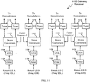
- FIG. 10 is a block diagram of a gateway transmitter.
- FIG 11 is a block diagram of a gateway receiver.
- Figures 12A and 12B are diagrams illustrating frequency allocation of a gateway.
- Figure 13 is a block diagram of a forward channel and return channels in a relay satellite.
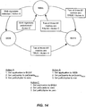
- Figure 14 is a diagram of a state machine according to the invention.
- FIG. 15 is a diagram of a state machine with detailed explanations according to the invention.
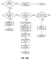
- Figures 16A-C left to right together are a flow chart according to the invention.
- Various embodiments of the present invention comprise systems, methods, devices, and software for a novel broadband satellite network.
- This description provides exemplary embodiments only, and is not intended to limit the scope, applicability or configuration of the invention. Rather, the ensuing description of the embodiments will provide those skilled in the art with an enabling description for implementing embodiments of the invention. Various changes may be made in the function and arrangement of elements without departing from the spirit and scope of the invention.
- various embodiments may omit, substitute, or add various procedures or components as appropriate.
- the methods may be performed in an order different than that described; and that various steps may be added, omitted or combined.
- features described with respect to certain embodiments may be combined in various other embodiments. Different aspects and elements of the embodiments may be combined in a similar manner. Also, a number of steps may be required before, after, or concurrently with the following embodiments.
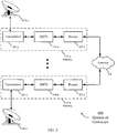
- FIG. 1A is a block diagram of an exemplary satellite communications system 100 configured according to various embodiments of the invention.
- the satellite communications system 100 includes a network 120, such as the Internet, interfaced with a gateway 115 that is configured to communicate with one or more subscriber terminals 130, via a satellite 105.
- a gateway 115 is sometimes referred to as a hub or ground station.
- Subscriber terminals 130 are sometimes called modems, satellite modems or user terminals.
- the communications system 100 is illustrated as a geostationary satellite 105 based communication system, it should be noted that various embodiments described herein are not limited to use in geostationary satellite based systems, for example some embodiments could be low earth orbit (LEO) satellite based systems.
- LEO low earth orbit
- the network 120 may be any type of network and can include, for example, the Internet, an IP network, an intranet, a wide-area network ("WAN"), a local-area network ("LAN”), a virtual private network, the Public Switched Telephone Network (“PSTN”), and/or any other type of network supporting data communication between devices described herein, in different embodiments.
- a network 120 may include both wired and wireless connections, including optical links. Many other examples are possible and apparent to those skilled in the art in light of this disclosure.
- the network may connect the gateway 115 with other gateways (not pictured), which are also in communication with the satellite 105.
- the gateway 115 provides an interface between the network 120 and the satellite 105.
- the gateway 115 may be configured to receive data and information directed to one or more subscriber terminals 130, and can format the data and information for delivery to the respective destination device via the satellite 105.
- the gateway 115 may be configured to receive signals from the satellite 105 (e.g., from one or more subscriber terminals) directed to a destination in the network 120, and can format the received signals for transmission along the network 120.
- a device (not shown) connected to the network 120 may communicate with one or more subscriber terminals, and through the gateway 115.
- Data and information may be sent from a device in the network 120 to the gateway 115.
- the gateway 115 may format a Medium Access Control (MAC) frame in accordance with a physical layer definition for transmission to the satellite 130.
- MAC Medium Access Control
- a variety of physical layer transmission modulation and coding techniques may be used with certain embodiments of the invention, including those defined with the DVB-S2 and WiMAX standards.
- the link 135 from the gateway 115 to the satellite 105 may be referred to hereinafter as the downstream uplink 135.
- the gateway 115 may use an antenna 110 to transmit the signal to the satellite 105.
- the antenna 110 comprises a parabolic reflector with high directivity in the direction of the satellite and low directivity in other directions.
- the antenna 110 may comprise a variety of alternative configurations and include operating features such as high isolation between orthogonal polarizations, high efficiency in the operational frequency bands, and low noise.
- a geostationary satellite 105 is configured to receive the signals from the location of antenna 110 and within the frequency band and specific polarization transmitted.
- the satellite 105 may, for example, use a reflector antenna, lens antenna, array antenna, active antenna, or other mechanism known in the art for reception of such signals.
- the satellite 105 may process the signals received from the gateway 115 and forward the signal from the gateway 115 containing the MAC frame to one or more subscriber terminals 130.
- the satellite 105 operates in a multi-beam mode, transmitting a number of narrow beams each directed at a different region of the earth, allowing for frequency re-use.
- the satellite 105 may be configured as a "bent pipe" satellite, wherein the satellite may frequency convert the received carrier signals before retransmitting these signals to their destination, but otherwise perform little or no other processing on the contents of the signals.
- a variety of physical layer transmission modulation and coding techniques may be used by the satellite 105 in accordance with certain embodiments of the invention, including those defined with the DVB-S2 and WiMAX standards. For other embodiments a number of configurations are possible (e.g., using LEO satellites, or using a mesh network instead of a star network), as evident to those skilled in the art.
- the service signals transmitted from the satellite 105 may be received by one or more subscriber terminals 130, via the respective subscriber antenna 125.
- the antenna 125 and terminal 130 together comprise a very small aperture terminal (VSAT), with the antenna 125 measuring approximately 0.6 meters in diameter and having approximately 2 watts of power.
- VSAT very small aperture terminal
- a variety of other types of antennas 125 may be used at the subscriber terminal 130 to receive the signal from the satellite 105.
- the link 150 from the satellite 105 to the subscriber terminals 130 may be referred to hereinafter as the downstream downlink 150.
- Each of the subscriber terminals 130 may comprise a single user terminal or, alternatively, comprise a hub or router (not pictured) that is coupled to multiple user terminals.
- Each subscriber terminal 130 may be connected to consumer premises equipment (CPE) 160 comprising, for example computers, local area networks, Internet appliances, wireless networks, etc.
- CPE consumer premises equipment
- a Multi-Frequency Time-Division Multiple Access (MF-TDMA) scheme is used for upstream links 140, 145, allowing efficient streaming of traffic while maintaining flexibility in allocating capacity among each of the subscriber terminals 130.
- MF-TDMA Multi-Frequency Time-Division Multiple Access
- a number of frequency channels are allocated which may be fixed, or which may be allocated in a more dynamic fashion.
- a Time Division Multiple Access (TDMA) scheme is also employed in each frequency channel. In this scheme, each frequency channel may be divided into several timeslots that can be assigned to a connection (i.e., a subscriber terminal 130).
- one or more of the upstream links 140, 145 may be configured with other schemes, such as Frequency Division Multiple Access (FDMA), Orthogonal Frequency Division Multiple Access (OFDMA), Code Division Multiple Access (CDMA), or any number of hybrid or other schemes known in the art.
- FDMA Frequency Division Multiple Access
- OFDMA Orthogonal Frequency Division Multiple Access
- CDMA Code Division Multiple Access
- a subscriber terminal may transmit data and information to a network 120 destination via the satellite 105.
- the subscriber terminal 130 transmits the signals via the upstream uplink 145-a to the satellite 105 using the antenna 125-a.
- a subscriber terminal 130 may transmit the signals according to a variety of physical layer transmission modulation and coding techniques, including those defined with the DVB-S2 and WiMAX standards.
- the physical layer techniques may be the same for each of the links 135, 140, 145, 150, or may be different.
- the link from the satellite 105 to the gateway 115 may be referred to hereinafter as the upstream downlink 140.
- FIG. 1B a block diagram is shown illustrating an alternative embodiment of a satellite communication system 100.
- This communication system 100 may, for example, comprise the system 100 of FIG. 1A , but is in this instance described with greater particularity.
- the gateway 1 15 includes a Satellite Modem Termination System (SMTS), which is based at least in part on the Data-Over-Cable Service Interface Standard (DOCSIS).
- DOCSIS Data-Over-Cable Service Interface Standard
- the SMTS in this embodiment includes a bank of modulators and demodulators for transmitting signals to and receiving signals from subscriber terminals 130.
- the SMTS in the gateway 115 performs the real-time scheduling of the signal traffic through the satellite 105, and provides the interfaces for the connection to the network 120.
- the subscriber terminals 135 use portions of DOCSIS-based modem circuitry, as well. Therefore, DOCSIS-based resource management, protocols, and schedulers may be used by the SMTS for efficient provisioning of messages.
- DOCSIS-based components may be modified, in various embodiments, to be adapted for use therein. Thus, certain embodiments may utilize certain parts of the DOCSIS specifications, while customizing others.
- a satellite communications system 100 applicable to various embodiments of the invention is broadly set forth above, a particular embodiment of such a system 100 will now be described.
- approximately 2 Gigahertz (GHz) of bandwidth is to be used, comprising four 500 Megahertz (MHz) bands of contiguous spectrum.
- Employment of dual-circular polarization results in usable frequency comprising eight 500 MHz non-overlapping bands with 4 GHz of total usable bandwidth.
- This particular embodiment employs a multi-beam satellite 105 with physical separation between the gateways 115 and subscriber spot beams, and configured to permit reuse of the frequency on the various links 135, 140, 145, 150.
- a single Traveling Wave Tube Amplifier (TWTA) is used for each service link spot beam on the downstream downlink, and each TWTA is operated at full saturation for maximum efficiency.
- a single wideband carrier signal for example using one of the 500 MHz bands of frequency in its entirety, fills the entire bandwidth of the TWTA, thus allowing a minimum number of space hardware elements.
- Spotbeam size and TWTA power may be optimized to achieve maximum flux density on the earth's surface of -118 decibel-watts per meter squared per Megahertz (dbW/m 2 /MHz). Thus, using approximately 2 bits per second per hertz (bits/s/Hz), there is approximately 1 Gbps of available bandwidth per spot beam.
- FIG. 12A an embodiment of a forward link distribution system 1200 is shown.
- the gateway 115 is shown coupled to an antenna 110, which generates four downstream signals.
- a single carrier with 500 MHz of spectrum is used for each of the four downstream uplinks 135.
- a total of two-frequencies and two polarizations allow four separate downstream uplinks 135 while using only 1 GHz of the spectrum.
- link A 135-A could be Freq 1U (27.5-28.0 GHz) with left-hand polarization
- link B 135-B could be Freq 1 U (27.5-28.0) GHz with right-hand polarization
- link C could be Freq 2U (29.5-30 GHz) with left-hand polarization
- link D could be Freq 2U (29.5-30 GHz) with left-hand polarization.
- the satellite 105 is functionally depicted as four "bent pipe” connections between a feeder and service link. Carrier signals can be changed through the satellite 105 "bent pipe” connections along with the orientation of polarization. The satellite 105 converts each downstream uplink 135 signal into a downstream downlink signal 150.
- downstream downlinks 150 there are four downstream downlinks 150 that each provides a service link for four spot beams 205.
- the downstream downlink 150 may change frequency in the bent pipe as is the case in this embodiment.
- downstream uplink A 135-A changes from a first frequency (i.e., Freq 1U) to a second frequency (i.e., Freq 1 D) through the satellite 105.
- Other embodiments may also change polarization between the uplink and downlink for a given downstream channel. Some embodiments may use the same polarization and/or frequency for both the uplink and downlink for a given downstream channel.
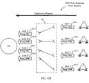
- FIG. 12B an embodiment of a return link distribution system is shown.
- This embodiment shows four upstream uplinks 145 from four sets of subscriber terminals 125.
- a "bent pipe" satellite 105 takes the upstream uplinks 145, optionally changes carrier frequency and/or polarization (not shown), and then redirects them as upstream downlinks 140 to a spot beam for a gateway 115.
- the carrier frequency changes between the uplink 145 and the downlink 140, but the polarization remains the same. Because the feeder spot beams to the gateway 115 is not in the coverage area of the service beams, the same frequency pairs may be reused for both service links and feeder links.
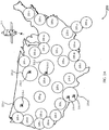
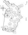
- FIGS . 2A and 2B examples of a multi-beam system 200 configured according to various embodiments of the invention are shown.
- the multi-beam system 200 may, for example, be implemented in the network 100 described in FIGS . 1A and 1B . Shown are the coverage of a number of feeder and service spot beam regions 225, 205.
- a satellite 215 reuses frequency bands by isolating antenna directivity to certain regions of a country (e.g., United States, Canada or Brazil).
- FIG. 2A there is complete geographic exclusivity between the feeder and service spot beams 205, 225. But that is not the case for FIG.
- service spot beam overlap e.g., 205-c, 205-d, 205-e
- a four color pattern allows avoiding interference even where there is some overlap between neighboring service beams 205.
- the gateway terminals 210 are also shown along with their feeder beams 225. As shown in FIG. 2B , the gateway terminals 210 may be located in a region covered by a service spotbeam (e.g., the first, second and fourth gateways 210-1, 210-2, 210-4). However, a gateway may also be located outside of a region covered by a service spotbeam (e.g., the third gateway 210-3). By locating gateway terminals 210 outside of the service spotbeam regions (e.g., the third gateway 210-3), geographic separation is achieved to allow for re-use of the allocated frequencies.
- a service spotbeam e.g., the first, second and fourth gateways 210-1, 210-2, 210-4
- a gateway may also be located outside of a region covered by a service spotbeam (e.g., the third gateway 210-3).
- the spare gateway terminal 210-5 can substitute for the primary gateway terminal 210-4 should the primary gateway terminal 210-4 fail to function properly. Additionally, the spare can be used when the primary is impaired by weather.
- the downstream channel 800 includes a series of superframes 804 in succession, where each superframe 804 may have the same size or may vary in size.
- This embodiment divides a superframe 804 into a number of virtual channels 808(1 -n).
- the virtual channels 808(1-n) in each superframe 804 can be the same size or different sizes.
- the size of the virtual channels 808(1-n) can change between different superframes 804. Different coding can be optionally used for the various virtual channels 808 (1-n).
- the virtual channels are as short as one symbol in duration.
- an embodiment of an upstream channel 900 is shown. This embodiment uses MF-TDMA, but other embodiments can use CDMA, OFDM, or other access schemes.
- the upstream channel 900 has 500 MHz of total bandwidth in one embodiment. The total bandwidth is divided into m frequency sub-channels , which may differ in bandwidth, modulation, coding, etc. and may also vary in time based on system needs.
- each subscriber terminal 130 is given a two-dimensional (2D) map to use for its upstream traffic.
- the 2D map has a number of entries where each indicates a frequency sub-channel 912 and time segment 908(1-5). For example, one subscriber terminal 130 is allocated sub-channel m 912-m, time segment one 908-1; sub-channel two 912-2, time segment two 908-2; sub-channel two 912-2, time segment three 908-3; etc.
- the 2D map is dynamically adjusted for each subscriber terminal 130 according to anticipated need by a scheduler in the SMTS.
- the forward channel 800 includes n virtual channels 808 traveling from the gateway antenna 110 to the service spot beam 205.
- Each subscriber terminal 130 may be allocated one or more of the virtual channels 808.
- m MF-TDMA channels 912 make up the return channel 900 between the subscriber terminal (ST) antennas 125 and the feeder spot beam 225.
- FIG. 3 an embodiment of a ground system 300 of gateways 115 is shown in block diagram form.
- One embodiment could have fifteen active gateways 115 (and possibly spares) to generate sixty service spot beams, for example.
- the ground system 300 includes a number of gateways 115 respectively coupled to antennas 110. All the gateways 115 are coupled to a network 120 such as the Internet. The network is used to gather information for the subscriber terminals. Additionally, each SMTS communicates with other SMTS and the Internet using the network 120 or other means not shown.
- Each gateway 115 includes a transceiver 305, a SMTS 310 and a router 325.
- the transceiver 305 includes both a transmitter and a receiver.
- the transmitter takes a baseband signal and upconverts and amplifies the baseband signal for transmission of the downstream uplinks 135 with the antenna 110.
- the receiver downconverts and tunes the upstream downlinks 140 along with other processing as explained below.
- the SMTS 310 processes signals to allow the subscriber terminals to request and receive information and schedules bandwidth for the forward and return channels 800, 900. Additionally, the SMTS 310 provides configuration information and receives status from the subscriber terminals 130. Any requested or returned information is forwarded via the router 325.
- gateway receiver 1100 processes four return channels 900 from four different service spot beams 205.
- the return channels 900 may be divided among four pathways using antenna polarization and/or filtering 1104.
- Each return channel is coupled to a low-noise amplifier (LNA) 1108.
- LNA low-noise amplifier
- Down conversion 1112 mixes down the signal into its intermediate frequency.
- Each of the upstream sub-channels 912 is separated from the signal by a number of tuners 1116. Further processing is performed in the SMTS 310.
- each downstream channel 800 is up-converted 1004 using two different carrier frequencies.
- a power amplifier 1008 increases the amplitude of the forward channel 900 before coupling to the antenna 110.
- the antenna 110 polarizes the separate signals to keep the four forward channels 800 distinct as they are passed to the satellite 105.
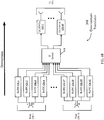
- a SMTS 310 is shown in block diagram form. Baseband processing is done for the inbound and outbound links 135, 140 by a number of geographically separated gateways 115. Each SMTS 310 is generally divided into two sections, specifically, the downstream portion 305 to send information to the satellite 105 and the upstream portion 315 to receive information from the satellite 105.
- the downstream portion 305 takes information from the switching fabric 416 through a number of downstream (DS) blades 412.
- the DS blades 412 are divided among a number of downstream generators 408.
- This embodiment includes four downstream generators 408, with one for each of the downstream channels 800. For example, this embodiment uses four separate 500 MHz spectrum ranges having different frequencies and/or polarizations.
- a four-color modulator 436 has a modulator for each respective DS generator 408.
- the modulated signals are coupled to the transmitter portion 1000 of the transceiver 305 at an intermediate frequency.
- Each of the four downstream generators 408 in this embodiment has J virtual DS blades 412.
- the upstream portion 315 of the SMTS 310 receives and processes information from the satellite 105 in the baseband intermediate frequency. After the receiver portion 1100 of the transceiver 305 produces all the sub-channels 912 for the four separate baseband upstream signals, each sub-channel 912 is coupled to a different demodulator 428. Some embodiments could include a switch before the demodulators 428 to allow any return link sub-channel 912 to go to any demodulator 428 to allow dynamic reassignment between the four return channels 908. A number of demodulators are dedicated to an upstream (US) blade 424.
- US upstream
- the US blades 424 serve to recover the information received from the satellite 105 before providing it to the switching fabric 416.
- the US scheduler 430 on each US blade 424 serves to schedule use of the return channel 900 for each subscriber terminal 130. Future needs for the subscriber terminals 130 of a particular return channel 900 can be assessed and bandwidth/latency adjusted accordingly in cooperation with the Resource Manager and Load Balancer (RM/LB) block 420.
- RM/LB Resource Manager and Load Balancer
- the RM/LB block 420 assigns traffic among the US and DS blades.
- each RM/LB block 420 can reassign subscriber terminals 130 and channels 800, 900 to other gateways 115. This reassignment can take place for any number of reasons, for example, lack of resources and/or loading concerns.
- the decisions are done in a distributed fashion among the RM/LB blocks 420, but other embodiments could have decisions made by one master MR/LB block or at some other central decision-making authority.
- Reassignment of subscriber terminals 130 could use overlapping service spot beams 205, for example.
- FIG. 5 an embodiment of a satellite 105 is shown in block diagram form.
- the satellite 105 in this embodiment communicates with fifteen gateways 115 and all STs 130 using sixty feeder and service spot beams 225, 205. Other embodiments could use more or less gateways/spot beams.
- Bus power 512 is supplied using a power source such as chemical fuel, nuclear fuel and/or solar energy.
- a satellite controller 516 is used to maintain attitude and otherwise control the satellite 105. Software updates to the satellite 105 can be uploaded from the gateway 115 and performed by the satellite controller 516.
- a downstream translator 508 receives information from the fifteen gateways 115 for relay to subscriber terminals 130 using sixty service spot beams 205.
- An upstream translator 504 receives information from the subscriber terminals 130 occupying the sixty spot beam areas and relays that information to the fifteen gateways 115.
- This embodiment of the satellite can switch carrier frequencies in the downstream or upstream processors 508, 504 in a "bent-pipe" configuration, but other embodiments could do baseband switching between the various forward and return channels 800, 900.
- the frequencies and polarization for each spot beam 225, 205 could be programmable or preconfigured.
- a Receiver and Downconverter (Rx/DC) block 616 receives all the return link information for the area defined by a spot beam 205 as an analog signal before conversion to an intermediate frequency (IF). There is a Rx/DC block 616 for each service spot beam area 205.
- An IF switch 612 routes a particular baseband signal from a Rx/DC block 616 to a particular upstream downlink channel.
- the upstream downlink channel is filled using an Upconverter and Traveling Wave Tube Amplifier (UC/TWTA) block 620.
- U/TWTA Upconverter and Traveling Wave Tube Amplifier
- Each gateway 115 has four dedicated UC/TWTA blocks 620 in the upstream translator 504. Two of the four dedicated UC/TWTA blocks 620 operate at a first frequency range and two operate at a second frequency range in this embodiment. Additionally, two use right-hand polarization and two use left-hand polarization. Between the two polarizations and two frequencies, the satellite 105 can communicate with each gateway 115 with four separate upstream downlink channels.
- Each gateway 115 has four downstream uplink channels to the satellite 105 by use of two frequency ranges and two polarizations.
- a Rx/DC block 636 takes the analog signal and converts the signal to an intermediate frequency. There is a Rx/DC block 636 for all sixty downstream uplink channels from the fifteen gateways 115.
- the IF switch 612 connects a particular channel 800 from a gateway 115 to a particular service spot beam 205. Each IF signal from the switch 628 is modulated and amplified with a UC/TWTA block 632.
- An antenna broadcasts the signal using a spot beam to subscriber terminals 130 that occupy the area of the spot beam.
- the downstream translator 508 can change carrier frequency and polarization of a particular downstream channel in a bent-pipe fashion.
- FIG. 7 comprises a block diagram illustrating a set of subscriber equipment 700 which may be located at a subscriber location for the reception and transmission of communication signals.
- Components of this set of subscriber equipment 700 may, for example, comprise the antenna 125, associated subscriber terminal 130 and any consumer premises equipment (CPE) 160, which may be a computer, a network, etc.
- CPE consumer premises equipment
- An antenna 125 may receive signals from a satellite 105.
- the antenna 125 may comprise a VSAT antenna, or any of a variety other antenna types (e.g., other parabolic antennas, microstrip antennas, or helical antennas).
- the antenna 125 may be configured to dynamically modify its configuration to better receive signals at certain frequency ranges or from certain locations. From the antenna 125, the signals are forwarded (perhaps after some form of processing) to the subscriber terminal 130.
- the subscriber terminal 130 may include a radio frequency (RF) front end 705, a controller 715, a virtual channel filter 702, a modulator 725, a demodulator 710, a filter 706, a downstream protocol converter 718, an upstream protocol converter 722, a receive (Rx) buffer 712, and a transmit (Tx) buffer 716.
- RF radio frequency
- the RF front end 705 has both transmit and receive functions.
- the receive function includes amplification of the received signals (e.g., with a low noise amplifier (LNA)).
- LNA low noise amplifier
- This amplified signal is then downconverted (e.g., using a mixer to combine it with a signal from a local oscillator (LO)).
- This downconverted signal may be amplified again with the RF front end 705, before processing of the superframe 804 with the virtual channel filter 702.
- a subset of each superframe 804 is culled from the downstream channel 800 by the virtual channel filter 702, for example, one or more virtual channels 808 are filtered off for further processing.
- modulation and coding techniques may be used at the subscriber terminal 130 for signals received from and transmitted to a satellite.
- modulation techniques include BPSK, QPSK, 8PSK, 16APSK, 32PSK.
- additional modulation techniques may include ASK, FSK, MFSK, and QAM, as well as a variety of analog techniques.
- the demodulator 710 may demodulate the downconverted signals, forwarding the demodulated virtual channel 808 to a filter 706 to strip out the data intended for the particular subscriber terminal 130 from other information in the virtual channel 808.
- a downstream protocol converter 718 translates the protocol used for the satellite link into one that the DOCSIS MAC block 726 uses.
- Alternative embodiments could use a WiMAX MAC block or a combination DOCSIS/WiMAX block.
- a Rx buffer 712 is used to convert the high-speed received burst into a lower-speed stream that the DOCSIS MAC block 726 can process.
- the DOCSIS MAC block 726 is a circuit that receives a DOCSIS stream and manages it for the CPE 160. Tasks such as provisioning, bandwidth management, access control, quality of service, etc. are managed by the DOCSIS MAC block 726.
- the CPE can often interface with the DOCSIS MAC block 726 using Ethernet, WiFi, USB and/or other standard interfaces.
- a WiMax block 726 could be used instead of a DOCSIS MAC block 726 to allow use of the WiMax protocol.
- downstream protocol converter 718 and upstream protocol converter 722 may be used to convert received packets to DOCSIS or WiMax compatible frames for processing by a MAC block 726, these converters will not be necessary in many embodiments.
- the protocol used for the satellite link may also be compatible with the MAC block 726 without such conversions, and the converters 718, 722 may therefore be excluded.
- the controller 715 may oversee a variety of decoding, interleaving, decryption, and unscrambling techniques, as known in the art.
- the controller may also manage the functions applicable to the signals and exchange of processed data with one or more CPEs 160.
- the CPE 160 may comprise one or more user terminals, such as personal computers, laptops, or any other computing devices as known in the art.
- the controller 715 may be implemented in one or more Application Specific Integrated Circuits (ASICs), or a general purpose processor adapted to perform the applicable functions.
- ASICs Application Specific Integrated Circuits
- the functions of the subscriber terminal 130 may be performed by one or more other processing units (or cores), on one or more integrated circuits.
- other types of integrated circuits may be used (e.g., Structured/Platform ASICs, Field Programmable Gate Arrays (FPGAs) and other Semi-Custom ICs), which may be programmed in any manner known in the art.
- the controller may be programmed to access memory unit (not shown). It may fetch instructions and other data from the memory unit, or write data to the memory-unit.
- data may also be transmitted from the CPE 160 through the subscriber terminal 130 and up to a satellite 105 in various communication signals.
- the CPE 160 may transmit data to DOCSIS MAC block 726 for conversion to the DOCSIS protocol before that protocol is translated with an upstream protocol converter 722.
- the slow-rate data waits in the Tx buffer 716 until it is burst over the satellite link.
- the processed data is then transmitted from the Tx buffer 716 to the modulator 725, where it is modulated using one of the techniques described above.
- adaptive or variable coding and modulation techniques may be used in these transmissions. Specifically, different modulation and coding combinations, or "modcodes,” may be used for different packets, depending on the signal quality metrics from the antenna 125 to the satellite 105. Other factors, such as network and satellite congestion issues, may be factored into the determination, as well. Signal quality information may be received from the satellite or other sources, and various decisions regarding modcode applicability may be made locally at the controller, or remotely.
- the RF frontend 705 may then amplify and upconvert the modulated signals for transmission through the antenna 125 to the satellite.
- pre-allocation Both web-triggered pre-allocation and bulk transfer are considered "pre-allocation".
- the SMTS scheduler is granting in a speculative manner based upon the arrival of a real request.
- the scheduler is pre-allocating in a measured manner, seeking to match the upstream grant rate with the upstream bulk transfer need.
- Web triggered pre-allocation uses a web signature to identify HTTP sessions and subsequently engages pre-allocation. Grants are always made in pairs (subject to grant minislot limitations). The first grant is based upon a real request and the second is a speculative grant based upon paQuanta.
- Upstream PHY configuration limits maximum upstream transmission size to be in the neighborhood of 4K bytes in a specific design. If a user is engaging in an FTP transfer in the upstream, with a 1500 byte packet size, this will cause XTP to send one concatenated frame of size 3000 bytes per round trip time (4.5K bytes would exceed the concatenation threshold).
- Our round trip times for MTD-DAMA typically are between 600 and 650 milliseconds. This results in a throughput of approximately 38 Kb/s.
- BToDAMA Bulk Transfer over DAMA
- Doc a signature
- P 2 Phantom Packet
- BToDAMA also introduces a greedy algorithm for increasing the upstream rate to match either the CoS rate or the lowest rate seen in the WAN.
- BToDAMA assumes the basic DAMA mechanisms are in play, those being piggybacking requests and granting bandwidth once per RTT.
- BToDAMA uses a unified proprietary TLV (pTLV) which seeks to communicate to the scheduler that Bulk Transfer (BT) has been identified and what additional grants are desired.
- pTLV unified proprietary TLV
- BT Bulk Transfer
- the pTLV does not supersede the hardware generated piggybacked request, nor is there a tight timing relationship between the pTLV and hardware generated piggybacked requests.
- the upstream rate needs to be set such that the terminals CoS rate can be realized while at the same time minimizing bandwidth waste. This involves increasing the upstream rate in a greedy, opportunistic manner until either the CoS rate is achieved, the scheduler has no more bandwidth to assign, or that any additional upstream bandwidth will go wasted due to a bottleneck further down the path.
- the proprietary TLV (pTLV) will take the following conceptual form.
- the application field identifies the application state. It takes the values NULL, WEB, and BULK. This field ought to be two bits in length. If a particular application is disabled or if no application has been identified, then the application field will be set to NULL.
- the paQuanta field identifies the pre-allocation grant size in units of the minimum grant size in bytes (ie, 138-bytes). This field ought to be six bits in length.
- the paMultiplier indicates the number of individual grants of size paQuanta mini-slots that the SMTS scheduler must contiguously assign (or as best as can be done, using grants pending). This field ought to be eight bits in length.
- the SMTS scheduler When a request is received, either via a request channel or via a piggybacked request, the SMTS scheduler should honor this request (standard DAMA behavior) and then provide another grant or grants, within the same MAP if possible. For either pre-allocation application, the action at the SMTS scheduler is the same. The SMTS scheduler must allocate paMultiplier grants of size paQuanta mini-slots. If the scheduler cannot allocate the entire number of grants, it must assert "Grants Pending" and assign the remainder in the next MAP interval(s).
- the SMTS will need to maintain state for each registered SM.
- the state that it needs to maintain is just what is contained in the pTLV, namely the identified application (NULL, BULK, or WEB), the current pre-allocation amount (paQuanta, measured in minislots), and the paMultiplier.
- the state table is updated. There should also be an expiry value. Each time a pTLV is received, this state table is updated and an expiry value is updated as well. If no pTLV is received for some time then the state table for this SM should be purged. This will help in garbage collection. The expiry should be on the order of half minutes.
- Updating the state table and generating pre-allocation grants are separate. There is no timing relationship between the two.
- the state table is updated whenever a pTLV is received.
- a speculative grant is given each time a real request arrives and the state table indicates that the SM is requesting pre-allocation. Because of this, there may be a very small lag between what ⁇ paQuanta, paMultiplier> value the scheduler is using and what this value is about to change to (i.e. updated value). So, for instance, if a concatenated packet arrives with a piggybacked request and an updated pTLV, the request will most likely be considered first and the pre-allocation grant made based upon the values in the state table without this latest pTL V update .
- the pTLV will be used to update the state table once the frame emerges from the Upstream Post Processor block, which will most likely be after the piggybacked request is processed. Attempting to make a tight timing relationship between requests and pTLV updates is very messy and perhaps not possible.
- the standard Best Effort algorithm in the SMTS has a "credit-borrowing" feature to compliment its Deficit Round-Robin (DRR) algorithm which allows a service flow to keep left-over credits from a previous grant for that flow. It aids in allowing grants to get serviced quicker and avoids excessive looping in the algorithm.
- DRR Deficit Round-Robin
- This feature is only applied to grants whose requests are made via a piggy-back request, thus signifying that there is backlog at the SM. Random-channel request grants start out with a credit value of zero.
- One such metric is the measure of the percentage of map mini-slots that are contention slots. This is done by defining a timed window (provisioned) over which to accumulate total map mini-slots throughout the window and total contention slots throughout the window. Also provisioned is a threshold value which represents the percentage of contention that constitutes congestion for the channel. At the expiration of each window, the percentage of contention space is computed by dividing the accumulated contention slots by the total map minislots for the window and stored. The accumulators are then cleared for the next window.
- pre-allocation is disabled for the duration of the request. If above the threshold, web pre-allocation is allowed. This algorithm does NOT apply to bulk transfer pre-allocation.
- the Application State Machine provides a means of knowing modem state with respect to the flavor of pre-allocation.
- the ASM transitions to the BULK state, regardless of the current state.
- the NULL state if either web activity is detected or bulk transfer, then the ASM transitions to the appropriate state.
- the SM will always signal using the ASM. In cases where the channel is congested, the SMTS will ignore WEB preallocation. The SMTS will always grant BULK preallocation requests, unless it is manually disabled.
- the ASM moves to WEB state and updates the pTLV paQuanta using the web quanta (The paMultiplier field will be set to one). If there are several seconds in which no new triggering events occur, the ASM drops out of WEB and moves to BULK or NULL, depending on the state of the BULK metrics.
- a 5 second timer is started (or restarted if already running). Until this timer runs out (i.e. it has been 5 seconds since the last web query), the SM will request web pre-allocation, regardless of bulk metrics. When the timer runs out, the SM will move into whatever state the current bulk metrics indicate (either BULK or NULL).
- a bulk transfer is detected using three metrics. When any two of this metrics meet certain criterion, the bulk transfer is declared, the ASM transitions to the BULK state, and the pTLV is populated according to the prescriptions of bulk transfer
- a windowed arrival rate is generated by measuring the arrival rate to the SWQ. This rate should be measured in b/s, averaged over a configurable window.
- the indicator I 1 is set to TRUE.
- this rate metric may not be a good indicator after the bulk transfer is in steady-state, but will trigger almost immediately when entering bulk.
- An average byte backlog in the HWQ is generated by recording the byte backlog in the HWQ upon dumping a (concatenated) frame from the SWQ to the HWQ.
- the byte backlog must be measured prior to the dump. This metric must be a sliding window and therefore the measured backlogs must be stored in a ring buffer.
- the ring buffer must be accumulated and then divided to get the average. For this reason it is advisable that the size of the ring buffer be a power of two, such that the division is simply a right shift.
- the size of the ring buffer, S RB-2 is a parameter of experimentation, however for starters it should be 8.
- This average byte backlog forms M 2 . When M 2 exceeds threshold two (T 2 ), the indicator for Metric 2, I 2, is set to TRUE.
- M 2 ⁇ i ring_buffer i > > log 2 ⁇ S RB - 2
- M 2 is a good metric at bulk transfer startup, however once steady state is reached, the backlog should become small and therefore this metric may become FALSE.
- a value for T 2 for initial integration and test is 1500 bytes.
- the ring buffer size (S RB-3 ) be a power of two, such that the division is simply a right shift.
- Metric 3 should be a good indicator of bulk transfer both at startup and at steady state and therefore will serve as an anchor for identifying bulk transfer throughout the process from startup to steady state.
- the Event Driven State Machine provides instruction for how the SM should act given that an event has occurred. There are four different events.
- the ESM is shown in FIG. 15 .
- This state machine supports Web triggered preallocation (PAv2), and BToDAMA, as well as other functions.
- PAv2 Web triggered preallocation
- BToDAMA BToDAMA
- cp2 The (concatenated) frame that sits at the head of the SWQ.
- the SM When a packet descriptor is reclaimed, the SM will take Actions A through C.
- ReclaimTxFrames() When the function ReclaimTxFrames() is executed, this represents either the conclusion of a transmitted frame or frame fragment.
- ReclaimTxFrames() When ReclaimTxFrames() is executed, the VQ is updated if a (concatenated) frame is known to have completed transmission. This design makes no assumptions about the nature of ReclaimTxFrames(). If it is called each time a fragment is transmitted, rather than the entire (concatenated) frame, the state machine of FIG. 15 will still function properly.
- VQ Virtual Queue
- a VQ entry will take the abstract form: ⁇ Frame Id>, ⁇ Bytes Remaining>, ⁇ Fragmented Flag>, ⁇ Done Flag>, ⁇ HWQ Empty Upon Dump Flag>, ⁇ Phantom Packet Flag>, and ⁇ Final Frame Flag>.
- an entry takes the following structure.:
- the VQEntry.bytesRemaining value is the total length (total_len) of the frame if un-concatenated or the concatenated length (concat_len) if the frame is a concatenated frame.
- VQEntry.list_of_framelds must be selected to represent the entire frame.
- the function ReclaimTxFrames() executes, packet descriptors and buffer descriptors are reclaimed for SW use.
- a (concatenated) frame is fully transmitted (i.e. no more fragments remain in the HWQ)
- the entry at the head of the VQ will be purged.
- the entry can be purged when all packets in the list_of_frameIds have been reclaimed.
- the fragmented flag is set to TRUE if the (concatenated) frame under goes fragmentation over the course of its transmission.
- the done flag represents the SW's understanding of progress in the hardware queue.
- the p2Flag field is set to TRUE in the VQ entry if the frame which is being dumped to the SWQ is in fact a Phantom Packet (P 2 ). For all other frames, this is set to FALSE.
- the finalFrameFlag field is set to TRUE in the VQ entry if the frame being dumped is being dumped due to a grant which is the last grant in a series of grants. Typically this flag is only set for Phantom Packets. This is described in more detail hereinafter below.
- the depth of the VQ is driven by the needs of bulk transfer. Assuming that our concatenation limit is ⁇ 4000 bytes and that the upstream rate is 512 Kb/s. This corresponds to a XTP transmit window of 62,400 bytes (650 milliseconds * 512 Kb/s * 1.5/8). If we take this value and divide by 4000, this makes for 16 concatenated frames, therefore the VQ must have at least 16 - 20 entries.
- MAPs arrive at the SM, both the hardware and software parse through them.
- the software When a MAP arrives, the software must perform pre-processing to make a tuple ⁇ grantSizelnBytes, lastGrantFlag>.
- a grant tuple has lastGrantFlag set to TRUE if it is the last grant allocated to a particular terminal in the MAP and there are no "Grants Pending" for this terminal. Otherwise it is set to FALSE.
- This flow chart supports MTD, PAv2, and BToDAMA.
- the Phantom Packet is dumped from the SWQ to the HWQ when an arriving series of grants will not only empty the HWQ but also empty the SWQ.
- the Phantom Packet (P 2 ) is a frame that will be discarded by the SMTS and will fit into a single turbo code word (33 - 35 bytes). Phantom Packets will be inserted for all otherwise unusable grants.
- Phantom Packets will be used in both PAv2 and BToDAMA to keep the DAMA channel active and out of the random channel. If a source goes silent, Phantom Packets will no longer be inserted.
- the Phantom Packet is an upstream MAC Management message with an ID of 252.
- the buffer occupancy of the HWQ must be inspected. If the HWQ is empty, then a counter that is SID specific (i.e. global across all frames within the SID) name HW.QEmptyCounter is incremented. If the HWQ is not empty, then this global variable remains unchanged. Every N D dump events, upon the conclusion of the dump, this global variable is inspected. If the HWQEmptyCounter is greater than or equal to a threshold (currently 2), increase the paMultiplier field of the pTLV by I M . Either way, the HWQEmptyCounter is reset to 0.
- a threshold currently 2
- the increment of the multiplier is meant to increase the upstream grant rate.
- each N D we want the scheduler to allocate enough grants to carry one additional concatenated frame per RTT.
- the increment I M is set based upon the average size of a MTD frame divided by the paQuanta value. To simplify the design, we set I M to be the concat threshold divided by the paQuanta value. This is not completely accurate as some concatenated frames will be much below the concat threshold, however it eliminates the need for computing the average concatenated frame size on the fly.
- I M ⁇ T CONCAT paQuanta ⁇
- the paMultiplier has an limit placed on it to increase efficiency. This limit allows the maintaining of a backlog when transferring at near CoS, so that more grants than are required are not requested.
- paMultiplier For each and every P 2 inserted, paMultiplier shall be decreased by D M . The paMultiplier will never go below zero.
- the pTLV is populated and added to the EHDR on the leading frame of a concatenated frame, or to every frame if that is easier.
- the pTLV will change somewhat slowly with time, depending upon the application (BULK faster than WEB).
- the paQuanta value will change with each update to the windowing algorithm (if windowing is used).
- the paQuanta value will remain fixed however the multiplier will change each time a Phantom Packet is inserted, or when the N D th frame is dumped into a non-empty HWQ.
- the SM When requesting WEB pre-allocation, the SM will use a static value of paQuanta in the range of 1250 to 3864 bytes, converted to quanta units.
- the pTLV will have paQuanta BULK set to a fixed size. For the purposes of initial integration, this size is 276 bytes (converted to quanta units).
- paQuanta for BULK, there is a tradeoff between making the grants large (to potentially carry a large frame efficiently) and making them small (in the event that a frame is just slightly larger than paQuanta, the following paQuanta grant is used to inefficiently carry the fragment). It is the author's intuition that smaller grants are better.
- the paMultiplier for BULK pre-allocation will begin at the limit and ramp down (if necessary) to the correct rate. This feature is known as "Jump to CoS.” Under normal conditions, this will only wastebandwidth when there is a non-congestion speed limiting factor (e.g., an FTP server limit).
- a non-congestion speed limiting factor e.g., an FTP server limit
- the original Best Effort scheduler algorithm in the STMS software has provisions for utilizing the DOCSIS parameter Minimum Reserved Rate. This is defined as follows:
- This parameter specifies the minimum rate, in bits/sec, reserved for this Service Flow.
- the CMTS SHOULD be able to satisfy bandwidth requests for a Service Flow up to its Minimum Reserved Traffic Rate. If less bandwidth than its Minimum Reserved Traffic Rate is requested for a Service Flow, the CMTS MAY reallocate the excess reserved bandwidth for other purposes.
- the aggregate Minimum Reserved Traffic Rate of all Service Flows MAY exceed the amount of available bandwidth. This value of this parameter is calculated from the byte following the MAC header HCS to the end of the CRC5. If this parameter is omitted, then it defaults to a value of 0 bits/sec ( i.e ., no bandwidth is reserved for the flow by default).
- the Best Effort algorithm utilizes a normalized version of this parameter (in kilobytes) to compute the credits accumulated by a grant in each pass through the DRR algorithm. Therefore, this parameter can be varied according to class-of-service for a flow to give a relative weighting versus other flows on the channel.
- the embodiments may be described as a process which is depicted as a flow chart, a structure diagram, or a block diagram. Although they may describe the operations as a sequential process, many of the operations can be performed in parallel or concurrently. In addition, the order of the operations may be re-arranged. A process is terminated when its operations are completed, but could have additional steps not included in the figure.
- the terms “storage medium” or “storage device” may represent one or more devices for storing data, including read only memory (ROM), random access memory (RAM), magnetic RAM, core memory, magnetic disk storage mediums, optical storage mediums, flash memory devices or other computer readable mediums for storing information.
- ROM read only memory
- RAM random access memory
- magnetic RAM magnetic RAM
- core memory magnetic disk storage mediums
- optical storage mediums flash memory devices or other computer readable mediums for storing information.
- computer-readable medium includes, but is not limited to, portable or fixed storage devices, optical storage devices, wireless channels, a sim card, other smart cards, and various other mediums capable of storing, containing or carrying instructions or data.
- embodiments may be implemented by hardware, software, firmware, middleware, microcode, hardware description languages, or any combination thereof.
- the program code or code segments to perform the necessary tasks may be stored in a machine readable medium such as a storage medium. Processors may perform the necessary tasks.
Claims (14)
- Verfahren zur Vorabzuweisung von Aufwärts-Kanalressourcen in einem Datenübertragungssystem über Satellit, aufweisend:Bereitstellen eines Steuerprogramms (430) an einer Satelliten-Modem Aufbausystemschnittstelle, SMTS, (310) zur Bearbeitung einer Anfrage von einem Nutzerterminal (130);Erkennen am Nutzerterminal (130) von Datensatzübertragungen, die eine große Menge an Daten vom Nutzerterminal (130) beinhalten oder Netzübertragungen vom Nutzerterminal (130) über den Aufwärtskanal; daraufhinBestimmen von Anfragen zur Zuweisung der Paketbandbreite; danach Übertragen des Zustandes des Nutzerterminals (130) bestimmt durch einenTyp-Längen Wert, TLV, -Feld, und der Anfragen zur Zuweisung der Paketbandbreite vom Nutzerterminal (130) zur Schnittstelle SMTS (310); undZuweisen an der Schnittstelle SMTS (310) von Überschussübertragungs-Aufwärts-Kanalressourcen zu dem Nutzerterminal (130) unter Vorwegnahme der Belastungsanforderungen des Upstream-Kanals;wobei der Übertragungsschritt ein Übertragen des TLV Feldes umfasst.
- Verfahren nach Anspruch 1, wobei der Erkennungsschritt das Abtasten der Übertragungsrate und der Auftragsüberhangmenge zur Erkennung von Datensatzübertragungen beinhaltet.
- Verfahren nach Anspruch 1, wobei der Erkennungsschritt das Abtasten von Zugangsports, die Netzabfragen zugeordnet sind, zur Erkennung von zumindest Netzübertragungen beinhaltet.
- Verfahren nach Anspruch 3, wobei der Erkennungsschritt das Abtasten der Paketgröße, der Transferrate und der Auftragsüberhangmenge zur Erkennung von Volumenübertragungen beinhaltet.
- Verfahren nach Anspruch 1, wobei der Schritt der Vorabzuweisungsbestimmung eine Spezifizierung einer vorselektierten Vorabzuweisungs-Bandbreite für die Netzübertragung beinhaltet.
- Verfahren nach Anspruch 1, wobei der Schritt der Vorabzuweisungsbestimmung ein Heranziehen des Auftragsüberhangverlaufes beinhaltet, um die Vorabzuweisungs-Bandbreite für die Datensatzübertragung zu spezifizieren.
- Verfahren nach Anspruch 1, wobei der Zuweisungsschritt das Fallenlassen von Netzvorabzuweisungsanfragen vom Nutzerterminal beinhaltet, wenn die Kanalblockierung einen Schwellenwert überschreitet.
- System zur Vorabzuweisung von Aufwärts-Kanalressourcen in einem Daten-über-Satellit-System, aufweisend:ein Steuerprogram (430) an einer Satelliten-Modem -Ausschlussaufbau- System-Schnittstelle SMTS, (310) zur Bearbeitung einer Anfrage von einem Nutzerterminal (130);ein Prozessor (715) an dem Nutzerterminal (130), der Prozessor (715) ist ausgebildet, um Datensatzübertragungen, die eine große Menge an Daten vom Nutzerterminal (130) beinhalten oder Netzübertragungen vom Nutzerterminal (130) über den Aufwärts-Kanal zu erkennen; daraufhineine Anfrage über Zuweisung von Paketbandbreite zu bestimmen; danach den Zustand des Nutzerterminals (130) bestimmt durch ein Typ-Längen-Wert, TLV, Feld, und die Anfrage zur Zuweisung der Paketbandbreite vom Nutzerterminal (130) zur Schnittstelle SMTS (310) zu übertragen; undan der Schnittstelle SMTS(310) Überschussübertragungs-Aufwärts-Kanalressourcen zu dem Nutzerterminal (130) unter Vorwegnahme der Belastungsanforderungen des Aufwärts-Kanals zuzuweisen,wobei der Prozessor (715) ausgebildet ist um das TLV-Feld zu übertragen.
- System nach Anspruch 8, wobei der Prozessorerkennungsvorgang das Abtasten der Übertragungsrate und der Auftragsüberhangsmenge zur Erkennung von Datensatzübertragungen beinhaltet.
- System nach Anspruch 8, wobei der Prozessorerkennungsvorgang das Abtasten von Zugangsports, die Netzabfragen zugeordnet werden, zur Erkennung von zumindest Netzübertragungen beinhaltet.
- System nach Anspruch 10, wobei der Prozessorerkennungsvorgang das Abtasten der Paketgröße, der Transferrate und der Auftragsüberhangsmenge zur Erkennung von Datensatzübertragungen beinhaltet.
- System nach Anspruch 8, wobei die Prozessoroperation zur Vorabzuweisungsbestimmung eine Spezifizierung einer vorselektierten Vorabzuweisungs-Bandbreite für die Netzübertragung beinhaltet.
- System nach Anspruch 8, wobei die Prozessoroperation zur Vorabzuweisungsbestimmung eine Heranziehung des Auftragsüberhangverlaufes beinhaltet, um die Vorabzuweisungs-Bandbreite für die Datensatzübertragung zu spezifizieren.
- System nach Anspruch 8, wobei die Prozessoroperation zur Zuweisung ein Fallenlassen von Netzvorabzuweisungsanfragen vom Nutzerterminal beinhaltet, wenn die Kanalbelastung einen Schwellenwert überschreitet.
Applications Claiming Priority (2)
| Application Number | Priority Date | Filing Date | Title |
|---|---|---|---|
| US82804406P | 2006-10-03 | 2006-10-03 | |
| PCT/US2007/079563 WO2008060756A2 (en) | 2006-10-03 | 2007-09-26 | Web/bulk transfer preallocation of upstream resources in a satellite communication system |
Publications (2)
| Publication Number | Publication Date |
|---|---|
| EP2074712A2 EP2074712A2 (de) | 2009-07-01 |
| EP2074712B1 true EP2074712B1 (de) | 2012-04-11 |
Family
ID=39402341
Family Applications (1)
| Application Number | Title | Priority Date | Filing Date |
|---|---|---|---|
| EP07868342A Active EP2074712B1 (de) | 2006-10-03 | 2007-09-26 | Netz-/volumen-übertragungs-vorabzuweisung von upstream-ressourcen in einem satelliten-kommunikationssystem |
Country Status (5)
| Country | Link |
|---|---|
| US (1) | US8218473B2 (de) |
| EP (1) | EP2074712B1 (de) |
| CN (1) | CN101573889B (de) |
| AT (1) | ATE553552T1 (de) |
| WO (1) | WO2008060756A2 (de) |
Families Citing this family (17)
| Publication number | Priority date | Publication date | Assignee | Title |
|---|---|---|---|---|
| US8538323B2 (en) * | 2006-09-26 | 2013-09-17 | Viasat, Inc. | Satellite architecture |
| EP2645597B2 (de) | 2006-09-26 | 2024-03-06 | ViaSat, Inc. | Verbesserte Spotbeam-Satellitensysteme |
| US20090295628A1 (en) * | 2006-09-26 | 2009-12-03 | Viasat, Inc. | Satellite System Optimization |
| EP2074712B1 (de) | 2006-10-03 | 2012-04-11 | ViaSat, Inc. | Netz-/volumen-übertragungs-vorabzuweisung von upstream-ressourcen in einem satelliten-kommunikationssystem |
| CN101573893B (zh) | 2006-10-03 | 2013-03-20 | 维尔塞特公司 | 用于卫星通信的上行数据流资源分配 |
| US8102865B2 (en) * | 2008-05-16 | 2012-01-24 | Microsoft Corporation | Group based allocation of network bandwidth |
| CN101674126B (zh) * | 2009-10-10 | 2012-07-04 | 中国电子科技集团公司第五十四研究所 | 一种多频时分多址卫星通信系统复合型上行功率控制方法 |
| US9236934B1 (en) * | 2009-10-16 | 2016-01-12 | Viasat, Inc. | Satellite system architecture for coverage areas of disparate demand |
| CN101924704B (zh) * | 2010-09-07 | 2012-04-18 | 杭州华三通信技术有限公司 | 二层组播链路切换方法及其装置 |
| US8660482B2 (en) * | 2010-10-14 | 2014-02-25 | Space Systems/Loral, Llc | Broadband satellite with dual frequency conversion and bandwidth aggregation |
| CN102045256B (zh) * | 2010-12-17 | 2012-03-28 | 北京航空航天大学 | 一种基于cots的带宽预分配保证网络功能演示系统 |
| JP5238829B2 (ja) * | 2011-01-13 | 2013-07-17 | 株式会社東芝 | データ収集装置、データ収集プログラム、およびデータ収集システム |
| US8787157B2 (en) * | 2011-06-23 | 2014-07-22 | Honeywell International Inc. | Multi-streaming multi-homing delay tolerant network protocol |
| US8687493B2 (en) * | 2011-11-29 | 2014-04-01 | Hughes Network Systems, Llc | Method and system for inroute bandwidth allocation supporting multiple traffic priorities in a satellite network |
| CN112584520B (zh) * | 2014-03-03 | 2023-07-04 | 柏思科技有限公司 | 用于通过隧道组传输和接收数据的方法和系统 |
| CN107306449B (zh) * | 2016-04-18 | 2023-05-23 | 中兴通讯股份有限公司 | 一种信道分配的方法、装置和系统 |
| US11133862B2 (en) * | 2017-10-20 | 2021-09-28 | Viasat, Inc. | Using a low-latency network to allocate return-link bandwidth on a high-latency network |
Family Cites Families (41)
| Publication number | Priority date | Publication date | Assignee | Title |
|---|---|---|---|---|
| CA1261080A (en) * | 1985-12-30 | 1989-09-26 | Shunichiro Tejima | Satellite communications system with random multiple access and time slot reservation |
| US5029164A (en) * | 1990-04-13 | 1991-07-02 | Digital Equipment Corporation | Congestion avoidance in high-speed network carrying bursty traffic |
| US5485464A (en) * | 1993-10-21 | 1996-01-16 | Hughes Aircraft Company | Communication protocol for a high data rate satellite communication system |
| CA2165875C (en) * | 1995-12-21 | 2001-03-13 | Gary Beauchamp | Intersatellite communications systems |
| US6195362B1 (en) * | 1996-11-08 | 2001-02-27 | At&T Corporation | Resource pooling system and method in communication systems |
| US5907541A (en) * | 1997-09-17 | 1999-05-25 | Lockheed Martin Corp. | Architecture for an integrated mobile and fixed telecommunications system including a spacecraft |
| US6449267B1 (en) | 1999-02-24 | 2002-09-10 | Hughes Electronics Corporation | Method and apparatus for medium access control from integrated services packet-switched satellite networks |
| JP2002538715A (ja) | 1999-03-04 | 2002-11-12 | ヒューズ・エレクトロニクス・コーポレーション | ジッタを平滑化および軽減し、コンテンションおよびデータチャンネルの数を動的に変化させるためにアップリンクフレームフォーマットを使用して衛星帯域幅オンデマンドを行うシステム |
| CA2299642C (en) * | 1999-03-16 | 2002-10-15 | Trw Inc. | Gated power time division downlink for a processing satellite |
| US6707916B1 (en) * | 1999-03-16 | 2004-03-16 | Northrop Grumman Corporation | Mitigation of false co-channel uplink reception in a processing satellite communication system using scrambling sequences |
| IL148477A0 (en) * | 1999-09-08 | 2002-09-12 | Qualcomm Inc | System and method for automatically determining when to answer incoming packet data calls in a wireless communication network |
| US6512749B1 (en) * | 1999-09-29 | 2003-01-28 | Trw Inc. | Downlink transmission and reception techniques for a processing communication satellite |
| US7333495B2 (en) * | 1999-10-27 | 2008-02-19 | Broadcom Corporation | Method for scheduling upstream communications |
| US6778509B1 (en) | 1999-11-19 | 2004-08-17 | Hughes Electronics Corporation | MAC layer protocol for a satellite based packet switched services |
| US6690645B1 (en) * | 1999-12-06 | 2004-02-10 | Nortel Networks Limited | Method and apparatus for active queue management based on desired queue occupancy |
| US6985455B1 (en) | 2000-03-03 | 2006-01-10 | Hughes Electronics Corporation | Method and system for providing satellite bandwidth on demand using multi-level queuing |
| US6650869B2 (en) * | 2000-04-14 | 2003-11-18 | Hughes Electronics Corporation | System and method for managing return channel bandwidth in a two-way satellite system |
| US6947445B1 (en) * | 2000-06-09 | 2005-09-20 | Hughes Electronics Corporation | Available bandwidth control mechanism |
| US6684076B2 (en) | 2000-08-14 | 2004-01-27 | Vesuvius Inc. | Communique system with hierarchical communique coverage areas in cellular communication networks |
| US20020110094A1 (en) * | 2001-02-13 | 2002-08-15 | Reddy Naveen S. | Spot beam hopping packet scheduler system |
| US6850732B2 (en) * | 2001-03-30 | 2005-02-01 | Wengen Wireless Llc | Scalable satellite data communication system that provides incremental global broadband service using earth-fixed cells |
| US20020187747A1 (en) | 2001-06-12 | 2002-12-12 | Sawdey James D. | Method and appartus for dynamic frequency bandwidth allocation |
| US6865388B2 (en) * | 2001-08-09 | 2005-03-08 | Hughes Electronics Corporation | Dynamic queue depth management in a satellite terminal for bandwidth allocations in a broadband satellite communications system |
| US7027414B2 (en) * | 2001-08-09 | 2006-04-11 | Hughes Network Systems, Llc | Method, apparatus, and system for identifying and efficiently treating classes of traffic |
| US6961539B2 (en) * | 2001-08-09 | 2005-11-01 | Hughes Electronics Corporation | Low latency handling of transmission control protocol messages in a broadband satellite communications system |
| US20030050060A1 (en) * | 2001-08-31 | 2003-03-13 | William Leslie | Communications architecture utilizing local satellite processors |
| KR100464020B1 (ko) * | 2001-10-05 | 2004-12-30 | 엘지전자 주식회사 | 이동통신 단말기의 브로드캐스트 데이터 수신방법 |
| US7319666B2 (en) * | 2002-02-06 | 2008-01-15 | Thomson Licensing | Method and apparatus for concatenating and piggybacking data packets |
| US8010040B2 (en) * | 2002-04-23 | 2011-08-30 | Broadcom Corporation | Queue depth extended headers for DOCSIS based broadband communication systems |
| US7024158B2 (en) * | 2002-04-25 | 2006-04-04 | Northrop Grumman Corporation | Broadband communication satellite |
| WO2003096576A1 (en) * | 2002-04-29 | 2003-11-20 | Etherware, Llc | System for providing broadband mobile access from geostationary satellites to platforms using small, low profile antennas |
| US7010265B2 (en) * | 2002-05-22 | 2006-03-07 | Microsoft Corporation | Satellite receiving system with transmodulating outdoor unit |
| US6993288B2 (en) * | 2002-07-17 | 2006-01-31 | The Boeing Company | Managing satellite fixed beam uplink using virtual channel assignments |
| US20040018849A1 (en) * | 2002-07-23 | 2004-01-29 | Schiff Leornard N. | Queue length-based data transmission for wireless communication |
| US7508785B2 (en) * | 2002-11-06 | 2009-03-24 | Broadcom Corporation | Downstream time domain based adaptive modulation for DOCSIS based applications |
| US7535863B2 (en) * | 2003-04-21 | 2009-05-19 | Broadcom Corporation | Method and system for adaptive modulation scheduling |
| US7532627B2 (en) | 2004-05-25 | 2009-05-12 | Cisco Technology, Inc. | Wideband upstream protocol |
| DE602006015246D1 (de) | 2005-03-21 | 2010-08-19 | Broadcom Corp | Aufwärtskanal-bonding mittels bestehenden Abbildungsmitteln in einem Kabelkommunikationssystem |
| US7602746B2 (en) * | 2005-11-04 | 2009-10-13 | Cisco Technology, Inc. | Method for optimized layer 2 roaming and policy enforcement in a wireless environment |
| CN1750516A (zh) * | 2005-11-07 | 2006-03-22 | 中兴通讯股份有限公司 | 基于本地QoS类别的端到端QoS路由实现的方法 |
| EP2074712B1 (de) | 2006-10-03 | 2012-04-11 | ViaSat, Inc. | Netz-/volumen-übertragungs-vorabzuweisung von upstream-ressourcen in einem satelliten-kommunikationssystem |
-
2007
- 2007-09-26 EP EP07868342A patent/EP2074712B1/de active Active
- 2007-09-26 AT AT07868342T patent/ATE553552T1/de active
- 2007-09-26 WO PCT/US2007/079563 patent/WO2008060756A2/en active Application Filing
- 2007-09-26 CN CN200780040102.4A patent/CN101573889B/zh active Active
-
2009
- 2009-03-23 US US12/409,306 patent/US8218473B2/en active Active
Also Published As
| Publication number | Publication date |
|---|---|
| WO2008060756A3 (en) | 2008-07-17 |
| WO2008060756A2 (en) | 2008-05-22 |
| ATE553552T1 (de) | 2012-04-15 |
| CN101573889A (zh) | 2009-11-04 |
| EP2074712A2 (de) | 2009-07-01 |
| US20090290533A1 (en) | 2009-11-26 |
| CN101573889B (zh) | 2014-05-14 |
| US8218473B2 (en) | 2012-07-10 |
Similar Documents
| Publication | Publication Date | Title |
|---|---|---|
| EP2074712B1 (de) | Netz-/volumen-übertragungs-vorabzuweisung von upstream-ressourcen in einem satelliten-kommunikationssystem | |
| US8107368B2 (en) | Large packet concatenation in satellite communication system | |
| US20090290534A1 (en) | Upfront delayed concatenation in satellite communication system | |
| US7975008B2 (en) | System for channel congestion management | |
| US8077652B2 (en) | MF-TDMA frequency hopping | |
| EP2104983B1 (de) | Upstream-ressourcenzuteilung für die satellitenkommunikation | |
| US8159964B2 (en) | Distribution of routing tables for satellite with reference terminal functionality | |
| US8230464B2 (en) | DOCSIS MAC chip adapted | |
| US8208422B2 (en) | Intra-domain load balancing | |
| US8159994B2 (en) | High data rate multiplexing satellite stream to low data rate subscriber terminals | |
| EP2645596A1 (de) | Verbesserte Spotbeam-Satellitensysteme | |
| US20090295628A1 (en) | Satellite System Optimization | |
| US8107410B2 (en) | Map-triggered dump of packets in satellite communication system | |
| US20090289839A1 (en) | Dynamic Sub-Channel Sizing |
Legal Events
| Date | Code | Title | Description |
|---|---|---|---|
| PUAI | Public reference made under article 153(3) epc to a published international application that has entered the european phase |
Free format text: ORIGINAL CODE: 0009012 |
|
| 17P | Request for examination filed |
Effective date: 20090504 |
|
| AK | Designated contracting states |
Kind code of ref document: A2 Designated state(s): AT BE BG CH CY CZ DE DK EE ES FI FR GB GR HU IE IS IT LI LT LU LV MC MT NL PL PT RO SE SI SK TR |
|
| AX | Request for extension of the european patent |
Extension state: AL BA HR MK RS |
|
| DAX | Request for extension of the european patent (deleted) | ||
| 17Q | First examination report despatched |
Effective date: 20100520 |
|
| GRAP | Despatch of communication of intention to grant a patent |
Free format text: ORIGINAL CODE: EPIDOSNIGR1 |
|
| GRAS | Grant fee paid |
Free format text: ORIGINAL CODE: EPIDOSNIGR3 |
|
| GRAA | (expected) grant |
Free format text: ORIGINAL CODE: 0009210 |
|
| AK | Designated contracting states |
Kind code of ref document: B1 Designated state(s): AT BE BG CH CY CZ DE DK EE ES FI FR GB GR HU IE IS IT LI LT LU LV MC MT NL PL PT RO SE SI SK TR |
|
| REG | Reference to a national code |
Ref country code: GB Ref legal event code: FG4D |
|
| REG | Reference to a national code |
Ref country code: CH Ref legal event code: EP |
|
| REG | Reference to a national code |
Ref country code: AT Ref legal event code: REF Ref document number: 553552 Country of ref document: AT Kind code of ref document: T Effective date: 20120415 |
|
| REG | Reference to a national code |
Ref country code: IE Ref legal event code: FG4D |
|
| REG | Reference to a national code |
Ref country code: DE Ref legal event code: R096 Ref document number: 602007022032 Country of ref document: DE Effective date: 20120606 |
|
| REG | Reference to a national code |
Ref country code: NL Ref legal event code: VDEP Effective date: 20120411 |
|
| REG | Reference to a national code |
Ref country code: AT Ref legal event code: MK05 Ref document number: 553552 Country of ref document: AT Kind code of ref document: T Effective date: 20120411 |
|
| LTIE | Lt: invalidation of european patent or patent extension |
Effective date: 20120411 |
|
| PG25 | Lapsed in a contracting state [announced via postgrant information from national office to epo] |
Ref country code: CY Free format text: LAPSE BECAUSE OF FAILURE TO SUBMIT A TRANSLATION OF THE DESCRIPTION OR TO PAY THE FEE WITHIN THE PRESCRIBED TIME-LIMIT Effective date: 20120411 Ref country code: FI Free format text: LAPSE BECAUSE OF FAILURE TO SUBMIT A TRANSLATION OF THE DESCRIPTION OR TO PAY THE FEE WITHIN THE PRESCRIBED TIME-LIMIT Effective date: 20120411 Ref country code: LT Free format text: LAPSE BECAUSE OF FAILURE TO SUBMIT A TRANSLATION OF THE DESCRIPTION OR TO PAY THE FEE WITHIN THE PRESCRIBED TIME-LIMIT Effective date: 20120411 Ref country code: SE Free format text: LAPSE BECAUSE OF FAILURE TO SUBMIT A TRANSLATION OF THE DESCRIPTION OR TO PAY THE FEE WITHIN THE PRESCRIBED TIME-LIMIT Effective date: 20120411 Ref country code: PL Free format text: LAPSE BECAUSE OF FAILURE TO SUBMIT A TRANSLATION OF THE DESCRIPTION OR TO PAY THE FEE WITHIN THE PRESCRIBED TIME-LIMIT Effective date: 20120411 Ref country code: IS Free format text: LAPSE BECAUSE OF FAILURE TO SUBMIT A TRANSLATION OF THE DESCRIPTION OR TO PAY THE FEE WITHIN THE PRESCRIBED TIME-LIMIT Effective date: 20120811 |
|
| PG25 | Lapsed in a contracting state [announced via postgrant information from national office to epo] |
Ref country code: GR Free format text: LAPSE BECAUSE OF FAILURE TO SUBMIT A TRANSLATION OF THE DESCRIPTION OR TO PAY THE FEE WITHIN THE PRESCRIBED TIME-LIMIT Effective date: 20120712 Ref country code: LV Free format text: LAPSE BECAUSE OF FAILURE TO SUBMIT A TRANSLATION OF THE DESCRIPTION OR TO PAY THE FEE WITHIN THE PRESCRIBED TIME-LIMIT Effective date: 20120411 Ref country code: PT Free format text: LAPSE BECAUSE OF FAILURE TO SUBMIT A TRANSLATION OF THE DESCRIPTION OR TO PAY THE FEE WITHIN THE PRESCRIBED TIME-LIMIT Effective date: 20120813 Ref country code: SI Free format text: LAPSE BECAUSE OF FAILURE TO SUBMIT A TRANSLATION OF THE DESCRIPTION OR TO PAY THE FEE WITHIN THE PRESCRIBED TIME-LIMIT Effective date: 20120411 |
|
| PG25 | Lapsed in a contracting state [announced via postgrant information from national office to epo] |
Ref country code: BE Free format text: LAPSE BECAUSE OF FAILURE TO SUBMIT A TRANSLATION OF THE DESCRIPTION OR TO PAY THE FEE WITHIN THE PRESCRIBED TIME-LIMIT Effective date: 20120411 |
|
| PG25 | Lapsed in a contracting state [announced via postgrant information from national office to epo] |
Ref country code: EE Free format text: LAPSE BECAUSE OF FAILURE TO SUBMIT A TRANSLATION OF THE DESCRIPTION OR TO PAY THE FEE WITHIN THE PRESCRIBED TIME-LIMIT Effective date: 20120411 Ref country code: SK Free format text: LAPSE BECAUSE OF FAILURE TO SUBMIT A TRANSLATION OF THE DESCRIPTION OR TO PAY THE FEE WITHIN THE PRESCRIBED TIME-LIMIT Effective date: 20120411 Ref country code: AT Free format text: LAPSE BECAUSE OF FAILURE TO SUBMIT A TRANSLATION OF THE DESCRIPTION OR TO PAY THE FEE WITHIN THE PRESCRIBED TIME-LIMIT Effective date: 20120411 Ref country code: CZ Free format text: LAPSE BECAUSE OF FAILURE TO SUBMIT A TRANSLATION OF THE DESCRIPTION OR TO PAY THE FEE WITHIN THE PRESCRIBED TIME-LIMIT Effective date: 20120411 Ref country code: NL Free format text: LAPSE BECAUSE OF FAILURE TO SUBMIT A TRANSLATION OF THE DESCRIPTION OR TO PAY THE FEE WITHIN THE PRESCRIBED TIME-LIMIT Effective date: 20120411 Ref country code: RO Free format text: LAPSE BECAUSE OF FAILURE TO SUBMIT A TRANSLATION OF THE DESCRIPTION OR TO PAY THE FEE WITHIN THE PRESCRIBED TIME-LIMIT Effective date: 20120411 Ref country code: DK Free format text: LAPSE BECAUSE OF FAILURE TO SUBMIT A TRANSLATION OF THE DESCRIPTION OR TO PAY THE FEE WITHIN THE PRESCRIBED TIME-LIMIT Effective date: 20120411 |
|
| PLBE | No opposition filed within time limit |
Free format text: ORIGINAL CODE: 0009261 |
|
| STAA | Information on the status of an ep patent application or granted ep patent |
Free format text: STATUS: NO OPPOSITION FILED WITHIN TIME LIMIT |
|
| PG25 | Lapsed in a contracting state [announced via postgrant information from national office to epo] |
Ref country code: IT Free format text: LAPSE BECAUSE OF FAILURE TO SUBMIT A TRANSLATION OF THE DESCRIPTION OR TO PAY THE FEE WITHIN THE PRESCRIBED TIME-LIMIT Effective date: 20120411 |
|
| 26N | No opposition filed |
Effective date: 20130114 |
|
| PG25 | Lapsed in a contracting state [announced via postgrant information from national office to epo] |
Ref country code: ES Free format text: LAPSE BECAUSE OF FAILURE TO SUBMIT A TRANSLATION OF THE DESCRIPTION OR TO PAY THE FEE WITHIN THE PRESCRIBED TIME-LIMIT Effective date: 20120722 Ref country code: MC Free format text: LAPSE BECAUSE OF NON-PAYMENT OF DUE FEES Effective date: 20120930 |
|
| REG | Reference to a national code |
Ref country code: CH Ref legal event code: PL |
|
| REG | Reference to a national code |
Ref country code: DE Ref legal event code: R097 Ref document number: 602007022032 Country of ref document: DE Effective date: 20130114 |
|
| REG | Reference to a national code |
Ref country code: IE Ref legal event code: MM4A |
|
| PG25 | Lapsed in a contracting state [announced via postgrant information from national office to epo] |
Ref country code: BG Free format text: LAPSE BECAUSE OF FAILURE TO SUBMIT A TRANSLATION OF THE DESCRIPTION OR TO PAY THE FEE WITHIN THE PRESCRIBED TIME-LIMIT Effective date: 20120711 Ref country code: CH Free format text: LAPSE BECAUSE OF NON-PAYMENT OF DUE FEES Effective date: 20120930 Ref country code: IE Free format text: LAPSE BECAUSE OF NON-PAYMENT OF DUE FEES Effective date: 20120926 Ref country code: LI Free format text: LAPSE BECAUSE OF NON-PAYMENT OF DUE FEES Effective date: 20120930 |
|
| PG25 | Lapsed in a contracting state [announced via postgrant information from national office to epo] |
Ref country code: MT Free format text: LAPSE BECAUSE OF FAILURE TO SUBMIT A TRANSLATION OF THE DESCRIPTION OR TO PAY THE FEE WITHIN THE PRESCRIBED TIME-LIMIT Effective date: 20120411 |
|
| PG25 | Lapsed in a contracting state [announced via postgrant information from national office to epo] |
Ref country code: TR Free format text: LAPSE BECAUSE OF FAILURE TO SUBMIT A TRANSLATION OF THE DESCRIPTION OR TO PAY THE FEE WITHIN THE PRESCRIBED TIME-LIMIT Effective date: 20120411 |
|
| PG25 | Lapsed in a contracting state [announced via postgrant information from national office to epo] |
Ref country code: LU Free format text: LAPSE BECAUSE OF NON-PAYMENT OF DUE FEES Effective date: 20120926 |
|
| PG25 | Lapsed in a contracting state [announced via postgrant information from national office to epo] |
Ref country code: HU Free format text: LAPSE BECAUSE OF FAILURE TO SUBMIT A TRANSLATION OF THE DESCRIPTION OR TO PAY THE FEE WITHIN THE PRESCRIBED TIME-LIMIT Effective date: 20070926 |
|
| REG | Reference to a national code |
Ref country code: FR Ref legal event code: PLFP Year of fee payment: 9 |
|
| REG | Reference to a national code |
Ref country code: FR Ref legal event code: PLFP Year of fee payment: 10 |
|
| REG | Reference to a national code |
Ref country code: FR Ref legal event code: PLFP Year of fee payment: 11 |
|
| REG | Reference to a national code |
Ref country code: FR Ref legal event code: PLFP Year of fee payment: 12 |
|
| P01 | Opt-out of the competence of the unified patent court (upc) registered |
Effective date: 20230529 |
|
| PGFP | Annual fee paid to national office [announced via postgrant information from national office to epo] |
Ref country code: GB Payment date: 20230927 Year of fee payment: 17 |
|
| PGFP | Annual fee paid to national office [announced via postgrant information from national office to epo] |
Ref country code: FR Payment date: 20230925 Year of fee payment: 17 Ref country code: DE Payment date: 20230927 Year of fee payment: 17 |