EP2073473A1 - Verfahren und Vorrichtung zur automatischen Verstärkungsregelung - Google Patents
Verfahren und Vorrichtung zur automatischen Verstärkungsregelung Download PDFInfo
- Publication number
- EP2073473A1 EP2073473A1 EP07150377A EP07150377A EP2073473A1 EP 2073473 A1 EP2073473 A1 EP 2073473A1 EP 07150377 A EP07150377 A EP 07150377A EP 07150377 A EP07150377 A EP 07150377A EP 2073473 A1 EP2073473 A1 EP 2073473A1
- Authority
- EP
- European Patent Office
- Prior art keywords
- domain signal
- signal
- time domain
- gain control
- frequency domain
- Prior art date
- Legal status (The legal status is an assumption and is not a legal conclusion. Google has not performed a legal analysis and makes no representation as to the accuracy of the status listed.)
- Withdrawn
Links
- 238000000034 method Methods 0.000 title claims abstract description 28
- 239000000969 carrier Substances 0.000 claims abstract description 35
- 238000004891 communication Methods 0.000 claims abstract description 11
- 230000003321 amplification Effects 0.000 claims description 19
- 238000003199 nucleic acid amplification method Methods 0.000 claims description 19
- 238000004590 computer program Methods 0.000 claims description 8
- 230000005540 biological transmission Effects 0.000 description 5
- 238000013139 quantization Methods 0.000 description 3
- 230000006735 deficit Effects 0.000 description 2
- 230000006870 function Effects 0.000 description 2
- 230000007774 longterm Effects 0.000 description 2
- 238000006243 chemical reaction Methods 0.000 description 1
- 230000001419 dependent effect Effects 0.000 description 1
- 238000010586 diagram Methods 0.000 description 1
- 230000000694 effects Effects 0.000 description 1
- 238000005070 sampling Methods 0.000 description 1
- 230000009466 transformation Effects 0.000 description 1
Images


Classifications
-
- H—ELECTRICITY
- H04—ELECTRIC COMMUNICATION TECHNIQUE
- H04L—TRANSMISSION OF DIGITAL INFORMATION, e.g. TELEGRAPHIC COMMUNICATION
- H04L27/00—Modulated-carrier systems
- H04L27/26—Systems using multi-frequency codes
- H04L27/2601—Multicarrier modulation systems
- H04L27/2647—Arrangements specific to the receiver only
-
- H—ELECTRICITY
- H03—ELECTRONIC CIRCUITRY
- H03G—CONTROL OF AMPLIFICATION
- H03G3/00—Gain control in amplifiers or frequency changers
- H03G3/20—Automatic control
- H03G3/30—Automatic control in amplifiers having semiconductor devices
- H03G3/3052—Automatic control in amplifiers having semiconductor devices in bandpass amplifiers (H.F. or I.F.) or in frequency-changers used in a (super)heterodyne receiver
- H03G3/3078—Circuits generating control signals for digitally modulated signals
Definitions
- the present invention generally relates to communication systems, and more particularly to an automatic gain control method and apparatus for Orthogonal Frequency Division Multiplexing systems.
- Orthogonal Frequency Division Multiplex (OFDM) techniques have been proposed for use in satellite broadcasting systems and other wireless networks.
- the digital signal is modulated on a plurality of sub-carrier frequencies that are then transmitted in parallel.
- OFDM systems have the advantage of easy channel equalization and efficient bandwidth usage.
- Recent examples of OFDM systems are the 3G Long Term Evolution (LTE) and WiMAX.
- FIG. 1 An electronic device 100 for a known OFDM receiver is illustrated in Figure 1 .
- the blocks of the device 100 is comprised of an amplifier 102, an analog to digital converter (ADC) 104, an FFT (Fast Fourier Transform) 106, and an automatic gain control unit (AGC) 108.
- the amplifier 102 amplifies a received analog signal 101.
- the amplified analog signal is then converted into a digital signal by the ADC 104.
- the FFT 106 converts the digital signal from the time domain to the frequency domain.
- the AGC 108 controls the amplification used by the amplifier 102 based on analyzing a time domain input signal 109, which is obtained prior to the FFT 106.
- the baseband analog signal is sampled by the ADC 104. Since the transmission channel attenuates the signal differently depending on, e.g., distance from the base station, the received power will differ. To match the signal dynamics to the fixed-point dynamic range in the digital signal path, the signal amplitude is normalized by the AGC 108. This will adjust the amplitude level prior to the quantization. As a result, the effects of quantization noise in the ADC 104 are minimized.
- the AGC 108 takes as an input the time-domain signal 109. After estimating the power in this signal, the AGC 108 chooses a suitable amplification level for the amplifier to apply to the received signal prior to the ADC 104.
- the AGC 108 Based on the low average power of the time signal, the AGC 108 will interpret the signal as weak and give a high gain. However, after transformation of the signal by the Fast Fourier Transform in the FFT 106, all power is assigned to the small band of sub-carriers. Due to the amplification, overflow in the FFT 106 or in the subsequent signal path is now more likely. The same thing can happen after receiver impairments leading to, e.g., a strong DC offset. Due to overflow in the FFT 106 this may affect other sub-carriers.
- some embodiments of the invention also uses a frequency domain signal as an input to the AGC, thereby looking at sub-carriers corresponding to the current user and other users as well.
- a method for adjusting the gain of an amplifier in a communication receiver comprises the steps of estimating the power of a time domain signal; estimating the power distribution on one or more sub-carriers of a frequency domain signal transformed from the time domain signal; and generating a gain control signal for the amplifier based on the estimated power of the time domain signal and the power distribution on sub-carriers of the frequency domain signal.
- a device automatic gain control for an OFDM receiver may comprise an amplifier for amplifying an input signal using a gain control signal; an FFT for converting the time domain signal to a frequency domain signal; and an automatic gain control unit.
- the automatic gain control unit is adapted to: estimate the power of the time domain signal; estimate the power distribution on one or more sub-carriers of the frequency domain signal; and generate the gain control signal for the amplifier based on the estimated power of the time domain signal and the power distribution on sub-carriers of the frequency domain signal.
- the device described above may be part of a mobile radio communication device.
- a computer program comprising program instructions for causing a computer to perform a process comprising: estimating the power of a time domain signal; estimating the power distribution on sub-carriers of a frequency domain signal transformed from the time domain signal; and generating a gain control signal for an amplifier based on the estimated power of the time domain signal and the power distribution on sub-carriers of the frequency domain signal, when said program is run on a computer.
- Embodiments of the invention provide a method and an electronic device for adjusting the gain of an amplifier in an OFDM receiver using both time domain signals and frequency domain signals as input signals.
- FIG. 2 A basic block diagram of one embodiment of a device 200 for automatic gain control for an OFDM receiver is illustrated in Figure 2 .
- the device 200 is comprised of an amplifier 202, an analog to digital converter (ADC) 204, an FFT (Fast Fourier Transform) 206, and an automatic gain control unit (AGC) 208.
- the amplifier 202 amplifies a received analog signal 201.
- the amplified analog signal is converted into a digital signal by the ADC 204.
- the FFT 206 converts the digital signal from the time domain to the frequency domain.
- the AGC 208 is adapted to control the amplification used by the amplifier 202 based on a time domain signal and a frequency domain signal.
- the AGC 208 has multiple inputs in order to work in narrow-band and wide band scenarios.
- the time domain signal can be acquired before the ADC 204, which is denoted by the broken line 209, or between the ADC 204 and the FFT 206, which is denoted by the unbroken line 209', as shown in the embodiment of Figure 2 .
- the frequency domain signal can be acquired from the FFT 206 as a completed FFT signal, denoted by the unbroken line 210, or before the final output of the FFT 206 as an intermediate FFT signal, as denoted by the broken line 210'.
- a received analog signal 201 is amplified in the amplifier 202 using a selected amplification value.
- the amplified analog signal i.e the analog time domain signal 209
- a digital signal i.e the digital time domain signal 209'
- the digital signal in step 305, is then converted from the time domain (TD) signal to a frequency domain (FD) signal by the FFT 206.
- the time domain signal and the frequency domain signal are received as input signals in the AGC 208.
- the power of the time domain signal derived from an input signal is estimated in step 307 and the power distribution on one or more sub-carriers of the frequency domain signal is estimated in step 309.
- the estimation of the power of the time domain signal and the power distribution on one or more sub-carriers of the frequency domain signal is described as two separated steps in a particular order in this embodiment, the method is not intended to be a limiting feature.
- the estimations of power of the time domain signal and the distribution on one or more sub-carriers of the frequency domain signal may be performed in a different order or in parallel by the AGC 208.
- the AGC 208 then generates a gain control signal for the amplifier based on the estimated power of the time domain signal and the power distribution on sub-carriers of the frequency domain signal in step 311.
- the AGC 208 may generate the gain control signal by calculating a first amplification value based on the estimated power of the time domain signal and a second amplification value based on the power distribution on sub-carries of the frequency domain signal in steps 307 and 309, respectively. The AGC 208 then selects one of the calculated amplitude values for use by the amplifier in step 311. According to one embodiment of the invention, the AGC 208 selects the lowest of the first and second amplification values to be used in the amplifier. According to another embodiment of the invention, the AGC selects the highest amplification power as long as it is below a predetermined threshold value.
- LTE Long Term Evolution
- FIG. 4 The first row shows the original signal in time and frequency domains.
- the second row shows the signal after a time domain signal as an input to the AGC and the third row shows the signal after a frequency domain signal as an input to the AGC.
- the time domain signal as an input to the AGC adjusts the signal level so that the maximum time sample matches the dotted line, normalized to the level 1.
- the frequency domain signal as an input to the AGC adjusts the signal level so that the maximum frequency level matches the dotted line in the frequency plane. Since the signal occupies a large part of the band, the power estimated from the time domain signal has a good relationship to the power at individual sub-carriers. When having both time and frequency domain inputs, the choice should be the lower amplification level, here chosen by the frequency domain signal as an input to the AGC.
- the time-domain signal in the upper row is very weak, and thus the AGC 208 with a time domain input assigns a high amplification. Then, the signal after the OFDM demodulation might end up with too high values on individual sub-carriers, as shown in the center-right plot. A better choice would be to let the AGC 208 operate on the frequency-domain signal as shown in the bottom plots in Figure 5 .
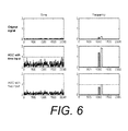
- the third example illustrated in Figure 6 shows the same situation as the previous one, now with transmission to another user on a higher frequency, illustrated by the right bar.
- the time domain signal now has higher amplitude, leading to a gain decrease from the AGC with a time domain signal input.
- the AGC with a frequency domain signal input looking at frequencies outside the current user's band, will notice the new transmission and decrease the gain.
- Another operation scenario is when the receiver impairments generate a high DC offset before the FFT. If the dynamic range is wide enough, this will only affect the DC sub-carrier, which often is not used for data transmission. However, having overflow in the FFT, the information can leak to other sub-carriers. To handle this scenario, the AGC can measure the DC output of the FFT, and do not need to measure the whole band, to save complexity.
- resource blocks If the users are assigned certain blocks of sub-carriers (resource blocks), complexity can be lowered by not viewing all individual sub-carriers within the resource block, but only one or a few.
- the intermediate results inside the FFT can also be used to distinguish if there is a too high value at DC or some other point. Looking inside the FFT may give faster results, and that overflow may occur inside the FFT while not being visible on the outside.
- time domain input to the AGC 208, although the frequency domain input now is added.
- Using the time domain signal can be done with low complexity, and can give a faster result due to the delay in the FFT 206.
- PAR Peak to Average Ratio
- a time domain input is suitable. The high PAR level, that may saturate the ADC, is not visible in the frequency domain.
- the signal path in the frequency domain can be more efficiently dimensioned when applying the invention. This will lead to a lower risk of overflow, or a less complex solution, due to that a smaller signal overhead now is needed.
- the invention does not only use pilot tones in the frequency domain, but possibly all sub-carriers that belong to the current user or other users in the same OFDM frame. This solution handles the multi-user case better, where different users each have a smaller frequency range within the OFDM frame.
- a portable or handheld mobile radio communication equipment or device may comprise the device 200.
- At least some parts of the method may be embedded in a computer program product, which enables implementation of the method steps and function described herein.
- the invention may be carried out when the computer program is loaded and run in an apparatus having computer capabilities.
- Computer program, software program, program product, or software in the present context mean any expression, in any programming language, code or notation, of a set of instructions intended to cause an apparatus having a processing capability to perform a particular function directly or after conversion to another language, code or notation.
- the invention also extends to programs on or in a carrier, adapted for putting the invention into practice.
- the program may be in the form of source code, object code a code suitable for use in the implementation of the method according to the invention.
- the carrier can be any entity or device capable of carrying the program.
- the carrier may be a record medium, computer memory, read-only memory or an electrical carrier signal.
Landscapes
- Engineering & Computer Science (AREA)
- Computer Networks & Wireless Communication (AREA)
- Signal Processing (AREA)
- Circuits Of Receivers In General (AREA)
- Control Of Amplification And Gain Control (AREA)
Priority Applications (5)
| Application Number | Priority Date | Filing Date | Title |
|---|---|---|---|
| EP07150377A EP2073473A1 (de) | 2007-12-21 | 2007-12-21 | Verfahren und Vorrichtung zur automatischen Verstärkungsregelung |
| CN200880123127.5A CN101904147B (zh) | 2007-12-21 | 2008-12-15 | 用于自动增益控制的方法和装置 |
| EP08865316.7A EP2235899B1 (de) | 2007-12-21 | 2008-12-15 | Verfahren und Vorrichtung zur automatischen Verstärkungsregelung |
| US12/809,710 US20100272219A1 (en) | 2007-12-21 | 2008-12-15 | Method and Device for Automatic Gain Control |
| PCT/EP2008/067502 WO2009080578A1 (en) | 2007-12-21 | 2008-12-15 | A method and device for automatic gain control |
Applications Claiming Priority (1)
| Application Number | Priority Date | Filing Date | Title |
|---|---|---|---|
| EP07150377A EP2073473A1 (de) | 2007-12-21 | 2007-12-21 | Verfahren und Vorrichtung zur automatischen Verstärkungsregelung |
Publications (1)
| Publication Number | Publication Date |
|---|---|
| EP2073473A1 true EP2073473A1 (de) | 2009-06-24 |
Family
ID=39399245
Family Applications (2)
| Application Number | Title | Priority Date | Filing Date |
|---|---|---|---|
| EP07150377A Withdrawn EP2073473A1 (de) | 2007-12-21 | 2007-12-21 | Verfahren und Vorrichtung zur automatischen Verstärkungsregelung |
| EP08865316.7A Not-in-force EP2235899B1 (de) | 2007-12-21 | 2008-12-15 | Verfahren und Vorrichtung zur automatischen Verstärkungsregelung |
Family Applications After (1)
| Application Number | Title | Priority Date | Filing Date |
|---|---|---|---|
| EP08865316.7A Not-in-force EP2235899B1 (de) | 2007-12-21 | 2008-12-15 | Verfahren und Vorrichtung zur automatischen Verstärkungsregelung |
Country Status (4)
| Country | Link |
|---|---|
| US (1) | US20100272219A1 (de) |
| EP (2) | EP2073473A1 (de) |
| CN (1) | CN101904147B (de) |
| WO (1) | WO2009080578A1 (de) |
Cited By (2)
| Publication number | Priority date | Publication date | Assignee | Title |
|---|---|---|---|---|
| EP2506593A1 (de) * | 2011-03-31 | 2012-10-03 | Sony Corporation | Empfänger, Empfangsverfahren, Programm und Empfangssystem zur Bestimmung einer Verstärkung und zum Einstellen der Leistung eines empfangenen Signals |
| CN114745026A (zh) * | 2022-04-12 | 2022-07-12 | 重庆邮电大学 | 一种基于深度饱和脉冲噪声的自动增益控制方法 |
Families Citing this family (12)
| Publication number | Priority date | Publication date | Assignee | Title |
|---|---|---|---|---|
| US8477887B2 (en) | 2009-12-21 | 2013-07-02 | Qualcomm Incorporated | Systems and methods providing frequency-domain automatic gain control (AGC) |
| CN102231905B (zh) * | 2011-06-20 | 2014-07-16 | 合肥东芯通信股份有限公司 | Lte系统的自动增益控制方法和设备 |
| US8854945B2 (en) * | 2011-11-09 | 2014-10-07 | Qualcomm Incorporated | Enhanced adaptive gain control in heterogeneous networks |
| CN103188787B (zh) * | 2011-12-31 | 2016-03-30 | 重庆重邮信科通信技术有限公司 | 一种自动增益控制方法及装置 |
| US8830859B2 (en) | 2012-05-10 | 2014-09-09 | Blackberry Limited | Power based gain control adjustment |
| US9479131B2 (en) * | 2014-05-23 | 2016-10-25 | Qualcomm Incorporated | Carrier aggregation amplifier with dual gain control |
| US10641901B2 (en) * | 2015-03-20 | 2020-05-05 | Qualcomm Incorporated | Autonomous satellite automatic gain control |
| CN106612533B (zh) * | 2015-10-26 | 2019-12-17 | 瑞昱半导体股份有限公司 | 通信接收端及其自动增益控制方法 |
| US9628122B1 (en) * | 2016-07-25 | 2017-04-18 | The Aerospace Corporation | Circuits and methods for reducing interference that spectrally overlaps a desired signal based on dynamic gain control and/or equalization |
| CN110535795B (zh) * | 2018-05-24 | 2021-11-05 | 中兴通讯股份有限公司 | 一种信号处理方法和装置 |
| CN112866162B (zh) * | 2021-01-05 | 2022-05-31 | 上海微波技术研究所(中国电子科技集团公司第五十研究所) | 基于时域和频域功率的自动增益控制方法、系统及介质 |
| CN116233992A (zh) * | 2023-05-08 | 2023-06-06 | 杰创智能科技股份有限公司 | 数字自动增益控制方法、装置、电子设备及存储介质 |
Citations (2)
| Publication number | Priority date | Publication date | Assignee | Title |
|---|---|---|---|---|
| WO2000079748A1 (en) * | 1999-06-23 | 2000-12-28 | At & T Wireless Services, Inc. | Automatic gain control for ofdm receiver |
| US20020186799A1 (en) * | 2001-04-03 | 2002-12-12 | Zulfiquar Sayeed | Method and apparatus for adjusting the gain of an if amplifier in a communication system |
Family Cites Families (5)
| Publication number | Priority date | Publication date | Assignee | Title |
|---|---|---|---|---|
| JP3599001B2 (ja) * | 2001-06-25 | 2004-12-08 | ソニー株式会社 | 自動利得制御回路およびその方法、並びにそれらを用いた復調装置 |
| US7088791B2 (en) * | 2001-10-19 | 2006-08-08 | Texas Instruments Incorporated | Systems and methods for improving FFT signal-to-noise ratio by identifying stage without bit growth |
| US8401128B2 (en) * | 2003-08-28 | 2013-03-19 | Telefonaktiebolaget L M Ericsson (Publ) | Method and system for adaptable receiver parameters |
| US20060182197A1 (en) * | 2005-02-14 | 2006-08-17 | Freescale Semiconductor, Inc. | Blind RF carrier feedthrough suppression in a transmitter |
| KR100668663B1 (ko) * | 2005-09-30 | 2007-01-12 | 한국전자통신연구원 | Ofdm 시스템에서 이동국의 자동이득제어 장치 및 방법 |
-
2007
- 2007-12-21 EP EP07150377A patent/EP2073473A1/de not_active Withdrawn
-
2008
- 2008-12-15 US US12/809,710 patent/US20100272219A1/en not_active Abandoned
- 2008-12-15 EP EP08865316.7A patent/EP2235899B1/de not_active Not-in-force
- 2008-12-15 CN CN200880123127.5A patent/CN101904147B/zh not_active Expired - Fee Related
- 2008-12-15 WO PCT/EP2008/067502 patent/WO2009080578A1/en active Application Filing
Patent Citations (2)
| Publication number | Priority date | Publication date | Assignee | Title |
|---|---|---|---|---|
| WO2000079748A1 (en) * | 1999-06-23 | 2000-12-28 | At & T Wireless Services, Inc. | Automatic gain control for ofdm receiver |
| US20020186799A1 (en) * | 2001-04-03 | 2002-12-12 | Zulfiquar Sayeed | Method and apparatus for adjusting the gain of an if amplifier in a communication system |
Cited By (4)
| Publication number | Priority date | Publication date | Assignee | Title |
|---|---|---|---|---|
| EP2506593A1 (de) * | 2011-03-31 | 2012-10-03 | Sony Corporation | Empfänger, Empfangsverfahren, Programm und Empfangssystem zur Bestimmung einer Verstärkung und zum Einstellen der Leistung eines empfangenen Signals |
| US8681904B2 (en) | 2011-03-31 | 2014-03-25 | Sony Corporation | Receiver, reception method, program and reception system |
| CN114745026A (zh) * | 2022-04-12 | 2022-07-12 | 重庆邮电大学 | 一种基于深度饱和脉冲噪声的自动增益控制方法 |
| CN114745026B (zh) * | 2022-04-12 | 2023-10-20 | 重庆邮电大学 | 一种基于深度饱和脉冲噪声的自动增益控制方法 |
Also Published As
| Publication number | Publication date |
|---|---|
| EP2235899A1 (de) | 2010-10-06 |
| CN101904147B (zh) | 2014-11-05 |
| US20100272219A1 (en) | 2010-10-28 |
| WO2009080578A1 (en) | 2009-07-02 |
| EP2235899B1 (de) | 2015-08-26 |
| CN101904147A (zh) | 2010-12-01 |
Similar Documents
| Publication | Publication Date | Title |
|---|---|---|
| EP2235899B1 (de) | Verfahren und Vorrichtung zur automatischen Verstärkungsregelung | |
| KR100933146B1 (ko) | 무선 통신 시스템에 대한 안테나 어레이 보정 | |
| US9130810B2 (en) | OFDM communications methods and apparatus | |
| US7715492B2 (en) | Transmitter and transmission method | |
| CN102231905B (zh) | Lte系统的自动增益控制方法和设备 | |
| US20080013646A1 (en) | Peak suppression control apparatus | |
| KR101727088B1 (ko) | 압축 센싱에 기초한 ofdm 변조-복조 방법, 장치 및 시스템 | |
| US20120257690A1 (en) | Orthogonal frequency division multiplexing (ofdm) | |
| US20140233676A1 (en) | Control method and equipment for radio-frequency signal | |
| KR20080000212A (ko) | 직교주파수분할다중접속 시스템의 레인징 채널 처리 장치및 방법 | |
| US10129063B2 (en) | Method and device for detecting signal of LTE uplink system in interference condition | |
| US20150043679A1 (en) | Ofdm modulated wave transmitter apparatus, ofdm modulated wave transmission method, and program | |
| CN107276957B (zh) | 信号处理电路 | |
| US11329794B2 (en) | Method and device for transmitting and receiving signal on basis of full duplex communication | |
| JP2002077097A (ja) | マルチキャリア伝送装置 | |
| CN104821856B (zh) | 一种用于ofdm频谱感知的噪声功率估计方法 | |
| US9124467B2 (en) | Receiver gain adjustment to reducing an influence of a DC offset | |
| US20060215537A1 (en) | Apparatus and method for estimating a clipping parameter of an ofdm system | |
| KR20040061016A (ko) | Ofdm 시스템들의 전력 증폭기 과도상태 보상 | |
| KR100638592B1 (ko) | Ofdm 시스템의 단말의 수신기용 dc 오프셋 제거 장치및 그 방법 | |
| KR101084550B1 (ko) | 첨두대평균 전력비 감소 방법, 첨두대평균 전력비 감소 장치, 송신기, 및 수신기 | |
| Singh et al. | Novel companding technique for PAPR reduction in OFDM system | |
| US8130866B2 (en) | Peak suppressing apparatus, peak suppressing method, and wireless communication device | |
| Smolnikar et al. | Impact of quantization on channel estimation in OFDM communication system | |
| CN111865846A (zh) | 一种干扰信号的信道影响估计分析方法 |
Legal Events
| Date | Code | Title | Description |
|---|---|---|---|
| PUAI | Public reference made under article 153(3) epc to a published international application that has entered the european phase |
Free format text: ORIGINAL CODE: 0009012 |
|
| AK | Designated contracting states |
Kind code of ref document: A1 Designated state(s): AT BE BG CH CY CZ DE DK EE ES FI FR GB GR HU IE IS IT LI LT LU LV MC MT NL PL PT RO SE SI SK TR |
|
| AX | Request for extension of the european patent |
Extension state: AL BA HR MK |
|
| AKX | Designation fees paid | ||
| REG | Reference to a national code |
Ref country code: DE Ref legal event code: 8566 |
|
| STAA | Information on the status of an ep patent application or granted ep patent |
Free format text: STATUS: THE APPLICATION IS DEEMED TO BE WITHDRAWN |
|
| 18D | Application deemed to be withdrawn |
Effective date: 20091229 |