EP2073325A1 - Optoelektrische Baugruppe mit frequenzverdoppeltem Festkörperlaser - Google Patents
Optoelektrische Baugruppe mit frequenzverdoppeltem Festkörperlaser Download PDFInfo
- Publication number
- EP2073325A1 EP2073325A1 EP08105890A EP08105890A EP2073325A1 EP 2073325 A1 EP2073325 A1 EP 2073325A1 EP 08105890 A EP08105890 A EP 08105890A EP 08105890 A EP08105890 A EP 08105890A EP 2073325 A1 EP2073325 A1 EP 2073325A1
- Authority
- EP
- European Patent Office
- Prior art keywords
- state laser
- solid
- frequency
- heat source
- doubled
- Prior art date
- Legal status (The legal status is an assumption and is not a legal conclusion. Google has not performed a legal analysis and makes no representation as to the accuracy of the status listed.)
- Granted
Links
Images
Classifications
-
- H—ELECTRICITY
- H01—ELECTRIC ELEMENTS
- H01S—DEVICES USING THE PROCESS OF LIGHT AMPLIFICATION BY STIMULATED EMISSION OF RADIATION [LASER] TO AMPLIFY OR GENERATE LIGHT; DEVICES USING STIMULATED EMISSION OF ELECTROMAGNETIC RADIATION IN WAVE RANGES OTHER THAN OPTICAL
- H01S3/00—Lasers, i.e. devices using stimulated emission of electromagnetic radiation in the infrared, visible or ultraviolet wave range
- H01S3/02—Constructional details
- H01S3/025—Constructional details of solid state lasers, e.g. housings or mountings
-
- H—ELECTRICITY
- H01—ELECTRIC ELEMENTS
- H01S—DEVICES USING THE PROCESS OF LIGHT AMPLIFICATION BY STIMULATED EMISSION OF RADIATION [LASER] TO AMPLIFY OR GENERATE LIGHT; DEVICES USING STIMULATED EMISSION OF ELECTROMAGNETIC RADIATION IN WAVE RANGES OTHER THAN OPTICAL
- H01S3/00—Lasers, i.e. devices using stimulated emission of electromagnetic radiation in the infrared, visible or ultraviolet wave range
- H01S3/02—Constructional details
- H01S3/04—Arrangements for thermal management
- H01S3/042—Arrangements for thermal management for solid state lasers
-
- H—ELECTRICITY
- H01—ELECTRIC ELEMENTS
- H01S—DEVICES USING THE PROCESS OF LIGHT AMPLIFICATION BY STIMULATED EMISSION OF RADIATION [LASER] TO AMPLIFY OR GENERATE LIGHT; DEVICES USING STIMULATED EMISSION OF ELECTROMAGNETIC RADIATION IN WAVE RANGES OTHER THAN OPTICAL
- H01S3/00—Lasers, i.e. devices using stimulated emission of electromagnetic radiation in the infrared, visible or ultraviolet wave range
- H01S3/005—Optical devices external to the laser cavity, specially adapted for lasers, e.g. for homogenisation of the beam or for manipulating laser pulses, e.g. pulse shaping
- H01S3/0092—Nonlinear frequency conversion, e.g. second harmonic generation [SHG] or sum- or difference-frequency generation outside the laser cavity
-
- H—ELECTRICITY
- H01—ELECTRIC ELEMENTS
- H01S—DEVICES USING THE PROCESS OF LIGHT AMPLIFICATION BY STIMULATED EMISSION OF RADIATION [LASER] TO AMPLIFY OR GENERATE LIGHT; DEVICES USING STIMULATED EMISSION OF ELECTROMAGNETIC RADIATION IN WAVE RANGES OTHER THAN OPTICAL
- H01S3/00—Lasers, i.e. devices using stimulated emission of electromagnetic radiation in the infrared, visible or ultraviolet wave range
- H01S3/02—Constructional details
- H01S3/04—Arrangements for thermal management
- H01S3/0401—Arrangements for thermal management of optical elements being part of laser resonator, e.g. windows, mirrors, lenses
-
- H—ELECTRICITY
- H01—ELECTRIC ELEMENTS
- H01S—DEVICES USING THE PROCESS OF LIGHT AMPLIFICATION BY STIMULATED EMISSION OF RADIATION [LASER] TO AMPLIFY OR GENERATE LIGHT; DEVICES USING STIMULATED EMISSION OF ELECTROMAGNETIC RADIATION IN WAVE RANGES OTHER THAN OPTICAL
- H01S3/00—Lasers, i.e. devices using stimulated emission of electromagnetic radiation in the infrared, visible or ultraviolet wave range
- H01S3/02—Constructional details
- H01S3/04—Arrangements for thermal management
- H01S3/0405—Conductive cooling, e.g. by heat sinks or thermo-electric elements
-
- H—ELECTRICITY
- H01—ELECTRIC ELEMENTS
- H01S—DEVICES USING THE PROCESS OF LIGHT AMPLIFICATION BY STIMULATED EMISSION OF RADIATION [LASER] TO AMPLIFY OR GENERATE LIGHT; DEVICES USING STIMULATED EMISSION OF ELECTROMAGNETIC RADIATION IN WAVE RANGES OTHER THAN OPTICAL
- H01S3/00—Lasers, i.e. devices using stimulated emission of electromagnetic radiation in the infrared, visible or ultraviolet wave range
- H01S3/10—Controlling the intensity, frequency, phase, polarisation or direction of the emitted radiation, e.g. switching, gating, modulating or demodulating
- H01S3/102—Controlling the intensity, frequency, phase, polarisation or direction of the emitted radiation, e.g. switching, gating, modulating or demodulating by controlling the active medium, e.g. by controlling the processes or apparatus for excitation
- H01S3/1028—Controlling the intensity, frequency, phase, polarisation or direction of the emitted radiation, e.g. switching, gating, modulating or demodulating by controlling the active medium, e.g. by controlling the processes or apparatus for excitation by controlling the temperature
Definitions
- the invention relates to an optoelectrical assembly with a frequency-doubled solid-state laser, in particular a diode-pumped solid-state laser (DPSS) with neobdym-doped yttrium orthovadanate (Nb: YVO4), whose IR laser beam of 1064 nm by means of an optically nonlinear crystal of potassium titanyl phosphate (KTP) within the optical resonator is doubled in the green spectral range of 532nm for use in optoelectic marking systems such as construction lasers.
- DPSS diode-pumped solid-state laser
- KTP potassium titanyl phosphate
- Optoelectic marking systems are used in monomode operation (TEM00), in which the exiting, frequency-doubled laser beam has only exactly one spatial energy maximum, which thus results in exactly one round light spot when hitting a reflective target object.
- TEM00 monomode operation
- the exiting, frequency-doubled laser beam has only exactly one spatial energy maximum, which thus results in exactly one round light spot when hitting a reflective target object.
- different operating modes can be excited.
- these frequency doubled solid state lasers are specified for an operating temperature of 15 ° C to 30 ° C.
- the optical resonator After US5495489 is combined in an opto-electrical module with a modular frequency-doubled solid state laser, the optical resonator with a coaxially circulating heat source and controlled by a control means to an operating temperature near 30 ° C, ie depending on the design case for different ambient temperatures additionally heated and cooled by Peltier elements, or opposite the ambient temperature only cooled or just heated.
- the optical resonator is arranged coaxially within the controllable heat source, which itself is surrounded radially outside of a coaxial heat sink with cooling fins.
- the object is the technologically simple realization of an opto-electrical module with a stable in monomode operation frequency-doubled solid state laser for an ambient temperature range of -20 ° C to + 45 ° C.
- a further aspect is the suitable adjustment of the optical axis of the frequency-doubled solid-state laser within the optoelectrical assembly.
- an optoelectrical assembly has a set therein adjusted, modular frequency-doubled solid-state laser with an optical resonator, which is thermally conductively connected to a controllable by a control means heat source, wherein the operating temperature of the solid-state laser is set by the control means between 40 ° C and 55 ° C.
- the solid-state laser Due to the unusual and energetically uneconomical high operating temperature of the solid-state laser can be dispensed with in the ambient temperature range of -20 ° C to + 45 ° C to an active cooling, whereby for the controllable heat source (compared to a Peltier element) simpler and thus more cost-effective controllable heating means is sufficient.
- the heat source can also be used as a temperature sensor at the same time.
- the heating means is a (self-adhesive) heating foil, which further advantageously surrounds the optical resonator circumferentially, as a result of which it can be mounted in a technologically simple manner in the region of the optical resonator of the modular frequency-doubled solid-state laser.
- the solid-state laser is embedded in the optoelectrical assembly via a hardenable potting compound with a thermal conductivity in the range of 0.1 to 1.0 W / (Km), whereby the potting compound defines a heat flow (for cooling by the always lower ambient temperature) and a simple heat flow radial and axial adjustment of the solid-state laser in the opto-electrical assembly in a technologically simple manner combines in itself.
- the potting compound of gypsum which is further advantageously provided with additives such as metal shavings, whereby both the thermal conductivity and the curing time is adjustable in suitable areas.
- an axially sealing sealing means is arranged between the modular solid-state laser and the radially surrounding optoelectric assembly, whereby this (in the optical adjustment below) prevents the still viscous potting compound from flowing away and the optical adjustment thus becomes technologically simple.
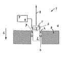
- an optoelectrical assembly 1 has a modular, frequency-doubled solid-state laser 2 in the form of a diode-pumped solid-state laser (DPSS) doped with neobdym-doped yttrium orthovadanate (Nb: YVO4) whose IR laser beam of 1064 nm is formed by means of an optically nonlinear crystal Potassium titanyl phosphate (KTP) within an optical resonator 3 is frequency doubled in the green spectral range of 532nm and emits a focused green laser beam 8.
- DPSS diode-pumped solid-state laser
- Nb neobdym-doped yttrium orthovadanate
- KTP optically nonlinear crystal Potassium titanyl phosphate
- the spatial region of the optical resonator 3 in the modular solid-state laser 2 is thermally conductively connected to a heat source 5 which can be controlled by a control means 4 in the form of a microcontroller in the form of a self-adhesive heating foil.
- a control means 4 in the form of a microcontroller in the form of a self-adhesive heating foil.
- the temperature-dependent resistance of the surrounding the optical resonator 3 heating foil serves the control means 4 at the same time as a temperature sensor.
- an axially sealing sealant 6 is arranged, which seals the resulting annulus to the radially surrounding opto-electrical assembly 1 in the direction of gravity G during the adjustment.
- a thermal conductivity [lambda] of 0.1 to 1.0 W / (Km) (thermal conductivity [lambda] of the metal chips between about 10 to 100 W / ( Km)) the solid-state laser 2 is embedded axially and radially adjusted in the radially surrounding optoelectronic assembly 1.
- the thermal conductivity [lambda] of 0.1 to 1.0 W / (Km) of the potting compound 7 is defined by metal swarf as the essential part of the heat flow from the heat source 5 and the solid-state laser 2 to passively cooled by the ambient temperature U of 45 ° Holder 9 made of metal of the opto-electrical module 1.
Landscapes
- Physics & Mathematics (AREA)
- Electromagnetism (AREA)
- Engineering & Computer Science (AREA)
- Plasma & Fusion (AREA)
- Optics & Photonics (AREA)
- Lasers (AREA)
- Optical Modulation, Optical Deflection, Nonlinear Optics, Optical Demodulation, Optical Logic Elements (AREA)
Abstract
Überschüssige Wärme der Optoelektrischen Baugruppe (1) wird über eine Vergussmasse (7) an die passiv gekühlthe Metallhalterung (9) abgegeben, wobei ein axiales Dichtmittel (6) zur Fixierung der Baugruppe dient.
Description
- Die Erfindung bezeichnet eine optoelektrische Baugruppe mit einem frequenzverdoppelten Festkörperlaser, insbesondere einem diodengepumpten Festkörperlaser (DPSS) mit Neobdym dotiertem Yttrium-Orthovadanat (Nb:YVO4), dessen IR-Laserstrahl von 1064nm mittels eines optisch nichtlinearen Kristalls aus Kalium-Titanyl-Phosphat (KTP) innerhalb des optischen Resonators in den grünen Spektralbereich von 532nm frequenzverdoppelt wird, zur Verwendung in optoelektischen Markiersystemen wie Baulasern.
- Optoelektische Markiersysteme werden im monomode-Betrieb (TEM00) verwendet, bei welcher der austretende, frequenzverdoppelte Laserstrahl nur genau ein räumliches Energiemaximum aufweist, welches somit beim Auftreffen auf ein reflektierendes Zielobjekt genau einen runden Leuchtfleck ergibt. In dem optisch nichtlinearen Kristall können jedoch abhängig von den Randbedingungen, insbesondere der Umgebungstemperatur, verschiedene Betriebs-Moden angeregt werden. Üblicherweise sind diese frequenzverdoppelten Festkörperlaser auf eine Betriebstemperatur von 15°C bis 30°C spezifiziert.
- Nach der
US5495489 wird bei einer optoelektrischen Baugruppe mit einem modularen frequenzverdoppelten Festkörperlaser der optische Resonator mit einer koaxial umlaufenden Wärmequelle kombiniert und mit einem Steuermittel auf eine Betriebstemperatur nahe 30°C geregelt, d.h. je nach Auslegungsfall für unterschiedliche Umgebungstemperaturen zusätzlich über Peltier-Elemente geheizt und gekühlt, oder gegenüber der Umgebungstemperatur nur gekühlt oder nur geheizt. Dabei ist der optische Resonator koaxial innerhalb der steuerbaren Wärmequelle angeordnet, die selbst radial aussen von einer koaxialen Wärmesenke mit Kühlrippen umgeben ist. - Die Aufgabe besteht in der technologisch einfachen Realisierung einer optoelektrischen Baugruppe mit einem im monomode-Betrieb stabilen frequenzverdoppelten Festkörperlaser für einen Umgebungstemperaturbereich von -20°C bis +45°C. Ein weiterer Aspekt besteht in der geeigneten Justage der optischen Achse des frequenzverdoppelten Festkörperlasers innerhalb der optoelektrischen Baugruppe.
- Die Aufgabe wird im Wesentlichen durch die Merkmale des Anspruchs 1 gelöst. Vorteilhafte Weiterbildungen ergeben sich aus den Unteransprüchen.
- So weist eine optoelektrische Baugruppe einen darin justiert festgelegten, modularen frequenzverdoppelten Festkörperlaser mit einem optischen Resonator auf, der wärmeleitend mit einer von einem Steuermittel steuerbaren Wärmequelle verbunden ist, wobei die Betriebstemperatur des Festkörperlasers über das Steuermittel zwischen 40°C und 55°C eingestellt ist.
- Durch die unübliche und energetisch unökonomische hohe Betriebstemperatur des Festkörperlasers kann auch im Umgebungstemperaturbereich von -20°C bis +45°C auf eine aktive Kühlung verzichtet werden, wodurch für die steuerbare Wärmequelle ein (gegenüber einem Peltier-Element) einfacheres und somit kostengünstigeres steuerbares Heizmittel hinreichend ist. Im Falle eines temperaturabhängigen Widerstands kann die Wärmequelle zugleich auch als Temperatursensor verwendet werden.
- Vorteilhaft ist das Heizmittel eine (selbstklebende) Heizfolie, die weiter vorteilhaft den optischen Resonator umlaufend umgibt, wodurch diese technologisch einfach im Bereich des optischen Resonators des modularen frequenzverdoppelten Festkörperlasers montierbar ist.
- Vorteilhaft ist der Festkörperlaser über eine aushärtbare Vergussmasse mit einer Wärmeleitfähigkeit im Bereich von 0,1 bis 1,0 W/(Km) in die optoelektrische Baugruppe eingebettet, wodurch die Vergussmasse einen (zur Kühlung durch die stets niedrigere Umgebungstemperatur) definierten Wärmefluss sowie eine einfache radiale und axiale Justage des Festkörperlasers in der optoelektrischen Baugruppe in technologisch einfacher Weise in sich vereint.
- Vorteilhaft besteht die Vergussmasse aus Gips, welches weiter vorteilhaft mit Additiven wie Metallspänen versehen ist, wodurch sowohl die Wärmeleitfähigkeit als auch die Aushärtzeit in geeigneten Bereichen einstellbar ist.
- Vorteilhaft ist zwischen dem modularen Festkörperlaser und der radial umgebenden optoelektrischen Baugruppe ein axial dichtendes Dichtmittel angeordnet, wodurch dies (bei der optischen Justage unten angeordnet) ein Wegfliessen der noch zähflüssigen Vergussmasse verhindert und die optische Justage somit technologisch einfach wird.
- Die Erfindung wird bezüglich eines vorteilhaften Ausführungsbeispiels näher erläutert mit einer Darstellung einer optoelektrischen Baugruppe.
- Nach der Darstellung weist eine optoelektrische Baugruppe 1 einen darin justiert festgelegten, modularen frequenzverdoppelten Festkörperlaser 2 in Form eines diodengepumpten Festkörperlasers (DPSS) mit Neobdym dotiertem Yttrium-Orthovadanat (Nb:YVO4) auf, dessen IR-Laserstrahl von 1064nm mittels eines optisch nichtlinearen Kristalls aus Kalium-Titanyl-Phosphat (KTP) innerhalb eines optischen Resonators 3 in den grünen Spektralbereich von 532nm frequenzverdoppelt wird und einen fokussierten grünen Laserstrahl 8 aussendet. Der Raumbereich des optischen Resonators 3 im modularen Festkörperlaser 2 ist wärmeleitend mit einer von einem Steuermittel 4 in Form eines Mikrocontrollers steuerbaren Wärmequelle 5 in Form einer selbstklebenden Heizfolie verbunden. Dabei dient der temperaturabhängige Widerstand der den optischen Resonator 3 umlaufend umgebenden Heizfolie dem Steuermittel 4 gleichzeitig als Temperatursensor. Indem im Steuermittel 4 als Sollwert eine Betriebstemperatur T von 50°C programmiert ist, wird der Festkörperlaser 2 (nach der Initialisierung des Temperaturregelkreises) auch bei einer Betriebstemperatur T von 50°C betrieben. Zwischen dem modularen Festkörperlaser 2 und der radial umgebenden optoelektrischen Baugruppe 1 ist ein axial dichtendes Dichtmittel 6 angeordnet, welches bei der Justage den entstehenden Ringraum zur radial umgebenden optoelektrischen Baugruppe 1 in Richtung der Schwerkraft G abdichtet. Nach der Aushärtung einer in diesen Ringraum eingefüllten aushärtbaren Vergussmasse 7 aus Gips mit Metallspänen mit einer Wärmeleitfähigkeit [lambda] von 0,1 bis 1,0 W/(Km) (Wärmeleitfähigkeit [lambda] der Metallspäne zwischen ca. 10 bis 100 W/(Km)) ist der Festkörperlaser 2 in die radial umgebende optoelektrische Baugruppe 1 axial und radial justiert eingebettet. Über die mit Metallspänen definiert eingestellte Wärmeleitfähigkeit [lambda] von 0,1 bis 1,0 W/(Km) der Vergussmasse 7 erfolgt der wesentliche Teil des Wärmeflusses von der Wärmequelle 5 und dem Festkörperlaser 2 zur durch die Umgebungstemperatur U von 45° passiv gekühlten Halterung 9 aus Metall der optoelektrischen Baugruppe 1.
Claims (5)
- Optoelektrische Baugruppe mit einem darin justiert festgelegten, modularen frequenzverdoppelten Festkörperlaser (2) mit einem optischen Resonator (3), der wärmeleitend mit einer von einem Steuermittel (4) steuerbaren Wärmequelle (5) verbunden ist, dadurch gekennzeichnet, dass die Betriebstemperatur (T) des Festkörperlasers (2) über das Steuermittel (4) zwischen 40°C und 55°C eingestellt ist.
- Optoelektrische Baugruppe nach Anspruch 1, dadurch gekennzeichnet, dass die Wärmequelle (5) eine Heizfolie ist.
- Optoelektrische Baugruppe nach Anspruch 1 oder 2, dadurch gekennzeichnet, dass der Festkörperlaser (2) über eine aushärtbare Vergussmasse (7) mit einer Wärmeleitfähigkeit ([lambda]) im Bereich von 0,1 bis 1,0 W/(Km) eingebettet ist.
- Optoelektrische Baugruppe nach Anspruch 3, dadurch gekennzeichnet, dass die Vergussmasse (7) aus Gips besteht.
- Optoelektrische Baugruppe nach einem der Ansprüche 1 bis 4, dadurch gekennzeichnet, dass an dem modularen Festkörperlaser (2) ein axial dichtendes Dichtmittel (6) angeordnet ist.
Applications Claiming Priority (1)
| Application Number | Priority Date | Filing Date | Title |
|---|---|---|---|
| DE102007055848A DE102007055848A1 (de) | 2007-12-18 | 2007-12-18 | Optoelektrische Baugruppe mit frequenzverdoppeltem Festkörperlaser |
Publications (2)
| Publication Number | Publication Date |
|---|---|
| EP2073325A1 true EP2073325A1 (de) | 2009-06-24 |
| EP2073325B1 EP2073325B1 (de) | 2012-09-12 |
Family
ID=40361381
Family Applications (1)
| Application Number | Title | Priority Date | Filing Date |
|---|---|---|---|
| EP08105890A Active EP2073325B1 (de) | 2007-12-18 | 2008-11-28 | Optoelektrische Baugruppe mit einem frequenzverdoppelten Festkörperlaser |
Country Status (5)
| Country | Link |
|---|---|
| US (1) | US20090154510A1 (de) |
| EP (1) | EP2073325B1 (de) |
| JP (1) | JP2009151301A (de) |
| CN (1) | CN101465514A (de) |
| DE (1) | DE102007055848A1 (de) |
Families Citing this family (1)
| Publication number | Priority date | Publication date | Assignee | Title |
|---|---|---|---|---|
| DE102019116113A1 (de) * | 2019-06-13 | 2020-12-17 | Jenoptik Optical Systems Gmbh | Passiv gütegeschalteter Festkörperlaser |
Citations (7)
| Publication number | Priority date | Publication date | Assignee | Title |
|---|---|---|---|---|
| GB191420179A (en) * | 1914-09-25 | 1915-03-25 | Richard Keyworth Roach | Improvements in and relating to Combined Spirit Levels and Plumb Bobs. |
| JPS5922382A (ja) * | 1982-07-29 | 1984-02-04 | Canon Inc | 半導体レ−ザ装置 |
| US5253259A (en) * | 1991-02-07 | 1993-10-12 | Matsushita Electric Industrial Co., Ltd. | Frequency doubler and visible laser source having a heater |
| US5267252A (en) * | 1991-08-30 | 1993-11-30 | Hoya Corporation | Solid-state laser device comprising a temperature-controlled thermal conductive support |
| US5495489A (en) | 1994-05-07 | 1996-02-27 | Samsung Electronics Co., Ltd. | Second harmonic generating method and apparatus |
| US5754287A (en) * | 1997-01-06 | 1998-05-19 | Clarke; Douglas A. | Beam projecting plumb apparatus |
| US6177987B1 (en) * | 1998-02-26 | 2001-01-23 | Chih-Yu Ting | Laser level |
Family Cites Families (3)
| Publication number | Priority date | Publication date | Assignee | Title |
|---|---|---|---|---|
| US5187714A (en) * | 1990-10-19 | 1993-02-16 | Fuji Photo Film Co., Ltd. | Laser-diode-pumped solid-state laser |
| US5854802A (en) * | 1996-06-05 | 1998-12-29 | Jin; Tianfeng | Single longitudinal mode frequency converted laser |
| US6359918B1 (en) * | 1998-06-30 | 2002-03-19 | Honeywell International Inc. | Light source control device |
-
2007
- 2007-12-18 DE DE102007055848A patent/DE102007055848A1/de not_active Withdrawn
-
2008
- 2008-11-28 EP EP08105890A patent/EP2073325B1/de active Active
- 2008-12-11 CN CN200810184632.2A patent/CN101465514A/zh active Pending
- 2008-12-12 JP JP2008316755A patent/JP2009151301A/ja active Pending
- 2008-12-17 US US12/317,007 patent/US20090154510A1/en not_active Abandoned
Patent Citations (7)
| Publication number | Priority date | Publication date | Assignee | Title |
|---|---|---|---|---|
| GB191420179A (en) * | 1914-09-25 | 1915-03-25 | Richard Keyworth Roach | Improvements in and relating to Combined Spirit Levels and Plumb Bobs. |
| JPS5922382A (ja) * | 1982-07-29 | 1984-02-04 | Canon Inc | 半導体レ−ザ装置 |
| US5253259A (en) * | 1991-02-07 | 1993-10-12 | Matsushita Electric Industrial Co., Ltd. | Frequency doubler and visible laser source having a heater |
| US5267252A (en) * | 1991-08-30 | 1993-11-30 | Hoya Corporation | Solid-state laser device comprising a temperature-controlled thermal conductive support |
| US5495489A (en) | 1994-05-07 | 1996-02-27 | Samsung Electronics Co., Ltd. | Second harmonic generating method and apparatus |
| US5754287A (en) * | 1997-01-06 | 1998-05-19 | Clarke; Douglas A. | Beam projecting plumb apparatus |
| US6177987B1 (en) * | 1998-02-26 | 2001-01-23 | Chih-Yu Ting | Laser level |
Also Published As
| Publication number | Publication date |
|---|---|
| CN101465514A (zh) | 2009-06-24 |
| DE102007055848A1 (de) | 2009-07-09 |
| JP2009151301A (ja) | 2009-07-09 |
| EP2073325B1 (de) | 2012-09-12 |
| US20090154510A1 (en) | 2009-06-18 |
Similar Documents
| Publication | Publication Date | Title |
|---|---|---|
| DE69905829T2 (de) | Lasersystem mit phasenveränderlichem Material zur Temperatursteuerung | |
| DE60009348T2 (de) | Energie-effiziente, laser-basierte verfahren und vorrichtung zur verarbeitung von materialtarget | |
| DE3787676T2 (de) | Festkörperlaser. | |
| WO2005028856A1 (de) | Brennkraftmaschine | |
| EP2041847A2 (de) | Festkörperlaser mit einem monolithisch aufgebauten resonator | |
| EP1034584B1 (de) | Kühlvorrichtung für einen optischen kristall bzw. laserkristall | |
| DE102012106948A1 (de) | Femtosekundenlaservorrichtung unter Verwendung eines optischen Laserdioden-Pumpmodul | |
| DE19949198A1 (de) | Vorrichtung mit mindestens einer mehrere Einzel-Lichtquellen umfassenden Lichtquelle | |
| DE102013211977B3 (de) | Festkörperlaseranordnung | |
| EP1519038B1 (de) | Laser-Zündeinrichtung für eine Brennkraftmaschine | |
| DE19934638B4 (de) | Modensynchronisierter Festkörperlaser mit mindestens einem konkaven Faltungsspiegel | |
| DE10308597A1 (de) | Verbund-Laserstab, Verfahren zur Herstellung und damit ausgerüstete Laservorrichtung | |
| DE112021003639T5 (de) | Stufen-kern-faserstrukturen und verfahren zur veränderung von strahlform und intensität | |
| EP2073325B1 (de) | Optoelektrische Baugruppe mit einem frequenzverdoppelten Festkörperlaser | |
| DE69737538T2 (de) | Lasergerät | |
| DE102011082772B3 (de) | Verfahren zum Einleiten von Schutzgas in ein Absorberrohr | |
| DE102017217794B4 (de) | Laseroszillator | |
| DE102008061309A1 (de) | Diodenlaserbauelement | |
| Kleinbauer et al. | 80 W ultrafast CPA-free disk laser | |
| DE102013223109B4 (de) | Optikanordnung | |
| US9698561B1 (en) | Temperature tuned conjugated polymer laser | |
| WO2008061516A1 (de) | Verfahren und vorrichtung zum verändern des strahldurchmessers eines durch ein optisches element hindurchgehenden laserstrahls mittels temperaturänderung | |
| DE102019116113A1 (de) | Passiv gütegeschalteter Festkörperlaser | |
| WO2004027943A1 (de) | Optisch gepumpter festkörperlaser | |
| WO2015117727A1 (de) | Anordnung mit einem verstärkenden lasermaterial und einer kühleinheit |
Legal Events
| Date | Code | Title | Description |
|---|---|---|---|
| PUAI | Public reference made under article 153(3) epc to a published international application that has entered the european phase |
Free format text: ORIGINAL CODE: 0009012 |
|
| AK | Designated contracting states |
Kind code of ref document: A1 Designated state(s): AT BE BG CH CY CZ DE DK EE ES FI FR GB GR HR HU IE IS IT LI LT LU LV MC MT NL NO PL PT RO SE SI SK TR |
|
| AX | Request for extension of the european patent |
Extension state: AL BA MK RS |
|
| 17P | Request for examination filed |
Effective date: 20091228 |
|
| 17Q | First examination report despatched |
Effective date: 20100125 |
|
| AKX | Designation fees paid |
Designated state(s): CH DE FR GB IT LI |
|
| GRAP | Despatch of communication of intention to grant a patent |
Free format text: ORIGINAL CODE: EPIDOSNIGR1 |
|
| GRAS | Grant fee paid |
Free format text: ORIGINAL CODE: EPIDOSNIGR3 |
|
| GRAA | (expected) grant |
Free format text: ORIGINAL CODE: 0009210 |
|
| AK | Designated contracting states |
Kind code of ref document: B1 Designated state(s): CH DE FR GB IT LI |
|
| REG | Reference to a national code |
Ref country code: GB Ref legal event code: FG4D Free format text: NOT ENGLISH |
|
| REG | Reference to a national code |
Ref country code: CH Ref legal event code: EP |
|
| REG | Reference to a national code |
Ref country code: DE Ref legal event code: R096 Ref document number: 502008008151 Country of ref document: DE Effective date: 20121108 |
|
| PLBE | No opposition filed within time limit |
Free format text: ORIGINAL CODE: 0009261 |
|
| STAA | Information on the status of an ep patent application or granted ep patent |
Free format text: STATUS: NO OPPOSITION FILED WITHIN TIME LIMIT |
|
| 26N | No opposition filed |
Effective date: 20130613 |
|
| REG | Reference to a national code |
Ref country code: DE Ref legal event code: R097 Ref document number: 502008008151 Country of ref document: DE Effective date: 20130613 |
|
| REG | Reference to a national code |
Ref country code: FR Ref legal event code: PLFP Year of fee payment: 8 |
|
| REG | Reference to a national code |
Ref country code: FR Ref legal event code: PLFP Year of fee payment: 9 |
|
| REG | Reference to a national code |
Ref country code: FR Ref legal event code: PLFP Year of fee payment: 10 |
|
| REG | Reference to a national code |
Ref country code: CH Ref legal event code: U11 Free format text: ST27 STATUS EVENT CODE: U-0-0-U10-U11 (AS PROVIDED BY THE NATIONAL OFFICE) Effective date: 20251201 |
|
| PGFP | Annual fee paid to national office [announced via postgrant information from national office to epo] |
Ref country code: DE Payment date: 20251119 Year of fee payment: 18 |
|
| PGFP | Annual fee paid to national office [announced via postgrant information from national office to epo] |
Ref country code: GB Payment date: 20251121 Year of fee payment: 18 |
|
| PGFP | Annual fee paid to national office [announced via postgrant information from national office to epo] |
Ref country code: IT Payment date: 20251125 Year of fee payment: 18 |
|
| PGFP | Annual fee paid to national office [announced via postgrant information from national office to epo] |
Ref country code: FR Payment date: 20251121 Year of fee payment: 18 |
|
| PGFP | Annual fee paid to national office [announced via postgrant information from national office to epo] |
Ref country code: CH Payment date: 20251201 Year of fee payment: 18 |