EP2073066A1 - Belt device and image forming apparatus - Google Patents
Belt device and image forming apparatus Download PDFInfo
- Publication number
- EP2073066A1 EP2073066A1 EP08170759A EP08170759A EP2073066A1 EP 2073066 A1 EP2073066 A1 EP 2073066A1 EP 08170759 A EP08170759 A EP 08170759A EP 08170759 A EP08170759 A EP 08170759A EP 2073066 A1 EP2073066 A1 EP 2073066A1
- Authority
- EP
- European Patent Office
- Prior art keywords
- belt
- roller
- intermediate transfer
- unit
- belt device
- Prior art date
- Legal status (The legal status is an assumption and is not a legal conclusion. Google has not performed a legal analysis and makes no representation as to the accuracy of the status listed.)
- Granted
Links
Images



Classifications
-
- G—PHYSICS
- G03—PHOTOGRAPHY; CINEMATOGRAPHY; ANALOGOUS TECHNIQUES USING WAVES OTHER THAN OPTICAL WAVES; ELECTROGRAPHY; HOLOGRAPHY
- G03G—ELECTROGRAPHY; ELECTROPHOTOGRAPHY; MAGNETOGRAPHY
- G03G15/00—Apparatus for electrographic processes using a charge pattern
- G03G15/75—Details relating to xerographic drum, band or plate, e.g. replacing, testing
- G03G15/754—Details relating to xerographic drum, band or plate, e.g. replacing, testing relating to band, e.g. tensioning
- G03G15/755—Details relating to xerographic drum, band or plate, e.g. replacing, testing relating to band, e.g. tensioning for maintaining the lateral alignment of the band
-
- G—PHYSICS
- G03—PHOTOGRAPHY; CINEMATOGRAPHY; ANALOGOUS TECHNIQUES USING WAVES OTHER THAN OPTICAL WAVES; ELECTROGRAPHY; HOLOGRAPHY
- G03G—ELECTROGRAPHY; ELECTROPHOTOGRAPHY; MAGNETOGRAPHY
- G03G2215/00—Apparatus for electrophotographic processes
- G03G2215/00135—Handling of parts of the apparatus
- G03G2215/00139—Belt
- G03G2215/00143—Meandering prevention
- G03G2215/00156—Meandering prevention by controlling drive mechanism
Definitions
- the present invention relates to a belt device capable of correcting a meandering of a belt, such as an intermediate transfer belt, a conveying belt, or a photosensitive element belt, and an image forming apparatus including the belt device.
- a tandem-type color image forming apparatus including an intermediate transfer belt for example, as disclosed in Japanese Patent Application Laid-open No. 2006-343629 and Japanese Patent Application Laid-open No. 2001-38340 ) has been commonly used.
- tandem-type color image forming apparatus four photosensitive drums as image carriers are tandemly arranged to be opposed to an intermediate transfer belt.
- the image forming apparatus forms a full-color image in such a manner that black (K), yellow (Y), magenta (M), and cyan (C) toner images are formed on the photosensitive drums, respectively.
- K, Y, M, and C toner images formed on the photosensitive drums are sequentially transferred onto the intermediate transfer belt in a superimposed manner.
- the superimposed toner image transferred onto the intermediate transfer belt is further transferred onto a recording medium, and thereby forming a full-color image.
- an image forming apparatus as disclosed in Japanese Patent Application Laid-open No. 2006-343629 and Japanese Patent Application Laid-open No. 2001-38340 is configured to detect a displacement of an intermediate transfer belt in a width direction. Therefore, the image forming apparatus can correct a meandering of the intermediate transfer belt (the displacement in the width direction) based on a result of the detection.
- a displacement sensor detects an amount of displacement of a contact that is in contact with an edge portion of the intermediate transfer belt (an endless belt).
- the contact oscillates along with the meandering of the intermediate transfer belt, so that the meandering of the intermediate transfer belt can be detected based on a result of the detection by the displacement sensor.
- the meandering of the intermediate transfer belt is corrected by a meandering correction roller, which is one of rollers supporting the intermediate transfer belt, based on the amount of the displacement of the contact. More specifically, an oscillating arm connected to the meandering correction roller is moved by a movement of an eccentric cam to change the tilt of a rotating shaft of the meandering correction roller, and thereby correcting the meandering of the intermediate transfer belt.
- a meandering of a conveying belt (a transfer-medium conveying belt) is corrected in such a manner that a supporting arm connected to a tension applying roller, which is one of rollers supporting the conveying belt, is moved by a movement of a cam to change the tilt of a rotating shaft of the tension applying roller.
- an alignment of a steering roller for correcting a meandering of an endless belt can be manually adjusted.
- the above conventional technologies have problems.
- the apparatus is caused to stop operation because it is determined that a control error occurs when a meandering of the intermediate transfer belt is not corrected within a predetermined time; and a meandering of the intermediate transfer belt cannot be sufficiently corrected within a travel range of the meandering correction roller, i.e., the meandering correction roller cannot be moved enough to correct the meandering of the intermediate transfer belt because of the limitation of the travel range.
- Such problems are caused, for example, because a plurality of roller members supporting the intermediate transfer belt is installed in the belt device in a state where the parallelism of the roller members is not sufficiently maintained, a frame that rotatably supports the roller members is distorted, or the straightness of the roller members is not sufficiently maintained, so that a default position of the meandering correction roller is significantly deviated in either a forward direction or a backward direction away from a center position of the travel range.
- the above problems are not limited to a belt device employing an intermediate transfer belt as a belt member, but are common issues among belt devices that correct a meandering of a belt member regardless of a type of the belt member.
- a belt device including a belt member that is supported by a plurality of rollers and moves in a predetermined moving direction; a detecting unit that detects a displacement of the belt member in its width direction; a correcting unit that moves a second end of a first roller from among the rollers in either one of a forward direction and a backward direction while fixing its first end based on a result of detecting the displacement of the belt member such that a tilt of a rotating shaft of the first roller is changed to correct a meandering of the belt member; and an adjusting unit that adjusts a fixing position of the first end.
- Fig. 1 is a side view of a printer 100 as the image forming apparatus according to the embodiment of the present invention.
- the printer 100 includes a belt device 15, process units 6Y, 6M, 6C, and 6K, an exposure unit 7, a secondary transfer roller 19, a sheet feed unit 26, a sheet feed roller 27, a pair of registration rollers 28, and a fixing unit 20.
- the belt device 15 is arranged in the center of a main body of the printer 100.
- the belt device 15 includes an intermediate transfer belt 8.
- the process units 6Y, 6M, 6C, and 6K are tandemly arranged to be opposed to the intermediate transfer belt 8, and respectively form yellow (Y), magenta (M), cyan (C), and black (K) toner images.
- the exposure unit 7 is arranged above the process units 6Y, 6M, 6C, and 6K.
- the process units 6Y, 6M, 6C, and 6K have the same configuration except for a color of toner used in each of the process units. Therefore, the process unit 6Y is explained as an example of all the process units, and the description of the process units 6M, 6C, and 6K is omitted.
- Fig. 2 is an enlarged view of the process unit 6Y.
- the process unit 6Y includes a photosensitive drum 1Y as an image carrier, a charging unit 4Y, a developing unit 5Y, a cleaning unit 2Y, and a neutralizing unit (not shown).
- the charging unit 4Y, the developing unit 5Y, the cleaning unit 2Y, and the neutralizing unit are arranged around the photosensitive drum 1Y.
- each of the process units 6M, 6C, and 6K has the same configuration as the process unit 6Y, and elements included in each of the process units 6M, 6C, and 6K are denoted with the same reference numerals as those included in the process unit 6Y with suffix of "M", "C", and "K".
- the photosensitive drum 1Y is driven to rotate in a counterclockwise direction by a drive motor (not shown). At a position opposed to the charging unit 4Y, a surface of the photosensitive drum 1Y is uniformly charged by the charging unit 4Y.
- the electrostatic latent image is developed into a Y-toner image by the developing unit 5Y.
- the residual toner is removed from the surface of the photosensitive drum 1Y by a cleaning blade 2a, and collected in the cleaning unit 2Y.
- a light source of the exposure unit 7 emits laser lights L corresponding to M, C, and K image data toward photosensitive drums 1M, 1C, and 1K respectively.
- Each of the laser lights L emitted from the light source is deflected by a polygon mirror driven to rotate, and emitted to the corresponding photosensitive drum via a plurality of optical elements.
- the Y, M, C, and K toner images are sequentially transferred onto the intermediate transfer belt 8 in a superimposed manner, and thereby forming a full-color toner image on the intermediate transfer belt 8.
- the belt device 15 includes the intermediate transfer belt 8, the four transfer rollers 9Y, 9M, 9C, and 9K, a drive roller 12A, a secondary-transfer roller 12B, a tension roller 12C, a correction roller 13, a movable roller 11, a regulating roller 14, a detecting unit 80, a photosensor 90, and a belt cleaning unit 10.
- the intermediate transfer belt 8 is supported by the movable roller 11, the drive roller 12A, the secondary-transfer roller 12B, the tension roller 12C, and the correction roller 13 (hereinafter, "the supporting rollers 11, 12A to 12C, and 13").
- the intermediate transfer belt 8 moves endlessly in a direction of an arrow shown in Fig. 3 in accordance with the rotation of the drive roller 12A.
- the transfer rollers 9Y, 9M, 9C, and 9K are arranged to be opposed to the photosensitive drums 1Y, 1M, 1C, and 1K across the intermediate transfer belt 8. Primary-transfer nip portions are formed between the photosensitive drums 1Y, 1M, 1C, and 1K and the transfer rollers 9Y, 9M, 9C, and 9K, respectively.
- a transfer voltage (a transfer bias) of an opposite polarity to that of the toners is applied to the transfer rollers 9Y, 9M, 9C, and 9K.
- the intermediate transfer belt 8 moves in the direction of the arrow, and sequentially passes through the primary-transfer nip portions.
- the Y, M, C, and K toner images formed on the photosensitive drums 1Y, 1M, 1C, and 1K are primary-transferred onto the intermediate transfer belt 8 in a superimposed manner.
- the secondary-transfer roller 12B is arranged to be opposed to the secondary transfer roller 19 across the intermediate transfer belt 8.
- a secondary-transfer nip portion is formed between the secondary-transfer roller 12B and the secondary transfer roller 19.
- the intermediate transfer belt 8 comes to a position opposed to the belt cleaning unit 10, the residual toner is removed from the intermediate transfer belt 8 by the belt cleaning unit 10.
- a recording medium P is fed from the sheet feed unit 26 arranged on the lower part of the main body of the printer 100 (or a sheet feed unit arranged on the side part of the main body), and conveyed to the secondary-transfer nip portion via the sheet feed roller 27 and the registration rollers 28.
- a stack of recording media P such as transfer sheets, is contained in the sheet feed unit 26.
- a top recording medium P of the stack is picked up and fed toward the registration rollers 28.
- the recording medium P conveyed to the registration rollers 28 is temporarily stopped at a nip portion formed between the registration rollers 28 that are not driven to rotate, i.e., stop rotating at this time.
- the registration rollers 28 are driven to rotate, and the recording medium P is conveyed to the secondary-transfer nip portion through the registration rollers 28.
- the full-color toner image is transferred onto the recording medium P.
- the recording medium P on which the full-color toner image is transferred is conveyed to the fixing unit 20.
- the full-color toner image is fixed on the recording medium P by the application of heat and pressure by a fixing roller and a pressure roller, and thereby forming a full-color image on the recording medium P.
- the recording medium P is discharged from the printer 100 by a pair of discharge rollers (not shown), and stacked on a stack unit.
- the developing unit 5Y includes a developing roller 51Y, a doctor blade 52Y, two conveying screws 55Y, a toner replenishing path 43Y, and a toner-concentration detecting sensor 56Y.
- the developing roller 51Y is arranged to be opposed to the photosensitive drum 1Y.
- the developing roller 51Y is composed of a magnet and a sleeve. The magnet is fixedly-mounted inside the developing roller 51Y, and covered with the sleeve. The sleeve is capable of rotating around the magnet.
- the doctor blade 52Y is arranged to be opposed to the developing roller 51Y.
- the conveying screws 55Y are provided in a developer containing unit.
- the developer containing unit is separated into two separate areas, and the conveying screws 55Y are respectively arranged in the separate areas.
- the developer containing unit contains a two-component developer composed of a carrier and a toner.
- the toner replenishing path 43Y is communicated with the developer containing unit via an opening formed on the developer containing unit.
- the toner-concentration detecting sensor 56Y detects a concentration of the toner contained in the developer.
- the sleeve of the developing roller 51Y rotates in a direction of an arrow shown in Fig. 2 .
- the developer is carried on the developing roller 51Y by the action of a magnetic field generated by the magnet.
- the developer moves over the surface of the developing roller 51Y in accordance with the rotation of the sleeve.
- the developer is adjusted so that a ratio (a concentration) of the toner in the developer falls within a predetermined range.
- the toner When a toner is replenished into the developer containing unit (see a dashed arrow shown in Fig. 2 ), the toner is circulated through the two separate areas of the developer containing unit while being agitated by the conveying screws 55Y so as to be mixed with the developer.
- the toner in the developer is adhered to the carrier due to an electrostatic charge caused by a friction with the carrier, and carried on the developing roller 51Y together with the carrier by the action of a magnetic force generated on the developing roller 51Y.
- the developer carried on the developing roller 51Y is conveyed in the direction of the arrow shown in Fig. 2 .
- an excessive amount of the developer on the developing roller 51Y is scraped off to an appropriate amount by the doctor blade 52Y so as to uniform the developer on the developing roller 51Y, and conveyed to a position opposed to the photosensitive drum 1Y (a developing area).
- the toner is adhered to the latent image formed on the photosensitive drum 1Y by an electrostatic charge generated in the developing area.
- the developer remaining on the developing roller 51Y comes to the upper side of the developer containing unit in accordance with the rotation of the sleeve, the developer is come off from the developing roller 51Y.
- Fig. 3 is a configuration diagram of the belt device 15.
- Fig. 4A is a top view of a portion of the belt device 15 viewed in a width direction of the intermediate transfer belt 8.
- Fig. 4B is a side view of the portion of the belt device 15 shown in Fig. 4A .
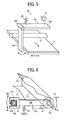
- Fig. 5 is a perspective view of a portion of the belt device 15 around the detecting unit 80.
- Fig. 6 is a perspective view of a portion of the belt device 15 around the correction roller 13 viewed from the back side of which.
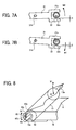
- Figs. 7A and 7B are schematic diagrams for explaining a movement of an oscillating arm 31 as a connecting member.
- Fig. 8 is a perspective view of a portion of the belt device 15 around the correction roller 13 viewed from the front side of which.
- Figs. 9A to 9C are schematic diagrams for explaining a movement of an adjusting member 60.
- the belt device 15 includes the intermediate transfer belt 8, the transfer rollers 9Y, 9M, 9C, and 9K, the drive roller 12A, the secondary-transfer roller 12B, the tension roller 12C, the correction roller 13, the movable roller 11, the regulating roller 14, the detecting unit 80, the photosensor 90, the belt cleaning unit 10, and error detecting sensors 88.
- the intermediate transfer belt 8 is arranged to be opposed to the photosensitive drums 1Y, 1M, 1C, and 1K.
- the intermediate transfer belt 8 is mainly supported by the five supporting rollers, i.e., the drive roller 12A, the secondary-transfer roller 12B, the tension roller 12C, the movable roller 11, and the correction roller 13.
- the intermediate transfer belt 8 the one made of a single-layered or multilayered resin, such as polyvinylidine difluoride (PVDF), ethylen etetrafluoroeyhylene copolymer (ETFE), poryimide (PI), and polycarbonate (PC), in which a conductive material such as carbon black is dispersed is employed.
- the intermediate transfer belt 8 is adjusted to have a volume resistivity in a range of 10 7 ⁇ cm to 10 12 ⁇ cm and a surface resistivity of a rear surface of which in a range of 10 8 ⁇ /sq to 10 12 ⁇ /sq.
- a thickness of the intermediate transfer belt 8 is preferably within a range of 80 micrometers ( ⁇ m) to 100 ⁇ m. In the present embodiment, the one having a thickness of 90 ⁇ m is employed as the intermediate transfer belt 8.
- the surface of the intermediate transfer belt 8 can be coated with a release layer made of fluorine contained resin such as, but not limited to, ETFE, polytetrafluoroethylene (PTFE), PVDF, perfluoro alkoxyl alkane (PFA), fluorinated ethylene propylene copolymer (FEP), and polyvinyl fluoride (PVF).
- fluorine contained resin such as, but not limited to, ETFE, polytetrafluoroethylene (PTFE), PVDF, perfluoro alkoxyl alkane (PFA), fluorinated ethylene propylene copolymer (FEP), and polyvinyl fluoride (PVF).
- the intermediate transfer belt 8 As a method for manufacturing the intermediate transfer belt 8, there are a cast molding method, a centrifugal molding method, and the like. The surface of the intermediate transfer belt 8 is polished if needed.
- the transfer rollers 9Y, 9M, 9C, and 9K are respectively opposed to the photosensitive drums 1Y, 1M, 1C, and 1K across the intermediate transfer belt 8.
- the movable roller 11 is supported by a supporting member (not shown) together with the transfer rollers 9Y, 9M, 9C, and 9K.
- the movable roller 11 is configured to cause the intermediate transfer belt 8 to come in contact with or move away from the photosensitive drums 1Y, 1M, 1C, and 1K.
- the intermediate transfer belt 8 is moved away from the photosensitive drums 1Y, 1M, 1C, and 1K as indicated by a dashed line in Fig. 3 .
- the reason why the intermediate transfer belt 8 is moved away from the photosensitive drums 1Y, 1M, 1C, and 1K is to reduce wear and deterioration of the intermediate transfer belt 8.
- the intermediate transfer belt 8 is moved away from the photosensitive drums 1Y, 1M, 1C, and 1K while no image is formed.
- the movable roller 11 moves downward together with the three transfer rollers 9Y, 9M, and 9C so that the intermediate transfer belt 8 is in contact with only the photosensitive drum 1K.
- the drive roller 12A is driven to rotate by a drive motor (not shown).
- the intermediate transfer belt 8 moves in a predetermined moving direction (in a clockwise direction in Fig. 3 ) in accordance with the rotation of the drive roller 12A.
- the secondary-transfer roller 12B is in contact with the secondary transfer roller 19 across the intermediate transfer belt 8.
- the tension roller 12C is in contact with an outer circumferential surface of the intermediate transfer belt 8.
- the belt cleaning unit 10 (a cleaning blade) is arranged between the secondary-transfer roller 12B and the tension roller 12C.
- the detecting unit 80 detects a displacement of the intermediate transfer belt 8 in the width direction (in a vertical direction with respect to a sheet face of Fig. 3 ).
- the detecting unit 80 includes an oscillating member 82, a displacement detecting sensor 81, and a spring 83.
- the oscillating member 82 is set to be in contact with an edge portion of the intermediate transfer belt 8 in the width direction.
- the displacement detecting sensor 81 detects an amount of displacement of the oscillating member 82.
- the spring 83 is attached to the oscillating member 82 to bias the oscillating member 82 in such a direction that the oscillating member 82 comes in contact with the intermediate transfer belt 8.
- the oscillating member 82 is composed of a first arm portion 82a, an oscillating spindle 82b, and a second arm portion 82c.
- One end of the first arm portion 82a is in contact with the edge portion of the intermediate transfer belt 8 in the width direction, and the other end is fixed to the oscillating spindle 82b.
- the oscillating spindle 82b is rotatably supported by an enclosure (not shown) of the belt device 15.
- One end of the second arm portion 82c is fixed to the oscillating spindle 82b.
- One end of the spring 83 is attached to the center of the second arm portion 82c, and the other end is attached to the enclosure.
- the oscillating member 82 oscillates (in a direction of a solid two-headed arrow shown in Fig. 5 ) along with a displacement of the intermediate transfer belt 8 in the width direction (in a direction of a dashed two-headed arrow shown in Fig. 5 ).
- the intermediate transfer belt 8 is set to move in the moving direction (in a direction of an arrow shown in Fig. 5 ) at a speed of 400 millimeters per second.
- the displacement detecting sensor 81 is fixed to the enclosure to be arranged above the other end of the second arm portion 82c.
- the displacement detecting sensor 81 includes a light-emitting element (an infrared light-emitting diode) and a position detecting element (a position sensitive detector (PSD)).
- the light-emitting element and the position detecting element are arranged in parallel in a horizontal direction with keeping a distance between them.
- An infrared light emitted from the light-emitting element is reflected on a surface of the second arm portion 82c, and the reflected light enters into the position detecting element.
- An incident position of the reflected light varies depending on a distance between the displacement detecting sensor 81 and the surface of the second arm portion 82c, and an output value of a light-receiving element (the displacement detecting sensor 81) also varies in proportion to the incident position. Therefore, an amount of displacement of the intermediate transfer belt 8 in the width direction (i.e., a distance between the displacement detecting sensor 81 and the surface of the second arm portion 82c) can be detected. Specifically, when a distance detected by the displacement detecting sensor 81 is smaller than a predetermined value, the intermediate transfer belt 8 is displaced on the right side in Fig. 5 from a target position. On the other hand, when a distance detected by the displacement detecting sensor 81 is larger than the predetermined value, the intermediate transfer belt 8 is displaced on the left side in Fig. 5 from the target position.
- the regulating roller 14 is arranged near the detecting unit 80.
- the regulating roller 14 regulates a displacement of the intermediate transfer belt 8 in a direction other than the width direction and the moving direction.
- the regulating roller 14 is arranged near a contact point where the oscillating member 82 (the first arm portion 82a) is in contact with the intermediate transfer belt 8 (on the upstream side of the contact point in the moving direction of the intermediate transfer belt 8).
- the regulating roller 14 increases the tension of the intermediate transfer belt 8 thereby regulating the displacement of the intermediate transfer belt 8 in the direction perpendicular to the width direction at the position of the detecting unit 80.
- the detecting unit 80 detects not only a displacement to be originally detected (i.e., a displacement in the width direction) but also a displacement in a different direction from the width direction and the moving direction.
- the detecting unit 80 can detect a bias of the intermediate transfer belt 8 at high accuracy.
- the correction roller 13 corrects the displacement of the intermediate transfer belt 8 in the width direction based on a result of the detection by the detecting unit 80. If the correction roller 13 fails to correct the meandering of the intermediate transfer belt 8 within a predetermined time (i.e., the result of the detection by the detecting unit 80 is not altered within the predetermined time), it is determined that a control error in meandering correction occurs, whereby the belt device 15 is caused to stop operation.
- the correction roller 13 is arranged on the upstream side of the photosensitive drums 1Y, 1M, 1C, and 1K in the moving direction of the intermediate transfer belt 8, and is in contact with an inner circumferential surface of the intermediate transfer belt 8. Furthermore, as shown in Figs. 4B and 6 , the correction roller 13 is configured to be capable of oscillating in directions X1 and X2 (in up and down directions) around an oscillating center W, which is fixedly-supported by a frame 70 via the adjusting member 60, in accordance with the oscillation of the oscillating arm 31 due to the rotation of a cam 32.
- the correction roller 13 oscillates in the direction X1 based on a result of the detection by the detecting unit 80 so as to correct the displacement (the meandering) of the intermediate transfer belt 8.
- the correction roller 13 oscillates in the direction X2 based on a result of the detection by the detecting unit 80 so as to correct the displacement (the meandering) of the intermediate transfer belt 8. Therefore, it is possible to prevent the intermediate transfer belt 8 from meandering, and also prevent the intermediate transfer belt 8 from being damaged, for example, by having contact with other components due to a significant displacement (bias) of which in the width direction.
- the detecting unit 80 and the regulating roller 14 are arranged to be away from the correction roller 13.
- the correction roller 13 is arranged on the upstream side of the photosensitive drums 1Y, 1M, 1C, and 1K in the moving direction of the intermediate transfer belt 8, while on the other hand, the detecting unit 80 and the regulating roller 14 are arranged on the downstream side of the photosensitive drums 1Y, 1M, 1C, and 1K in the moving direction of the intermediate transfer belt 8.
- the detection accuracy of the detecting unit 80 can be improved.
- the error detecting sensors 88 are provided at both sides of the intermediate transfer belt 8 with keeping a predetermined distance (about 5 millimeters) from the edge portions of the intermediate transfer belt 8 in the width direction, respectively.
- each of the error detecting sensors 88 includes an arm member and an optical sensor.
- the arm member has contact with the intermediate transfer belt 8 if the intermediate transfer belt 8 is significantly biased, and moves around an oscillating spindle along with the displacement of the intermediate transfer belt 8.
- the optical sensor optically senses the movement of the arm member.
- the error detecting sensors 88 detect an error, i.e., whether the intermediate transfer belt 8 is biased beyond a correctable range of displacement that can be corrected by the correction roller 13.
- an error is detected by the error detecting sensors 88, the drive roller 12A is forced to stop rotating so as to stop the movement of the intermediate transfer belt 8, and an error message "call a serviceman" (claiming for a service by a serviceman) is displayed on a display unit (not shown) of the printer 100.
- the photosensor 90 is arranged near the regulating roller 14.
- the photosensor 90 detects a position and a toner concentration of a toner image carried on the intermediate transfer belt 8. Specifically, after Y, M, C, and K toner images are transferred onto the intermediate transfer belt 8 as described above, the photosensor 90 optically detects a misalignment of each of the Y, M, C, and K toner images based on a patch pattern formed on the intermediate transfer belt 8. Based on a result of the misalignment detected by the photosensor 90, an exposure timing of each of laser lights L to be emitted from the exposure unit 7 to the photosensitive drums 1Y, 1M, 1C, and 1K is adjusted.
- the photosensor 90 optically detects a toner concentration of each of the Y, M, C, and K toner images based on a patch pattern formed on the intermediate transfer belt 8. Based on a result of the toner concentration detected by the photosensor 90, a concentration of each of Y, M, C, and K toners contained in developers in the developing units 5Y, 5M, 5C, and 5K is adjusted.
- the photosensor 90 is arranged near the regulating roller 14, so that the photosensor 90 can detect a position and a toner concentration of each of the toner images in a state where the deflection of the surface of the intermediate transfer belt 8 is reduced by the regulating roller 14. Therefore, a distance between the photosensor 90 and the toner images can be stabilized, so that it is possible to improve a detection accuracy of the photosensor 90, i.e., the photosensor 90 can detect a position and a toner concentration of each of the toner images at high accuracy.
- One end of the correction roller 13 (on the right side in Figs. 4A and 4B , i.e., the front side (the operating side) of the belt device 15) is fixed, and the other end (on the left side in Figs. 4A and 4B , i.e., the back side of the belt device 15) is configured to be movable in forward and backward directions (in the up and down directions).
- the meandering correcting mechanism causes the other end of the correction roller 13 to move in either the forward or backward direction to change the tilt of a rotating shaft of the correction roller 13, and thereby correcting a meandering of the intermediate transfer belt. As shown in Figs.
- the meandering correcting mechanism is composed of the correction roller 13 (one of the supporting rollers supporting the intermediate transfer belt 8), the oscillating arm 31, the cam 32, a tension spring 35, a drive motor (a stepping motor) 33, and a position detecting sensor 38.
- the oscillating arm 31 is made of a metal plate, and connected to a shaft portion 13b of the correction roller 13 (on the opposite side of the fixed end). Specifically, as shown in Fig. 6 , one end of the oscillating arm 31 is connected to the shaft portion 13b of the correction roller 13 via a bearing 34. A square U-shaped contact portion 31a is formed on the other end of the oscillating arm 31. The contact portion 31a holds the cam 32 in forward and backward directions M1 and M2. A center portion of the oscillating arm 31 (preferably on the side of the contact portion 31a) is rotatably supported by a side plate (not shown) of the belt device 15. The center portion of the oscillating arm 31 is referred to as an oscillating center 31b. Namely, the oscillating arm 31 oscillates around the oscillating center 31b.
- one end of the tension spring 35 as a biasing member is attached to the oscillating arm 31 at a position between the contact portion 31a and the oscillating center 31b.
- the other end of the tension spring 35 is attached to the enclosure of the belt device 15.
- the cam 32 is in contact with the contact portion 31a, and causes the oscillating arm 31 to move in either the forward or backward direction (in any of the directions M1 and M2 or any of the directions X1 and X2 shown in Fig. 6 ) due to the rotation of which to change the tilt of the rotating shaft of the correction roller 13 with respect to the moving direction thereby correcting the meandering of the intermediate transfer belt 8.
- an outer circumferential surface of the cam 32 which is in contact with the contact portion 31a, has a circular shape.
- the oscillating arm 31 is moved in either the forward direction or the backward direction.
- a shaft 32a of the cam 32 is arranged at an eccentric position, and connected to the stepping motor 33.
- the cam 32 is driven to rotate eccentrically around the shaft 32a by the stepping motor 33.
- the outer circumferential surface of the cam 32 is covered with a bearing 32b.
- the bearing 32b is a ball bearing, and balls are put into a space between the bearing 32b and a metal body of the cam 32.
- the ball bearing as the bearing 32b, a friction between the contact portion 31a and the cam 32 is reduced, so that it is possible to reduce wear and deterioration of both the oscillating arm 31 (the contact portion 31a) and the cam 32.
- a tiny gap ⁇ is provided between the contact portion 31a and the cam 32. Therefore, the cam 32 can be prevented from being nipped into the contact portion 31a.
- a detection plate 32c is installed on a portion of the outer circumferential surface of the cam 32, and the position detecting sensor 38 is arranged over the detection plate 32c in the belt device 15.
- the position detecting sensor 38 optically detects a position of the detection plate 32c, and thereby determining a posture of the cam 32 in the rotating direction so as to control a travel distance of the correction roller 13 in any of the directions X1 and X2.
- the adjusting member 60 is attached to a shaft portion 13a of the correction roller 13 on the side of the fixed end (the front side of the belt device 15).
- the adjusting member 60 adjusts a position of the fixed end of the correction roller 13.
- the shaft portion 13a (the fixed end) of the correction roller 13 is rotatably supported by the frame 70 of the belt device 15 via the adjusting member 60.
- the adjusting member 60 includes a circular cam 60a, a holding unit 60b, and a long hole 60c.
- the shaft portion 13a penetrates through the circular cam 60a.
- the shaft portion 13a is caused to rotate eccentrically.
- an outer circumferential surface of the circular cam 60a has a circular shape, and the circular cam 60a is engaged with a hole portion formed on the frame 70.
- a hole portion is formed on the circular cam 60a at an eccentric position with respect to the center of the circular cam 60a.
- the shaft portion 13a penetrates through the hole portion.
- the shaft portion 13a moves in the forward and backward directions (the up and down directions).
- the holding unit 60b is integrally molded with the circular cam 60a, and rotates along with the circular cam 60a.
- a worker grips and turns the holding unit 60b so as to turn the circular cam 60a thereby adjusting a position of the shaft portion 13a.
- a peripheral edge of the holding unit 60b is formed into a saw-tooth shape so that the worker can grip the holding unit 60b firmly.
- the long hole 60c has a shape of circular arc centered around the rotation center of the circular cam 60a.
- the long hole 60c serves as a posture retaining unit for retaining a posture of the circular cam 60a in the rotating direction.
- a screw 65 is screwed in a female screw portion of the frame 70 via the long hole 60c. Therefore, a position of the shaft portion 13a with respect to the frame 70 is determined without turning the circular cam 60a (the adjusting member 60).
- a default position of the correction roller 13 is significantly deviated in either the forward or backward direction away from a center position of a travel range of the correction roller 13, for example, because the supporting rollers 11, 12A to 12C, and 13 are installed in the belt device 15 in a state where the parallelism of the supporting rollers 11, 12A to 12C, and 13 is not sufficiently maintained, because the frame 70 that rotatably supports the supporting rollers 11, 12A to 12C, and 13 is distorted, or because the straightness of the supporting rollers 11, 12A to 12C, and 13 is not sufficiently maintained, the adjusting member 60 is manually operated so that the default position of the correction roller 13 comes to the center position of the travel range.
- Such a position adjustment is mostly performed by a worker in the last stage of an assembling process of the belt device 15 at a manufacturing facility.
- the belt device 15 is marketed, when the default position of the correction roller 13 is significantly deviated away from the center position of the travel range, for example, due to a distortion of the frame 70, the adjusting member 60 is operated by a serviceman.
- the belt device 15 can prevent occurrences of such conventional problems that the belt device 15 is caused stop operation because it is determined that a control error occurs when a meandering of the intermediate transfer belt 8 is not corrected within a predetermined time, and a meandering of the intermediate transfer belt 8 cannot be sufficiently corrected within the travel range of the correction roller 13.
- the adjusting member 60 is arranged on the operating side (i.e., the front side of the printer 100 where an openable cover is provided to be opened when the belt device 15 is attached to or removed from the printer 100). Therefore, it is possible to improve the operability when the adjusting member 60 is manually operated.
- the adjusting member 60 is designed to be relatively compact so as not to interfere with the intermediate transfer belt 8 when the intermediate transfer belt 8 is replaced.
- a trajectory of the shaft portion 13a that is moved in an arc by the adjusting member 60 is not coincident with a trajectory of the shaft portion 13b that is moved in an arc by the meandering correcting mechanism (the arc of the shaft portion 13a has a smaller diameter than that of the shaft portion 13b)
- both the shaft portions 13a and 13b are configured to move in the same direction, i.e., in the up or down direction enough to fulfill the function of the adjusting member 60.
- adjusting member 60 instead of the adjusting member 60, it is possible to use an adjusting unit capable of adjusting the position of the shaft portion 13a so that the trajectory of the shaft portion 13a is fully (or partially) coincident with the trajectory of the shaft portion 13b (in the directions X1 and X2) moved by the meandering correcting mechanism as viewed on a cross section perpendicular to the rotating shaft of the correction roller 13.
- the shaft portion 13a penetrates through a long hole 70a formed on the frame 70.
- the long hole 70a is formed so that a trajectory of the shaft portion 13a that is moved in an arc within a range of the long hole 70a (in directions Q1 and Q2) overlaps with a trajectory of the shaft portion 13b moved by the oscillating arm 31 (in the directions X1 and X2) as viewed on the cross section perpendicular to the rotating shaft of the correction roller 13.
- the default position of the correction roller 13 can be efficiently and reliably adjusted by the adjusting unit.
- a screw 68 is screwed in the female screw portion of the frame 70 via an arc-shaped long hole 67a formed on a holding member 67, which holds the shaft portion 13a and moves along with the shaft portion 13a, whereby the position of the shaft portion 13a in the turning direction is determined.
- the belt device 15 is configured to be capable of adjusting a position of the fixed end of the correction roller 13 for correcting a meandering of the intermediate transfer belt 8. Therefore, even when the supporting rollers 11, 12A to 12C, and 13 supporting the intermediate transfer belt 8 are installed in the belt device 15 in a state where the parallelism of the supporting rollers 11, 12A to 12C, and 13 is not sufficiently maintained, the frame that rotatably supports the supporting rollers 11, 12A to 12C, and 13 is distorted, or the straightness of the supporting rollers 11, 12A to 12C, and 13 is not sufficiently maintained, a meandering of the intermediate transfer belt 8 can be reliably corrected with a relatively simple configuration.
- the present invention is applied to the belt device 15 including the intermediate transfer belt 8 as a belt member.
- the present invention is not limited to the embodiment.
- the present invention can be applied to a belt device including a conveying belt as a belt member (in this belt device, a plurality of toner images in different colors is transferred onto a recording medium conveyed on the conveying belt) or a belt device including a photosensitive element belt (i.e., an endless-belt type of a photosensitive element that performs the same function as the photosensitive drums in the present embodiment) as a belt member.
- a photosensitive element belt i.e., an endless-belt type of a photosensitive element that performs the same function as the photosensitive drums in the present embodiment
- it is just configured so as to adjust a position of a fixed end of a roller member for correcting a meandering of the belt member, whereby it is possible to achieve the same effect as the belt device 15 according to the embodiment.
- the adjusting member 60 is configured to be manually operated. Alternatively, it is also possible to configure the adjusting member 60 to be automatically operated. Furthermore, a gear portion can be provided on the peripheral edge of the holding unit 60b of the adjusting member 60. In this case, a gear engaged with the gear portion is configured to be driven to rotate in the forward or backward direction by a stepping motor.
- a belt device is configured to be capable of adjusting a position of a fixed end of a roller member for correcting a meandering of a belt member. Therefore, even when a plurality of supporting rollers supporting the belt member is installed in the belt device in a state where the parallelism of the supporting rollers is not sufficiently maintained, a frame that rotatably supports the supporting rollers is distorted, or the straightness of the supporting rollers is not sufficiently maintained, a meandering of the belt member can be reliably corrected with a relatively simple configuration.
Landscapes
- Physics & Mathematics (AREA)
- General Physics & Mathematics (AREA)
- Electrostatic Charge, Transfer And Separation In Electrography (AREA)
Abstract
Description
- The present application claims priority to and incorporates by reference the entire contents of Japanese priority document
2007-324929 - The present invention relates to a belt device capable of correcting a meandering of a belt, such as an intermediate transfer belt, a conveying belt, or a photosensitive element belt, and an image forming apparatus including the belt device.
- Among image forming apparatuses, such as a copier, a printer, a facsimile machine, and a multifunction product (MFP), a tandem-type color image forming apparatus including an intermediate transfer belt (for example, as disclosed in Japanese Patent Application Laid-open No.
2006-343629 2001-38340 - In such a tandem-type color image forming apparatus, four photosensitive drums as image carriers are tandemly arranged to be opposed to an intermediate transfer belt. The image forming apparatus forms a full-color image in such a manner that black (K), yellow (Y), magenta (M), and cyan (C) toner images are formed on the photosensitive drums, respectively. The K, Y, M, and C toner images formed on the photosensitive drums are sequentially transferred onto the intermediate transfer belt in a superimposed manner. The superimposed toner image transferred onto the intermediate transfer belt is further transferred onto a recording medium, and thereby forming a full-color image.
- Various technologies have developed to improve such an image forming apparatus. For example, an image forming apparatus as disclosed in Japanese Patent Application Laid-open No.
2006-343629 2001-38340 - Specifically, in the image forming apparatus disclosed in Japanese Patent Application Laid-open No.
2006-343629 - Furthermore, in a belt device disclosed in Japanese Patent No.
3082452 - Moreover, in a belt device disclosed in Japanese Patent Application Laid-open No.
H10-152242 - However, the above conventional technologies have problems. For example, in the image forming apparatus disclosed in Japanese Patent Application Laid-open No.
2006-343629 - To solve the problems, an assembly accuracy of components of the belt device, such as the roller members and the frame, and an accuracy of each of the components need to be improved. However, in this case, there is a production limitation costwise.
- These problems are especially prominent in a case where the apparatus is large in size because a length of the roller members in a direction of the rotating shaft gets longer.
- Incidentally, the above problems are not limited to a belt device employing an intermediate transfer belt as a belt member, but are common issues among belt devices that correct a meandering of a belt member regardless of a type of the belt member.
- It is an object of the present invention to at least partially solve the problems in the conventional technology.
- According to one aspect of the present invention, there is provided a belt device including a belt member that is supported by a plurality of rollers and moves in a predetermined moving direction; a detecting unit that detects a displacement of the belt member in its width direction; a correcting unit that moves a second end of a first roller from among the rollers in either one of a forward direction and a backward direction while fixing its first end based on a result of detecting the displacement of the belt member such that a tilt of a rotating shaft of the first roller is changed to correct a meandering of the belt member; and an adjusting unit that adjusts a fixing position of the first end.
- The above and other objects, features, advantages and technical and industrial significance of this invention will be better understood by reading the following detailed description of presently preferred embodiments of the invention, when considered in connection with the accompanying drawings.
-
-
Fig. 1 is a side view of an image forming apparatus including a belt device according to an embodiment of the present invention; -
Fig. 2 is an enlarged view of a process unit of the image forming apparatus; -
Fig. 3 is a configuration diagram of the belt device; -
Figs. 4A and 4B are respectively a top view and a side view of a portion of the belt device viewed in a width direction of an intermediate transfer belt; -
Fig. 5 is a perspective view of a portion of the belt device around a detecting unit; -
Fig. 6 is a perspective view of a portion of the belt device around a correction roller viewed from a back side of which; -
Figs. 7A and 7B are schematic diagrams for explaining a movement of a connecting member; -
Fig. 8 is a perspective view of a portion of the belt device around the correction roller viewed from a front side of which; -
Figs. 9A to 9C are schematic diagrams for explaining a movement of an adjusting member shown inFig. 8 ; and -
Fig. 10 is a perspective view of the portion of the belt device including an adjusting member as a modified example of that is shown inFig. 8 . - Exemplary embodiments of the present invention are explained in detail below with reference to the accompanying drawings.
- First, a configuration and an operational behavior of an image forming apparatus including a belt device according to an embodiment of the present invention are explained below with reference to
Figs. 1 and 2 . -
Fig. 1 is a side view of aprinter 100 as the image forming apparatus according to the embodiment of the present invention. - As shown in
Fig. 1 , theprinter 100 includes abelt device 15,process units exposure unit 7, asecondary transfer roller 19, asheet feed unit 26, asheet feed roller 27, a pair ofregistration rollers 28, and afixing unit 20. Thebelt device 15 is arranged in the center of a main body of theprinter 100. Thebelt device 15 includes anintermediate transfer belt 8. Theprocess units intermediate transfer belt 8, and respectively form yellow (Y), magenta (M), cyan (C), and black (K) toner images. Theexposure unit 7 is arranged above theprocess units - The
process units process unit 6Y is explained as an example of all the process units, and the description of theprocess units -
Fig. 2 is an enlarged view of theprocess unit 6Y. As shown inFig. 2 , theprocess unit 6Y includes aphotosensitive drum 1Y as an image carrier, acharging unit 4Y, a developingunit 5Y, acleaning unit 2Y, and a neutralizing unit (not shown). Thecharging unit 4Y, the developingunit 5Y, thecleaning unit 2Y, and the neutralizing unit are arranged around thephotosensitive drum 1Y. Incidentally, each of theprocess units process unit 6Y, and elements included in each of theprocess units process unit 6Y with suffix of "M", "C", and "K". - A process of forming a Y-toner image on the
photosensitive drum 1Y performed by theprocess unit 6Y is explained below with reference toFig. 2 . - The
photosensitive drum 1Y is driven to rotate in a counterclockwise direction by a drive motor (not shown). At a position opposed to thecharging unit 4Y, a surface of thephotosensitive drum 1Y is uniformly charged by thecharging unit 4Y. - After that, when the charged portion of the surface of the
photosensitive drum 1Y comes to an exposure position due to the rotation of thephotosensitive drum 1Y, the surface of thephotosensitive drum 1Y is exposed to a laser light L emitted from theexposure unit 7, whereby an electrostatic latent image corresponding to Y image data is formed on the surface of thephotosensitive drum 1Y. - When the portion of the surface of the
photosensitive drum 1Y where the electrostatic latent image is formed comes to a position opposed to the developingunit 5Y, the electrostatic latent image is developed into a Y-toner image by the developingunit 5Y. - When the portion of the surface of the
photosensitive drum 1Y where the Y-toner image is formed comes to a position opposed to atransfer roller 9Y across theintermediate transfer belt 8, the Y-toner image formed on thephotosensitive drum 1Y is primary-transferred onto theintermediate transfer belt 8. At this time, a residual toner remains on the surface of thephotosensitive drum 1Y. - When the portion of the surface of the
photosensitive drum 1Y where the residual toner remains comes to a position opposed to thecleaning unit 2Y, the residual toner is removed from the surface of thephotosensitive drum 1Y by acleaning blade 2a, and collected in thecleaning unit 2Y. - After that, when the portion of the surface of the
photosensitive drum 1Y comes to a position opposed to the neutralizing unit, a residual potential remaining on the surface of thephotosensitive drum 1Y is removed by the neutralizing unit. - In this manner, the process of forming the Y-toner image on the
photosensitive drum 1Y is complete. - The above process is performed by each of the
process units process unit 6Y. Specifically, a light source of theexposure unit 7 emits laser lights L corresponding to M, C, and K image data towardphotosensitive drums - After electrostatic latent images formed on the
photosensitive drums intermediate transfer belt 8 in a superimposed manner, and thereby forming a full-color toner image on theintermediate transfer belt 8. - Subsequently, a process of transferring the full-color toner image onto the
intermediate transfer belt 8 is explained below with reference toFig. 3 . As shown inFig. 3 , thebelt device 15 includes theintermediate transfer belt 8, the fourtransfer rollers drive roller 12A, a secondary-transfer roller 12B, atension roller 12C, acorrection roller 13, amovable roller 11, a regulatingroller 14, a detectingunit 80, aphotosensor 90, and abelt cleaning unit 10. Theintermediate transfer belt 8 is supported by themovable roller 11, thedrive roller 12A, the secondary-transfer roller 12B, thetension roller 12C, and the correction roller 13 (hereinafter, "the supportingrollers intermediate transfer belt 8 moves endlessly in a direction of an arrow shown inFig. 3 in accordance with the rotation of thedrive roller 12A. - The
transfer rollers photosensitive drums intermediate transfer belt 8. Primary-transfer nip portions are formed between thephotosensitive drums transfer rollers transfer rollers - The
intermediate transfer belt 8 moves in the direction of the arrow, and sequentially passes through the primary-transfer nip portions. As a result, the Y, M, C, and K toner images formed on thephotosensitive drums intermediate transfer belt 8 in a superimposed manner. - The secondary-
transfer roller 12B is arranged to be opposed to thesecondary transfer roller 19 across theintermediate transfer belt 8. A secondary-transfer nip portion is formed between the secondary-transfer roller 12B and thesecondary transfer roller 19. When theintermediate transfer belt 8 onto which the superimposed full-color toner image is primary-transferred passes through the secondary-transfer nip portion, the full-color toner image is secondary-transferred onto a recording medium P conveyed to the secondary-transfer nip portion. At this time, a residual toner remains on theintermediate transfer belt 8. - When the
intermediate transfer belt 8 comes to a position opposed to thebelt cleaning unit 10, the residual toner is removed from theintermediate transfer belt 8 by thebelt cleaning unit 10. - In this manner, the process of transferring the full-color toner image onto the
intermediate transfer belt 8 is complete. Incidentally, a configuration and an operational behavior of thebelt device 15 will be explained in detail later with reference toFigs. 3 to 9 . - How the recording medium P is conveyed to the secondary-transfer nip portion is explained with reference to
Fig. 1 . A recording medium P is fed from thesheet feed unit 26 arranged on the lower part of the main body of the printer 100 (or a sheet feed unit arranged on the side part of the main body), and conveyed to the secondary-transfer nip portion via thesheet feed roller 27 and theregistration rollers 28. - Specifically, a stack of recording media P, such as transfer sheets, is contained in the
sheet feed unit 26. When thesheet feed roller 27 is driven to rotate in the counterclockwise direction inFig. 1 , a top recording medium P of the stack is picked up and fed toward theregistration rollers 28. - The recording medium P conveyed to the
registration rollers 28 is temporarily stopped at a nip portion formed between theregistration rollers 28 that are not driven to rotate, i.e., stop rotating at this time. In synchronization with a timing of the full-color toner image on theintermediate transfer belt 8, theregistration rollers 28 are driven to rotate, and the recording medium P is conveyed to the secondary-transfer nip portion through theregistration rollers 28. By passing through the secondary-transfer nip portion, the full-color toner image is transferred onto the recording medium P. - After that, the recording medium P on which the full-color toner image is transferred is conveyed to the fixing
unit 20. In the fixingunit 20, the full-color toner image is fixed on the recording medium P by the application of heat and pressure by a fixing roller and a pressure roller, and thereby forming a full-color image on the recording medium P. - Then, the recording medium P is discharged from the
printer 100 by a pair of discharge rollers (not shown), and stacked on a stack unit. - In this manner, a series of processes for forming the full-color image performed by the
printer 100 is complete. - Subsequently, a configuration and an operational behavior of the developing unit 5 are explained in detail below by taking the developing
unit 5Y of theprocess unit 6Y as an example. - As shown in
Fig. 2 , the developingunit 5Y includes a developingroller 51Y, adoctor blade 52Y, two conveyingscrews 55Y, atoner replenishing path 43Y, and a toner-concentration detecting sensor 56Y. The developingroller 51Y is arranged to be opposed to thephotosensitive drum 1Y. The developingroller 51Y is composed of a magnet and a sleeve. The magnet is fixedly-mounted inside the developingroller 51Y, and covered with the sleeve. The sleeve is capable of rotating around the magnet. Thedoctor blade 52Y is arranged to be opposed to the developingroller 51Y. The conveying screws 55Y are provided in a developer containing unit. The developer containing unit is separated into two separate areas, and the conveyingscrews 55Y are respectively arranged in the separate areas. The developer containing unit contains a two-component developer composed of a carrier and a toner. Thetoner replenishing path 43Y is communicated with the developer containing unit via an opening formed on the developer containing unit. The toner-concentration detecting sensor 56Y detects a concentration of the toner contained in the developer. - The sleeve of the developing
roller 51Y rotates in a direction of an arrow shown inFig. 2 . The developer is carried on the developingroller 51Y by the action of a magnetic field generated by the magnet. The developer moves over the surface of the developingroller 51Y in accordance with the rotation of the sleeve. The developer is adjusted so that a ratio (a concentration) of the toner in the developer falls within a predetermined range. - When a toner is replenished into the developer containing unit (see a dashed arrow shown in
Fig. 2 ), the toner is circulated through the two separate areas of the developer containing unit while being agitated by the conveyingscrews 55Y so as to be mixed with the developer. The toner in the developer is adhered to the carrier due to an electrostatic charge caused by a friction with the carrier, and carried on the developingroller 51Y together with the carrier by the action of a magnetic force generated on the developingroller 51Y. - The developer carried on the developing
roller 51Y is conveyed in the direction of the arrow shown inFig. 2 . At a position opposed to thedoctor blade 52Y, an excessive amount of the developer on the developingroller 51Y is scraped off to an appropriate amount by thedoctor blade 52Y so as to uniform the developer on the developingroller 51Y, and conveyed to a position opposed to thephotosensitive drum 1Y (a developing area). The toner is adhered to the latent image formed on thephotosensitive drum 1Y by an electrostatic charge generated in the developing area. When the developer remaining on the developingroller 51Y comes to the upper side of the developer containing unit in accordance with the rotation of the sleeve, the developer is come off from the developingroller 51Y. - Subsequently, the configuration and the operational behavior of the
belt device 15 according to the present embodiment are explained in detail below with reference toFigs. 3 to 9 . -
Fig. 3 is a configuration diagram of thebelt device 15.Fig. 4A is a top view of a portion of thebelt device 15 viewed in a width direction of theintermediate transfer belt 8.Fig. 4B is a side view of the portion of thebelt device 15 shown inFig. 4A .Fig. 5 is a perspective view of a portion of thebelt device 15 around the detectingunit 80.Fig. 6 is a perspective view of a portion of thebelt device 15 around thecorrection roller 13 viewed from the back side of which.Figs. 7A and 7B are schematic diagrams for explaining a movement of anoscillating arm 31 as a connecting member.Fig. 8 is a perspective view of a portion of thebelt device 15 around thecorrection roller 13 viewed from the front side of which.Figs. 9A to 9C are schematic diagrams for explaining a movement of an adjustingmember 60. - As shown in
Figs. 3, 4A, and 4B , thebelt device 15 includes theintermediate transfer belt 8, thetransfer rollers drive roller 12A, the secondary-transfer roller 12B, thetension roller 12C, thecorrection roller 13, themovable roller 11, the regulatingroller 14, the detectingunit 80, thephotosensor 90, thebelt cleaning unit 10, anderror detecting sensors 88. - The
intermediate transfer belt 8 is arranged to be opposed to thephotosensitive drums intermediate transfer belt 8 is mainly supported by the five supporting rollers, i.e., thedrive roller 12A, the secondary-transfer roller 12B, thetension roller 12C, themovable roller 11, and thecorrection roller 13. - In the present embodiment, as the
intermediate transfer belt 8, the one made of a single-layered or multilayered resin, such as polyvinylidine difluoride (PVDF), ethylen etetrafluoroeyhylene copolymer (ETFE), poryimide (PI), and polycarbonate (PC), in which a conductive material such as carbon black is dispersed is employed. Theintermediate transfer belt 8 is adjusted to have a volume resistivity in a range of 107 Ω·cm to 1012 Ω·cm and a surface resistivity of a rear surface of which in a range of 108 Ω/sq to 1012 Ω/sq. Furthermore, a thickness of theintermediate transfer belt 8 is preferably within a range of 80 micrometers (µm) to 100 µm. In the present embodiment, the one having a thickness of 90 µm is employed as theintermediate transfer belt 8. - If needed, the surface of the
intermediate transfer belt 8 can be coated with a release layer made of fluorine contained resin such as, but not limited to, ETFE, polytetrafluoroethylene (PTFE), PVDF, perfluoro alkoxyl alkane (PFA), fluorinated ethylene propylene copolymer (FEP), and polyvinyl fluoride (PVF). - As a method for manufacturing the
intermediate transfer belt 8, there are a cast molding method, a centrifugal molding method, and the like. The surface of theintermediate transfer belt 8 is polished if needed. - The
transfer rollers photosensitive drums intermediate transfer belt 8. - The
movable roller 11 is supported by a supporting member (not shown) together with thetransfer rollers movable roller 11 is configured to cause theintermediate transfer belt 8 to come in contact with or move away from thephotosensitive drums - Specifically, when the
movable roller 11 moves downward together with thetransfer rollers intermediate transfer belt 8 is moved away from thephotosensitive drums Fig. 3 . The reason why theintermediate transfer belt 8 is moved away from thephotosensitive drums intermediate transfer belt 8. Theintermediate transfer belt 8 is moved away from thephotosensitive drums movable roller 11 moves downward together with the threetransfer rollers intermediate transfer belt 8 is in contact with only thephotosensitive drum 1K. - The
drive roller 12A is driven to rotate by a drive motor (not shown). Theintermediate transfer belt 8 moves in a predetermined moving direction (in a clockwise direction inFig. 3 ) in accordance with the rotation of thedrive roller 12A. - The secondary-
transfer roller 12B is in contact with thesecondary transfer roller 19 across theintermediate transfer belt 8. Thetension roller 12C is in contact with an outer circumferential surface of theintermediate transfer belt 8. The belt cleaning unit 10 (a cleaning blade) is arranged between the secondary-transfer roller 12B and thetension roller 12C. - The detecting
unit 80 detects a displacement of theintermediate transfer belt 8 in the width direction (in a vertical direction with respect to a sheet face ofFig. 3 ). - Specifically, as shown in
Fig. 5 , the detectingunit 80 includes an oscillatingmember 82, adisplacement detecting sensor 81, and aspring 83. The oscillatingmember 82 is set to be in contact with an edge portion of theintermediate transfer belt 8 in the width direction. Thedisplacement detecting sensor 81 detects an amount of displacement of the oscillatingmember 82. Thespring 83 is attached to the oscillatingmember 82 to bias the oscillatingmember 82 in such a direction that the oscillatingmember 82 comes in contact with theintermediate transfer belt 8. - The oscillating
member 82 is composed of afirst arm portion 82a, anoscillating spindle 82b, and asecond arm portion 82c. One end of thefirst arm portion 82a is in contact with the edge portion of theintermediate transfer belt 8 in the width direction, and the other end is fixed to theoscillating spindle 82b. Theoscillating spindle 82b is rotatably supported by an enclosure (not shown) of thebelt device 15. One end of thesecond arm portion 82c is fixed to theoscillating spindle 82b. One end of thespring 83 is attached to the center of thesecond arm portion 82c, and the other end is attached to the enclosure. - The oscillating
member 82 oscillates (in a direction of a solid two-headed arrow shown inFig. 5 ) along with a displacement of theintermediate transfer belt 8 in the width direction (in a direction of a dashed two-headed arrow shown inFig. 5 ). Incidentally, in the present embodiment, theintermediate transfer belt 8 is set to move in the moving direction (in a direction of an arrow shown inFig. 5 ) at a speed of 400 millimeters per second. - The
displacement detecting sensor 81 is fixed to the enclosure to be arranged above the other end of thesecond arm portion 82c. Thedisplacement detecting sensor 81 includes a light-emitting element (an infrared light-emitting diode) and a position detecting element (a position sensitive detector (PSD)). The light-emitting element and the position detecting element are arranged in parallel in a horizontal direction with keeping a distance between them. An infrared light emitted from the light-emitting element is reflected on a surface of thesecond arm portion 82c, and the reflected light enters into the position detecting element. An incident position of the reflected light varies depending on a distance between thedisplacement detecting sensor 81 and the surface of thesecond arm portion 82c, and an output value of a light-receiving element (the displacement detecting sensor 81) also varies in proportion to the incident position. Therefore, an amount of displacement of theintermediate transfer belt 8 in the width direction (i.e., a distance between thedisplacement detecting sensor 81 and the surface of thesecond arm portion 82c) can be detected. Specifically, when a distance detected by thedisplacement detecting sensor 81 is smaller than a predetermined value, theintermediate transfer belt 8 is displaced on the right side inFig. 5 from a target position. On the other hand, when a distance detected by thedisplacement detecting sensor 81 is larger than the predetermined value, theintermediate transfer belt 8 is displaced on the left side inFig. 5 from the target position. - The regulating
roller 14 is arranged near the detectingunit 80. The regulatingroller 14 regulates a displacement of theintermediate transfer belt 8 in a direction other than the width direction and the moving direction. Specifically, the regulatingroller 14 is arranged near a contact point where the oscillating member 82 (thefirst arm portion 82a) is in contact with the intermediate transfer belt 8 (on the upstream side of the contact point in the moving direction of the intermediate transfer belt 8). - By such a configuration, it is possible to reduce a displacement (a deflection) of the
intermediate transfer belt 8 in a direction perpendicular to the width direction (in a vertical direction with respect to a sheet face ofFig. 4A ) at a position of the detecting unit 80 (at the contact point between the oscillatingmember 82 and the intermediate transfer belt 8). In other words, the regulatingroller 14 increases the tension of theintermediate transfer belt 8 thereby regulating the displacement of theintermediate transfer belt 8 in the direction perpendicular to the width direction at the position of the detectingunit 80. Therefore, it is possible to reduce such a disadvantageous possibility that the detectingunit 80 detects not only a displacement to be originally detected (i.e., a displacement in the width direction) but also a displacement in a different direction from the width direction and the moving direction. Thus, it is possible to improve a detection accuracy of the detectingunit 80, i.e., the detectingunit 80 can detect a bias of theintermediate transfer belt 8 at high accuracy. - When the detecting
unit 80 detects a displacement (an amount of displacement) of theintermediate transfer belt 8, thecorrection roller 13 corrects the displacement of theintermediate transfer belt 8 in the width direction based on a result of the detection by the detectingunit 80. If thecorrection roller 13 fails to correct the meandering of theintermediate transfer belt 8 within a predetermined time (i.e., the result of the detection by the detectingunit 80 is not altered within the predetermined time), it is determined that a control error in meandering correction occurs, whereby thebelt device 15 is caused to stop operation. - As shown in
Fig. 3 , thecorrection roller 13 is arranged on the upstream side of thephotosensitive drums intermediate transfer belt 8, and is in contact with an inner circumferential surface of theintermediate transfer belt 8. Furthermore, as shown inFigs. 4B and6 , thecorrection roller 13 is configured to be capable of oscillating in directions X1 and X2 (in up and down directions) around an oscillating center W, which is fixedly-supported by aframe 70 via the adjustingmember 60, in accordance with the oscillation of theoscillating arm 31 due to the rotation of acam 32. - When the
intermediate transfer belt 8 is displaced (biased) on the right side inFig. 4A , thecorrection roller 13 oscillates in the direction X1 based on a result of the detection by the detectingunit 80 so as to correct the displacement (the meandering) of theintermediate transfer belt 8. On the other hand, when theintermediate transfer belt 8 is displaced on the left side inFig. 4A , thecorrection roller 13 oscillates in the direction X2 based on a result of the detection by the detectingunit 80 so as to correct the displacement (the meandering) of theintermediate transfer belt 8. Therefore, it is possible to prevent theintermediate transfer belt 8 from meandering, and also prevent theintermediate transfer belt 8 from being damaged, for example, by having contact with other components due to a significant displacement (bias) of which in the width direction. - Incidentally, a configuration and an operational behavior of the correcting roller 13 (a meandering correcting mechanism) will be explained in detail later with reference to
Figs. 6 ,7A, and 7B . - In the present embodiment, the detecting
unit 80 and the regulatingroller 14 are arranged to be away from thecorrection roller 13. Specifically, thecorrection roller 13 is arranged on the upstream side of thephotosensitive drums intermediate transfer belt 8, while on the other hand, the detectingunit 80 and the regulatingroller 14 are arranged on the downstream side of thephotosensitive drums intermediate transfer belt 8. - By arranging the detecting
unit 80 and the regulatingroller 14 to be away from thecorrection roller 13, there is no decrease in a regulating force exerted on theintermediate transfer belt 8 by the regulating roller 14 (a force restraining theintermediate transfer belt 8 from being displaced in the perpendicular direction) even when thecorrection roller 13 oscillates to correct the displacement. Therefore, the detection accuracy of the detectingunit 80 can be improved. - In the
belt device 15, as shown inFig. 4A , theerror detecting sensors 88 are provided at both sides of theintermediate transfer belt 8 with keeping a predetermined distance (about 5 millimeters) from the edge portions of theintermediate transfer belt 8 in the width direction, respectively. - Although it is not illustrated in the drawing, each of the
error detecting sensors 88 includes an arm member and an optical sensor. The arm member has contact with theintermediate transfer belt 8 if theintermediate transfer belt 8 is significantly biased, and moves around an oscillating spindle along with the displacement of theintermediate transfer belt 8. The optical sensor optically senses the movement of the arm member. - The
error detecting sensors 88 detect an error, i.e., whether theintermediate transfer belt 8 is biased beyond a correctable range of displacement that can be corrected by thecorrection roller 13. When an error is detected by theerror detecting sensors 88, thedrive roller 12A is forced to stop rotating so as to stop the movement of theintermediate transfer belt 8, and an error message "call a serviceman" (claiming for a service by a serviceman) is displayed on a display unit (not shown) of theprinter 100. - Furthermore, in the
belt device 15, as shown inFigs. 3 and 4A , thephotosensor 90 is arranged near the regulatingroller 14. Thephotosensor 90 detects a position and a toner concentration of a toner image carried on theintermediate transfer belt 8. Specifically, after Y, M, C, and K toner images are transferred onto theintermediate transfer belt 8 as described above, the photosensor 90 optically detects a misalignment of each of the Y, M, C, and K toner images based on a patch pattern formed on theintermediate transfer belt 8. Based on a result of the misalignment detected by thephotosensor 90, an exposure timing of each of laser lights L to be emitted from theexposure unit 7 to thephotosensitive drums intermediate transfer belt 8. Based on a result of the toner concentration detected by thephotosensor 90, a concentration of each of Y, M, C, and K toners contained in developers in the developingunits 5Y, 5M, 5C, and 5K is adjusted. - In this manner, the
photosensor 90 is arranged near the regulatingroller 14, so that the photosensor 90 can detect a position and a toner concentration of each of the toner images in a state where the deflection of the surface of theintermediate transfer belt 8 is reduced by the regulatingroller 14. Therefore, a distance between the photosensor 90 and the toner images can be stabilized, so that it is possible to improve a detection accuracy of thephotosensor 90, i.e., the photosensor 90 can detect a position and a toner concentration of each of the toner images at high accuracy. - Subsequently, the configuration and the operational behavior of the correction roller 13 (the meandering correcting mechanism) is explained in detail below.
- One end of the correction roller 13 (on the right side in
Figs. 4A and 4B , i.e., the front side (the operating side) of the belt device 15) is fixed, and the other end (on the left side inFigs. 4A and 4B , i.e., the back side of the belt device 15) is configured to be movable in forward and backward directions (in the up and down directions). The meandering correcting mechanism causes the other end of thecorrection roller 13 to move in either the forward or backward direction to change the tilt of a rotating shaft of thecorrection roller 13, and thereby correcting a meandering of the intermediate transfer belt. As shown inFigs. 4A, 4B , and6 , the meandering correcting mechanism is composed of the correction roller 13 (one of the supporting rollers supporting the intermediate transfer belt 8), theoscillating arm 31, thecam 32, atension spring 35, a drive motor (a stepping motor) 33, and aposition detecting sensor 38. - The
oscillating arm 31 is made of a metal plate, and connected to ashaft portion 13b of the correction roller 13 (on the opposite side of the fixed end). Specifically, as shown inFig. 6 , one end of theoscillating arm 31 is connected to theshaft portion 13b of thecorrection roller 13 via abearing 34. A squareU-shaped contact portion 31a is formed on the other end of theoscillating arm 31. Thecontact portion 31a holds thecam 32 in forward and backward directions M1 and M2. A center portion of the oscillating arm 31 (preferably on the side of thecontact portion 31a) is rotatably supported by a side plate (not shown) of thebelt device 15. The center portion of theoscillating arm 31 is referred to as anoscillating center 31b. Namely, theoscillating arm 31 oscillates around theoscillating center 31b. - In the present embodiment, one end of the
tension spring 35 as a biasing member is attached to theoscillating arm 31 at a position between thecontact portion 31a and theoscillating center 31b. The other end of thetension spring 35 is attached to the enclosure of thebelt device 15. By the action of thetension spring 35, theoscillating arm 31 is biased so that thecontact portion 31a is reliably in contact with thecam 32. - The
cam 32 is in contact with thecontact portion 31a, and causes theoscillating arm 31 to move in either the forward or backward direction (in any of the directions M1 and M2 or any of the directions X1 and X2 shown inFig. 6 ) due to the rotation of which to change the tilt of the rotating shaft of thecorrection roller 13 with respect to the moving direction thereby correcting the meandering of theintermediate transfer belt 8. - Specifically, an outer circumferential surface of the
cam 32, which is in contact with thecontact portion 31a, has a circular shape. By eccentric rotation of thecam 32, theoscillating arm 31 is moved in either the forward direction or the backward direction. More specifically, ashaft 32a of thecam 32 is arranged at an eccentric position, and connected to the steppingmotor 33. Thecam 32 is driven to rotate eccentrically around theshaft 32a by the steppingmotor 33. - Incidentally, the outer circumferential surface of the
cam 32 is covered with abearing 32b. Specifically, thebearing 32b is a ball bearing, and balls are put into a space between the bearing 32b and a metal body of thecam 32. By the use of the ball bearing as thebearing 32b, a friction between thecontact portion 31a and thecam 32 is reduced, so that it is possible to reduce wear and deterioration of both the oscillating arm 31 (thecontact portion 31a) and thecam 32. - The operational behavior of the meandering correcting mechanism is explained in detail below with reference to
Figs. 7A and 7B . - As shown in
Fig. 7A , when theshaft 32a is located lower than the center of thecam 32 due to the rotation of thecam 32, thecam 32 is in contact with a top inner surface of thecontact portion 31a, so that thecontact portion 31a is pushed up in the direction M2 (the forward direction). As a result, thecorrection roller 13 is moved in the direction X2 shown inFig. 6 around the oscillating center W. - On the other hand, as shown in
Fig. 7B , when theshaft 32a is located higher than the center of thecam 32 due to the rotation of thecam 32, thecontact portion 31a is pushed down in the direction M1 (the backward direction) by a bias force of thetension spring 35 in a state where thecam 32 is in contact with the top inner surface of thecontact portion 31a. As a result, thecorrection roller 13 is moved in the direction X1 shown inFig. 6 around the oscillating center W. - As shown in
Figs. 7A and 7B , a tiny gap δ is provided between thecontact portion 31a and thecam 32. Therefore, thecam 32 can be prevented from being nipped into thecontact portion 31a. - Furthermore, as shown in
Fig. 4A , adetection plate 32c is installed on a portion of the outer circumferential surface of thecam 32, and theposition detecting sensor 38 is arranged over thedetection plate 32c in thebelt device 15. Theposition detecting sensor 38 optically detects a position of thedetection plate 32c, and thereby determining a posture of thecam 32 in the rotating direction so as to control a travel distance of thecorrection roller 13 in any of the directions X1 and X2. - In the present embodiment, regardless of the bias force of the
tension spring 35, when theshaft 32a is located higher than the center of thecam 32 in a state where thecam 32 is nipped into a bottom inner surface of thecontact portion 31a due to the rotation of thecam 32, thecontact portion 31a is pushed down in the direction M1 (the backward direction) in a state where thecam 32 is in contact with the bottom inner surface of thecontact portion 31a. As a result, thecorrection roller 13 is moved in the direction X1 shown inFig. 6 around the oscillating center W. - Subsequently, a configuration and an operational behavior of the adjusting
member 60 as one of characteristic features of thebelt device 15 according to the present embodiment is explained in detail below with reference toFigs. 8 and9A to 9C . - As shown in
Fig. 8 , the adjustingmember 60 is attached to ashaft portion 13a of thecorrection roller 13 on the side of the fixed end (the front side of the belt device 15). The adjustingmember 60 adjusts a position of the fixed end of thecorrection roller 13. Specifically, theshaft portion 13a (the fixed end) of thecorrection roller 13 is rotatably supported by theframe 70 of thebelt device 15 via the adjustingmember 60. The adjustingmember 60 includes acircular cam 60a, a holdingunit 60b, and along hole 60c. - The
shaft portion 13a penetrates through thecircular cam 60a. In conjunction with the eccentric rotation of thecircular cam 60a in directions R1 and R2 shown inFig. 8 , theshaft portion 13a is caused to rotate eccentrically. Specifically, an outer circumferential surface of thecircular cam 60a has a circular shape, and thecircular cam 60a is engaged with a hole portion formed on theframe 70. A hole portion is formed on thecircular cam 60a at an eccentric position with respect to the center of thecircular cam 60a. Theshaft portion 13a penetrates through the hole portion. In accordance with rotation of thecircular cam 60a, theshaft portion 13a moves in the forward and backward directions (the up and down directions). - The holding
unit 60b is integrally molded with thecircular cam 60a, and rotates along with thecircular cam 60a. A worker grips and turns the holdingunit 60b so as to turn thecircular cam 60a thereby adjusting a position of theshaft portion 13a. A peripheral edge of the holdingunit 60b is formed into a saw-tooth shape so that the worker can grip the holdingunit 60b firmly. - The
long hole 60c has a shape of circular arc centered around the rotation center of thecircular cam 60a. Thelong hole 60c serves as a posture retaining unit for retaining a posture of thecircular cam 60a in the rotating direction. Specifically, ascrew 65 is screwed in a female screw portion of theframe 70 via thelong hole 60c. Therefore, a position of theshaft portion 13a with respect to theframe 70 is determined without turning thecircular cam 60a (the adjusting member 60). - When a default position of the
correction roller 13 is significantly deviated in either the forward or backward direction away from a center position of a travel range of thecorrection roller 13, for example, because the supportingrollers belt device 15 in a state where the parallelism of the supportingrollers frame 70 that rotatably supports the supportingrollers rollers member 60 is manually operated so that the default position of thecorrection roller 13 comes to the center position of the travel range. Such a position adjustment is mostly performed by a worker in the last stage of an assembling process of thebelt device 15 at a manufacturing facility. After thebelt device 15 is marketed, when the default position of thecorrection roller 13 is significantly deviated away from the center position of the travel range, for example, due to a distortion of theframe 70, the adjustingmember 60 is operated by a serviceman. - Therefore, the
belt device 15 can prevent occurrences of such conventional problems that thebelt device 15 is caused stop operation because it is determined that a control error occurs when a meandering of theintermediate transfer belt 8 is not corrected within a predetermined time, and a meandering of theintermediate transfer belt 8 cannot be sufficiently corrected within the travel range of thecorrection roller 13. - Specifically, when a position of the
shaft portion 13a of thecorrection roller 13 in a state shown inFig. 9A is to be moved upward, thescrew 65 is loosened, and the holdingunit 60b is turned in the direction R2 (seeFig. 9B ). On the other hand, when the position of theshaft portion 13a of thecorrection roller 13 is to be moved downward, thescrew 65 is loosened, and the holdingunit 60b is turned in the direction R1 (seeFig. 9C ). When the position of theshaft portion 13a is determined, thescrew 65 is tightened so as to fix the posture of thecircular cam 60a in the turning direction. As actual procedures for adjusting the position of theshaft portion 13a, after the position of theshaft portion 13a located on the fixed-end side is temporarily determined by operating the adjusting member 60 (i.e., after thescrew 65 is temporarily tightened), the posture of thecam 32 located on the side of the other end is adjusted to the center position of the travel range (by adjusting theoscillating arm 31 to be in a substantially horizontal state), and at the end, the position of theshaft portion 13a is determined by operating the adjusting member 60 (and thescrew 65 is fully tightened). - In the present embodiment, the adjusting
member 60 is arranged on the operating side (i.e., the front side of theprinter 100 where an openable cover is provided to be opened when thebelt device 15 is attached to or removed from the printer 100). Therefore, it is possible to improve the operability when the adjustingmember 60 is manually operated. - Furthermore, the adjusting
member 60 is designed to be relatively compact so as not to interfere with theintermediate transfer belt 8 when theintermediate transfer belt 8 is replaced. To downsize the adjustingmember 60, although a trajectory of theshaft portion 13a that is moved in an arc by the adjustingmember 60 is not coincident with a trajectory of theshaft portion 13b that is moved in an arc by the meandering correcting mechanism (the arc of theshaft portion 13a has a smaller diameter than that of theshaft portion 13b), both theshaft portions member 60. - Alternatively, instead of the adjusting
member 60, it is possible to use an adjusting unit capable of adjusting the position of theshaft portion 13a so that the trajectory of theshaft portion 13a is fully (or partially) coincident with the trajectory of theshaft portion 13b (in the directions X1 and X2) moved by the meandering correcting mechanism as viewed on a cross section perpendicular to the rotating shaft of thecorrection roller 13. - A configuration and an operational behavior of the adjusting unit as a modified example of the adjusting
member 60 are explained below with reference toFig. 10 . Theshaft portion 13a penetrates through along hole 70a formed on theframe 70. Thelong hole 70a is formed so that a trajectory of theshaft portion 13a that is moved in an arc within a range of thelong hole 70a (in directions Q1 and Q2) overlaps with a trajectory of theshaft portion 13b moved by the oscillating arm 31 (in the directions X1 and X2) as viewed on the cross section perpendicular to the rotating shaft of thecorrection roller 13. Therefore, even when theshaft portion 13b is significantly deviated in either the forward or backward direction away from the center position of the travel range (in the directions X1 and X2), the default position of thecorrection roller 13 can be efficiently and reliably adjusted by the adjusting unit. - Incidentally, upon completion of the adjustment of the position of the
shaft portion 13a in any of the directions Q1 and Q2, ascrew 68 is screwed in the female screw portion of theframe 70 via an arc-shapedlong hole 67a formed on a holdingmember 67, which holds theshaft portion 13a and moves along with theshaft portion 13a, whereby the position of theshaft portion 13a in the turning direction is determined. - As described above, the
belt device 15 according to the present embodiment is configured to be capable of adjusting a position of the fixed end of thecorrection roller 13 for correcting a meandering of theintermediate transfer belt 8. Therefore, even when the supportingrollers intermediate transfer belt 8 are installed in thebelt device 15 in a state where the parallelism of the supportingrollers rollers rollers intermediate transfer belt 8 can be reliably corrected with a relatively simple configuration. - Incidentally, in the present embodiment, the present invention is applied to the
belt device 15 including theintermediate transfer belt 8 as a belt member. However, the present invention is not limited to the embodiment. For example, the present invention can be applied to a belt device including a conveying belt as a belt member (in this belt device, a plurality of toner images in different colors is transferred onto a recording medium conveyed on the conveying belt) or a belt device including a photosensitive element belt (i.e., an endless-belt type of a photosensitive element that performs the same function as the photosensitive drums in the present embodiment) as a belt member. In these belt devices, it is just configured so as to adjust a position of a fixed end of a roller member for correcting a meandering of the belt member, whereby it is possible to achieve the same effect as thebelt device 15 according to the embodiment. - Furthermore, in the present embodiment, the adjusting
member 60 is configured to be manually operated. Alternatively, it is also possible to configure the adjustingmember 60 to be automatically operated. Furthermore, a gear portion can be provided on the peripheral edge of the holdingunit 60b of the adjustingmember 60. In this case, a gear engaged with the gear portion is configured to be driven to rotate in the forward or backward direction by a stepping motor. - According to an aspect of the present invention, a belt device is configured to be capable of adjusting a position of a fixed end of a roller member for correcting a meandering of a belt member. Therefore, even when a plurality of supporting rollers supporting the belt member is installed in the belt device in a state where the parallelism of the supporting rollers is not sufficiently maintained, a frame that rotatably supports the supporting rollers is distorted, or the straightness of the supporting rollers is not sufficiently maintained, a meandering of the belt member can be reliably corrected with a relatively simple configuration.
- Although the invention has been described with respect to specific embodiments for a complete and clear disclosure, the appended claims are not to be thus limited but are to be construed as embodying all modifications and alternative constructions that may occur to one skilled in the art that fairly fall within the basic teaching herein set forth.
Claims (9)
- A belt device comprising:a belt member (8) that is supported by a plurality of rollers and moves in a predetermined moving direction;a detecting unit (80) that detects a displacement of the belt member (8) in its width direction;a correcting unit that moves a second end of a first roller (13) from among the rollers in either one of a forward direction and a backward direction while fixing its first end based on a result of detecting the displacement of the belt member (8) such that a tilt of a rotating shaft of the first roller (13) is changed to correct a meandering of the belt member (8); andan adjusting unit (60) that adjusts a fixing position of the first end.
- The belt device according to claim 1, whereinthe adjusting unit (60) is a manual adjusting unit (60) that manually adjusts the fixing position of the first end.
- The belt device according to claim 1 or 2, whereinthe adjusting unit (60) is arranged on a side where an operation of attaching or removing the belt device is performed.
- The belt device according to any one of claims 1 to 3, whereinthe adjusting unit (60) includesa circular cam (60a) that is inserted in a shaft portion of the first end and causes the shaft portion to rotate eccentrically,a holding unit (60b) that rotates along with the circular cam (60a), anda maintaining unit (60c) that maintains a position of the circular cam (60a) in its rotating direction.
- The belt device according to claim 4, whereina peripheral edge of the holding unit (60b) is formed in a saw-tooth shape.
- The belt device according to any one of claims 1 to 5, whereinthe adjusting unit (60) adjusts the fixing position of the first end by moving the fixing position in either one of a forward direction and a backward direction.
- The belt device according to claim 6, whereinthe adjusting unit (60) adjusts the fixing position of the first end so that a trajectory of the first end is at least partially coincident with a trajectory of the second end moved by the correcting unit as viewed on a cross section perpendicular to the rotating shaft of the first roller (13).
- The belt device according to claim 1 to 7, whereinthe correcting unit includesa connecting member (31) that is connected to a shaft portion of the second end and is rotatably supported to rotate around a spindle, anda cam (32) that makes contact with the connecting member (31) to rotate the connecting member (31).
- An image forming apparatus comprising a belt device according to any one of claims 1 to 8.
Applications Claiming Priority (1)
| Application Number | Priority Date | Filing Date | Title |
|---|---|---|---|
| JP2007324929A JP5224094B2 (en) | 2007-12-17 | 2007-12-17 | Belt device and image forming apparatus |
Publications (2)
| Publication Number | Publication Date |
|---|---|
| EP2073066A1 true EP2073066A1 (en) | 2009-06-24 |
| EP2073066B1 EP2073066B1 (en) | 2018-04-04 |
Family
ID=40343462
Family Applications (1)
| Application Number | Title | Priority Date | Filing Date |
|---|---|---|---|
| EP08170759.8A Active EP2073066B1 (en) | 2007-12-17 | 2008-12-05 | Belt device and image forming apparatus |
Country Status (4)
| Country | Link |
|---|---|
| US (2) | US8238793B2 (en) |
| EP (1) | EP2073066B1 (en) |
| JP (1) | JP5224094B2 (en) |
| CN (1) | CN101493670B (en) |
Cited By (2)
| Publication number | Priority date | Publication date | Assignee | Title |
|---|---|---|---|---|
| WO2012045622A1 (en) | 2010-10-07 | 2012-04-12 | Oce-Technologies B.V. | Belt adjusting method and belt transport system |
| WO2020018195A1 (en) * | 2018-07-20 | 2020-01-23 | Hewlett-Packard Development Company, L.P. | Imaging system |
Families Citing this family (27)
| Publication number | Priority date | Publication date | Assignee | Title |
|---|---|---|---|---|
| JP5106007B2 (en) * | 2007-08-31 | 2012-12-26 | 株式会社リコー | Belt device and image forming apparatus |
| JP2010085644A (en) * | 2008-09-30 | 2010-04-15 | Canon Inc | Image forming device |
| US8175507B2 (en) | 2009-03-31 | 2012-05-08 | Xerox Corporation | Transfer belt lateral position control apparatus and method |
| JP5459609B2 (en) * | 2010-01-05 | 2014-04-02 | 株式会社リコー | Belt device and image forming apparatus |
| JP5441757B2 (en) | 2010-02-23 | 2014-03-12 | キヤノン株式会社 | Image forming apparatus |
| JP5506458B2 (en) * | 2010-03-04 | 2014-05-28 | キヤノン株式会社 | Image forming apparatus |
| JP5618741B2 (en) * | 2010-10-01 | 2014-11-05 | キヤノン株式会社 | Image forming apparatus |
| JP5803201B2 (en) * | 2011-03-28 | 2015-11-04 | 富士ゼロックス株式会社 | Image forming apparatus |
| JP5825873B2 (en) * | 2011-06-17 | 2015-12-02 | キヤノン株式会社 | Image forming apparatus |
| JP5879855B2 (en) * | 2011-09-16 | 2016-03-08 | 株式会社リコー | Image forming apparatus |
| JP2013088643A (en) * | 2011-10-19 | 2013-05-13 | Canon Inc | Image forming apparatus |
| JP5817451B2 (en) * | 2011-11-10 | 2015-11-18 | 富士ゼロックス株式会社 | Detection apparatus, image forming apparatus, and program |
| JP2013186305A (en) | 2012-03-08 | 2013-09-19 | Fuji Xerox Co Ltd | Fixing device and image forming apparatus |
| JP5656955B2 (en) * | 2012-10-30 | 2015-01-21 | 京セラドキュメントソリューションズ株式会社 | Image forming apparatus |
| JP2014092554A (en) | 2012-10-31 | 2014-05-19 | Ricoh Co Ltd | Image forming apparatus |
| JP5994597B2 (en) | 2012-11-22 | 2016-09-21 | 株式会社リコー | Image forming apparatus |
| JP5665943B2 (en) * | 2012-11-30 | 2015-02-04 | キヤノン株式会社 | Image heating apparatus and image forming apparatus |
| JP6344636B2 (en) * | 2013-01-25 | 2018-06-20 | 株式会社リコー | Belt control device, roller unit, and image forming apparatus |
| JP6427898B2 (en) * | 2013-05-30 | 2018-11-28 | 株式会社リコー | Image forming apparatus |
| JP5892124B2 (en) * | 2013-08-21 | 2016-03-23 | 富士ゼロックス株式会社 | Image forming apparatus |
| JP6417590B2 (en) * | 2014-11-21 | 2018-11-07 | コニカミノルタ株式会社 | Image forming apparatus |
| JP2017049380A (en) | 2015-08-31 | 2017-03-09 | キヤノン株式会社 | Belt conveying apparatus and image forming apparatus |
| US10120304B2 (en) | 2016-08-12 | 2018-11-06 | Ricoh Company, Ltd. | Belt device including support portions and an adjuster to adjust positions of the support portions |
| US10243136B2 (en) | 2016-08-22 | 2019-03-26 | Masoud Ghanbari | Piezoelectric energy harvesting system from vehicle's tires |
| JP2020118810A (en) | 2019-01-22 | 2020-08-06 | ヒューレット−パッカード デベロップメント カンパニー エル.ピー.Hewlett‐Packard Development Company, L.P. | Imaging system |
| US11073775B2 (en) | 2019-03-18 | 2021-07-27 | Ricoh Company, Ltd. | Transfer device and image forming apparatus incorporating same |
| JP7505235B2 (en) | 2020-04-03 | 2024-06-25 | 京セラドキュメントソリューションズ株式会社 | Belt conveying device and image forming apparatus |
Citations (5)
| Publication number | Priority date | Publication date | Assignee | Title |
|---|---|---|---|---|
| JPH01134881A (en) | 1987-11-20 | 1989-05-26 | Toshiba Corp | Jointig method for superconducting conductor |
| EP0608124A2 (en) | 1993-01-19 | 1994-07-27 | Xerox Corporation | A method and apparatus for determining and updating a photoreceptor belt steering coefficient |
| JPH10152242A (en) * | 1996-11-25 | 1998-06-09 | Fuji Xerox Co Ltd | Endless belt device in image forming equipment |
| JP2003173090A (en) | 2001-12-06 | 2003-06-20 | Ricoh Co Ltd | Belt-shaped image carrier support device of image forming apparatus |
| JP2007324929A (en) | 2006-05-31 | 2007-12-13 | Victor Co Of Japan Ltd | Device for correcting blurring due to hand shake |
Family Cites Families (27)
| Publication number | Priority date | Publication date | Assignee | Title |
|---|---|---|---|---|
| US4087169A (en) * | 1975-11-14 | 1978-05-02 | Xerox Corporation | Transfer roller system |
| US4170175A (en) * | 1978-03-24 | 1979-10-09 | General Electric Company | Belt tracking system |
| US4337598A (en) * | 1979-12-21 | 1982-07-06 | Minnesota Mining And Manufacturing Company | Endless belt with automatic steering control |
| JPH0382452A (en) | 1989-08-28 | 1991-04-08 | Toshiba Corp | X-ray camera device |
| JPH05346746A (en) * | 1992-06-16 | 1993-12-27 | Nec Niigata Ltd | Fixing device for image forming device |
| JP3082452B2 (en) | 1992-08-06 | 2000-08-28 | 富士ゼロックス株式会社 | Endless belt transport device in image forming apparatus |
| US5609241A (en) * | 1995-03-23 | 1997-03-11 | Atlantic Richfield Company | Training idler assembly for a conveyor system |
| JPH10142966A (en) | 1996-11-09 | 1998-05-29 | Ricoh Co Ltd | Image forming device |
| JP3768675B2 (en) * | 1998-05-12 | 2006-04-19 | 株式会社沖データ | Belt device |
| JP2000075680A (en) | 1998-08-28 | 2000-03-14 | Fuji Xerox Co Ltd | Image forming device |
| JP2000272772A (en) * | 1999-03-25 | 2000-10-03 | Bando Chem Ind Ltd | Belt drive |
| SE9903134L (en) * | 1999-09-03 | 2000-12-11 | Svedala Trellex Ab | Conveyor Control |
| JP2001083840A (en) | 1999-09-14 | 2001-03-30 | Fuji Xerox Co Ltd | Belt meandering suppression device |
| JP2001209294A (en) * | 2000-01-25 | 2001-08-03 | Hitachi Ltd | Image forming device |
| GB0002617D0 (en) * | 2000-02-05 | 2000-03-29 | Xeikon Nv | Device for steering and tensioning a web |
| JP2002040865A (en) * | 2000-07-28 | 2002-02-06 | Fuji Xerox Co Ltd | Fixing device and image forming device using the same |
| JP2002099178A (en) * | 2000-09-20 | 2002-04-05 | Hitachi Ltd | Image forming device |
| US6457709B1 (en) * | 2000-11-03 | 2002-10-01 | Hewlett-Packard Co. | Method and apparatus for automatically self-centering endless belts |
| JP4244594B2 (en) * | 2002-08-22 | 2009-03-25 | 富士ゼロックス株式会社 | Belt conveying apparatus and image forming apparatus using the same |
| JP4733437B2 (en) * | 2005-06-10 | 2011-07-27 | 株式会社リコー | Belt traveling device and image forming apparatus using the same |
| JP2007010976A (en) * | 2005-06-30 | 2007-01-18 | Brother Ind Ltd | Belt device and image forming apparatus |
| JP4766938B2 (en) * | 2005-07-08 | 2011-09-07 | 株式会社リコー | Image forming apparatus |
| JP4965124B2 (en) * | 2005-12-28 | 2012-07-04 | 株式会社リコー | Belt running device and image forming apparatus |
| EP1975737B1 (en) | 2007-03-29 | 2015-01-07 | Ricoh Company, Ltd. | Belt device, belt deviation detecting device, and image forming apparatus |
| JP4988423B2 (en) | 2007-04-27 | 2012-08-01 | 株式会社リコー | Belt device and image forming apparatus |
| JP5106007B2 (en) | 2007-08-31 | 2012-12-26 | 株式会社リコー | Belt device and image forming apparatus |
| JP2009057143A (en) * | 2007-08-31 | 2009-03-19 | Oki Data Corp | Paper feeding device and image forming apparatus |
-
2007
- 2007-12-17 JP JP2007324929A patent/JP5224094B2/en active Active
-
2008
- 2008-12-05 EP EP08170759.8A patent/EP2073066B1/en active Active
- 2008-12-11 US US12/332,736 patent/US8238793B2/en active Active
- 2008-12-17 CN CN2008101856112A patent/CN101493670B/en active Active
-
2012
- 2012-06-08 US US13/492,338 patent/US8577261B2/en active Active
Patent Citations (5)
| Publication number | Priority date | Publication date | Assignee | Title |
|---|---|---|---|---|
| JPH01134881A (en) | 1987-11-20 | 1989-05-26 | Toshiba Corp | Jointig method for superconducting conductor |
| EP0608124A2 (en) | 1993-01-19 | 1994-07-27 | Xerox Corporation | A method and apparatus for determining and updating a photoreceptor belt steering coefficient |
| JPH10152242A (en) * | 1996-11-25 | 1998-06-09 | Fuji Xerox Co Ltd | Endless belt device in image forming equipment |
| JP2003173090A (en) | 2001-12-06 | 2003-06-20 | Ricoh Co Ltd | Belt-shaped image carrier support device of image forming apparatus |
| JP2007324929A (en) | 2006-05-31 | 2007-12-13 | Victor Co Of Japan Ltd | Device for correcting blurring due to hand shake |
Cited By (4)
| Publication number | Priority date | Publication date | Assignee | Title |
|---|---|---|---|---|
| WO2012045622A1 (en) | 2010-10-07 | 2012-04-12 | Oce-Technologies B.V. | Belt adjusting method and belt transport system |
| US8857602B2 (en) | 2010-10-07 | 2014-10-14 | Oce-Technologies B.V. | Belt adjusting method and belt transport system |
| WO2020018195A1 (en) * | 2018-07-20 | 2020-01-23 | Hewlett-Packard Development Company, L.P. | Imaging system |
| US11269270B2 (en) | 2018-07-20 | 2022-03-08 | Hewlett-Packard Development Company, L.P. | Imaging system including a steering roller tiltable about a fulcrum |
Also Published As
| Publication number | Publication date |
|---|---|
| US20090180805A1 (en) | 2009-07-16 |
| JP5224094B2 (en) | 2013-07-03 |
| CN101493670B (en) | 2011-12-07 |
| JP2009145765A (en) | 2009-07-02 |
| EP2073066B1 (en) | 2018-04-04 |
| CN101493670A (en) | 2009-07-29 |
| US20120257915A1 (en) | 2012-10-11 |
| US8238793B2 (en) | 2012-08-07 |
| US8577261B2 (en) | 2013-11-05 |
Similar Documents
| Publication | Publication Date | Title |
|---|---|---|
| US8238793B2 (en) | Belt device and image forming apparatus having a belt correcting unit and an adjusting unit | |
| JP5090825B2 (en) | Belt device and image forming apparatus | |
| EP1975737B1 (en) | Belt device, belt deviation detecting device, and image forming apparatus | |
| JP5106007B2 (en) | Belt device and image forming apparatus | |
| JP4988423B2 (en) | Belt device and image forming apparatus | |
| JP7101346B2 (en) | Displacement detection device, belt device, and image forming device | |
| JP5033521B2 (en) | Belt device and image forming apparatus | |
| JP5459609B2 (en) | Belt device and image forming apparatus | |
| JP2002287527A (en) | Belt drive device and image forming device | |
| JP5102565B2 (en) | Belt device and image forming apparatus | |
| JP5146860B2 (en) | Belt device and image forming apparatus | |
| JP2015007749A (en) | Image forming device | |
| JP4999076B2 (en) | Belt device and image forming apparatus | |
| US9720352B2 (en) | Image forming apparatus with accurate positioning of sensor unit | |
| JP4974282B2 (en) | Belt device and image forming apparatus | |
| JP5984042B2 (en) | Belt drive device and image forming apparatus | |
| JP5316688B2 (en) | Image forming apparatus | |
| JP5001095B2 (en) | Image forming apparatus | |
| US20140073476A1 (en) | Driving device and image forming apparatus including the driving device | |
| JP6164522B2 (en) | Belt device and image forming apparatus | |
| US20180181032A1 (en) | Belt conveyance device and image forming apparatus | |
| JP2013064865A (en) | Image forming device |
Legal Events
| Date | Code | Title | Description |
|---|---|---|---|
| PUAI | Public reference made under article 153(3) epc to a published international application that has entered the european phase |
Free format text: ORIGINAL CODE: 0009012 |
|
| AK | Designated contracting states |
Kind code of ref document: A1 Designated state(s): AT BE BG CH CY CZ DE DK EE ES FI FR GB GR HR HU IE IS IT LI LT LU LV MC MT NL NO PL PT RO SE SI SK TR |
|
| AX | Request for extension of the european patent |
Extension state: AL BA MK RS |
|
| 17P | Request for examination filed |
Effective date: 20090921 |
|
| AKX | Designation fees paid |
Designated state(s): DE FR GB |
|
| 17Q | First examination report despatched |
Effective date: 20140522 |
|
| GRAP | Despatch of communication of intention to grant a patent |
Free format text: ORIGINAL CODE: EPIDOSNIGR1 |
|
| INTG | Intention to grant announced |
Effective date: 20171103 |
|
| GRAS | Grant fee paid |
Free format text: ORIGINAL CODE: EPIDOSNIGR3 |
|
| GRAA | (expected) grant |
Free format text: ORIGINAL CODE: 0009210 |
|
| AK | Designated contracting states |
Kind code of ref document: B1 Designated state(s): DE FR GB |
|
| REG | Reference to a national code |
Ref country code: GB Ref legal event code: FG4D |
|
| REG | Reference to a national code |
Ref country code: DE Ref legal event code: R096 Ref document number: 602008054654 Country of ref document: DE |
|
| REG | Reference to a national code |
Ref country code: DE Ref legal event code: R097 Ref document number: 602008054654 Country of ref document: DE |
|
| PLBE | No opposition filed within time limit |
Free format text: ORIGINAL CODE: 0009261 |
|
| STAA | Information on the status of an ep patent application or granted ep patent |
Free format text: STATUS: NO OPPOSITION FILED WITHIN TIME LIMIT |
|
| 26N | No opposition filed |
Effective date: 20190107 |
|
| P01 | Opt-out of the competence of the unified patent court (upc) registered |
Effective date: 20230522 |
|
| PGFP | Annual fee paid to national office [announced via postgrant information from national office to epo] |
Ref country code: DE Payment date: 20251211 Year of fee payment: 18 |
|
| PGFP | Annual fee paid to national office [announced via postgrant information from national office to epo] |
Ref country code: GB Payment date: 20251219 Year of fee payment: 18 |
|
| PGFP | Annual fee paid to national office [announced via postgrant information from national office to epo] |
Ref country code: FR Payment date: 20251222 Year of fee payment: 18 |