JP2009057143A - Paper feeder and image forming device - Google Patents
Paper feeder and image forming device Download PDFInfo
- Publication number
- JP2009057143A JP2009057143A JP2007225123A JP2007225123A JP2009057143A JP 2009057143 A JP2009057143 A JP 2009057143A JP 2007225123 A JP2007225123 A JP 2007225123A JP 2007225123 A JP2007225123 A JP 2007225123A JP 2009057143 A JP2009057143 A JP 2009057143A
- Authority
- JP
- Japan
- Prior art keywords
- skew
- medium
- feeding device
- image forming
- Prior art date
- Legal status (The legal status is an assumption and is not a legal conclusion. Google has not performed a legal analysis and makes no representation as to the accuracy of the status listed.)
- Pending
Links
Images


Classifications
-
- G—PHYSICS
- G03—PHOTOGRAPHY; CINEMATOGRAPHY; ANALOGOUS TECHNIQUES USING WAVES OTHER THAN OPTICAL WAVES; ELECTROGRAPHY; HOLOGRAPHY
- G03G—ELECTROGRAPHY; ELECTROPHOTOGRAPHY; MAGNETOGRAPHY
- G03G15/00—Apparatus for electrographic processes using a charge pattern
- G03G15/65—Apparatus which relate to the handling of copy material
- G03G15/6555—Handling of sheet copy material taking place in a specific part of the copy material feeding path
- G03G15/6558—Feeding path after the copy sheet preparation and up to the transfer point, e.g. registering; Deskewing; Correct timing of sheet feeding to the transfer point
- G03G15/6567—Feeding path after the copy sheet preparation and up to the transfer point, e.g. registering; Deskewing; Correct timing of sheet feeding to the transfer point for deskewing or aligning
-
- G—PHYSICS
- G03—PHOTOGRAPHY; CINEMATOGRAPHY; ANALOGOUS TECHNIQUES USING WAVES OTHER THAN OPTICAL WAVES; ELECTROGRAPHY; HOLOGRAPHY
- G03G—ELECTROGRAPHY; ELECTROPHOTOGRAPHY; MAGNETOGRAPHY
- G03G2215/00—Apparatus for electrophotographic processes
- G03G2215/00362—Apparatus for electrophotographic processes relating to the copy medium handling
- G03G2215/00535—Stable handling of copy medium
- G03G2215/00556—Control of copy medium feeding
- G03G2215/00561—Aligning or deskewing
- G03G2215/00565—Mechanical details
Abstract
Description
本発明は、印紙媒体の搬送経路に備えられた印刷スキューを矯正するためのレジストローラを有する給紙装置及び画像形成装置に関する。 The present invention relates to a paper feeding apparatus and an image forming apparatus having a registration roller for correcting a printing skew provided in a conveyance path of a stamp medium.
従来の給紙装置においては、印刷媒体を給紙カセットから拾い上げる第1の給紙ローラと、この第1の給紙ローラに拾い上げられた印刷媒体を搬送する第2の給紙ローラと、この第2の給紙ローラに対向して配設され、上から2枚目以下に位置する印刷媒体を停止させるリタードローラと、第2の給紙ローラを回転させる駆動源の回転が伝達され、第2の給紙ローラによって搬送された印刷媒体を一時停止させた後搬送するレジストローラとを有していた(例えば、特許文献1参照)。 In a conventional paper feeder, a first paper feed roller that picks up a print medium from a paper feed cassette, a second paper feed roller that conveys the print medium picked up by the first paper feed roller, The rotation of the retard roller disposed opposite to the second paper feed roller and stopping the print medium positioned on the second and lower sheets from the top, and the drive source for rotating the second paper feed roller are transmitted. And a registration roller that transports the print medium transported by the paper feed roller after being temporarily stopped (see, for example, Patent Document 1).
しかしながら、このよう従来の画像形成装置では、例えば床やテーブルに歪みや反りがあって、そこに設置される画像形成装置がそれらの影響を受けると、印刷部に対して搬送ローラが傾いて固定され、印刷スキューを招くこととなる。更に画像形成装置に増設される増設給紙トレイでは、装置を構成する部品点数が増えるため、搬送ローラの傾きは、より顕著なものとなりやすい。 However, in such a conventional image forming apparatus, for example, if the floor or table is distorted or warped, and the image forming apparatus installed there is affected by them, the conveying roller is tilted and fixed to the printing unit. This will cause a printing skew. Further, in the additional paper feed tray added to the image forming apparatus, the number of parts constituting the apparatus increases, and therefore the inclination of the transport roller tends to become more prominent.
本発明の目的は、これらの問題を解消し、画像形成装置の設置条件等に左右されずに、安定して印刷スキューの発生を抑制できる給紙装置及び画像形成装置を提供することにある。 An object of the present invention is to provide a paper feeding device and an image forming apparatus that can solve these problems and can stably suppress the occurrence of printing skew without being influenced by the installation conditions of the image forming apparatus.
本発明による給紙装置は、
媒体を搬送する搬送手段と、ローラと該ローラに圧接する加圧ローラから成り、前記搬送手段から搬送された前記媒体のスキューを矯正する媒体スキュー矯正手段と、前記媒体スキュー矯正手段の前記媒体の搬送方向に対し直角方向での傾きを調整する傾き調整手段と
を有することを特徴とする。
The paper feeder according to the present invention is
A medium skew correcting means for correcting a skew of the medium conveyed from the conveying means; a medium skew correcting means comprising a conveying means for conveying the medium; a roller and a pressure roller in pressure contact with the roller; And an inclination adjusting means for adjusting an inclination in a direction perpendicular to the conveying direction.
本発明による別の給紙装置は、
媒体を搬送する搬送手段と、ローラと該ローラに圧接する加圧ローラから成り、前記搬送手段から搬送された前記媒体を前記ローラの軸方向と直交する方向に搬送する媒体スキュー矯正手段と、前記媒体スキュー矯正手段の前記媒体の搬送方向に対する傾きを調整する傾き調整手段と、前記媒体の搬送路上に媒体のスキュー量を検出する検出手段と、前記検出結果からスキュー情報を生成する印刷スキュー情報生成部と、前記印刷スキュー情報により前記媒体スキュー矯正手段の傾き量を決定する傾き調整制御手段と、前記傾き量に応じて前記傾き調整手段を駆動する駆動手段と
を有することを特徴とする。
Another paper feeder according to the present invention is:
A medium skew correcting means for conveying the medium conveyed from the conveying means in a direction perpendicular to the axial direction of the roller, comprising conveying means for conveying the medium, a roller and a pressure roller that is in pressure contact with the roller; Inclination adjusting means for adjusting the inclination of the medium skew correcting means with respect to the conveyance direction of the medium, detection means for detecting the skew amount of the medium on the medium conveyance path, and print skew information generation for generating skew information from the detection result And an inclination adjustment control means for determining an inclination amount of the medium skew correction means based on the print skew information, and a drive means for driving the inclination adjustment means in accordance with the inclination amount.
本発明による画像形成装置は、
上記した給紙装置と、感光体にトナー像を形成する画像形成ユニットと、前記トナー像を前記給紙装置から搬送された媒体に転写する転写手段と、前記媒体に前記トナー像を定着させる定着手段と
を有することを特徴とする。
An image forming apparatus according to the present invention includes:
The above-described paper feeding device, an image forming unit that forms a toner image on a photosensitive member, a transfer unit that transfers the toner image onto a medium conveyed from the paper feeding device, and a fixing that fixes the toner image on the medium. And means.
本発明によれば、印刷スキュー矯正手段の位置ずれ、経年変化等によって生じるスキュー矯正の誤差を補正し、印刷スキューの発生を防止することができる。 According to the present invention, it is possible to correct a skew correction error caused by a positional deviation of the printing skew correction means, a secular change, or the like, thereby preventing the occurrence of a printing skew.
実施の形態1.
図1は、本発明による画像形成装置の実施の形態1の要部構成を概略的に示す要部構成図である。
Embodiment 1 FIG.
FIG. 1 is a main part configuration diagram schematically showing a main part configuration of Embodiment 1 of an image forming apparatus according to the present invention.
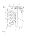
図1に示す画像形成装置200は、例えばタンデム式のカラー電子写真プリンタとしての構成を備えている。同図に示すよう、画像形成装置200は、印刷媒体を収納する用紙カセット202、用紙カセット202に収納されている印刷媒体を送り出す給紙ローラ270、用紙カセット202から搬送される印刷媒体を1枚ずつ分離するための分離フレーム260、用紙カセット202から搬送される印刷媒体の傾きを矯正する印刷スキュー矯正機構203、感光体ドラム211aを備えてその周面にブラックのトナー画像を形成する画像形成ユニット(K)211、同じく感光体ドラム212aの周面にイエローのトナー画像を形成する画像形成ユニット(Y)212、同じく感光体ドラム213aの周面にマゼンタのトナー画像を形成する画像形成ユニット(M)213、同じく感光体ドラム214aの周面にシアンのトナー画像を形成する画像形成ユニット(C)214、後述するように転写器771〜774を有して印刷スキュー矯正機構203を通過した印刷媒体を搬送しつつ各色のトナー画像を順次転写するための転写ベルトユニット220、及び印刷媒体上に転写されたトナー画像を印刷媒体に熱と圧力により定着する定着装置230等で構成される。
An
また同図に示すように、画像形成装置200には増設給紙ユニット250が配置され、増設給紙ユニット250は、印刷媒体を収納する用紙カセット204と、用紙カセット204に収納されている印刷媒体を送り出す給紙ローラ2702、用紙カセット204から搬送される印刷媒体を1枚ずつ分離するための分離フレーム2602、及び用紙カセット204から搬送されてきた印刷媒体の傾きを矯正する印刷スキュー矯正機構2032等で構成されている。
As shown in the figure, the
尚、給紙ローラ270及び分離フレーム260は用紙繰り出し部であり、印刷スキュー矯正機構203、2032と供に給紙装置と呼ぶことがある。
Note that the
尚、同図中のXYZ座標は、印刷媒体が各画像形成ユニット211〜214を通過する際の搬送方向にX軸をとり、感光体ドラム211a〜214aの回転軸方向にY軸をとり、これら両軸と直交する方向にZ軸をとっている。また、後述する他の図においてXYZ座標が示される場合、これらの座標の軸方向は、共通する方向を示すものとする。即ち、各図のXYZ軸は、各図の描写部分が、図1に示す画像形成装置200を構成する際の配置方向を示している。
Note that the XYZ coordinates in the figure take the X axis in the transport direction when the print medium passes through each of the
次に、増設給紙ユニット250の、本発明に基づく印刷スキュー矯正機構2032の構成について説明する。図2は、図1に示す増設給紙ユニット250の印刷スキュー矯正機構2032を、図1の視角を基準とする手前側右上方からみた外観斜視図であり、図3は、同奥側右上方からみた外観斜視図である。また図4及び図7は図2の部分拡大図であり、図5は図3の部分拡大図である。更に、図6は図4に対応する部分を、図1の視角を基準とする奥側左上方からみた斜視図であり、図8は図7に対応する部分を、同手前側左上方からみた斜視図である。
Next, the configuration of the print
図2、図3に示すように、印刷スキュー矯正機構2032は、矢印A方向から搬送されてきた印刷媒体の印刷スキューを矯正するレジストローラ31と加圧ローラ32、レジストローラ31の両端部の軸受カラ1005、加圧ローラ32の両端部の軸受カラ1006、移動ホルダ1001、ベースフレーム1000等を備えている。またレジストローラ31の駆動ギヤ列側の一方の端部31aは、軸受カラ1005を介してベースフレーム1000にガタ無く保持され、他方の端部31bは、軸受カラ1005を介して移動ホルダ1001にガタ無く保持されている。更に、加圧ローラ32の駆動ギヤ列側の一方の端部32aは軸受カラ1006を介してレジストローラ31側に移動可能にベースフレーム1000に保持され、他方の端部32bは軸受カラ1006を介してレジストローラ31側に移動可能に移動ホルダ1001に保持されている。尚、レジストローラ31と加圧ローラ32のローラ対をレジストローラ対と呼ぶことがある。
As shown in FIGS. 2 and 3, the print
スプリング34a,34bは、レジストローラ31に加圧ローラ32を押圧するためのもので、駆動ギヤ側のスプリング34aは、図7及び図8に示すように、その両端がベースプレート1000に形成された2つスプリングフック部1000aと1000b(図8)に係止され、加圧ローラ32の軸受カラ1006を抱き込むように配置されている。他方のスプリング34bは、図5及び図6に示すように、その両端が移動ホルダ1001に形成された2つのスプリングフック部1001bと1001c(図6)に係止され、加圧ローラ32の軸受カラ1006を抱き込むように配置されている。この2つのスプリング34a、34bの作用により、加圧ローラ32は適度な押圧によりレジストローラ31と当接している。
The
図4に示すように、カム1002は、そのカム面1002aが移動ホルダ1001のカム受面1001aに当接するように、ベースプレート1000から切起こされたホルダ部1000fの背面部1000gに回転可能に保持され、移動ホルダ1001とベースプレート1000間には2つのスプリング1004が張架されている。2つのスプリング1004の一端は移動ホルダ1001に形成されたポスト1001dと1001eに保持され、もう一端はベースプレート1000に形成されたフック部1000cと1000dに保持されている。これにより移動ホルダ1001は、常に下方(Z軸のマイナス方向)に付勢されている。
As shown in FIG. 4, the
移動ホルダ1001は、ベースプレート1000から切起こされて断面コ字状に形成されたホルダ部1000fに設けられたレール部1000eに沿って印刷媒体搬送方向(図2の矢印A方向)に移動可能に保持されている。従って、カム1002のカム面1002aは、移動ホルダ1001のカム受面1001aの上部と圧接し、固定ネジ1003にて任意の角度で固定できるように設けられている。また、移動ホルダ1001には、図4に示すように、カム1002の回転角をマイナス4からプラス4までの9段階で示す目盛1001gが表示され、カム1002には、一体的に回転して目盛1001gを指すことによってその回転角を示すマーク1002bが備えられている。尚、移動ホルダ1001、カム1002、スプリング1004、目盛1001g、マーク1002b、及び固定ネジ1003等が傾き調整手段に相当する。
The
以上の構成において、各部の動作について更に説明する。
図1に示す画像形成装置200において、印刷媒体は、用紙カセット202から給紙ローラ270と分離フレーム260により一枚ずつに捌かれて送り出される。給紙された印刷媒体は、印刷スキュー矯正機構203に突き当てられ印刷スキューが矯正された後、転写ベルトユニット220によって搬送され、4色の画像形成ユニット(K)211〜画像形成ユニット(C)214によって形成された各色のトナー現像が順次重ねて転写される。次に、印刷媒体は転写されたトナーを定着させるために定着装置230に搬入され、定着装置230内を通過する時に熱と圧力により印刷媒体上にトナーが定着し、トナーが定着した印刷媒体は画像形成装置200から排出され、印刷は完了する。
In the above configuration, the operation of each unit will be further described.
In the
増設給紙ユニット250は、画像形成装置200本体と同様に印刷媒体を収納する用紙カセット204を備えており、画像形成装置200本体と同様に給紙ローラ2702と分離フレーム2602によって、用紙カセット204から印刷媒体を一枚ずつに捌いて送り出す。給紙ローラ2702によって搬送された印刷媒体は、増設給紙ユニット250内の印刷媒体搬送ルート上に設置された印刷スキュー矯正機構2032に突き当てられて印刷スキューが矯正される。その後印刷媒体は、画像形成装置200本体に搬送され、上述した印刷プロセスと同様の手順で印刷が行われるが、このように増設給紙ユニット250から印刷媒体が搬送される場合、前記した画像形成装置200本体の印刷スキュー矯正機構203による印刷媒体の突き当ては行わない。従って、ここでの印刷媒体は印刷スキュー矯正機構203を通過するのみとなる。
The additional
尚、ここでいう印刷スキューとは、例えば印刷部の平行に配置された画像形成ユニット211〜214の各感光体ドラム211a〜214aの回転軸方向(Y軸方向)と直交する方向に対する印刷媒体の傾きをいう。
Note that the print skew here refers to, for example, the printing medium in a direction orthogonal to the rotation axis direction (Y-axis direction) of the
以後、各感光体ドラム212a〜214aの回転軸方向(Y軸方向)を単に印刷部の回転軸方向と称す。従って、後述するように、印刷部の回転軸方向に対して印刷スキュー矯正機構2032のレジストローラ31及び加圧ローラ32の回転軸が平行に配置されていないと、印刷スキュー矯正機構2032によって印刷スキューを正しく矯正することができない。また、印刷部の回転軸方向に対して印刷スキュー矯正機構2032のレジストローラ31及び加圧ローラ32の回転軸が平行に配置されている場合のレジストローラ31及び加圧ローラ32(レジストローラ対)の状態を、以後理想状態と称す。
Hereinafter, the rotation axis direction (Y-axis direction) of each of the photosensitive drums 212a to 214a is simply referred to as the rotation axis direction of the printing unit. Therefore, as will be described later, if the rotation axes of the
図2において、印刷スキュー矯正機構2032は、矢印A方向に搬送される印刷媒体の先端の両端部が、回転していないレジストローラ31と加圧ローラ32の接合部に共に当接した後に回転を開始し、印刷媒体の先端部が印刷スキュー矯正機構2032の軸方向と平行となった状態で媒体搬送を開始する。従って、印刷スキュー矯正機構2032を、搬送する印刷媒体の記録面側(矢印B方向)から見たとき、例えばその右側が、理想状態に対して上流側(図2の場合、Z軸マイナス方向)に傾いている場合、印刷媒体はやや右にずれた方向に送り出され、その結果、左側が先行して搬送されることとなり、後述するように、印刷結果として左側の先端書出位置が大きくなってしまう。
In FIG. 2, the print
逆に、印刷スキュー矯正機構2032の左側が、理想状態に対して上流側(図2の場合、Z軸マイナス方向)に傾いている場合、印刷媒体はやや左にずれた方向に送り出され、その結果、右側が先行して搬送されることとなり、後述するように、印刷結果として右側の先端書出位置が大きくなってしまう。
Conversely, if the left side of the print
次に、カム1002の回転位置を示す説明図である図9〜図12を参照しながら印刷スキュー矯正機構2032における傾き調整機構の動作について説明する。
Next, the operation of the tilt adjustment mechanism in the print
通常(例えば工場出荷時)、カム1002は、図9に示すように、そのマーク1002bがホルダ1001の目盛1001gの“0”を指す位置に調整されている。この位置は、カム1002を回転調整することによって、ベースフレーム1000に対する移動ホルダ1001の高さが調整できる調整範囲の略中位に相当する。また図11に示すように、そのマーク1002bがホルダ1001の目盛1001gの“−4”を指す位置に調整されるとき、ベースフレーム1000に対する移動ホルダ1001の高さは最下位位置となり、また図12に示すように、そのマーク1002bがホルダ1001の目盛1001gの“4”を指す位置に調整されるとき、ベースフレーム1000に対する移動ホルダ1001の高さは最高位位置となる。
Normally (for example, at the time of factory shipment), the
従って、図2の矢印B方向からみたとき、印刷スキュー矯正機構2032の右側が、理想状態に対して上流側(図2の場合、Z軸マイナス方向)に傾いている場合、上記したように印刷結果として左側の先端書出位置が大きくなる印刷スキューが発生するが、このときカム1002の固定ネジ1003を緩め、カム1002を反時計方向に回転させて移動ホルダ1001を下方に移動してレジストローラ対の左側を上流側に移動し、理想状態となる、例えば、カム1002のマーク1002bが移動ホルダ1001の目盛1001gの例えばマイナス2(図10参照)を指す位置で固定ネジ1003を締めてその位置に固定する。尚、印刷スキュー矯正機構2032の同方向への調整は、前記したように、最大、マーク1002bがホルダ1001の目盛1001gの“−4”を指す位置(図11参照)まで可能である。
Accordingly, when the right side of the print
以上のように、印刷スキュー矯正機構2032のレジストローラ対の左側が、印刷媒体搬送方向において上流側に調整されることにより、印刷媒体の左側が先行することなく印刷され、印刷スキューが解消される。
As described above, the left side of the registration roller pair of the print
一方、図2の矢印B方向からみたとき、印刷スキュー矯正機構2032の左側が、理想状態に対して上流側(図2の場合、Z軸マイナス方向)に傾いている場合、上記したように印刷結果として右側の先端書出位置が大きくなる印刷スキューが発生するが、このとき、カム1002の固定ネジ1003を緩め、カム1002を時計方向に回転させて移動ホルダ1001を上方に移動してレジストローラ対の左側を下流側に移動し、理想状態となる、例えば、カム1002のマーク1002bが移動ホルダ1001の目盛1001gの例えばプラス2(図10参照)を指す位置で固定ネジ1003を締めてその位置に固定する。尚、印刷スキュー矯正機構2032の同方向への調整は、前記したように、最大、マーク1002bがホルダ1001の目盛1001gの“4”を指す位置(図12参照)まで可能である。
On the other hand, when the left side of the print
以上のように、印刷スキュー矯正機構2032のレジストローラ対の左側が、印刷媒体搬送方向において下流側に調整されることにより、印刷媒体の右側が先行することなく印刷され、印刷スキューが解消される。
As described above, the left side of the registration roller pair of the print
次に、印刷媒体にスキュー調整用印刷パターンを印刷することにより、上記した印刷スキューを解消するための調整を容易にする方法について、図13から図15までの印刷パターン図を参照しながら以下に説明する。 Next, a method for facilitating adjustment for eliminating the above-described print skew by printing a skew adjustment print pattern on a print medium will be described below with reference to the print pattern diagrams of FIGS. explain.
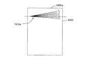
図13は、カム1002が、図9に示すように、そのマーク1002bがホルダ1001の目盛1001gの“0”を指す位置(以後基準位置と称す)に調整されている状態において、レジストローラ対が理想状態にあって印刷スキューがないとき、印刷媒体4005に印刷されたスキュー調整用印刷パターン1510の印刷結果を示している。この時、表示「0」に対応する直線が印刷媒体の先端部4005aと平行に印刷されている。このように、スキュー調整用印刷パターン1510は、表示「0」に対応する直線を中心にして、所定の角度付けされた表示「−4」から表示「4」までに対応する9本の直線からなる。
FIG. 13 shows a state where the pair of registration rollers is in a state where the
尚、図13で、参考線1500は、印刷スキュー矯正機構2032のレジストローラ対が理想状態にあるとき、印刷媒体4005が印刷スキュー矯正機構2032によって搬送される媒体搬送方向を示し、点線、或いは一点鎖線で示された印刷媒体4005は、印刷媒体4005が印刷スキュー矯正機構2032によって、印刷スキューが発生する傾いた状態で印刷スキュー矯正機構2032から搬送される場合の様子を示している。
In FIG. 13, a
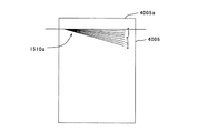
図14は、図13に点線で示すように、印刷媒体4005の左側が先行して搬送される印刷スキューが生じている印刷媒体4005に印刷されたスキュー調整用印刷パターン1510aの印刷結果を示している。この場合、図13に点線で示すように、左側が先行した状態で所定の印刷位置に至ったとき、図13に示すスキュー調整用印刷パターン1510aが印刷されることになるため、その印刷結果は、図14に示すように、左側の先端書出位置が大きくなってしまう。
FIG. 14 shows a print result of the skew
また、印刷媒体4005に印刷されるスキュー調整用印刷パターン1510aの表示「−4」から「+4」までに対応する9本の各直線は、前記した移動ホルダ1001の目盛1001g(図9)に対応して設定されたもので、カム1002の回転位置を基準位置からプラス或いはマイナス方向に移動したとき、そのときマーク1002bが指す数に応じて、「0」に対応する直線が傾く位置を示すように予め考慮して設定されている。
Also, each of the nine straight lines corresponding to the display “−4” to “+4” of the skew
従って、例えば、図14に示すように、スキュー調整用印刷パターン1510aの表示「−2」に対応する直線が印刷媒体4005の先端4005aと平行になっている場合、カム1002を、図9に示す基準位置から図10に示すように、マーク1002bがホルダ1001の目盛“−2”を指す位置まで反時計方向に回転し、印刷スキュー矯正機構2032のレジストローラ対の左側(図2の矢印B方向から見たとき)を、印刷媒体搬送方向において上流側に所定量調整して固定することによって、スキュー調整用印刷パターン1510aの表示「0」に対応する直線が印刷媒体4005の先端4005aと平行になって、印刷スキューが解消できるようになっている。
Therefore, for example, as shown in FIG. 14, when the straight line corresponding to the display “−2” of the skew
同様にして、スキュー調整用印刷パターン1510aの表示「−4」に対応する直線が印刷媒体4005の先端4005aと平行になっている場合、カム1002を、図9に示す基準位置から図11に示すように、マーク1002bがホルダ1001の目盛“−4”を指す位置まで反時計方向に回転し、固定することによって、スキュー調整用印刷パターン1510aの表示「0」に対応する直線が印刷媒体4005の先端4005aと平行になって、印刷スキューを解消することができる。
Similarly, when the straight line corresponding to the display “−4” of the skew
一方、図15は、図13に一点鎖線で示すように、印刷媒体4005の右側が先行して搬送される印刷スキューが生じている印刷媒体4005に印刷されたスキュー調整用印刷パターン1510aの印刷結果を示している。この場合、図13に一点鎖線で示すように、右側が先行した状態で所定の印刷位置に至ったとき、図13に示すスキュー調整用印刷パターン1510aが印刷されることになるため、その印刷結果は、図15に示すように、右側の先端書出位置が大きくなってしまう。
On the other hand, FIG. 15 shows a print result of the skew
このとき、図15に示すように、スキュー調整用印刷パターン1510aの表示「4」に対応する直線が印刷媒体4005の先端4005aと平行になっている場合、カム1002を、図9に示す基準位置から図12に示すように、マーク1002bがホルダ1001の目盛“4”を指す位置まで時計方向に回転し、印刷スキュー矯正機構2032のレジストローラ対の左側(図2の矢印B方向から見たとき)を、印刷媒体搬送方向において下流側に所定量調整して固定することによって、スキュー調整用印刷パターン1510aの表示「0」に対応する直線が印刷媒体4005の先端4005aと平行になって、印刷スキューが解消できる。
At this time, as shown in FIG. 15, when the straight line corresponding to the display “4” of the skew
尚、ここでは、スキュー調整用印刷パターンが、パーソナルコンピュータ等の外部機器から画像形成装置に送信されるものとするが、これに限定されるものではなく、スキュー調整用印刷パターンを画像形成装置内の不揮発性記憶装置に格納しておき、スキュー調整時に記憶装置からスキュー調整用パターンを呼び出して印刷する構成としても良い。 Here, it is assumed that the skew adjustment print pattern is transmitted from an external device such as a personal computer to the image forming apparatus. However, the present invention is not limited to this, and the skew adjustment print pattern is stored in the image forming apparatus. It is also possible to store the data in the non-volatile storage device and call the skew adjustment pattern from the storage device to perform printing at the time of skew adjustment.
また、上記した例では、図1に示すように、画像形成装置200本体に増設給紙ユニット250が一台増設されている例を示したが、増設給紙ユニット250の下面には、更に複数の増設給紙ユニット250を増設可能であり、図16には、増設給紙ユニット250の下に更に1台の増設給紙ユニット250を増設した例を示している。
In the above example, as shown in FIG. 1, an example in which one additional
以上のように、本実施の形態の画像形成装置によれば、印刷部の回転軸方向に対する印刷スキュー矯正機構のレジストローラ対の平行度を確保できるため、印刷スキューのない画像形成装置を提供することができる。また、画像形成装置を長期にわたり使用したとき、レジストローラ対の左右のローラ軸受部が不均一に磨耗して加圧ローラの抑圧のバランスが保たれず印刷スキューを発生させてしまうなど部品の経時的な変化によって印刷スキューが発生してしまう可能性もあるが、そのような場合であっても、印刷部の回転軸方向に対するレジストローラ対の傾き調整により、印刷スキューを解消し、再び印刷品質の優れた画像形成装置を提供することができる。 As described above, according to the image forming apparatus of the present embodiment, since the parallelism of the registration roller pair of the printing skew correction mechanism with respect to the rotation axis direction of the printing unit can be ensured, an image forming apparatus with no printing skew is provided. be able to. In addition, when the image forming apparatus is used for a long period of time, the left and right roller bearing portions of the registration roller pair wear unevenly, and the balance of suppression of the pressure roller is not maintained, and printing skew is generated. However, even in such a case, the print skew can be eliminated by adjusting the inclination of the registration roller pair with respect to the rotation axis direction of the printing unit, and the print quality can be restored again. It is possible to provide an excellent image forming apparatus.
また、画像形成装置200本体の印刷部に対する位置ずれ等の発生しやすい増設給紙ユニット250に印刷スキュー矯正機構が配置されている場合にも、印刷部の回転軸方向に対する印刷スキュー矯正機構のレジストローラ対の平行度を確保できるため有利である。
In addition, even when the print skew correction mechanism is arranged in the additional
実施の形態2.
上記した実施の形態1の画像形成装置におけるレジストローラ対の傾き調整は、機構部の分解を伴う調整作業であるため、作業性が悪く、保守サービスマンの手を煩わせるという問題点があった。本実施の形態では、この問題を解消するための画像形成装置を提供する。
Embodiment 2. FIG.
The adjustment of the inclination of the registration roller pair in the image forming apparatus according to the first embodiment described above is an adjustment operation that involves disassembly of the mechanism, and thus there is a problem in that the workability is poor and the maintenance serviceman is troubled. . In the present embodiment, an image forming apparatus for solving this problem is provided.
図17は、本発明に基づく実施の形態2の画像形成装置に採用される印刷スキュー矯正機構4000の構成を示す外観斜視図である。
FIG. 17 is an external perspective view showing the configuration of a print
この印刷スキュー矯正機構4000を採用する画像形成装置が、前記した図2に示す実施の形態1の印刷スキュー矯正機構2032を採用する画像形成装置と主に異なる点は、カムの回転駆動機構を設けた点と、画像形成装置の制御系にこのカムの回転駆動機構を制御する制御部を新たに追加した点である。従って、この印刷スキュー矯正機構4000を採用する画像形成装置が、前記した実施の形態1の画像形成装置200(図1)と共通する部分には同符号を付して、或いは図面を省いて説明を省略し、異なる点を重点的に説明する。尚、本実施の形態の画像形成装置の要部構成は、図1に示される実施の形態1の画像形成装置200の範囲において、印刷スキュー矯正機構4000(図1では2032)以外では共通するため、必要に応じて図1を参照する。
The image forming apparatus adopting the print
従って、図17は、印刷スキュー矯正機構4000を、図1の視角を基準とする手前側右上方からみた外観斜視図、そして図18は図17の部分拡大図、図19はカムの回転駆動機構を分解した分解斜視図である。
Accordingly, FIG. 17 is an external perspective view of the print
図17に示すように、印刷スキュー矯正機構4000は、矢印A方向から搬送されてきた印刷媒体の印刷スキューを矯正するレジストローラ31と加圧ローラ32、レジストローラ31の両端部の軸受カラ1005、加圧ローラ32の両端部の軸受カラ1006、移動ホルダ1001、ベースフレーム1000等を備えている。またレジストローラ31の駆動ギヤ列側の一方の端部31aは、軸受カラ1005を介してベースフレーム1000にガタ無く保持され、他方の端部31bは、軸受カラ1005を介して移動ホルダ1001にガタ無く保持されている。更に、加圧ローラ32の駆動ギヤ列側の一方の端部32aは軸受カラ1006を介してレジストローラ31側に移動可能にベースフレーム1000に保持され、他方の端部32bは軸受カラ1006を介してレジストローラ31側に移動可能に移動ホルダ1001に保持されている。
As shown in FIG. 17, the print
スプリング34a,34bは、レジストローラ31に加圧ローラ32を押圧するためのもので、駆動ギヤ側のスプリング34aは、その両端がベースプレート1000に形成された2つスプリングフック部1000aと1000b(図7及び図8参照)に係止され、加圧ローラ32の軸受カラ1006を抱き込むように配置されている。他方スプリング34bは、その両端が移動ホルダ1001に形成された2つのスプリングフック部1001bと1001c(図5及び図6参照)に係止され、加圧ローラ32の軸受カラ1006を抱き込むように配置されている。この2つのスプリング34a,34bの作用により、加圧ローラ32は適度な押圧によりレジストローラ31と当接している。
The
図18又は図19に示すように、カム1002は、カム面1002aが移動ホルダ1001のカム受面1001aに当接するように配置され、移動ホルダ1001とベースプレート1000間には2つのスプリング1004が張架されている。2つのスプリング1004の一端は移動ホルダ1001に形成されたポスト1001dと1001eに保持され、もう一端はベースプレート1000に形成されたフック部1000cと1000dに保持されている。これにより移動ホルダ1001は、常に下方(Z軸のマイナス方向)に付勢されている。尚、ここでのカム1002は、前記した実施の形態1の図4で示したカム1002と同一の構成を有し、同様に配置されるものである。
As shown in FIG. 18 or FIG. 19, the
移動ホルダ1001は、ベースプレート1000から切起こされて断面コ字状に形成されたホルダ部1000fに設けられたレール部1000eに沿って印刷媒体搬送方向(図17の矢印A方向)に移動可能に保持されている。ホルダ部1000fの背面部1000gには、カム体3100を回転自在に保持する回転支軸1000hが植立している。
The
カム体3100は、カム1002及びカムギヤ3007が、回転軸3002を同軸として一体的に形成され、回転軸3002には、回転支軸1000hを嵌入する軸孔(図示せず)が形成されている。従ってカム体3100は、その軸孔に回転支軸1000hが嵌入するように装着することによって、回転支軸1000hによって回転自在に支持される。このとき、カム1002は、偏心した状態となり、前記した実施の形態1で説明したようにその回転によって、移動ホルダ1001を所定の範囲内で上下方向にスライド移動する。
In the
カムギヤ3007は、図示しない駆動手段から回転力が伝達されるアイドルギヤ3009と噛合し、回転軸3002の先端部には、等間隔のスリット孔3008aが、周辺部の所定領域に放射方向に複数形成されたスリットディスク3008が同軸で取付けられている。コ字状に形成されたフォトカプラセンサ3010は、スリットディスク3008のスリット孔3008aが形成された部分を挟むように、ベースフレーム1000(図17)に固定され、スリット孔3008aを通過する光を検出することによってスリットディスク3008の回転状態を検出し、カムの回転角情報として後述する印刷制御部700(図20)に送信する。
The
スキュー検知センサ(L)4001,スキュー検知センサ(R)4002(図21参照)は、後述するように、印刷媒体搬送経路上の印刷媒体搬送方向において、印刷スキュー矯正機構4000の下流側の、左側(図17の矢印B方向から見たとき)にスキュー検知センサ(L)4001が、右側にスキュー検知センサ(R)4002が、印刷部の回転軸方向(Y軸方向)と平行な線上にそれぞれ配置されている。尚、これ等のスキュー検知センサ(L)4001及びスキュー検知センサ(R)4002の配置位置は、本給紙装置の給紙可能印刷媒体仕様内の用紙幅を全て網羅する位置である。
As will be described later, the skew detection sensor (L) 4001 and the skew detection sensor (R) 4002 (see FIG. 21) are on the left side, downstream of the print
尚、本発明の給紙装置が、画像形成装置本体に組み込まれている場合、スキュー検知センサ(L)4001及びスキュー検知センサ(R)4002は、印刷媒体搬送方向において、上記条件(つまり、印刷スキュー矯正機構4000の下流側に配置すること)に加え、画像形成ユニット211〜214よりも上流側に配置する必要がある。これは、印刷媒体4005に画像形成ユニット211〜214からトナー像を転写される前に印刷媒体4005のスキューを修正するためである。
When the paper feeding device of the present invention is incorporated in the image forming apparatus main body, the skew detection sensor (L) 4001 and the skew detection sensor (R) 4002 have the above-described conditions (that is, printing) in the print medium conveyance direction. In addition to being arranged downstream of the
図20は、本実施の形態の画像形成装置の本発明に関与する動作を制御する制御系の要部構成を示すブロック図である。 FIG. 20 is a block diagram showing a main configuration of a control system that controls operations related to the present invention of the image forming apparatus of the present embodiment.
同図において、印刷制御部700は、図示しないマイクロプロセッサ、ROM、RAM、入出力ポート、タイマ等によって構成され、上位装置から印刷データ及び制御コマンドを受信して画像形成装置全体をシーケンス制御し、印刷動作を行う。I/F制御部710は、上位装置ヘプリンタ情報を送信すると共に、上位装置から入力したコマンドを解析し、上位装置から受信したデータを処理する。受信メモリ720は、上位装置から受信したデータを、I/F制御部710の制御に基づいて色毎に格納し、操作部701は、画像形成装置の状態を表示するためのLED、及び操作者からの指示を画像形成装置へ与えるためのスイッチを備える。各種センサ702は、印刷媒体の搬送位置を検出する複数のセンサ、装置内の温湿度を検出するためセンサ、濃度測定用のセンサ等であり、各センサの出力は印刷制御部700へ入力されている。
In the figure, a
画データ編集メモリ730は、I/F制御部710を介して上位装置から入力した印刷データを画データとして編集するためのものであり、受信メモリ720に一時的に格納された印刷データを受け取って印刷ヘッドヘ送信するために編集処理し、処理されたイメージデータを格納する。
The image
帯電電圧制御部740は、印刷制御部700の指示により帯電器に電圧を印加して感光体ドラム211a〜214a(図1)の表面を帯電させるための制御を行う。帯電電圧制御部740は、色毎に個別に制御を行うため、K帯電電圧制御部、Y帯電電圧制御部、M帯電電圧制御部、及びC帯電電圧制御部を有しており、それぞれK帯電器741、Y帯電器742、M帯電器743、及びC帯電器744への印加電圧を制御している。
The charging
ヘッド制御部750は、画データ編集メモリ730に格納されたイメージデータに従って、帯電された感光体ドラム211a〜214a(図1)表面に、印刷ヘッドにより光を照射して露光し、静電潜像を生成するための制御を行う。ヘッド制御部750は、色毎に個別に制御を行うため、Kヘッド制御部、Yヘッド制御部、Mヘッド制御部、及びCヘッド制御部を有しており、それぞれKヘッド751、Yヘッド752、Mヘッド753、及びCヘッド754へイメージデータを所定のタイミングで送信する制御を行う。
The
現像電圧制御部760は、感光体ドラム211a〜214a(図1)の表面に印刷ヘッドにより生成された静電潜像にトナーを付着させるため、現像器に対し電圧を印加する制御を行う。現像電圧制御部760は、色毎に個別に制御を行うため、K現像電圧制御部、Y現像電圧制御部、M現像電圧制御部、及びC現像電圧制御部を有しており、それぞれK現像器761、Y現像器762、M現像器763、及びC現像器764への印加電圧を制御する。そして、各々の印刷ヘッドで露光された静電潜像部分にトナー現像を形成する。
The development voltage control unit 760 performs control to apply a voltage to the developing device in order to attach toner to the electrostatic latent image generated by the print head on the surface of the
転写電圧制御部770は、感光体ドラム211a〜214a(図1)の表面に生成されたトナー現像を印刷媒体に転写するため、印刷制御部700の指示を受けて転写器771〜774(図1)に対し電圧を印加するための制御を行う。転写電圧制御部770は、色毎に個別に制御を行うため、K転写電圧制御部、Y転写電圧制御部、M転写電圧制御部、及びC転写電圧制御部を有しており、それぞれK転写器771、Y転写器772、M転写器773、及びC転写器774への印加電圧を制御する。そして、各々の現像器で形成されたトナー像を印刷媒体に順次転写する。
The transfer voltage controller 770 receives instructions from the
モータ制御部780は、各感光体ドラム、帯電器、現像器を駆動するためのKモ一タ781、Yモータ782、Mモータ783、Cモータ784を色毎に個別に駆動するためのKモータ制御部、Yモータ制御部、Mモータ制御部、Cモータ制御部を有する。定着制御部790は、印刷媒体に転写されたトナー像を定着するため、印刷制御部700の指示により定着装置230(図1)に内蔵されたヒータヘ電圧を印加するための制御を行う。また、定着装置230の所定部の温度を測定するためのサーミスタ792からの検出温度を受入れ、ヒータをオン・オフ制御する。また検出温度が所定温度に上昇したときに定着装置内のローラを回転駆動させるための定着装置モータ793を制御する。
The motor control unit 780 includes a
スキュー検知センサ(L)4001及びスキュー検知センサ(R)4002は、図21を参照して前記したように、印刷媒体搬送経路上の印刷媒体搬送方向において、印刷スキュー矯正機構4000の下流側の、左側にスキュー検知センサ(L)4001が、右側にスキュー検知センサ(R)4001が、印刷部の回転軸方向と平行な線上にそれぞれ配置されている。そして、それぞれが印刷媒体の先端部が通過するタイミングを印刷制御部700に通知する。
As described above with reference to FIG. 21, the skew detection sensor (L) 4001 and the skew detection sensor (R) 4002 are arranged on the downstream side of the print
フォトカプラセンサ3010は、図18,19を参照して前記したように、スリットディスク3008のスリット孔3008aが形成された部分を挟むように、ベースフレーム1000に固定され、スリット孔3008aを通過する光を検出することによってスリットディスク3008の回転状態を検出し、カムの回転角情報を後述する印刷制御部700に送信する。モータ駆動制御部810は、印刷制御部700の指示により、印刷スキュー矯正機構4000の傾きを調整するカム体3100(図18)を、図示しない伝達系及びアイドルギヤ3009を介して回転するレジストローラ傾き調整モータ813の回転を制御する。尚、ここで、モータ駆動制御部810は、パルス駆動によりレジストローラ傾き調整モータ813を回転駆動し、与えたパルス数に比例したカム体3100の回転量が得られるように構成されているものとする。
As described above with reference to FIGS. 18 and 19, the
搬送モータ制御部800は、図17に示すレジストローラ31の駆動ギヤ列側(同図の矢印B方向から見たときの左側)に配置された図示しないギヤ列を介してレジストローラ31を回転駆動して印刷媒体を矢印A方向に搬送する搬送モータ805を、印刷制御部700の指示により回転制御する。
The conveyance
以上の構成において、本実施の形態による画像形成装置の印刷スキュー矯正機構4000の傾き調整機構の動作について説明する。
The operation of the tilt adjustment mechanism of the print
図21は、スキュー検知センサ(L)4001及びスキュー検知センサ(R)4002によって、印刷スキュー矯正機構4000によって送り出された印刷媒体4005の印刷スキューを検出する検出方法を説明するための説明図であり、印刷スキュー矯正機構4000を、搬送する印刷媒体の記録面側(図17の矢印B方向)から見た模式図である。同図では、簡単のため、印刷スキュー矯正機構4000のレジストローラ31及び加圧ローラ32の各回転軸方向を、これらに平行なレジストローラ対4010の中心線(同図に一点鎖線で示す)の方向として表している。
FIG. 21 is an explanatory diagram for explaining a detection method for detecting the print skew of the
また、同図中の矢印Fは、印刷部の回転軸方向に対して印刷スキュー矯正機構4000のレジストローラ対4010が平行に配置された理想状態において、印刷媒体4005が印刷スキュー矯正機構4000によって搬送される媒体搬送方向を示し、以後この媒体搬送方向を基準の媒体搬送方向と称す。
Further, an arrow F in the figure indicates that the
同図に示すように、印刷媒体4005は、印刷スキュー矯正機構4000によって、印刷スキューが矯正された後、印刷スキュー矯正機構4000により搬送される。
尚、印刷スキュー矯正機構4000は、印刷媒体4005の先端部4005aを、印刷スキュー矯正機構4000のレジストローラ対4010の軸方向に揃えた状態で送り出すため、レジストローラ対4010の回転軸方向が印刷部の回転軸方向(Y軸方向)と一致していない場合には、印刷スキューは解消されない。従って、ここでいう矯正とは、印刷スキュー矯正機構4000が、印刷媒体4005の先端部4005aを、印刷スキュー矯正機構4000のレジストローラ対4010の軸方向に揃えた状態で送り出す行為を意味するものとする。
As shown in the figure, the
The print
印刷スキュー矯正機構4000により搬送される印刷媒体4005は、その先端部4005aが、スキュー検知センサ(L)4001及びスキュー検知センサ(R)4002を通過する。スキュー検知センサ(L)4001及びスキュー検知センサ(R)4002は、それぞれ印刷媒体4005の先端部4005が通過したタイミング検出し、検出した通過タイミング情報を印刷制御部700に送信する。印刷制御部700は、スキュー検知センサ(L)4001及びスキュー検知センサ(R)4002から送られてくる通過タイミング情報から、通過する印刷媒体4005の印刷スキュー量を検出する。以下、図21を参照しながらその検出方法について説明する。
The
印刷スキュー量は、印刷媒体4005の搬送経路の左右に配置されたスキュー検知センサ(L)4001とスキュー検知センサ(R)4002を、印刷媒体先端部4005aが通過するときの時間差により判定される。図21(a)に示すように、印刷スキュー量がない場合は、両方のスキュー検知センサ4001,4002が、同時に印刷媒体4005を検知する。しかし、図21(b)に示すように印刷媒体4005の左側が先行するような印刷スキューが発生した場合、スキュー検知センサ(L)4001がスキュー検知センサ(R)4002より先に印刷媒体4005を検知する。印刷媒体先端の通過時間差Sは、図21(c)に示すように、印刷媒体先端がスキュー検知センサ(L)4001を通過した時刻をS1、印刷媒体先端がスキュー検知センサ(R)4002を通過した時刻をS2とすると、その時間差Sは、
S=S2−S1 ・・・(1)
から求まる。レジストローラ傾き調整制御部810(図20)は、この時間差Sに基づいて、後述するように、レジストローラ傾き調整用モータ813を駆動して印刷スキュー矯正機構4000の傾き角度の調整をする。
The amount of print skew is determined by the time difference when the print
S = S2-S1 (1)
Obtained from Based on this time difference S, the registration roller inclination adjustment control unit 810 (FIG. 20) drives the registration roller
次にカム1002のホームポジションについて説明する。
Next, the home position of the
カム1002のホームポジションは、後述する所定の回転範囲において、印刷スキュー矯正機構4000のレジストローラ対4010の左側が基準の媒体搬送方向(矢印F方向)における下流側に最大量移動する位置とする。従って、ホームポジションからレジストローラ傾き調整用モータ813が例えば負方向回転駆動されて、カム1002が反時計方向(図18において)に回転すること、印刷スキュー矯正機構4000のレジストローラ対4010の左側が下流側から上流側へと移動する。尚、このときのカム1002の回転量は、印刷スキュー量に応じて決定される。
The home position of the
次に、印刷スキュー量からカム1002の回転量、つまりレジストローラ傾き調整用モータ813のパルス数の決定方法の例を説明する。
Next, an example of a method for determining the rotation amount of the
スキュー検知センサ(L)4001及びスキュー検知センサ(R)4002の各印刷媒体検出によって、この検出時間差Sを前述の式(1)より求める。次にこの時間差に所定係数Tを掛けることにより、印刷スキュー矯正機構4000の傾き補正パルス数TSが決定される。この補正パルス数TSに、カム1002のホームポジションから現在のカム位置までに要するパルス数TOを加えることにより、レジストローラ傾き調整用モータ813の駆動パルス数TMが決定される。以下に上記内容の式を記す。
TS=S×T ・・・(2)
TM=TS+TO ・・・(3)
尚、基本パルス数TOの追加は、後述するように、カム1001を一端ホームポジションに戻してからカム位置を調整するためである。
This detection time difference S is obtained from the above-described equation (1) by detecting each print medium of the skew detection sensor (L) 4001 and the skew detection sensor (R) 4002. Then by applying a predetermined coefficient T to the time difference, the inclination correction pulse number T S of the printing
T S = S × T (2)
T M = T S + T O (3)
Incidentally, additional basic pulse number T O, as described later, in order to adjust the cam position after returning the
更に印刷スキュー矯正機構4000の傾き調整機構の動作について説明する。印刷スキューにおいて、図21(b)に示すように、印刷媒体4005の左側が先行して搬送されて印刷結果として左側の先端書出位置が大きくなっている場合、印刷スキュー矯正機構4000のレジストローラ対4010の左側が、基準の媒体搬送方向(矢印F方向)におい下流側に傾いていることとなる。このため、印刷スキュー矯正機構4000は、レジストローラ対4010の左側を上流側に移動するように自動調整する。この自動調整は以下のようにして実行される。
Further, the operation of the tilt adjustment mechanism of the print
先ず、スキュー検知センサ(L)4001及びスキュー検知センサ(R)4002による印刷媒体検出に基づいて、上式(2)により、傾き補正パルス数TSを求める。次に、現在のカム位置の、ホームポジションからの位置を認識するため、一端カム位置をホームポジションに戻す。このため、レジストローラ傾き調整用モータ813を正方向回転駆動してカム1002とスリットディスク3008、即ちカム体3100を時計方向(図18において)に回転する。この時、フォトカプラセンサ3010によりスリットディスク3008のスリット孔3008aが読み取られるが、スリットディスク3008には所定の範囲にしかスリット孔3008aが形成されていないため、やがてフォトカプラセンサ3010からの信号に変化が得られなくなる。印刷制御部700は、フォトカプラセンサ3010からの信号が変化しなくなった時点でホームポジションであると認識し、レジストローラ傾き調整用モータ813の駆動を停止する。
First, based on the print medium detected by the skew detection sensor (L) 4001 and a skew detection sensor (R) 4002, from the above equation (2), determining the tilt correction pulse number T S. Next, in order to recognize the current cam position from the home position, the cam position is returned to the home position. For this reason, the registration roller
このため、図18に示すスリットディスク3008は、形成されたスリット孔3008aの、右側端部がフォトカプラセンサ3010によって検出される位置にあるとき、カム1002の回転位置がホームポジションとなるように、取付け時に、予め回転角度が調整されるものである。尚、印刷制御部700は、カム1002とスリットディスク3008が時計方向回転を開始してからの駆動パルス数を前記した基本パルス数TOとして保存する。
Therefore, in the
次にレジストローラ傾き調整用モータ813は、負方向回転駆動され、カム体3100を反時計方向(図18において)に、且つ前記した上式(3)で求めたパルス数TMに相当する回転角だけ回転して停止する。従って、このときのカム体3100の回転のうち、パルスTOに相当する回転によって、印刷スキュー矯正機構4000のレジストローラ対4010が、図21(b)に示す状態となるまでその左側を上流側に移動し、更にパルスTSに相当する回転によって、印刷スキューが解消される図21(a)に示す状態となるまでレジストローラ対4010の左側を更に上流側へ移動する。
Then the registration rollers
一方、印刷媒体4005の右側が先行して搬送され、印刷結果として右側の先端書出位置が大きくなっている場合には、印刷スキュー矯正機構4000のレジストローラ対4010の左側が、基準の媒体搬送方向(矢印F方向)において上流側に傾いていることとなり、前述の動作と同様にして、印刷スキュー矯正機構4000のレジストローラ対4010の傾きが補正される。この時、ホームポジションからの調整動作において、レジストローラ傾き調整用モータ813は、上式(3)のTSがマイナスの所定値となるため、印刷スキュー矯正機構4000の左側が上流側に傾いている状態となる前の、印刷スキューが解消される図21(a)に示す状態となったタイミングで停止することになる。
On the other hand, when the right end of the
以上のように、本実施の形態の画像形成装置によれば、前記した実施の形態1で述べた効果に加え、センサにより印刷媒体の印刷スキュー量を検知し、その印刷スキュー量により印刷スキュー矯正機構の傾きを自動調整できるので、常に印刷品質の安定した装置を提供することが可能となる。また傾き調整に際して機構部を分解することもないため、保守作業が容易となる。 As described above, according to the image forming apparatus of the present embodiment, in addition to the effects described in the first embodiment, the print skew amount of the print medium is detected by the sensor, and the print skew correction is performed based on the print skew amount. Since the inclination of the mechanism can be automatically adjusted, it is possible to always provide an apparatus with stable print quality. Further, since the mechanism portion is not disassembled at the time of tilt adjustment, maintenance work is facilitated.
実施の形態3.
本実施の形態の画像形成装置は、前記した実施の形態1で示した印刷スキュー矯正機構2032(図2)に、前記した実施の形態2で説明した印刷スキュー検出機構、即ち図13に示すスキュー検知センサ(L)4001とスキュー検知センサ(R)4002、これらの検出に基づいて印刷スキューを算出する手段、及び算出した算出結果を表示する手段を備えた画像形成装置を提案するものである。
Embodiment 3 FIG.
The image forming apparatus according to the present embodiment includes the print skew correction mechanism 2032 (FIG. 2) described in the first embodiment and the print skew detection mechanism described in the second embodiment, that is, the skew illustrated in FIG. The present invention proposes an image forming apparatus including a detection sensor (L) 4001 and a skew detection sensor (R) 4002, a means for calculating a print skew based on these detections, and a means for displaying the calculated result.
本実施の形態では、印刷媒体搬送方向において左側に配置されたスキュー検知センサ(L)4001を印刷媒体先端が通過した時刻S1と、右側に配置されたスキュー検知センサ(R)4002を印刷媒体先端が通過した時刻S2との差S、及び印刷媒体搬送速度Vにより、印刷媒体先端の印刷スキュー量Kを下式によって算出する。
K=(S2−S1)×V ・・・(4)
従って、この印刷スキュー量Kは、図21に示すスキュー検知センサ(L)4001とスキュー検知センサ(R)4002に対応する位置での、基準の媒体搬送方向(矢印F方向)における印刷媒体4005の位置ずれを示すものとして、図示しない表示手段、例えば操作部701の操作パネルに表示される。一方、図4に示す印刷スキュー矯正機構2032の目盛1001gは、この位置ズレ量を補正するに必要な回転位置を示すものして、予め目盛られている。
In the present embodiment, the time S1 when the leading edge of the printing medium passes through the skew detection sensor (L) 4001 arranged on the left side in the printing medium conveyance direction and the skew detection sensor (R) 4002 arranged on the right side are used as the leading edge of the printing medium. The print skew amount K at the front end of the print medium is calculated by the following equation using the difference S from the time S2 when the print medium passes and the print medium conveyance speed V.
K = (S2-S1) × V (4)
Accordingly, the print skew amount K is equal to the
従って、例えば図21(b)に示すように左端先行の印刷スキューによって印刷スキュー量Kとして位置ずれ量「3」が得られた場合、例えば図4においてマーク1002bが、目盛1001gのマイナス方向に3目盛だけ移動するように、固定ネジ1003を緩めてカム位置を調整して固定する。これにより、印刷スキュー矯正機構2032のレジストローラ対のスキュー検知センサ(L)4001に対応する部分において、印刷スキュー量Kに相当する距離だけ上流側に移動し印刷スキュー量Kを解消することができる。
Therefore, for example, as shown in FIG. 21B, when the positional deviation amount “3” is obtained as the print skew amount K by the print skew preceding the left end, for example, the
以上のように、本実施の形態の画像形成装置よれば、例えば配設場所や電力の問題などで、レジストローラ傾き調整用モータ81を配設できない場合でもスキュー検知センサから検知、算出した印刷スキュー量を操作パネル等に表示することで、実施の形態1の場合のようにスキュー調整印刷パターンを印刷することなく、印刷スキュー矯正機構2032の傾きを容易に調整することが可能となる。
As described above, according to the image forming apparatus of the present embodiment, the print skew detected and calculated from the skew detection sensor even when the registration roller tilt adjustment motor 81 cannot be provided due to, for example, the installation location or power problem. By displaying the amount on the operation panel or the like, it is possible to easily adjust the inclination of the print
尚、前記各実施の形態では、画像形成装置に増設された増設給紙ユニットの給紙装置を例にして説明したが、本発明は、装置内に印刷媒体搬送手段を備える画像形成装置や印刷機、複写機、ファクシミリ等にも適用することができる。 In each of the above-described embodiments, the sheet feeding device of the additional sheet feeding unit added to the image forming apparatus has been described as an example. However, the present invention is not limited to an image forming apparatus or a printing medium that includes a printing medium conveying unit in the apparatus. It can also be applied to machines, copiers, facsimiles, and the like.
31 レジストローラ、 31a 一方の端部、 31b 他方の端部、 32 加圧ローラ、 32a 一方の端部、 32b 他方の端部、 34a,34b スプリング、 200 画像形成装置、 202 用紙カセット、 203 印刷スキュー矯正機構、 204 用紙カセット、 211 画像形成ユニット(K)、 211a 感光体ドラム、 212 画像形成ユニット(Y)、 212a 感光体ドラム、 213 画像形成ユニット(M)、 213a 感光体ドラム、 214 画像形成ユニット(C)、 214a 感光体ドラム、 220 転写ベルトユニット、 230 定着装置、 250 増設給紙ユニット、 260 分離フレーム、 270 給紙ローラ、 700 印刷制御部、 701 操作部、 702 各種センサ、 710 I/F制御部、 720 受信メモリ、 730 画データ編集メモリ、 740 帯電電圧制御部、 741 K帯電器、 742 Y帯電器、 743 M帯電器、 744 C帯電器、 750 ヘッド制御部、 751 Kヘッド、 752 Yヘッド、 753 Mヘッド、 754 Cヘッド、 760 現像電圧制御部、 761 K現像器、 762 Y現像器、 763 M現像器、 764 C現像器、 770 転写電圧制御部、 771 K転写器、 772 Y転写器、 773 M転写器、 774 C転写器、 780 モータ制御部、 781 Kモ一タ、 782 Yモ一タ、 783 Mモ一タ、 784 Cモ一タ、 790 定着制御部、 792 サーミスタ、 793 定着装置モータ、 805 搬送モータ、 810 モータ駆動制御部、 813 調整モータ、 1000 ベースフレーム、 1000a,1000b スプリングフック部、 1000c,1000d フック部、 1000e レール部、 1000f ホルダ部、 1000g 背面部、 1000h 回転支軸、 1001 移動ホルダ、 1001a カム受面、 1001b,1001c フック部、 1001d,1001e ポスト、 1001g 目盛、 1002 カム、 1002a カム面、 1002b マーク、 1003 固定ネジ、 1004 スプリング、 1005 軸受カラ、 1006 軸受カラ、 2032 印刷スキュー矯正機構、 2602 分離フレーム、 2702 給紙ローラ、 3002 回転軸、 3007 カムギヤ、 3008 スリットディスク、 3008a スリット孔、 3009 アイドルギヤ、 3010 フォトカプラセンサ、 3100 カム体、 4000 印刷スキュー矯正機構、 4001 スキュー検知センサ(L)、 4002 スキュー検知センサ(R)、 4005 印刷媒体、 4010 レジストローラ対。 31 Registration roller, 31a One end, 31b The other end, 32 Pressure roller, 32a One end, 32b The other end, 34a, 34b Spring, 200 Image forming apparatus, 202 Paper cassette, 203 Print skew Correction mechanism, 204 paper cassette, 211 image forming unit (K), 211a photosensitive drum, 212 image forming unit (Y), 212a photosensitive drum, 213 image forming unit (M), 213a photosensitive drum, 214 image forming unit (C), 214a Photosensitive drum, 220 transfer belt unit, 230 fixing device, 250 additional paper feeding unit, 260 separation frame, 270 paper feeding roller, 700 print control unit, 701 operation unit, 702 various sensors, 710 I F control unit, 720 reception memory, 730 image data editing memory, 740 charging voltage control unit, 741 K charger, 742 Y charger, 743 M charger, 744 C charger, 750 head controller, 751 K head, 752 Y head, 753 M head, 754 C head, 760 development voltage control unit, 761 K development unit, 762 Y development unit, 763 M development unit, 764 C development unit, 770 transfer voltage control unit, 771 K transfer unit, 772 Y Transfer unit, 773 M transfer unit, 774 C transfer unit, 780 motor control unit, 781 K motor, 782 Y motor, 783 M motor, 784 C motor, 790 fixing control unit, 792 thermistor, 793 fixing device motor, 805 transport motor, 810 motor drive control unit, 813 Adjustment motor, 1000 base frame, 1000a, 1000b Spring hook part, 1000c, 1000d hook part, 1000e rail part, 1000f holder part, 1000g back part, 1000h rotating support shaft, 1001 moving holder, 1001a cam receiving surface, 1001b, 1001c Hook part, 1001d, 1001e post, 1001g scale, 1002 cam, 1002a cam surface, 1002b mark, 1003 fixing screw, 1004 spring, 1005 bearing collar, 1006 bearing collar, 2032 printing skew correction mechanism, 2602 separation frame, 2702 feeding roller 3002 Rotating shaft, 3007 Cam gear, 3008 Slit disc, 3008a Slit hole, 30 09 idle gear, 3010 photocoupler sensor, 3100 cam body, 4000 printing skew correction mechanism, 4001 skew detection sensor (L), 4002 skew detection sensor (R), 4005 printing medium, 4010 registration roller pair.
Claims (21)
ローラと該ローラに圧接する加圧ローラから成り、前記搬送手段から搬送された前記媒体のスキューを矯正する媒体スキュー矯正手段と、
前記媒体スキュー矯正手段の前記媒体の搬送方向に対し直角方向での傾きを調整する傾き調整手段と
を有することを特徴とする給紙装置。 Conveying means for conveying the medium;
A medium skew correcting means comprising a roller and a pressure roller in pressure contact with the roller, and correcting the skew of the medium conveyed from the conveying means;
An inclination adjusting means for adjusting an inclination of the medium skew correcting means in a direction perpendicular to the conveyance direction of the medium.
媒体を一枚ずつ搬送する
ことを特徴とする請求項1記載の給紙装置。 The conveying means is
The sheet feeding device according to claim 1, wherein the sheet is conveyed one by one.
用紙カセットに載置された媒体を搬送する
ことを特徴とする請求項2記載の給紙装置。 The conveying means is
The paper feeding device according to claim 2, wherein the medium placed in the paper cassette is transported.
前記給紙装置の前記媒体の搬送路近傍のベース部材に設けられる
ことを特徴とする請求項1乃至3の何れかに記載の給紙装置。 The medium skew correction means includes:
The sheet feeding device according to claim 1, wherein the sheet feeding device is provided on a base member in the vicinity of a conveyance path of the medium of the sheet feeding device.
前記ローラ及び前記加圧ローラを回動自在に保持する保持部材を有する
ことを特徴とする請求項4記載の給紙装置。 The medium skew correction means includes:
The sheet feeding device according to claim 4, further comprising a holding member that rotatably holds the roller and the pressure roller.
前記ベース部材に設けられ、前記媒体の搬送方向に移動可能とするガイド部に設けられる
ことを特徴とする請求項5記載の給紙装置。 The holding member is
The sheet feeding device according to claim 5, wherein the sheet feeding device is provided in a guide portion that is provided on the base member and is movable in a conveyance direction of the medium.
前記ベース部材に設けられる付勢手段により、前記ベース部材に向けて付勢される
ことを特徴とする請求項6記載の給紙装置。 The holding member is
The paper feeding device according to claim 6, wherein the paper feeding device is biased toward the base member by a biasing means provided on the base member.
前記ロ−ラ及び前記加圧ローラの一端側を保持する
ことを特徴とする請求項7記載の給紙装置。 The holding member is
The sheet feeding device according to claim 7, wherein one end side of the roller and the pressure roller is held.
他端が前記ベース部材に回転自在に保持される
ことを特徴とする請求項8記載の給紙装置。 The roller and the pressure roller are
The sheet feeding device according to claim 8, wherein the other end is rotatably held by the base member.
前記ベース部材に回動可能に設けられるカム部材を有し、
前記カム部材は、該カム部材の回転により、前記保持部材を前記媒体の搬送方向に移動する
ことを特徴とする請求項9記載の給紙装置。 The inclination adjusting means includes
A cam member provided rotatably on the base member;
The sheet feeding device according to claim 9, wherein the cam member moves the holding member in a conveyance direction of the medium by rotation of the cam member.
前記カム部材の回転位置を示す回転位置表示手段を有する
ことを特徴とする請求項10記載の給紙装置。 The inclination adjusting means includes
The sheet feeding device according to claim 10, further comprising a rotation position display unit that indicates a rotation position of the cam member.
ことを特徴とする画像形成装置。 An image forming apparatus comprising the paper feeding device according to claim 1.
印刷スキュー量と前記回転位置表示手段に表示される表示位置に関わるスキュー調整用印刷パターンの印刷結果から判断できる
ことを特徴とする請求項12記載の画像形成装置。 The rotational position of the cam member is
The image forming apparatus according to claim 12, wherein the image forming apparatus can be determined from a printing result of a skew adjustment print pattern related to a print skew amount and a display position displayed on the rotation position display unit.
を有することを特徴とする請求項11記載の給紙装置。 The sheet feeding device according to claim 11, further comprising a detecting unit configured to detect a skew amount of the medium on the medium conveyance path.
を有することを特徴とする請求項14記載の給紙装置。 The sheet feeding device according to claim 14, further comprising a calculation unit that calculates the skew amount from a detection result detected by the detection unit.
を有することを特徴とする請求項15記載の給紙装置。 The sheet feeding device according to claim 15, further comprising a display unit configured to display a calculation result of the calculation unit.
前記媒体スキュー矯正手段近傍に設けられる
ことを特徴とする請求項14記載の給紙装置。 The detection means includes
The sheet feeding device according to claim 14, wherein the sheet feeding device is provided in the vicinity of the medium skew correction unit.
ローラと該ローラに圧接する加圧ローラから成り、前記搬送手段から搬送された前記媒体を前記ローラの軸方向と直交する方向に搬送する媒体スキュー矯正手段と、
前記媒体スキュー矯正手段の前記媒体の搬送方向に対する傾きを調整する傾き調整手段と、
前記媒体の搬送路上に媒体のスキュー量を検出する検出手段と、
前記検出結果からスキュー情報を生成する印刷スキュー情報生成部と、
前記印刷スキュー情報により前記媒体スキュー矯正手段の傾き量を決定する傾き調整制御手段と、
前記傾き量に応じて前記傾き調整手段を駆動する駆動手段と
を有することを特徴とする給紙装置。 Conveying means for conveying the medium;
A medium skew correcting means comprising a roller and a pressure roller that is in pressure contact with the roller, and conveying the medium conveyed from the conveying means in a direction perpendicular to the axial direction of the roller;
An inclination adjusting means for adjusting an inclination of the medium skew correcting means with respect to a conveyance direction of the medium;
Detecting means for detecting a skew amount of the medium on the transport path of the medium;
A print skew information generation unit for generating skew information from the detection result;
An inclination adjustment control means for determining an inclination amount of the medium skew correction means based on the print skew information;
And a driving unit that drives the tilt adjusting unit according to the tilt amount.
感光体にトナー像を形成する画像形成ユニットと、
前記トナー像を前記給紙装置から搬送された媒体に転写する転写手段と、
前記媒体に前記トナー像を定着させる定着手段と
を有することを特徴とする画像形成装置。 A paper feeding device according to claim 18,
An image forming unit for forming a toner image on the photoreceptor;
Transfer means for transferring the toner image to a medium conveyed from the paper feeding device;
An image forming apparatus comprising: a fixing unit that fixes the toner image on the medium.
媒体搬送経路において、前記画像形成ユニットよりも上流側に、且つ、前記媒体スキュー矯正手段より下流側であり該媒体スキュー矯正手段近傍に設けられる
ことを特徴とする請求項19記載の画像形成装置。 The detection means includes
The image forming apparatus according to claim 19, wherein the image forming apparatus is provided upstream of the image forming unit and downstream of the medium skew correcting unit and in the vicinity of the medium skew correcting unit in the medium conveyance path.
複数の光学センサから成り、且つ、媒体搬送路に前記感光体の回転軸方向と平行に設けられる
ことを特徴とする請求項19に記載の画像形成装置。 The detection means includes
The image forming apparatus according to claim 19, wherein the image forming apparatus includes a plurality of optical sensors and is provided in a medium conveyance path in parallel with a rotation axis direction of the photosensitive member.
Priority Applications (2)
| Application Number | Priority Date | Filing Date | Title |
|---|---|---|---|
| JP2007225123A JP2009057143A (en) | 2007-08-31 | 2007-08-31 | Paper feeder and image forming device |
| US12/230,378 US20090060609A1 (en) | 2007-08-31 | 2008-08-28 | Medium feeding apparatus and image forming apparatus that employs the image feeding apparatus |
Applications Claiming Priority (1)
| Application Number | Priority Date | Filing Date | Title |
|---|---|---|---|
| JP2007225123A JP2009057143A (en) | 2007-08-31 | 2007-08-31 | Paper feeder and image forming device |
Publications (1)
| Publication Number | Publication Date |
|---|---|
| JP2009057143A true JP2009057143A (en) | 2009-03-19 |
Family
ID=40407772
Family Applications (1)
| Application Number | Title | Priority Date | Filing Date |
|---|---|---|---|
| JP2007225123A Pending JP2009057143A (en) | 2007-08-31 | 2007-08-31 | Paper feeder and image forming device |
Country Status (2)
| Country | Link |
|---|---|
| US (1) | US20090060609A1 (en) |
| JP (1) | JP2009057143A (en) |
Cited By (4)
| Publication number | Priority date | Publication date | Assignee | Title |
|---|---|---|---|---|
| WO2010103830A1 (en) | 2009-03-10 | 2010-09-16 | 三菱マテリアル株式会社 | Biaxial tensile testing machine |
| JP2011252958A (en) * | 2010-05-31 | 2011-12-15 | Kyocera Mita Corp | Cam drive mechanism, belt conveyance device provided with the same, and image forming apparatus provided with the same |
| US8944432B2 (en) | 2012-03-16 | 2015-02-03 | Ricoh Company, Limited | Sheet conveying device and image forming apparatus |
| JP2017095187A (en) * | 2015-11-18 | 2017-06-01 | 京セラドキュメントソリューションズ株式会社 | Image formation apparatus |
Families Citing this family (3)
| Publication number | Priority date | Publication date | Assignee | Title |
|---|---|---|---|---|
| JP5224094B2 (en) | 2007-12-17 | 2013-07-03 | 株式会社リコー | Belt device and image forming apparatus |
| TWI636890B (en) * | 2017-09-22 | 2018-10-01 | 東友科技股份有限公司 | Roller-type lateral force generation device |
| JP2020045183A (en) * | 2018-09-14 | 2020-03-26 | 富士ゼロックス株式会社 | Conveying device and image forming device |
Citations (5)
| Publication number | Priority date | Publication date | Assignee | Title |
|---|---|---|---|---|
| JPH0238243A (en) * | 1988-07-29 | 1990-02-07 | Canon Inc | Sheet transporting device |
| JP2001335166A (en) * | 2000-05-25 | 2001-12-04 | Alps Electric Co Ltd | Paper feeding mechanism of printer |
| JP2003292198A (en) * | 2002-03-29 | 2003-10-15 | Fuji Photo Film Co Ltd | Sheet member delivery device |
| JP2005041604A (en) * | 2003-07-23 | 2005-02-17 | Canon Inc | Sheet carrying device, image forming device and image reader |
| JP2005247553A (en) * | 2004-03-05 | 2005-09-15 | Canon Finetech Inc | Sheet transport device and image forming device |
Family Cites Families (3)
| Publication number | Priority date | Publication date | Assignee | Title |
|---|---|---|---|---|
| US5034781A (en) * | 1989-06-07 | 1991-07-23 | Kabushiki Kaisha Toshiba | Image forming with tilting register rollers to correct alignment |
| FR2708917B1 (en) * | 1993-08-12 | 1995-11-10 | Heidelberger Druckmasch Ag | Device for separating and aligning the upper side of a stack of sheets in a rotary printing machine. |
| US6490421B2 (en) * | 2001-02-12 | 2002-12-03 | Hewlett-Packard Company | Methods and apparatus for correcting rotational skew in duplex images |
-
2007
- 2007-08-31 JP JP2007225123A patent/JP2009057143A/en active Pending
-
2008
- 2008-08-28 US US12/230,378 patent/US20090060609A1/en not_active Abandoned
Patent Citations (5)
| Publication number | Priority date | Publication date | Assignee | Title |
|---|---|---|---|---|
| JPH0238243A (en) * | 1988-07-29 | 1990-02-07 | Canon Inc | Sheet transporting device |
| JP2001335166A (en) * | 2000-05-25 | 2001-12-04 | Alps Electric Co Ltd | Paper feeding mechanism of printer |
| JP2003292198A (en) * | 2002-03-29 | 2003-10-15 | Fuji Photo Film Co Ltd | Sheet member delivery device |
| JP2005041604A (en) * | 2003-07-23 | 2005-02-17 | Canon Inc | Sheet carrying device, image forming device and image reader |
| JP2005247553A (en) * | 2004-03-05 | 2005-09-15 | Canon Finetech Inc | Sheet transport device and image forming device |
Cited By (5)
| Publication number | Priority date | Publication date | Assignee | Title |
|---|---|---|---|---|
| WO2010103830A1 (en) | 2009-03-10 | 2010-09-16 | 三菱マテリアル株式会社 | Biaxial tensile testing machine |
| JP2010210442A (en) * | 2009-03-10 | 2010-09-24 | Mitsubishi Materials Corp | Biaxial tensile testing device |
| JP2011252958A (en) * | 2010-05-31 | 2011-12-15 | Kyocera Mita Corp | Cam drive mechanism, belt conveyance device provided with the same, and image forming apparatus provided with the same |
| US8944432B2 (en) | 2012-03-16 | 2015-02-03 | Ricoh Company, Limited | Sheet conveying device and image forming apparatus |
| JP2017095187A (en) * | 2015-11-18 | 2017-06-01 | 京セラドキュメントソリューションズ株式会社 | Image formation apparatus |
Also Published As
| Publication number | Publication date |
|---|---|
| US20090060609A1 (en) | 2009-03-05 |
Similar Documents
| Publication | Publication Date | Title |
|---|---|---|
| US10358311B2 (en) | Sheet conveying device and image forming apparatus incorporating the sheet conveying device | |
| JP2009057143A (en) | Paper feeder and image forming device | |
| JP2014133634A (en) | Sheet conveyance apparatus and image forming apparatus | |
| JP2008032913A (en) | Image forming apparatus | |
| US11066263B2 (en) | Sheet conveying device and image forming apparatus incorporating the sheet conveying device | |
| US10513408B2 (en) | Sheet conveying device and image forming apparatus incorporating the sheet conveying device | |
| JP2004271746A (en) | Image forming apparatus | |
| JP2008139399A (en) | Image forming apparatus | |
| US10875728B2 (en) | Sheet conveying device, image forming apparatus incorporating the sheet conveying device, and post processing device incorporating the sheet conveying device | |
| US10584008B2 (en) | Sheet conveying device and image forming apparatus incorporating the sheet conveying device | |
| JP4730288B2 (en) | Image forming apparatus | |
| JP6763288B2 (en) | Conveyor device, image forming device | |
| US11445082B2 (en) | Image forming apparatus incorporating position detector and position corrector | |
| US20140153942A1 (en) | Image forming apparatus with endless belt and method for calculating meandering amount of belt | |
| JP4720190B2 (en) | Image forming apparatus | |
| US20080124159A1 (en) | Image forming apparatus | |
| JP2006232516A (en) | Sheet material carrying device and image forming apparatus | |
| JP6768408B2 (en) | Image forming device | |
| JP2007137625A (en) | Sheet carrying device, its control method and image forming device | |
| JP6258175B2 (en) | Image forming apparatus | |
| JP2019001657A (en) | Carrier device and image forming device | |
| JP7034432B2 (en) | Image forming device | |
| JP3899796B2 (en) | Paper conveying apparatus and image forming apparatus | |
| JP5197133B2 (en) | Drive device and paper transport device | |
| JPH0656296A (en) | Belt deviation control method for belt conveying device and its device |
Legal Events
| Date | Code | Title | Description |
|---|---|---|---|
| A977 | Report on retrieval |
Free format text: JAPANESE INTERMEDIATE CODE: A971007 Effective date: 20090615 |
|
| A131 | Notification of reasons for refusal |
Free format text: JAPANESE INTERMEDIATE CODE: A131 Effective date: 20090623 |
|
| A521 | Written amendment |
Free format text: JAPANESE INTERMEDIATE CODE: A523 Effective date: 20090724 |
|
| A02 | Decision of refusal |
Free format text: JAPANESE INTERMEDIATE CODE: A02 Effective date: 20091201 |
|
| A521 | Written amendment |
Free format text: JAPANESE INTERMEDIATE CODE: A523 Effective date: 20100226 |
|
| A911 | Transfer to examiner for re-examination before appeal (zenchi) |
Free format text: JAPANESE INTERMEDIATE CODE: A911 Effective date: 20100304 |
|
| A912 | Re-examination (zenchi) completed and case transferred to appeal board |
Free format text: JAPANESE INTERMEDIATE CODE: A912 Effective date: 20100402 |