EP2073036A1 - Range measuring method, range measuring apparatus, non-contacted IC medium, range measuring system and range measuring program - Google Patents
Range measuring method, range measuring apparatus, non-contacted IC medium, range measuring system and range measuring program Download PDFInfo
- Publication number
- EP2073036A1 EP2073036A1 EP08254035A EP08254035A EP2073036A1 EP 2073036 A1 EP2073036 A1 EP 2073036A1 EP 08254035 A EP08254035 A EP 08254035A EP 08254035 A EP08254035 A EP 08254035A EP 2073036 A1 EP2073036 A1 EP 2073036A1
- Authority
- EP
- European Patent Office
- Prior art keywords
- frequency
- contacted
- medium
- range
- response signal
- Prior art date
- Legal status (The legal status is an assumption and is not a legal conclusion. Google has not performed a legal analysis and makes no representation as to the accuracy of the status listed.)
- Granted
Links
Images




Classifications
-
- G—PHYSICS
- G01—MEASURING; TESTING
- G01S—RADIO DIRECTION-FINDING; RADIO NAVIGATION; DETERMINING DISTANCE OR VELOCITY BY USE OF RADIO WAVES; LOCATING OR PRESENCE-DETECTING BY USE OF THE REFLECTION OR RERADIATION OF RADIO WAVES; ANALOGOUS ARRANGEMENTS USING OTHER WAVES
- G01S13/00—Systems using the reflection or reradiation of radio waves, e.g. radar systems; Analogous systems using reflection or reradiation of waves whose nature or wavelength is irrelevant or unspecified
- G01S13/74—Systems using reradiation of radio waves, e.g. secondary radar systems; Analogous systems
- G01S13/82—Systems using reradiation of radio waves, e.g. secondary radar systems; Analogous systems wherein continuous-type signals are transmitted
- G01S13/84—Systems using reradiation of radio waves, e.g. secondary radar systems; Analogous systems wherein continuous-type signals are transmitted for distance determination by phase measurement
Definitions
- the present invention relates to a range measuring method, a range measuring apparatus, a non-contacted IC medium, a range measuring system and a range measuring program, which measures a range, for example, from a reader unit to a non-contacted IC medium.
- the range measuring apparatus controls an RFID tag (non-contacted IC medium) to transmit two times a R/W request signal that requests transmission of a tag response signal.
- a frequency controller controls a PLL portion to transmit respective R/W request signals by transfer frequencies differing from each other.
- a phase information acquisition portion detects fluctuation amounts in phase of tag response signals transmitted by the transfer frequencies differing from each other, respectively, and calculates the range between a reader/writer and the RFID tag based on the fluctuation amounts in the phase. Therefore, the range between the reader/writer and the RFID tag can be accurately calculated.
- the non-contacted IC medium always stops at a fixed position. And, there is a case where the range to a non-contacted IC medium in motion is requested to be obtained. In such a case, since the above-described range measuring apparatus carries out transmission and receiving of different frequencies at different timings, a deviation occurs at the receiving timing. Therefore, where the non-contacted IC medium is conveyed at a high speed, it is difficult to accurately calculate the range.
- a method of measuring a range from a reader unit to a non-contacted IC medium comprising: transmitting an inquiry signal at a first frequency from the reader unit to the non-contacted IC medium; causing the non-contacted IC medium to perform modulation to modulate the first frequency by using a second frequency to obtain a modulated frequency, and causing the non-contacted IC medium to respond to a response signal at the modulated frequency; causing the reader unit to receive the response signal to acquire a plurality of frequency components; calculating a phase difference between signals of at least two of the acquired plurality of frequency components; and measuring the range by using the phase difference.
- Phase shift keying may be used for the modulation.
- Frequency shift keying may be used for the modulation.
- the modulation may be digital modulation, and the plurality of frequency components may be high frequency components generated in the digital modulation.
- the response signal may be separated into an upper side band and a lower side band in order to acquire the plurality of frequency components.
- an apparatus operable to measure a range from a reader unit to a non-contacted IC medium
- the apparatus comprising: a communication unit, transmitting an inquiry signal at a first frequency from the reader unit to the non-contacted IC medium, and receiving a response signal from the non-contacted IC medium; a frequency component acquiring unit, acquiring a plurality of frequency components from the response signal; and a range measuring unit, calculating a phase difference between signals of at least two of the acquired plurality of frequency components, and measuring the range by using the phase difference.
- a non-contact IC medium comprising: a communication unit, receiving an inquiry signal at a first frequency from a reader unit, and responding to a response signal to the reader unit; and a modulation unit, performing modulation to modulate the first frequency by using a second frequency to obtain a modulated frequency, wherein the communication unit responds to the response signal at the modulated frequency.
- a range measuring system comprising: a non-contacted IC medium; and a range measuring apparatus, operable to measure a range from a reader unit to the non-contacted IC medium, the apparatus comprising: a first communication unit, transmitting an inquiry signal at a first frequency from the reader unit to the non-contacted IC medium, and receiving a response signal from the non-contacted IC medium; a frequency component acquiring unit, acquiring a plurality of frequency components from the response signal; and a range measuring unit, calculating a phase difference between signals of at least two of the acquired plurality of frequency components, and measuring the range by using the phase difference, wherein the non-contacted IC medium comprises: a second communication unit, receiving the inquiry signal at the first frequency from the reader unit, and responding to the response signal to the reader unit; and a modulation unit, performing modulation to modulate the first frequency by using a second frequency to obtain a modulated frequency, and the second communication unit responds to the response signal at the modulated frequency.
- a range measuring program for causing a reader unit, which includes a communication unit communicating with a non-contacted IC medium and a control unit carrying out various types of control, to execute: an inquiry process for transmitting an inquiry signal to the non-contacted IC medium at the first frequency by the communication unit; a response signal receiving process for receiving a response signal from the non-contacted IC medium; a frequency component acquiring process for acquiring a plurality of frequency components from the received response signal; and a range measuring process for calculating a phase difference between signals of at least two of the acquired plurality of frequency components and measuring a range from the reader unit to the non-contacted IC medium by using the phase difference.
- the inquiry signal may be made into a signal for which the reader unit causes the non-contacted IC medium to respond, and for example, may be made into a signal including a command to send an ID.
- the response signal may be made into a signal for which the non-contacted IC medium responds to the reader unit, and for example, may be made into a signal to send an ID.
- the upper side band may be made into a USB (Upper Side Band), and the lower side band may be made into an LSB (Lower Side Band).
- the frequency component acquiring unit may be a unit for acquiring, for example, frequency components while separating the same into USB components and LSB components, and may be composed as a unit for acquiring frequencies with the same separated as per component.
- the range measuring unit may be composed of a unit for measuring a range by per-component frequencies, and may be composed of a unit for calculating appropriately using numerical expressions.
- the range measuring apparatus may be made into a reader unit that can communicate with a non-contacted IC medium.
- the inquiry process may be made into a process for transmitting an inquiry signal to inquire about an ID, etc., to a non-contacted IC medium.
- the response signal receiving process may be made into a process for receiving a response signal from the non-contacted IC medium.
- the frequency component acquiring process may be composed of a process for separating a response signal into components of different frequencies.
- the range measuring process may be composed of a process for measuring a range by calculation expressions.
- Fig. 1 is a configuration view of a range measuring system 1
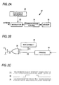
- Figs. 2A to 2C are schematic views of a configuration of an RFID tag (Radio Frequency Identification Tag) 20
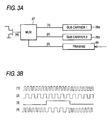
- Figs. 3A and 3B are schematic views of a configuration of reader/writer 10.
- the range measuring system 1 is composed of a reader/writer 10 and an RFID tag 20.
- the RFID tag 20 is provided with a sub carrier generation portion 22, a modulation portion 23, a communications controller 24 and a memory portion 25 in addition to an antenna 21 as shown in Fig. 2A .
- the antenna 21 communicates with the reader/writer 10 in a non-contacted state.
- the antenna may be composed of an appropriate antenna such as a UHF antenna or a loop antenna.
- the sub carrier generation portion 22 generates a sub carrier (sub carrier wave) whose frequency is different from the first frequency (frequency fc) used by the reader/writer 10 as a carrier wave.
- a sub carrier sub carrier wave
- PSK phase shift keying
- FSK frequency shift keying
- a lower frequency than the first frequency is adopted for the sub carrier.
- the memory portion 25 stores ID being identification information of the RFID tag 20 and other data.
- the communications controller 24 carries out communications control by which it receives a command from the reader/writer 10, modulates digital data in the memory portion 25 and responds to the reader/writer 10.
- the communications controller 24 is composed of digital circuits (logic) to execute parallel processing such as sub carrier generation.
- the modulation portion 23 modulates the sub carrier based on digital data transmitted from the communications controller 24. It is composed so that the modulation is selectively carried out based on two types of PSK and FSK.
- the calculator 26 obtains an exclusive logic sum (XOR: exclusive or) of the sub carrier 28 (sub carrier wave shown at [1] in Fig. 2C ) and digital data (data shown at [2] in Fig. 2C ) that is framed by adding a preamble and CRC (Cyclic Redundancy Check), etc., in a framing portion 29, and an after-calculated signal (signal shown at [3] in Fig. 2C ) is generated.
- reflected signals of the first frequency fc which are from the reader/writer 10
- the antenna 21 become a response to the reader/writer 10.
- output signals are generated by changing a sub carrier 28a and a sub carrier 28b by a multiplexer 27 (MUX) using the sub carrier 28a (sub carrier wave shown at [1] in Fig. 3B ), sub carrier 28b (sub carrier wave shown at [2] in Fig. 3B ) and digital data (data shown at [3] in Fig. 3B ) framed by adding a preamble and a CRC thereto at the framing portion 29. And, the signals are sent back from the antenna 21 to the reader/writer 10.
- MUX multiplexer 27
- the RFID tag 20 is provided with a demodulator and a decoder (illustration of which is omitted).
- the demodulator demodulates signals received by the antenna 21 and acquires command signals transmitted from the reader/writer 10.
- the decoder decodes demodulated command signals, and takes out coded command data, wherein processes of reading (transmitting a designated area of the memory portion 25) and writing (writing data following the command in the designated area of the memory portion 25) are carried out.
- the RFID tag 20 there are two types, one of which is a passive type that does not have any power source and responds to actuation by an electric field or magnetic field and the other of which is a semi-passive type that internally includes a power source and responds when receiving a response request from the reader/writer 10. Therefore, the RFID tag 20 can synchronize with carrier waves transmitted from the reader/writer 10.
- the reader/writer 10 is provided with the antenna 11, and is also provided with a controller and a memory portion, illustration of which is omitted.
- the memory portion stores various types of data and also stores a range measuring program to measure the range.
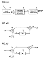
- the reader/writer 10 includes a range calculating portion 13, a frequency component separating portion 14 and a frequency converting portion 15 as shown in Fig. 4A .
- the frequency converting portion 15 carries out frequency conversion in regard to signals received from the antenna 11, and sends the frequency component ( ⁇ fs) of a sub carrier to the frequency component separating portion 14.
- the frequency component separating portion 14 separates the received frequency component ( ⁇ fs) into USB and LSB.
- the LSB can be picked up by the configuration shown in Fig 4B . That is, first, I components and Q components are extracted from input frequencies by means of an orthogonal mixer 14a, wherein the phase of the Q components is changed by +90° by a phase converter 14b. And, the after-phase changed Q component and I components for which the phase has not been changed are synthesized by a synthesizer 14c, thereby extracting the LSB.
- USB can be picked up by the configuration shown in Fig. 4C . That is, first, I components and Q components are extracted from input frequencies by an orthogonal mixer 14a, wherein the phase of the Q components is changed by -90° by a phase converter 14d. And, the after-phase changed Q component and I components for which the phase has not been changed are synthesized by a synthesizer 14c, thereby extracting the USB.
- the range calculating portion 13 shown in Fig. 4A calculates the range using the USB and LSB that are extracted by the frequency component separating portion 14.
- the range calculation is carried out as follows. First, where it is assumed that the phase of the signal of the first frequency fc transmitted by the reader/writer 10 is the reference phase, the signals of the first frequency fc reach the RFID tag 20 located at a distance r from the reader/writer 10 and is reflected therefrom, and phase of carrier waves returned to the reader/writer 10 becomes ⁇ t.
- phase ⁇ ru of the USB signal which is generated by modulation with respect to the signal of the first frequency fc at the RFID tag 20 and has reached the reader/writer 10
- phase ⁇ rl of the LSB signal for the reference phase may be expressed by the following expression.
- Figs. 5A to 5C are schematic views describing a carrier wave, a response signal, USB and LSB where PSK is used.
- an inquiry signal (carrier wave) transmitted by the reader/writer 10 is a signal of the first frequency fc.
- the response signal (reflected wave) responded by the RFID tag 20 is a signal obtained by synthesizing the first frequency fc and the second frequency fs.
- data are expressed in the PSK system.
- the response signal can pick up USB and LSB by separation of frequency components.
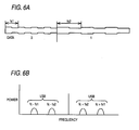
- Figs. 6A and 6B are schematic views describing a carrier wave, a response signal, USB and LSB where FSK is used.
- a response signal (reflected wave) that the RFID tag 20 responds to is a signal obtained by synthesizing the first frequency fc and the second frequency fs and the third frequency fs2, which are sub carriers.
- data are expressed in the FSK system.
- the response signal may obtain a number of components separated into USB and LSB and separated into the second frequency fs1 component and the third frequency fs2 component by separation of frequency components.
- three or more frequency components may be used, wherein a high-resolution power algorithm based on the MUSIC (Multiple Signal Classification) method disclosed by the International Publication WO2006/095463 , etc., may be used. Accordingly, the accuracy under multi-pass environments can be improved with transmission frequency from the reader/writer 10 remaining as one frequency.
- MUSIC Multiple Signal Classification
- Fig. 7 is a flowchart showing actions when a range from the reader/writer 10 to the RFID tag 20 is obtained by the range measuring system 1.
- the reader/writer 10 carries out command transmission and requests a response for ID from the RFID tag 20 (Step S1).
- the command is transmitted by the first frequency fc.
- the command includes a modulation system code to determine whether the modulation system is based on PSK or FSK.
- the RFID tag 20 analyzes the command from the reader/writer 10 (Step S2) and extracts the modulation system code.
- Step S4 PSK
- the RFID tag 20 changes the modulation portion 23 to the PSK circuit (Step S5). If the modulation system is based on the FSK (Step S4: FSK), the RFID tag 20 changes the modulation portion 23 to the FSK circuit (Step S6).
- the RFID tag 20 reads memory data stored in the memory 25 (this example includes ID) (Step S7), and frames by adding a preamble and CRC thereto (Step S8).
- the RFID tag 20 modulates framed data by the system (PSK or FSK) changed by Steps S4 through S6 (Step S9), and sends back a response signal (Response) (Step S10).
- the reader/writer 10 receives a response signal (Response) (Step S11), and detects whether or not there is any error, by a CRC check (redundancy cyclic inspection) (Step S12).
- Step S12 If any error occurs (Step S12: NG), the reader/writer 10 returns the process to Step S1, and carries out the process again. If there is no error (Step S12: OK), the reader/writer 10 carries out a process of FFT (Fast Fourier Transform) of the received signal by the frequency converting portion 15 (Step S13).
- FFT Fast Fourier Transform
- the reader/writer 10 further separates LSB and USB from each other by the frequency component separating portion 14 (Step S14), calculates a phase by the range calculating portion 13 (Step S15), and carries out estimation of the range based on the phase difference (Step S16).
- the reader/writer 10 combines the calculated range with an ID included in the signals received in Step S11 and outputs the same (Step S17), and then terminates the process. Also, the output may be carried out by an appropriate method such as storing the output in a memory unit of the reader/writer 10, transmitting the same to another device connected to the reader/writer 10 or displaying the same in a display device secured at the reader/writer 10.
- the reader/writer 10 receives a response signal including multiple frequency components from the RFID tag 20, and can calculate the range from the reader/writer 10 to the RFID tag 20.
- the RFID tag 20 returns reflected waves (response signals) with respect to a single frequency transmitted from the reader/writer 10, using frequency components, wherein the measurement accuracy can be improved by using multiple frequencies.
- PSK and FSK are used, the frequency separation is not limited thereto, but various methods may be used to separate frequencies to enable range measurement.
- the modulating portion 23 of the RFID tag 20 carries out modulation in the PSK system.
- the reader/writer 10 extracts high frequency components (odd-number order such as primary, tertiary, quinary, etc.) as shown in Fig. 8 , and these high frequency components may be used.
- high frequency components odd-number order such as primary, tertiary, quinary, etc.
- a high-resolution power algorithm based on the MUSIC method may be utilized. Therefore, the accuracy under a multiple-pass environment can be improved with the transmission frequency from the reader/writer 10 remaining as one frequency.
- the RFID tag 20 is of a semi-passive type having a power source. Accordingly, power necessary to pick up high frequencies can be secured, and can be effectively utilized.
- the frequency component separating portion 14 uses a complex FFT operation.
- received signals are separated into I signals and Q signals by the orthogonal mixer 14a, and the respective signals may be separated into real parts and imaginary parts by complex FFT operations 14e and 14f.
- USB components and LSB components for which addition and subtraction are further carried out are extracted, and phases of USB and LSB may be calculated from the respective I components and Q components.
- the reader/writer 10 receives a response signal from the RFID tag 20 corresponding thereto, and can calculate the range from the reader/writer 10 to the RFID tag 20.
- the RFID tag 20 may be composed so as to function as a sensing device.
- the RFID tag 20 may be equipped with an appropriate sensor such as a temperature sensor, a humidity sensor, etc., instead of the memory portion 25 or connecting thereto.
- the RFID tag 20 frames a measurement value of the corresponding sensor as data, modulates the same and responds to the reader/writer. Therefore, the reader/writer 10 can acquire sensing information in a non-contacted state, and is able to recognize by range calculation at which position (range) the sensing information has been obtained.
- the composition of the invention matches or corresponds to the above-described embodiment as shown below;
- the range measuring system according to the invention matches or corresponds to a range measuring system 1 according to the embodiment.
- the reader unit and range measuring apparatus match or correspond to the reader/writer 10
- the communication unit matches or corresponds to the antenna 11
- the range measuring unit matches or corresponds to the range calculating portion 13
- the frequency component acquiring unit matches or corresponds to the frequency component separating portion 14
- the non-contacted IC medium matches or corresponds to the RFID tag 20
- the communications unit matches or corresponds to the antenna 21
- the modulating unit matches or corresponds to the modulating portion 23
- the inquiry process matches or corresponds to Step S1
- the inquiry signal receiving process matches or corresponds to Step S2
- the response signal receiving process matches or corresponds to Step S11
- the frequency component acquiring process matches or corresponds to Steps S13 and S14
- the range measuring process matches or corresponds to Steps S15 and S16.
- the invention is not limited to only the composition
- a range measuring method it is possible to provide a range measuring method, a range measuring apparatus, a non-contacted IC medium, a range measuring system and a range measuring program, which are capable of executing highly accurate range measurements even if the non-contacted IC medium is in motion.
Landscapes
- Engineering & Computer Science (AREA)
- Radar, Positioning & Navigation (AREA)
- Remote Sensing (AREA)
- Computer Networks & Wireless Communication (AREA)
- Physics & Mathematics (AREA)
- General Physics & Mathematics (AREA)
- Near-Field Transmission Systems (AREA)
- Radar Systems Or Details Thereof (AREA)
Abstract
Description
- The present invention relates to a range measuring method, a range measuring apparatus, a non-contacted IC medium, a range measuring system and a range measuring program, which measures a range, for example, from a reader unit to a non-contacted IC medium.
- There is a range measuring apparatus that measures the range to a non-contacted IC medium using multiple frequencies (refer to International Publication
WO 2006/095463 ). The range measuring apparatus controls an RFID tag (non-contacted IC medium) to transmit two times a R/W request signal that requests transmission of a tag response signal. At this time, a frequency controller controls a PLL portion to transmit respective R/W request signals by transfer frequencies differing from each other. A phase information acquisition portion detects fluctuation amounts in phase of tag response signals transmitted by the transfer frequencies differing from each other, respectively, and calculates the range between a reader/writer and the RFID tag based on the fluctuation amounts in the phase. Therefore, the range between the reader/writer and the RFID tag can be accurately calculated. - However, it cannot be necessarily said that the non-contacted IC medium always stops at a fixed position. And, there is a case where the range to a non-contacted IC medium in motion is requested to be obtained. In such a case, since the above-described range measuring apparatus carries out transmission and receiving of different frequencies at different timings, a deviation occurs at the receiving timing. Therefore, where the non-contacted IC medium is conveyed at a high speed, it is difficult to accurately calculate the range.
- It is therefore a Preferred aim of the invention to provide a range measuring method, a range measuring apparatus, a non-contacted IC medium, a range measuring system and a range measuring program, which are capable of carrying out highly accurate range measurements even if a non-contacted IC medium is in motion.
- According to the invention, there is provided a method of measuring a range from a reader unit to a non-contacted IC medium, the method comprising: transmitting an inquiry signal at a first frequency from the reader unit to the non-contacted IC medium; causing the non-contacted IC medium to perform modulation to modulate the first frequency by using a second frequency to obtain a modulated frequency, and causing the non-contacted IC medium to respond to a response signal at the modulated frequency; causing the reader unit to receive the response signal to acquire a plurality of frequency components; calculating a phase difference between signals of at least two of the acquired plurality of frequency components; and measuring the range by using the phase difference.
- Phase shift keying may be used for the modulation.
- Frequency shift keying may be used for the modulation.
- The modulation may be digital modulation, and the plurality of frequency components may be high frequency components generated in the digital modulation.
- The response signal may be separated into an upper side band and a lower side band in order to acquire the plurality of frequency components.
- According to the invention, there is also provided an apparatus, operable to measure a range from a reader unit to a non-contacted IC medium, the apparatus comprising: a communication unit, transmitting an inquiry signal at a first frequency from the reader unit to the non-contacted IC medium, and receiving a response signal from the non-contacted IC medium; a frequency component acquiring unit, acquiring a plurality of frequency components from the response signal; and a range measuring unit, calculating a phase difference between signals of at least two of the acquired plurality of frequency components, and measuring the range by using the phase difference.
- According to the invention, there is also provided a non-contact IC medium, comprising: a communication unit, receiving an inquiry signal at a first frequency from a reader unit, and responding to a response signal to the reader unit; and a modulation unit, performing modulation to modulate the first frequency by using a second frequency to obtain a modulated frequency, wherein the communication unit responds to the response signal at the modulated frequency.
- According to the invention, there is also provided a range measuring system, comprising: a non-contacted IC medium; and a range measuring apparatus, operable to measure a range from a reader unit to the non-contacted IC medium, the apparatus comprising: a first communication unit, transmitting an inquiry signal at a first frequency from the reader unit to the non-contacted IC medium, and receiving a response signal from the non-contacted IC medium; a frequency component acquiring unit, acquiring a plurality of frequency components from the response signal; and a range measuring unit, calculating a phase difference between signals of at least two of the acquired plurality of frequency components, and measuring the range by using the phase difference, wherein the non-contacted IC medium comprises: a second communication unit, receiving the inquiry signal at the first frequency from the reader unit, and responding to the response signal to the reader unit; and a modulation unit, performing modulation to modulate the first frequency by using a second frequency to obtain a modulated frequency, and the second communication unit responds to the response signal at the modulated frequency.
- According to the invention, there is also provided a range measuring program for causing a reader unit, which includes a communication unit communicating with a non-contacted IC medium and a control unit carrying out various types of control, to execute: an inquiry process for transmitting an inquiry signal to the non-contacted IC medium at the first frequency by the communication unit; a response signal receiving process for receiving a response signal from the non-contacted IC medium; a frequency component acquiring process for acquiring a plurality of frequency components from the received response signal; and a range measuring process for calculating a phase difference between signals of at least two of the acquired plurality of frequency components and measuring a range from the reader unit to the non-contacted IC medium by using the phase difference.
- The inquiry signal may be made into a signal for which the reader unit causes the non-contacted IC medium to respond, and for example, may be made into a signal including a command to send an ID.
The response signal may be made into a signal for which the non-contacted IC medium responds to the reader unit, and for example, may be made into a signal to send an ID. - The upper side band may be made into a USB (Upper Side Band), and the lower side band may be made into an LSB (Lower Side Band).
- The frequency component acquiring unit may be a unit for acquiring, for example, frequency components while separating the same into USB components and LSB components, and may be composed as a unit for acquiring frequencies with the same separated as per component.
- The range measuring unit may be composed of a unit for measuring a range by per-component frequencies, and may be composed of a unit for calculating appropriately using numerical expressions.
The range measuring apparatus may be made into a reader unit that can communicate with a non-contacted IC medium. - The inquiry process may be made into a process for transmitting an inquiry signal to inquire about an ID, etc., to a non-contacted IC medium.
The response signal receiving process may be made into a process for receiving a response signal from the non-contacted IC medium. - The frequency component acquiring process may be composed of a process for separating a response signal into components of different frequencies.
The range measuring process may be composed of a process for measuring a range by calculation expressions. -
-
Fig. 1 is a system configuration view of a range measuring system. -
Figs. 2A, 2B and 2C are schematic views describing a configuration of an RFID tag. -
Figs. 3A and 3B are schematic views describing a configuration of a reader/writer. -
Figs. 4A, 4B and 4C are schematic views describing a detailed configuration of a reader/writer. -
Figs. 5A, 5B and 5C are schematic views describing a PSK system. -
Figs. 6A and 6B are schematic views describing an FSK system. -
Fig. 7 is a flowchart showing actions of the range measuring system. -
Fig. 8 is a schematic view describing a system utilizing high frequency components. -
Fig. 9 is a configurational view of a frequency component separating portion that carries out complex FFT operations. - A description is given of one embodiment of the invention with reference to the following drawings.
Fig. 1 is a configuration view of arange measuring system 1,Figs. 2A to 2C are schematic views of a configuration of an RFID tag (Radio Frequency Identification Tag) 20, andFigs. 3A and 3B are schematic views of a configuration of reader/writer 10.
Therange measuring system 1 is composed of a reader/writer 10 and anRFID tag 20. - The
RFID tag 20 is provided with a subcarrier generation portion 22, amodulation portion 23, acommunications controller 24 and amemory portion 25 in addition to anantenna 21 as shown inFig. 2A . - The
antenna 21 communicates with the reader/writer 10 in a non-contacted state. The antenna may be composed of an appropriate antenna such as a UHF antenna or a loop antenna. - The sub
carrier generation portion 22 generates a sub carrier (sub carrier wave) whose frequency is different from the first frequency (frequency fc) used by the reader/writer 10 as a carrier wave. In the embodiment, phase shift keying (PSK) or frequency shift keying (FSK) may be selectively used as the modulation system of the sub carrier. Also, a lower frequency than the first frequency is adopted for the sub carrier. - The
memory portion 25 stores ID being identification information of theRFID tag 20 and other data.
Thecommunications controller 24 carries out communications control by which it receives a command from the reader/writer 10, modulates digital data in thememory portion 25 and responds to the reader/writer 10. Thecommunications controller 24 is composed of digital circuits (logic) to execute parallel processing such as sub carrier generation. - The
modulation portion 23 modulates the sub carrier based on digital data transmitted from thecommunications controller 24. It is composed so that the modulation is selectively carried out based on two types of PSK and FSK. - First, a detailed description is given of the PSK. As shown in
Fig. 2B , thecalculator 26 obtains an exclusive logic sum (XOR: exclusive or) of the sub carrier 28 (sub carrier wave shown at [1] inFig. 2C ) and digital data (data shown at [2] inFig. 2C ) that is framed by adding a preamble and CRC (Cyclic Redundancy Check), etc., in a framingportion 29, and an after-calculated signal (signal shown at [3] inFig. 2C ) is generated. And, reflected signals of the first frequency fc, which are from the reader/writer 10, by theantenna 21 are controlled by changing the impedance of theantenna 21 based on the signals. The reflected signals by theantenna 21 become a response to the reader/writer 10. - A detailed description is given of FSK. As shown in
Fig. 3A , output signals (signals shown at [4] inFig. 3B ) are generated by changing asub carrier 28a and asub carrier 28b by a multiplexer 27 (MUX) using thesub carrier 28a (sub carrier wave shown at [1] inFig. 3B ),sub carrier 28b (sub carrier wave shown at [2] inFig. 3B ) and digital data (data shown at [3] inFig. 3B ) framed by adding a preamble and a CRC thereto at the framingportion 29. And, the signals are sent back from theantenna 21 to the reader/writer 10. - Also, the
RFID tag 20 is provided with a demodulator and a decoder (illustration of which is omitted). The demodulator demodulates signals received by theantenna 21 and acquires command signals transmitted from the reader/writer 10. The decoder decodes demodulated command signals, and takes out coded command data, wherein processes of reading (transmitting a designated area of the memory portion 25) and writing (writing data following the command in the designated area of the memory portion 25) are carried out. - In addition, for the
RFID tag 20, there are two types, one of which is a passive type that does not have any power source and responds to actuation by an electric field or magnetic field and the other of which is a semi-passive type that internally includes a power source and responds when receiving a response request from the reader/writer 10. Therefore, theRFID tag 20 can synchronize with carrier waves transmitted from the reader/writer 10. - The reader/
writer 10 is provided with theantenna 11, and is also provided with a controller and a memory portion, illustration of which is omitted. The memory portion stores various types of data and also stores a range measuring program to measure the range. In addition, the reader/writer 10 includes arange calculating portion 13, a frequencycomponent separating portion 14 and afrequency converting portion 15 as shown inFig. 4A . - The
frequency converting portion 15 carries out frequency conversion in regard to signals received from theantenna 11, and sends the frequency component (±fs) of a sub carrier to the frequencycomponent separating portion 14.
The frequencycomponent separating portion 14 separates the received frequency component (±fs) into USB and LSB. - Herein, the LSB can be picked up by the configuration shown in
Fig 4B . That is, first, I components and Q components are extracted from input frequencies by means of anorthogonal mixer 14a, wherein the phase of the Q components is changed by +90° by aphase converter 14b. And, the after-phase changed Q component and I components for which the phase has not been changed are synthesized by asynthesizer 14c, thereby extracting the LSB. - In addition, USB can be picked up by the configuration shown in
Fig. 4C . That is, first, I components and Q components are extracted from input frequencies by anorthogonal mixer 14a, wherein the phase of the Q components is changed by -90° by aphase converter 14d. And, the after-phase changed Q component and I components for which the phase has not been changed are synthesized by asynthesizer 14c, thereby extracting the USB. - The
range calculating portion 13 shown inFig. 4A calculates the range using the USB and LSB that are extracted by the frequencycomponent separating portion 14. The range calculation is carried out as follows.
First, where it is assumed that the phase of the signal of the first frequency fc transmitted by the reader/writer 10 is the reference phase, the signals of the first frequency fc reach theRFID tag 20 located at a distance r from the reader/writer 10 and is reflected therefrom, and phase of carrier waves returned to the reader/writer 10 becomes Φt. And, the phase Φru of the USB signal, which is generated by modulation with respect to the signal of the first frequency fc at theRFID tag 20 and has reached the reader/writer 10, for the reference phase and the phase Φrl of the LSB signal for the reference phase may be expressed by the following expression.


Therefore, the range from the reader/writer 10 to theRFID tag 20 may be calculated by the following expression.
-

-
Figs. 5A to 5C are schematic views describing a carrier wave, a response signal, USB and LSB where PSK is used.
As shown inFig. 5A , an inquiry signal (carrier wave) transmitted by the reader/writer 10 is a signal of the first frequency fc. - As shown in
Fig. 5B , the response signal (reflected wave) responded by theRFID tag 20 is a signal obtained by synthesizing the first frequency fc and the second frequency fs. For the response signal, data are expressed in the PSK system. - As shown in
Fig. 5C , the response signal can pick up USB and LSB by separation of frequency components.
Figs. 6A and 6B are schematic views describing a carrier wave, a response signal, USB and LSB where FSK is used.
As shown inFig. 6A , a response signal (reflected wave) that theRFID tag 20 responds to is a signal obtained by synthesizing the first frequency fc and the second frequency fs and the third frequency fs2, which are sub carriers. For the response signal, data are expressed in the FSK system. - As shown in
Fig. 6B , the response signal may obtain a number of components separated into USB and LSB and separated into the second frequency fs1 component and the third frequency fs2 component by separation of frequency components. In this case, three or more frequency components may be used, wherein a high-resolution power algorithm based on the MUSIC (Multiple Signal Classification) method disclosed by the International PublicationWO2006/095463 , etc., may be used. Accordingly, the accuracy under multi-pass environments can be improved with transmission frequency from the reader/writer 10 remaining as one frequency. -
Fig. 7 is a flowchart showing actions when a range from the reader/writer 10 to theRFID tag 20 is obtained by therange measuring system 1.
First, the reader/writer 10 carries out command transmission and requests a response for ID from the RFID tag 20 (Step S1). At this time, the command is transmitted by the first frequency fc. Also, the command includes a modulation system code to determine whether the modulation system is based on PSK or FSK. - The
RFID tag 20 analyzes the command from the reader/writer 10 (Step S2) and extracts the modulation system code. - If the modulation system is based on the PSK (Step S4: PSK), the
RFID tag 20 changes themodulation portion 23 to the PSK circuit (Step S5).
If the modulation system is based on the FSK (Step S4: FSK), theRFID tag 20 changes themodulation portion 23 to the FSK circuit (Step S6). - The
RFID tag 20 reads memory data stored in the memory 25 (this example includes ID) (Step S7), and frames by adding a preamble and CRC thereto (Step S8). - The
RFID tag 20 modulates framed data by the system (PSK or FSK) changed by Steps S4 through S6 (Step S9), and sends back a response signal (Response) (Step S10). - The reader/
writer 10 receives a response signal (Response) (Step S11), and detects whether or not there is any error, by a CRC check (redundancy cyclic inspection) (Step S12). - If any error occurs (Step S12: NG), the reader/
writer 10 returns the process to Step S1, and carries out the process again.
If there is no error (Step S12: OK), the reader/writer 10 carries out a process of FFT (Fast Fourier Transform) of the received signal by the frequency converting portion 15 (Step S13). - The reader/
writer 10 further separates LSB and USB from each other by the frequency component separating portion 14 (Step S14), calculates a phase by the range calculating portion 13 (Step S15), and carries out estimation of the range based on the phase difference (Step S16). - The reader/
writer 10 combines the calculated range with an ID included in the signals received in Step S11 and outputs the same (Step S17), and then terminates the process. Also, the output may be carried out by an appropriate method such as storing the output in a memory unit of the reader/writer 10, transmitting the same to another device connected to the reader/writer 10 or displaying the same in a display device secured at the reader/writer 10. - Based on the above-described configuration and actions, only by an inquiry signal being transmitted one time at a single frequency from the reader/
writer 10, the reader/writer 10 receives a response signal including multiple frequency components from theRFID tag 20, and can calculate the range from the reader/writer 10 to theRFID tag 20. - Therefore, even if the
RFID tag 20, which is the object for range measurement, is moving at a high speed, it is possible to carry out highly accurate range measurements. That is, where a plurality of frequencies are transmitted from the reader/writer 10 one after another, if theRFID tag 20 is moving, accurate range measurements become difficult if the positions of theRFID tag 20 differ from each other when transmitting respective frequencies. However, in the above-described embodiment, since an inquiry signal is transmitted one time at a single frequency, no time lag occurs, wherein accurate range measurements are enabled. - Also, since calculation is carried out by obtaining a phase difference of a sub carrier (the second frequency), it is possible to accurately measure the range by canceling the reflected wave.
- In addition, since the frequency transmitted by the reader/
writer 10 is regulated by the radio wave law, it was difficult to change the frequency of transmission waves as in the prior art. However, since the frequency of reflected waves from theRFID tag 20 is not regulated, range measurement can be carried out by frequency separation using frequencies for which differences are sufficiently widened based on the above reason. - Where the PSK is used, a range can be simply measured.
- Also, where the FSK is used, the
RFID tag 20 returns reflected waves (response signals) with respect to a single frequency transmitted from the reader/writer 10, using frequency components, wherein the measurement accuracy can be improved by using multiple frequencies. - In addition, since the upper side band (USB) and the lower side band (LSB) are separated from each other, noise in the reflected waves can be separated, wherein highly accurate range measurement can be achieved.
- Further, in the above-described embodiment, although PSK and FSK are used, the frequency separation is not limited thereto, but various methods may be used to separate frequencies to enable range measurement.
- For example, the modulating
portion 23 of theRFID tag 20 carries out modulation in the PSK system. The reader/writer 10 extracts high frequency components (odd-number order such as primary, tertiary, quinary, etc.) as shown inFig. 8 , and these high frequency components may be used. In this case, since three or more frequency components may be used, a high-resolution power algorithm based on the MUSIC method may be utilized. Therefore, the accuracy under a multiple-pass environment can be improved with the transmission frequency from the reader/writer 10 remaining as one frequency.
Furthermore, where such high frequency components are used, it is preferable that theRFID tag 20 is of a semi-passive type having a power source. Accordingly, power necessary to pick up high frequencies can be secured, and can be effectively utilized. - Also, as shown in
Fig. 9 , it may be composed that the frequencycomponent separating portion 14 uses a complex FFT operation. In this case, received signals are separated into I signals and Q signals by theorthogonal mixer 14a, and the respective signals may be separated into real parts and imaginary parts bycomplex FFT operations
In this case, the respective phases of USB and LSB may be obtained by the following mathematical expressions.
- * FFT (I)Re: Real part separated from I signals by complex FFT operation
FFT(I)Im: Imaginary part separated from I signals by complex FFT operation
FFT(Q)Re: Real part separated from Q signals by complex FFT operation
FFT(Q)Im: Imaginary part separated from Q signals by complex FFT operation
Arctan(X): Function for calculation of arc-tangent of X
- * FFT(I)Re: Real part separated from I signals by complex FFT operation
FFT(I)Im: Imaginary part separated from I signals by complex FFT operation
FFT(Q)Re: Real part separated from Q signals by complex FFT operation
FFT(Q)Im: Imaginary part separated from Q signals by complex FFT operation
Arctan(X): Function for calculation of arc-tangent of X - In this case, only by an inquiry signal being transmitted from the reader/
writer 10 one time at a single frequency, the reader/writer 10 receives a response signal from theRFID tag 20 corresponding thereto, and can calculate the range from the reader/writer 10 to theRFID tag 20. - In addition, the
RFID tag 20 may be composed so as to function as a sensing device. In this case, theRFID tag 20 may be equipped with an appropriate sensor such as a temperature sensor, a humidity sensor, etc., instead of thememory portion 25 or connecting thereto. And, it may be composed that theRFID tag 20 frames a measurement value of the corresponding sensor as data, modulates the same and responds to the reader/writer.
Therefore, the reader/writer 10 can acquire sensing information in a non-contacted state, and is able to recognize by range calculation at which position (range) the sensing information has been obtained. - The composition of the invention matches or corresponds to the above-described embodiment as shown below;
The range measuring system according to the invention matches or corresponds to arange measuring system 1 according to the embodiment.
Similarly, the reader unit and range measuring apparatus match or correspond to the reader/writer 10,
the communication unit matches or corresponds to theantenna 11,
the range measuring unit matches or corresponds to therange calculating portion 13,
the frequency component acquiring unit matches or corresponds to the frequencycomponent separating portion 14,
the non-contacted IC medium matches or corresponds to theRFID tag 20,
the communications unit matches or corresponds to theantenna 21,
the modulating unit matches or corresponds to the modulatingportion 23,
the inquiry process matches or corresponds to Step S1,
the inquiry signal receiving process matches or corresponds to Step S2,
the response signal receiving process matches or corresponds to Step S11,
the frequency component acquiring process matches or corresponds to Steps S13 and S14, and
the range measuring process matches or corresponds to Steps S15 and S16.
However, the invention is not limited to only the composition of the above-described embodiment, but may be subjected to various embodiments. - According to an aspect of the invention, it is possible to provide a range measuring method, a range measuring apparatus, a non-contacted IC medium, a range measuring system and a range measuring program, which are capable of executing highly accurate range measurements even if the non-contacted IC medium is in motion.


Claims (9)
- A method of measuring a range from a reader unit to a non-contacted IC medium, the method comprising:transmitting an inquiry signal at a first frequency from the reader unit to the non-contacted IC medium;causing the non-contacted IC medium to perform modulation to modulate the first frequency by using a second frequency to obtain a modulated frequency, and causing the non-contacted IC medium to respond to a response signal at the modulated frequency;causing the reader unit to receive the response signal to acquire a plurality of frequency components;calculating a phase difference between signals of at least two of the acquired plurality of frequency components; andmeasuring the range by using the phase difference.
- The method according to claim 1, wherein phase shift keying is used for the modulation.
- The method according to claim 1, wherein frequency shift keying is used for the modulation.
- The method according to any one of claims 1, 2 and 3,
wherein
the modulation is digital modulation, and
the plurality of frequency components are high frequency components generated in the digital modulation. - The method according to any one of claims 1 through 4, wherein the response signal is separated into an upper side band and a lower side band in order to acquire the plurality of frequency components.
- An apparatus, operable to measure a range from a reader unit to a non-contacted IC medium, the apparatus comprising:a communication unit, transmitting an inquiry signal at a first frequency from the reader unit to the non-contacted IC medium, and receiving a response signal from the non-contacted IC medium;a frequency component acquiring unit, acquiring a plurality of frequency components from the response signal; anda range measuring unit, calculating a phase difference between signals of at least two of the acquired plurality of frequency components, and measuring the range by using the phase difference.
- A non-contact IC medium, comprising:a communication unit, receiving an inquiry signal at a first frequency from a reader unit, and responding to a response signal to the reader unit; anda modulation unit, performing modulation to modulate the first frequency by using a second frequency to obtain a modulated frequency,wherein the communication unit responds to the response signal at the modulated frequency.
- A range measuring system, comprising:a non-contacted IC medium; anda range measuring apparatus, operable to measure a range from a reader unit to the non-contacted IC medium, the apparatus comprising:a first communication unit, transmitting an inquiry signal at a first frequency from the reader unit to the non-contacted IC medium, and receiving a response signal from the non-contacted IC medium;a frequency component acquiring unit, acquiring a plurality of frequency components from the response signal; anda range measuring unit, calculating a phase difference between signals of at least two of the acquired plurality of frequency components, and measuring the range by using the phase difference, wherein the non-contacted IC medium comprises: a second communication unit, receiving the inquiry signal at the first frequency from the reader unit, and responding to the response signal to the reader unit; and a modulation unit, performing modulation to modulate the first frequency by using a second frequency to obtain a modulated frequency, andthe second communication unit responds to the response signal at the modulated frequency.
- A range measuring program for causing a reader unit, which includes a communication unit communicating with a non-contacted IC medium and a control unit carrying out various types of control, to execute:an inquiry process for transmitting an inquiry signal to the non-contacted IC medium at the first frequency by the communication unit;a response signal receiving process for receiving a response signal from the non-contacted IC medium;a frequency component acquiring process for acquiring a plurality of frequency components from the received response signal; anda range measuring process for calculating a phase difference between signals of at least two of the acquired plurality of frequency components and measuring a range from the reader unit to the non-contacted IC medium by using the phase difference.
Applications Claiming Priority (1)
| Application Number | Priority Date | Filing Date | Title |
|---|---|---|---|
| JP2007325887A JP2009145300A (en) | 2007-12-18 | 2007-12-18 | Distance measuring method, distance measuring device, non-contact IC medium, distance measuring system, and distance measuring program |
Publications (2)
| Publication Number | Publication Date |
|---|---|
| EP2073036A1 true EP2073036A1 (en) | 2009-06-24 |
| EP2073036B1 EP2073036B1 (en) | 2012-06-13 |
Family
ID=40513814
Family Applications (1)
| Application Number | Title | Priority Date | Filing Date |
|---|---|---|---|
| EP08254035A Active EP2073036B1 (en) | 2007-12-18 | 2008-12-17 | Range measuring method, range measuring apparatus, range measuring system and range measuring program |
Country Status (4)
| Country | Link |
|---|---|
| US (1) | US8149155B2 (en) |
| EP (1) | EP2073036B1 (en) |
| JP (1) | JP2009145300A (en) |
| CN (1) | CN101464517A (en) |
Cited By (3)
| Publication number | Priority date | Publication date | Assignee | Title |
|---|---|---|---|---|
| EP2407799A1 (en) * | 2010-07-16 | 2012-01-18 | Sivers Ima AB | Method and device for continuous wave radar measurements |
| EP2873168A4 (en) * | 2012-07-11 | 2016-03-02 | Tag Comm Inc | TRANSMISSION APPARATUS FOR A WIRELESS DEVICE |
| US10079704B2 (en) | 2014-09-22 | 2018-09-18 | Drnc Holdings, Inc. | Transmission apparatus for a wireless device using delta-sigma modulation |
Families Citing this family (11)
| Publication number | Priority date | Publication date | Assignee | Title |
|---|---|---|---|---|
| GB0709313D0 (en) * | 2007-05-15 | 2007-06-20 | Siemens Ag | RFID reader |
| WO2011054128A1 (en) * | 2009-11-03 | 2011-05-12 | 北京简约纳电子有限公司 | Device and method for precisely measuring near-field communication distance of radio frequency identification (rfid) tag |
| US8823577B2 (en) * | 2009-12-23 | 2014-09-02 | Itrack, Llc | Distance separation tracking system |
| JP5887539B2 (en) * | 2010-09-14 | 2016-03-16 | パナソニックIpマネジメント株式会社 | Radar equipment |
| US9911018B1 (en) | 2012-01-12 | 2018-03-06 | Impinj, Inc. | RFID tags with digital signature subportions |
| US11361174B1 (en) | 2011-01-17 | 2022-06-14 | Impinj, Inc. | Enhanced RFID tag authentication |
| US8723720B2 (en) * | 2011-05-03 | 2014-05-13 | Harris Corporation | Wireless location detection and/or tracking device and associated methods |
| CN102957453B (en) * | 2011-08-25 | 2016-03-30 | 国民技术股份有限公司 | A kind of communication means of the radio-frequency SIM card based on magnetic communication and system |
| JP7119369B2 (en) * | 2017-12-21 | 2022-08-17 | 株式会社アイシン | Distance measuring device |
| US11175402B2 (en) * | 2019-11-25 | 2021-11-16 | Texas Instruments Incorporated | Time-varying template for improved short-distance performance in coded ultrasonic ranging |
| JP7029147B2 (en) * | 2020-12-25 | 2022-03-03 | 株式会社東海理化電機製作所 | Radio wave propagation distance estimation system |
Citations (4)
| Publication number | Priority date | Publication date | Assignee | Title |
|---|---|---|---|---|
| WO1987003698A1 (en) | 1985-12-12 | 1987-06-18 | STIFTELSEN INSTITUTET FÖR MIKROVA^oGSTEKNIK VID | A method and apparatus for measuring distances |
| US20020008615A1 (en) | 1999-11-30 | 2002-01-24 | Patric Heide | Anti-theft protection system for a motor vehicle, and a method for operating an anti-theft protection system |
| EP1225422A1 (en) | 2001-01-19 | 2002-07-24 | COMAU S.p.A. | Process and system for measuring the distance of a moving body from a fixed part |
| EP1863190A1 (en) * | 2005-03-09 | 2007-12-05 | Omron Corporation | Distance measuring apparatus, distance measuring method, reflector and communication system |
Family Cites Families (24)
| Publication number | Priority date | Publication date | Assignee | Title |
|---|---|---|---|---|
| DE1252277B (en) * | 1963-08-19 | |||
| JPS511558B1 (en) * | 1970-12-30 | 1976-01-19 | ||
| JP2516131B2 (en) * | 1992-01-20 | 1996-07-10 | 株式会社ミリウェイブ | Transceiver circuit for ID card system |
| JPH08191259A (en) * | 1995-01-11 | 1996-07-23 | Sony Chem Corp | Transceiver for non-contact type IC card system |
| JP3051647B2 (en) * | 1995-02-21 | 2000-06-12 | 三菱重工業株式会社 | Contactless IC card and system |
| JPH08241383A (en) * | 1995-03-03 | 1996-09-17 | Mitsubishi Electric Corp | Contactless IC card, contactless IC card system including the same, and data transmission method thereof |
| JPH09211114A (en) * | 1996-01-31 | 1997-08-15 | Hitachi Ltd | Moving body position measuring method and apparatus |
| WO2000045328A1 (en) * | 1999-01-26 | 2000-08-03 | Koninklijke Philips Electronics N.V. | Data carrier provided with at least two decoding stages |
| EP1026627A1 (en) * | 1999-01-29 | 2000-08-09 | Siemens Aktiengesellschaft | Contactless data communication system and method |
| JP3572391B2 (en) * | 1999-08-04 | 2004-09-29 | 日産自動車株式会社 | Distance measuring device |
| US7580378B2 (en) | 2000-06-06 | 2009-08-25 | Alien Technology Corporation | Distance/ranging determination using relative phase data |
| US6868073B1 (en) | 2000-06-06 | 2005-03-15 | Battelle Memorial Institute K1-53 | Distance/ranging by determination of RF phase delta |
| FR2831305B1 (en) * | 2001-10-23 | 2004-01-30 | Inside Technologies | CONTACTLESS INTEGRATED CIRCUIT COMPRISING AUTOMATIC FRAME IDENTIFICATION MEANS |
| JP2003207557A (en) * | 2002-01-10 | 2003-07-25 | Mitsubishi Electric Corp | Mobile station and mobile communication system |
| JP2007240534A (en) * | 2003-07-28 | 2007-09-20 | Rcs:Kk | Active tag device |
| JP4254419B2 (en) * | 2003-08-20 | 2009-04-15 | ブラザー工業株式会社 | Interrogator for communication system |
| US7026935B2 (en) * | 2003-11-10 | 2006-04-11 | Impinj, Inc. | Method and apparatus to configure an RFID system to be adaptable to a plurality of environmental conditions |
| US7209071B1 (en) * | 2004-05-07 | 2007-04-24 | Steele Boring | System and method for distance measurement |
| JP4020096B2 (en) | 2004-05-11 | 2007-12-12 | ソニー株式会社 | Wireless communication system, wireless communication apparatus, and wireless communication method |
| JP2006042201A (en) * | 2004-07-29 | 2006-02-09 | Advanced Telecommunication Research Institute International | Distance measuring system, distance measuring method and communication device |
| US7405662B2 (en) * | 2005-06-14 | 2008-07-29 | Datalogic Mobile, Inc. | Wireless tag ranging |
| JP4358836B2 (en) * | 2005-06-17 | 2009-11-04 | 東芝テック株式会社 | Direct conversion radio |
| EP1920571B1 (en) * | 2005-08-11 | 2013-01-23 | Semiconductor Energy Laboratory Co., Ltd. | Semiconductor device and wireless communication system |
| JP2007155554A (en) * | 2005-12-06 | 2007-06-21 | Fujitsu Ltd | Position detection device for detecting the position of an RFID tag |
-
2007
- 2007-12-18 JP JP2007325887A patent/JP2009145300A/en active Pending
-
2008
- 2008-12-17 EP EP08254035A patent/EP2073036B1/en active Active
- 2008-12-18 US US12/338,538 patent/US8149155B2/en active Active
- 2008-12-18 CN CNA2008101859695A patent/CN101464517A/en active Pending
Patent Citations (4)
| Publication number | Priority date | Publication date | Assignee | Title |
|---|---|---|---|---|
| WO1987003698A1 (en) | 1985-12-12 | 1987-06-18 | STIFTELSEN INSTITUTET FÖR MIKROVA^oGSTEKNIK VID | A method and apparatus for measuring distances |
| US20020008615A1 (en) | 1999-11-30 | 2002-01-24 | Patric Heide | Anti-theft protection system for a motor vehicle, and a method for operating an anti-theft protection system |
| EP1225422A1 (en) | 2001-01-19 | 2002-07-24 | COMAU S.p.A. | Process and system for measuring the distance of a moving body from a fixed part |
| EP1863190A1 (en) * | 2005-03-09 | 2007-12-05 | Omron Corporation | Distance measuring apparatus, distance measuring method, reflector and communication system |
Cited By (7)
| Publication number | Priority date | Publication date | Assignee | Title |
|---|---|---|---|---|
| EP2407799A1 (en) * | 2010-07-16 | 2012-01-18 | Sivers Ima AB | Method and device for continuous wave radar measurements |
| WO2012007353A1 (en) * | 2010-07-16 | 2012-01-19 | Sivers Ima Ab | Method and device for continuous wave radar measurements |
| US8994583B2 (en) | 2010-07-16 | 2015-03-31 | Sivers Ima Ab | Method and device for continuous wave radar measurements |
| EP2873168A4 (en) * | 2012-07-11 | 2016-03-02 | Tag Comm Inc | TRANSMISSION APPARATUS FOR A WIRELESS DEVICE |
| US9349029B2 (en) | 2012-07-11 | 2016-05-24 | Tag-Comm Inc. | Transmission apparatus for a wireless device |
| US10079704B2 (en) | 2014-09-22 | 2018-09-18 | Drnc Holdings, Inc. | Transmission apparatus for a wireless device using delta-sigma modulation |
| US10419254B2 (en) | 2014-09-22 | 2019-09-17 | Drnc Holdings, Inc. | Transmission apparatus for a wireless device using delta-sigma modulation |
Also Published As
| Publication number | Publication date |
|---|---|
| US20090195438A1 (en) | 2009-08-06 |
| JP2009145300A (en) | 2009-07-02 |
| EP2073036B1 (en) | 2012-06-13 |
| US8149155B2 (en) | 2012-04-03 |
| CN101464517A (en) | 2009-06-24 |
Similar Documents
| Publication | Publication Date | Title |
|---|---|---|
| EP2073036A1 (en) | Range measuring method, range measuring apparatus, non-contacted IC medium, range measuring system and range measuring program | |
| CN101142758B (en) | Distance measuring device and method and communication system | |
| EP2666129B1 (en) | Sensing the properties of a material loading a uhf rfid tag by analysis of the complex reflection backscatter at different frequencies and power levels | |
| US7714773B2 (en) | RFID tag distance measuring system and reader | |
| CA2219381C (en) | Modulated backscatter sensor system | |
| EP1835435B1 (en) | Rfid reader/writer | |
| CN102655436B (en) | Communication processing apparatus and distance measuring method for communication processing apparatus | |
| CN204331020U (en) | Reader | |
| EP2169593A1 (en) | Reader/writer, and article sorting system | |
| JP5514707B2 (en) | Wireless communication apparatus and wireless communication method | |
| KR100603763B1 (en) | Apparatus for sensing temperature using RF signal with different frequency and method thereof | |
| Zhang et al. | RFID based vehicular localization for intelligent transportation systems | |
| WO2020189114A1 (en) | Radar device | |
| KR102062321B1 (en) | The sensoe module using different frequencies to recognize motion of target object and driving method of the same | |
| JP4265554B2 (en) | Tag communication device, tag communication method, and tag communication system | |
| EP2195763B1 (en) | A method for classifying a transponder and/or signals originating from a transponder and reader | |
| CN110687504B (en) | UHF RFID tag ranging method based on multi-frequency carrier phase difference | |
| JP4529541B2 (en) | Wireless communication device | |
| WO2006095828A1 (en) | Distance measuring apparatus, distance measuring method and communication system | |
| Kharrat et al. | Customized RSSI method for passive UHF RFID localization system | |
| KR100898328B1 (en) | Symbol Detection Method in RFID Communication System | |
| Angerer | Design and exploration of radio frequency identification systems by rapid prototyping | |
| Liu et al. | Dual frequency based real time location system using passive UHF RFID | |
| Stefanakis et al. | Joint Classification and Regression Deep Learning Model for Universal Phase-based Ranging in Multiple Environments | |
| WO2026064644A1 (en) | Battery-free wireless general sensor interface platform |
Legal Events
| Date | Code | Title | Description |
|---|---|---|---|
| PUAI | Public reference made under article 153(3) epc to a published international application that has entered the european phase |
Free format text: ORIGINAL CODE: 0009012 |
|
| AK | Designated contracting states |
Kind code of ref document: A1 Designated state(s): AT BE BG CH CY CZ DE DK EE ES FI FR GB GR HR HU IE IS IT LI LT LU LV MC MT NL NO PL PT RO SE SI SK TR |
|
| AX | Request for extension of the european patent |
Extension state: AL BA MK RS |
|
| 17P | Request for examination filed |
Effective date: 20091217 |
|
| AKX | Designation fees paid |
Designated state(s): AT BE BG CH CY CZ DE DK EE ES FI FR GB GR HR HU IE IS IT LI LT LU LV MC MT NL NO PL PT RO SE SI SK TR |
|
| 17Q | First examination report despatched |
Effective date: 20100205 |
|
| GRAP | Despatch of communication of intention to grant a patent |
Free format text: ORIGINAL CODE: EPIDOSNIGR1 |
|
| RTI1 | Title (correction) |
Free format text: RANGE MEASURING METHOD, RANGE MEASURING APPARATUS, RANGE MEASURING SYSTEM AND RANGE MEASURING PROGRAM |
|
| GRAS | Grant fee paid |
Free format text: ORIGINAL CODE: EPIDOSNIGR3 |
|
| GRAA | (expected) grant |
Free format text: ORIGINAL CODE: 0009210 |
|
| AK | Designated contracting states |
Kind code of ref document: B1 Designated state(s): AT BE BG CH CY CZ DE DK EE ES FI FR GB GR HR HU IE IS IT LI LT LU LV MC MT NL NO PL PT RO SE SI SK TR |
|
| REG | Reference to a national code |
Ref country code: GB Ref legal event code: FG4D |
|
| REG | Reference to a national code |
Ref country code: AT Ref legal event code: REF Ref document number: 562226 Country of ref document: AT Kind code of ref document: T Effective date: 20120615 Ref country code: CH Ref legal event code: EP |
|
| REG | Reference to a national code |
Ref country code: IE Ref legal event code: FG4D |
|
| REG | Reference to a national code |
Ref country code: NL Ref legal event code: T3 |
|
| REG | Reference to a national code |
Ref country code: DE Ref legal event code: R096 Ref document number: 602008016291 Country of ref document: DE Effective date: 20120809 |
|
| PG25 | Lapsed in a contracting state [announced via postgrant information from national office to epo] |
Ref country code: FI Free format text: LAPSE BECAUSE OF FAILURE TO SUBMIT A TRANSLATION OF THE DESCRIPTION OR TO PAY THE FEE WITHIN THE PRESCRIBED TIME-LIMIT Effective date: 20120613 Ref country code: CY Free format text: LAPSE BECAUSE OF FAILURE TO SUBMIT A TRANSLATION OF THE DESCRIPTION OR TO PAY THE FEE WITHIN THE PRESCRIBED TIME-LIMIT Effective date: 20120613 Ref country code: LT Free format text: LAPSE BECAUSE OF FAILURE TO SUBMIT A TRANSLATION OF THE DESCRIPTION OR TO PAY THE FEE WITHIN THE PRESCRIBED TIME-LIMIT Effective date: 20120613 Ref country code: SE Free format text: LAPSE BECAUSE OF FAILURE TO SUBMIT A TRANSLATION OF THE DESCRIPTION OR TO PAY THE FEE WITHIN THE PRESCRIBED TIME-LIMIT Effective date: 20120613 Ref country code: NO Free format text: LAPSE BECAUSE OF FAILURE TO SUBMIT A TRANSLATION OF THE DESCRIPTION OR TO PAY THE FEE WITHIN THE PRESCRIBED TIME-LIMIT Effective date: 20120913 |
|
| REG | Reference to a national code |
Ref country code: AT Ref legal event code: MK05 Ref document number: 562226 Country of ref document: AT Kind code of ref document: T Effective date: 20120613 |
|
| REG | Reference to a national code |
Ref country code: LT Ref legal event code: MG4D Effective date: 20120613 |
|
| PG25 | Lapsed in a contracting state [announced via postgrant information from national office to epo] |
Ref country code: GR Free format text: LAPSE BECAUSE OF FAILURE TO SUBMIT A TRANSLATION OF THE DESCRIPTION OR TO PAY THE FEE WITHIN THE PRESCRIBED TIME-LIMIT Effective date: 20120914 Ref country code: LV Free format text: LAPSE BECAUSE OF FAILURE TO SUBMIT A TRANSLATION OF THE DESCRIPTION OR TO PAY THE FEE WITHIN THE PRESCRIBED TIME-LIMIT Effective date: 20120613 Ref country code: SI Free format text: LAPSE BECAUSE OF FAILURE TO SUBMIT A TRANSLATION OF THE DESCRIPTION OR TO PAY THE FEE WITHIN THE PRESCRIBED TIME-LIMIT Effective date: 20120613 Ref country code: HR Free format text: LAPSE BECAUSE OF FAILURE TO SUBMIT A TRANSLATION OF THE DESCRIPTION OR TO PAY THE FEE WITHIN THE PRESCRIBED TIME-LIMIT Effective date: 20120613 |
|
| REG | Reference to a national code |
Ref country code: DE Ref legal event code: R082 Ref document number: 602008016291 Country of ref document: DE Representative=s name: KILIAN KILIAN & PARTNER, DE Ref country code: DE Ref legal event code: R082 Ref document number: 602008016291 Country of ref document: DE Representative=s name: KILIAN KILIAN & PARTNER MBB PATENTANWAELTE, DE |
|
| PG25 | Lapsed in a contracting state [announced via postgrant information from national office to epo] |
Ref country code: EE Free format text: LAPSE BECAUSE OF FAILURE TO SUBMIT A TRANSLATION OF THE DESCRIPTION OR TO PAY THE FEE WITHIN THE PRESCRIBED TIME-LIMIT Effective date: 20120613 Ref country code: SK Free format text: LAPSE BECAUSE OF FAILURE TO SUBMIT A TRANSLATION OF THE DESCRIPTION OR TO PAY THE FEE WITHIN THE PRESCRIBED TIME-LIMIT Effective date: 20120613 Ref country code: BE Free format text: LAPSE BECAUSE OF FAILURE TO SUBMIT A TRANSLATION OF THE DESCRIPTION OR TO PAY THE FEE WITHIN THE PRESCRIBED TIME-LIMIT Effective date: 20120613 Ref country code: IS Free format text: LAPSE BECAUSE OF FAILURE TO SUBMIT A TRANSLATION OF THE DESCRIPTION OR TO PAY THE FEE WITHIN THE PRESCRIBED TIME-LIMIT Effective date: 20121013 Ref country code: CZ Free format text: LAPSE BECAUSE OF FAILURE TO SUBMIT A TRANSLATION OF THE DESCRIPTION OR TO PAY THE FEE WITHIN THE PRESCRIBED TIME-LIMIT Effective date: 20120613 Ref country code: AT Free format text: LAPSE BECAUSE OF FAILURE TO SUBMIT A TRANSLATION OF THE DESCRIPTION OR TO PAY THE FEE WITHIN THE PRESCRIBED TIME-LIMIT Effective date: 20120613 Ref country code: RO Free format text: LAPSE BECAUSE OF FAILURE TO SUBMIT A TRANSLATION OF THE DESCRIPTION OR TO PAY THE FEE WITHIN THE PRESCRIBED TIME-LIMIT Effective date: 20120613 |
|
| PG25 | Lapsed in a contracting state [announced via postgrant information from national office to epo] |
Ref country code: PL Free format text: LAPSE BECAUSE OF FAILURE TO SUBMIT A TRANSLATION OF THE DESCRIPTION OR TO PAY THE FEE WITHIN THE PRESCRIBED TIME-LIMIT Effective date: 20120613 Ref country code: PT Free format text: LAPSE BECAUSE OF FAILURE TO SUBMIT A TRANSLATION OF THE DESCRIPTION OR TO PAY THE FEE WITHIN THE PRESCRIBED TIME-LIMIT Effective date: 20121015 Ref country code: IT Free format text: LAPSE BECAUSE OF FAILURE TO SUBMIT A TRANSLATION OF THE DESCRIPTION OR TO PAY THE FEE WITHIN THE PRESCRIBED TIME-LIMIT Effective date: 20120613 |
|
| PLBE | No opposition filed within time limit |
Free format text: ORIGINAL CODE: 0009261 |
|
| STAA | Information on the status of an ep patent application or granted ep patent |
Free format text: STATUS: NO OPPOSITION FILED WITHIN TIME LIMIT |
|
| PG25 | Lapsed in a contracting state [announced via postgrant information from national office to epo] |
Ref country code: ES Free format text: LAPSE BECAUSE OF FAILURE TO SUBMIT A TRANSLATION OF THE DESCRIPTION OR TO PAY THE FEE WITHIN THE PRESCRIBED TIME-LIMIT Effective date: 20120924 Ref country code: DK Free format text: LAPSE BECAUSE OF FAILURE TO SUBMIT A TRANSLATION OF THE DESCRIPTION OR TO PAY THE FEE WITHIN THE PRESCRIBED TIME-LIMIT Effective date: 20120613 |
|
| 26N | No opposition filed |
Effective date: 20130314 |
|
| REG | Reference to a national code |
Ref country code: DE Ref legal event code: R097 Ref document number: 602008016291 Country of ref document: DE Effective date: 20130314 |
|
| PG25 | Lapsed in a contracting state [announced via postgrant information from national office to epo] |
Ref country code: MC Free format text: LAPSE BECAUSE OF NON-PAYMENT OF DUE FEES Effective date: 20121231 Ref country code: BG Free format text: LAPSE BECAUSE OF FAILURE TO SUBMIT A TRANSLATION OF THE DESCRIPTION OR TO PAY THE FEE WITHIN THE PRESCRIBED TIME-LIMIT Effective date: 20120913 |
|
| REG | Reference to a national code |
Ref country code: CH Ref legal event code: PL |
|
| GBPC | Gb: european patent ceased through non-payment of renewal fee |
Effective date: 20121217 |
|
| REG | Reference to a national code |
Ref country code: IE Ref legal event code: MM4A |
|
| PG25 | Lapsed in a contracting state [announced via postgrant information from national office to epo] |
Ref country code: IE Free format text: LAPSE BECAUSE OF NON-PAYMENT OF DUE FEES Effective date: 20121217 Ref country code: CH Free format text: LAPSE BECAUSE OF NON-PAYMENT OF DUE FEES Effective date: 20121231 Ref country code: LI Free format text: LAPSE BECAUSE OF NON-PAYMENT OF DUE FEES Effective date: 20121231 |
|
| PG25 | Lapsed in a contracting state [announced via postgrant information from national office to epo] |
Ref country code: MT Free format text: LAPSE BECAUSE OF FAILURE TO SUBMIT A TRANSLATION OF THE DESCRIPTION OR TO PAY THE FEE WITHIN THE PRESCRIBED TIME-LIMIT Effective date: 20120613 Ref country code: GB Free format text: LAPSE BECAUSE OF NON-PAYMENT OF DUE FEES Effective date: 20121217 |
|
| PG25 | Lapsed in a contracting state [announced via postgrant information from national office to epo] |
Ref country code: TR Free format text: LAPSE BECAUSE OF FAILURE TO SUBMIT A TRANSLATION OF THE DESCRIPTION OR TO PAY THE FEE WITHIN THE PRESCRIBED TIME-LIMIT Effective date: 20120613 |
|
| PG25 | Lapsed in a contracting state [announced via postgrant information from national office to epo] |
Ref country code: LU Free format text: LAPSE BECAUSE OF NON-PAYMENT OF DUE FEES Effective date: 20121217 |
|
| PG25 | Lapsed in a contracting state [announced via postgrant information from national office to epo] |
Ref country code: HU Free format text: LAPSE BECAUSE OF FAILURE TO SUBMIT A TRANSLATION OF THE DESCRIPTION OR TO PAY THE FEE WITHIN THE PRESCRIBED TIME-LIMIT Effective date: 20081217 |
|
| REG | Reference to a national code |
Ref country code: FR Ref legal event code: PLFP Year of fee payment: 8 |
|
| REG | Reference to a national code |
Ref country code: FR Ref legal event code: PLFP Year of fee payment: 9 |
|
| REG | Reference to a national code |
Ref country code: FR Ref legal event code: PLFP Year of fee payment: 10 |
|
| PGFP | Annual fee paid to national office [announced via postgrant information from national office to epo] |
Ref country code: NL Payment date: 20181114 Year of fee payment: 11 |
|
| REG | Reference to a national code |
Ref country code: NL Ref legal event code: MM Effective date: 20200101 |
|
| PG25 | Lapsed in a contracting state [announced via postgrant information from national office to epo] |
Ref country code: NL Free format text: LAPSE BECAUSE OF NON-PAYMENT OF DUE FEES Effective date: 20200101 |
|
| PGFP | Annual fee paid to national office [announced via postgrant information from national office to epo] |
Ref country code: FR Payment date: 20231219 Year of fee payment: 16 |
|
| PGFP | Annual fee paid to national office [announced via postgrant information from national office to epo] |
Ref country code: DE Payment date: 20241216 Year of fee payment: 17 |
|
| PG25 | Lapsed in a contracting state [announced via postgrant information from national office to epo] |
Ref country code: FR Free format text: LAPSE BECAUSE OF NON-PAYMENT OF DUE FEES Effective date: 20241231 |