EP2072835A2 - Dehnring für die Befestigung eines Elements auf einem anderen und entsprechendes Befestigungsverfahren - Google Patents
Dehnring für die Befestigung eines Elements auf einem anderen und entsprechendes Befestigungsverfahren Download PDFInfo
- Publication number
- EP2072835A2 EP2072835A2 EP08169120A EP08169120A EP2072835A2 EP 2072835 A2 EP2072835 A2 EP 2072835A2 EP 08169120 A EP08169120 A EP 08169120A EP 08169120 A EP08169120 A EP 08169120A EP 2072835 A2 EP2072835 A2 EP 2072835A2
- Authority
- EP
- European Patent Office
- Prior art keywords
- ring
- orifice
- edges
- wall
- intended
- Prior art date
- Legal status (The legal status is an assumption and is not a legal conclusion. Google has not performed a legal analysis and makes no representation as to the accuracy of the status listed.)
- Granted
Links
Images

Classifications
-
- F—MECHANICAL ENGINEERING; LIGHTING; HEATING; WEAPONS; BLASTING
- F16—ENGINEERING ELEMENTS AND UNITS; GENERAL MEASURES FOR PRODUCING AND MAINTAINING EFFECTIVE FUNCTIONING OF MACHINES OR INSTALLATIONS; THERMAL INSULATION IN GENERAL
- F16B—DEVICES FOR FASTENING OR SECURING CONSTRUCTIONAL ELEMENTS OR MACHINE PARTS TOGETHER, e.g. NAILS, BOLTS, CIRCLIPS, CLAMPS, CLIPS OR WEDGES; JOINTS OR JOINTING
- F16B5/00—Joining sheets or plates, e.g. panels, to one another or to strips or bars parallel to them
- F16B5/02—Joining sheets or plates, e.g. panels, to one another or to strips or bars parallel to them by means of fastening members using screw-thread
- F16B5/0241—Joining sheets or plates, e.g. panels, to one another or to strips or bars parallel to them by means of fastening members using screw-thread with the possibility for the connection to absorb deformation, e.g. thermal or vibrational
-
- F—MECHANICAL ENGINEERING; LIGHTING; HEATING; WEAPONS; BLASTING
- F16—ENGINEERING ELEMENTS AND UNITS; GENERAL MEASURES FOR PRODUCING AND MAINTAINING EFFECTIVE FUNCTIONING OF MACHINES OR INSTALLATIONS; THERMAL INSULATION IN GENERAL
- F16B—DEVICES FOR FASTENING OR SECURING CONSTRUCTIONAL ELEMENTS OR MACHINE PARTS TOGETHER, e.g. NAILS, BOLTS, CIRCLIPS, CLAMPS, CLIPS OR WEDGES; JOINTS OR JOINTING
- F16B43/00—Washers or equivalent devices; Other devices for supporting bolt-heads or nuts
- F16B43/001—Washers or equivalent devices; Other devices for supporting bolt-heads or nuts for sealing or insulation
Definitions
- the invention relates to the field of fixing, by screwing, a first element on a second element, for example part of a motor vehicle.
- screw As known to those skilled in the art, because of the material that constitutes them, some elements can quickly be subject to a phenomenon of creep at a portion that is subjected to a tightening torque by a screwing element.
- screw is understood to mean a slow plastic deformation. This is for example the case of fixing parts of certain optical blocks of a motor vehicle.
- This creep induces a loss of the tightening torque of the fixed element which can make it vibrate.
- These vibrations can hinder the proper functioning of the fixed element, or even lead to its degradation.
- the vibrations can induce a flickering effect that can tire the passengers.
- these vibrations can propagate via another element (for example the vehicle structure) and induce annoying noises (for example inside the passenger compartment of the vehicle).
- a first solution is to use screw elements comprising a thread provided with a "threadlock". Such a solution is expensive and its results are not guaranteed.
- a second solution is to use a new material less subject to creep to form the elements to fix. Such a solution is also expensive.
- a third solution is to reduce the tightening torque. Such a solution quickly induces vibrations which are of the same type as those induced by creep.
- a fourth solution is to house an anti-creep ring at inside the orifice which, within the element to be fixed, allows the passage of the screwing element.
- Such a solution is in particular described in the patent document EP 1216881 . It ensures good results, but it proves expensive because of the difficulty that one has, on the one hand, to secure the ring to the element to fix before proceeding to fix it (for example on an assembly line), and on the other hand, to tighten the ring on the element during the fixing of the latter.
- the object of the invention is to propose a ring of a new type intended to be housed inside a first orifice of a first element, itself intended to be fixed on a second element by means of a screwing element, which does not have the aforementioned drawbacks of known anti-creep rings and which makes it possible to implement a new element fixing method.
- This ring is characterized by the fact that it is expandable and comprises a wall interrupted by a slot which has a chosen inclination with respect to an axial direction and two axially offset edges and at least one intended to project partially out of of a first orifice, so that in the case of axial compression by a head of a screw element the edges are forced to bear against one another, causing the ring to expand in a transverse direction and thus its tightening inside the first orifice.
- one of the slot edges protrudes from the other to come easily press on it during the transverse expansion of the ring.
- the invention also proposes a first element, intended to be fixed on a second element by means of a screwing element, and comprising a first orifice partially housing an expandable ring of the type of the one presented above.
- a first element may for example constitute an optical unit of a motor vehicle.
- the invention also proposes a method, dedicated to the attachment of a first element to a second element, these first and second elements respectively comprising first and second openings adapted to be traversed by a threaded axis of a screw element.
- the invention is intended to allow quality fixation, without creep, of a first element on a second element.
- first element (E1) is an optical block of a motor vehicle and the second element (E2) is a part of the structure of said motor vehicle.
- the invention is not limited to these types of elements. It concerns indeed first element likely to be subject to local creep when attached to a second element by means of a screw element.
- the invention proposes to secure an expandable ring BE within a first orifice 01 of a first element E1 which is intended to be fixed to a second element E2, at the level of a second orifice 02 that comprises the latter E2 and by means of a screwing element V (see figure 5 ), such as a screw or a bolt possibly coupled to a washer RV.
- a screwing element V such as a screw or a bolt possibly coupled to a washer RV.
- An exemplary non-limiting embodiment of an expandable ring BE according to the invention is schematically represented on the Figures 1 and 2 .
- Such an (expandable) ring BE essentially comprises a wall PB which is for example made of a metallic material.
- This wall PB is shaped to have substantially the shape of the first opening 01 in which it is intended to be partially housed tightly.
- the wall PB is interrupted by a slot FB on one of its sides (or in a chosen place if it is of substantially circular cylindrical shape).
- interrupted means to present initially (that is to say before fixing) two end edges BF, substantially parallel and spaced from each other so as to define an open slot FB.
- this slot FB has a chosen inclination with respect to an axial direction DA and the two end edges BF (inclined) which delimit on its long sides are offset axially (that is to say in the axial direction DA) .
- the axial direction DA here is the direction relative to which is defined the height of the wall PB, but also the direction of the threaded axis AX of the screwing element V which is intended to fix by screwing the first element E1 on the second element E2.
- the inclination is for example between about 5 ° and about 40 °. For example, it is chosen substantially equal to 25 °.
- the inclination can also be between 0 ° and 5 °, but the expansion of the ring obtained is significantly lower, it may however be sufficient in some cases.
- the axial offset of one end edge BF with respect to the other may for example be obtained by folding.
- the two end edges BF may possibly be folded towards the outside of the ring BE, in a substantially radial direction. This makes it possible to increase their support surface.
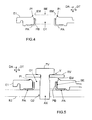
- the ring BE is introduced, for example manually (or by means of of a tool), inside the first orifice 01 of a first element E1, as illustrated on the figures 3 and 4 .
- its two end edges BF are brought together so as to slightly reduce its dimensions, and then it is introduced into the first orifice 01, for example by a rear face of the first element E1.
- the BE ring Once the BE ring is positioned, it releases its two end edges BF so that its wall PB is in contact with the wall of the first element E1 which defines the first orifice 01.
- its wall PB may comprise, as illustrated on the Figures 1 to 5 at least one holding element EM intended to secure it to the first element E1 in a final position in which an end portion of at least one of its two end edges BF protrudes out of the first orifice O1.
- each holding member EM may be formed at a first free end of the wall PB which contains each end edge portion BF which is intended to project out of the first hole 01. But this is not required . It would be possible to define at least one holding element EM in an intermediate zone of the wall PB, for example in the form of an outwardly protruding projection intended to be housed in a recess of homologous shape defined in the wall delimiting the first orifice 01.
- the two holding elements EM are arranged in the form of a flexible tab (or fin) which is intended to rest on a corresponding inclined portion PI which is situated at the periphery of the first orifice 01.
- each inclined portion PI may for example be defined in a notch of the wall which defines the first orifice 01.
- each flexible leg EM may for example be made by cutting (or machining) and then folding the PB wall.
- the flexible tabs EM When the ring BE is introduced into the first orifice 01, the flexible tabs EM are pushed towards the inside of the ring BE and thus separated from their rest position. And, when the first free end of the wall PB reaches the level of the notches where the inclined portions PI are formed, the flexible tabs EM are released from their stress and come to bear on the inclined parts PI, as illustrated on FIG. figure 4 .
- the wall PB of the ring BE may, as illustrated in the figures, comprise a second end, opposite to the first (including the flexible tabs EM), and provided with at least one support lug AP oriented outwards in a substantially radial direction (or transverse direction DT).
- each support leg PA can be supported on the second element E2, thus helping to prevent the first element E1 from creeping at its first orifice O1, as illustrated in FIG. figure 5 .
- the first element E1 (equipped with its ring BE) is placed against the second element E2 so that their first 01 and second 02 orifices are opposite one another.
- the threaded spindle AF is screwed in the second orifice 02 until the TV head of the screwing element V compresses axially (according to DA) the end portion of the end edge BF of the ring BE, which projects out of the first orifice 01.
- the screwing element V may optionally comprise an RV washer traversed by its threaded axis AX and in contact with its TV head, as shown in FIG. figure 5 .
- the TV head compresses the BE ring axially via the RV washer.
- the invention is not limited to embodiments of expandable ring assembly consisting of a first element equipped with an expandable ring, and fixing method described above, only by way of example, but it encompasses all the variants that can be considered by those skilled in the art within the scope of the claims below.
Landscapes
- Engineering & Computer Science (AREA)
- General Engineering & Computer Science (AREA)
- Mechanical Engineering (AREA)
- Connection Of Plates (AREA)
- Dowels (AREA)
Applications Claiming Priority (1)
| Application Number | Priority Date | Filing Date | Title |
|---|---|---|---|
| FR0760281A FR2925628B1 (fr) | 2007-12-21 | 2007-12-21 | Bague expansible pour la fixation d'un element sur un autre element, et procede de fixation correspondant |
Publications (3)
| Publication Number | Publication Date |
|---|---|
| EP2072835A2 true EP2072835A2 (de) | 2009-06-24 |
| EP2072835A3 EP2072835A3 (de) | 2010-06-30 |
| EP2072835B1 EP2072835B1 (de) | 2012-09-26 |
Family
ID=39680892
Family Applications (1)
| Application Number | Title | Priority Date | Filing Date |
|---|---|---|---|
| EP20080169120 Not-in-force EP2072835B1 (de) | 2007-12-21 | 2008-11-14 | Dehnring für die Befestigung eines Elements auf einem anderen und entsprechendes Befestigungsverfahren |
Country Status (3)
| Country | Link |
|---|---|
| EP (1) | EP2072835B1 (de) |
| ES (1) | ES2390623T3 (de) |
| FR (1) | FR2925628B1 (de) |
Family Cites Families (3)
| Publication number | Priority date | Publication date | Assignee | Title |
|---|---|---|---|---|
| DE8625410U1 (de) * | 1986-09-23 | 1986-11-27 | Preh-Werke GmbH & Co. KG, 97616 Bad Neustadt | An einem Träger festgelegtes elektrisches Bauelement |
| FR2800810B1 (fr) * | 1999-11-09 | 2002-01-18 | Gobin Daude | Dispositif de fixation, notamment pour la fixation d'une piece d'habillage, telle qu'une aile en matiere plastique contre un support tel qu'une piece de carrosserie |
| DE10063880B4 (de) * | 2000-12-21 | 2004-12-09 | Dr.Ing.H.C. F. Porsche Ag | Einstellelement zur Befestigung einer Scheinwerferanordnung an einem Fahrzeug |
-
2007
- 2007-12-21 FR FR0760281A patent/FR2925628B1/fr not_active Expired - Fee Related
-
2008
- 2008-11-14 EP EP20080169120 patent/EP2072835B1/de not_active Not-in-force
- 2008-11-14 ES ES08169120T patent/ES2390623T3/es active Active
Also Published As
| Publication number | Publication date |
|---|---|
| FR2925628B1 (fr) | 2012-08-24 |
| ES2390623T3 (es) | 2012-11-14 |
| FR2925628A1 (fr) | 2009-06-26 |
| EP2072835B1 (de) | 2012-09-26 |
| EP2072835A3 (de) | 2010-06-30 |
Similar Documents
| Publication | Publication Date | Title |
|---|---|---|
| FR2552151A1 (fr) | Charniere de porte de vehicule automobile | |
| FR2790046A1 (fr) | Dispositif de fixation de deux panneaux ou analogues forme de deux pieces cooperantes | |
| FR2968366A1 (fr) | Clip de fixation elastique. | |
| FR3099459A1 (fr) | Déflecteur aérodynamique destiné à être fixé contre le soubassement de caisse d’un véhicule | |
| FR3042831A1 (fr) | Rivet auto-perceur a haute resistance mecanique a l'arrachement et au cisaillement | |
| EP2072835B1 (de) | Dehnring für die Befestigung eines Elements auf einem anderen und entsprechendes Befestigungsverfahren | |
| EP3401559B1 (de) | Anti-vibrationsvorrichtung mit vorbefestingungsfunktion, für eine vorrichtung. | |
| EP3394455A1 (de) | Stanzniet mit hoher mechanischer festigkeit | |
| EP4010235B1 (de) | Ablenker mit kupplungszungen für ein fahrzeuguntergestell | |
| EP1651503B1 (de) | Verformbarer längsträger für ein kraftfahrzeug | |
| FR3078759A1 (fr) | Dispositif de poulie pour galet tendeur ou enrouleur | |
| FR3007090A1 (fr) | Dispositif de fixation a deux ecrous et deux pattes de maintien | |
| FR3040649A1 (fr) | Dispositif de pre-maintien d’un element et de ses vis avant vissage sur un equipement | |
| FR2958228A1 (fr) | Dispositif de montage d'un boitier de pedale d'accelerateur sur un support dans un vehicule automobile | |
| FR2939853A1 (fr) | Structure de retenue d'un element d'attache. | |
| EP2332783B1 (de) | Ausrüstungsfixierungvorrichtung, mit Immobilisierungmitteln, die sich in den Öffnungen einer Wand Selbstverschließen. | |
| EP2474750B1 (de) | Einheit, die aus einer Halterung und einem Verbindungseinsatz besteht, und Montageverfahren | |
| WO2008139107A1 (fr) | Biellette avant de berceau pour vehicule automobile | |
| FR3014075A1 (fr) | Piece de pre-maintien d'un pedalier a un amplificateur de frein via un tablier de support d'un vehicule, et procede de solidarisation associe | |
| EP2606219B1 (de) | Haltevorrichtung einer stop-start vorrichtung auf einer fahrzeugkarosserie und zusammenbauverfahren der gleichen. | |
| FR2982575A1 (fr) | Piece de support d'une piece de carrosserie sur un vehicule avec syteme d'indexage a glissiere. | |
| FR2952684A1 (fr) | Dispositif d'immobilisation d'un equipement sur un support, et support d'accessoire(s) associe | |
| FR3083757A1 (fr) | Guide d'air en materiau polymere expanse a zone d'appui sur une traverse extreme avant | |
| EP1141652A1 (de) | Vorrichtung und verfahren zum befestigen von einem zünder auf einer geschosshülle | |
| FR2851801A1 (fr) | Dispositif de montage d'une structure rotative sur un axe |
Legal Events
| Date | Code | Title | Description |
|---|---|---|---|
| PUAI | Public reference made under article 153(3) epc to a published international application that has entered the european phase |
Free format text: ORIGINAL CODE: 0009012 |
|
| AK | Designated contracting states |
Kind code of ref document: A2 Designated state(s): AT BE BG CH CY CZ DE DK EE ES FI FR GB GR HR HU IE IS IT LI LT LU LV MC MT NL NO PL PT RO SE SI SK TR |
|
| AX | Request for extension of the european patent |
Extension state: AL BA MK RS |
|
| PUAL | Search report despatched |
Free format text: ORIGINAL CODE: 0009013 |
|
| AK | Designated contracting states |
Kind code of ref document: A3 Designated state(s): AT BE BG CH CY CZ DE DK EE ES FI FR GB GR HR HU IE IS IT LI LT LU LV MC MT NL NO PL PT RO SE SI SK TR |
|
| AX | Request for extension of the european patent |
Extension state: AL BA MK RS |
|
| 17P | Request for examination filed |
Effective date: 20101124 |
|
| AKX | Designation fees paid |
Designated state(s): AT BE BG CH CY CZ DE DK EE ES FI FR GB GR HR HU IE IS IT LI LT LU LV MC MT NL NO PL PT RO SE SI SK TR |
|
| 17Q | First examination report despatched |
Effective date: 20110502 |
|
| GRAP | Despatch of communication of intention to grant a patent |
Free format text: ORIGINAL CODE: EPIDOSNIGR1 |
|
| GRAS | Grant fee paid |
Free format text: ORIGINAL CODE: EPIDOSNIGR3 |
|
| GRAA | (expected) grant |
Free format text: ORIGINAL CODE: 0009210 |
|
| AK | Designated contracting states |
Kind code of ref document: B1 Designated state(s): AT BE BG CH CY CZ DE DK EE ES FI FR GB GR HR HU IE IS IT LI LT LU LV MC MT NL NO PL PT RO SE SI SK TR |
|
| REG | Reference to a national code |
Ref country code: GB Ref legal event code: FG4D Free format text: NOT ENGLISH |
|
| REG | Reference to a national code |
Ref country code: CH Ref legal event code: EP |
|
| REG | Reference to a national code |
Ref country code: AT Ref legal event code: REF Ref document number: 577195 Country of ref document: AT Kind code of ref document: T Effective date: 20121015 |
|
| REG | Reference to a national code |
Ref country code: IE Ref legal event code: FG4D Free format text: LANGUAGE OF EP DOCUMENT: FRENCH |
|
| REG | Reference to a national code |
Ref country code: ES Ref legal event code: FG2A Ref document number: 2390623 Country of ref document: ES Kind code of ref document: T3 Effective date: 20121114 |
|
| REG | Reference to a national code |
Ref country code: DE Ref legal event code: R096 Ref document number: 602008018960 Country of ref document: DE Effective date: 20121122 |
|
| PG25 | Lapsed in a contracting state [announced via postgrant information from national office to epo] |
Ref country code: HR Free format text: LAPSE BECAUSE OF FAILURE TO SUBMIT A TRANSLATION OF THE DESCRIPTION OR TO PAY THE FEE WITHIN THE PRESCRIBED TIME-LIMIT Effective date: 20120926 Ref country code: FI Free format text: LAPSE BECAUSE OF FAILURE TO SUBMIT A TRANSLATION OF THE DESCRIPTION OR TO PAY THE FEE WITHIN THE PRESCRIBED TIME-LIMIT Effective date: 20120926 Ref country code: LT Free format text: LAPSE BECAUSE OF FAILURE TO SUBMIT A TRANSLATION OF THE DESCRIPTION OR TO PAY THE FEE WITHIN THE PRESCRIBED TIME-LIMIT Effective date: 20120926 Ref country code: NO Free format text: LAPSE BECAUSE OF FAILURE TO SUBMIT A TRANSLATION OF THE DESCRIPTION OR TO PAY THE FEE WITHIN THE PRESCRIBED TIME-LIMIT Effective date: 20121226 |
|
| REG | Reference to a national code |
Ref country code: AT Ref legal event code: MK05 Ref document number: 577195 Country of ref document: AT Kind code of ref document: T Effective date: 20120926 |
|
| REG | Reference to a national code |
Ref country code: LT Ref legal event code: MG4D Effective date: 20120926 Ref country code: ES Ref legal event code: GC2A Effective date: 20130213 |
|
| REG | Reference to a national code |
Ref country code: NL Ref legal event code: VDEP Effective date: 20120926 |
|
| PG25 | Lapsed in a contracting state [announced via postgrant information from national office to epo] |
Ref country code: LV Free format text: LAPSE BECAUSE OF FAILURE TO SUBMIT A TRANSLATION OF THE DESCRIPTION OR TO PAY THE FEE WITHIN THE PRESCRIBED TIME-LIMIT Effective date: 20120926 Ref country code: GR Free format text: LAPSE BECAUSE OF FAILURE TO SUBMIT A TRANSLATION OF THE DESCRIPTION OR TO PAY THE FEE WITHIN THE PRESCRIBED TIME-LIMIT Effective date: 20121227 Ref country code: SI Free format text: LAPSE BECAUSE OF FAILURE TO SUBMIT A TRANSLATION OF THE DESCRIPTION OR TO PAY THE FEE WITHIN THE PRESCRIBED TIME-LIMIT Effective date: 20120926 Ref country code: SE Free format text: LAPSE BECAUSE OF FAILURE TO SUBMIT A TRANSLATION OF THE DESCRIPTION OR TO PAY THE FEE WITHIN THE PRESCRIBED TIME-LIMIT Effective date: 20120926 |
|
| REG | Reference to a national code |
Ref country code: GB Ref legal event code: 746 Effective date: 20130215 |
|
| REG | Reference to a national code |
Ref country code: DE Ref legal event code: R084 Ref document number: 602008018960 Country of ref document: DE Effective date: 20130206 |
|
| PG25 | Lapsed in a contracting state [announced via postgrant information from national office to epo] |
Ref country code: CZ Free format text: LAPSE BECAUSE OF FAILURE TO SUBMIT A TRANSLATION OF THE DESCRIPTION OR TO PAY THE FEE WITHIN THE PRESCRIBED TIME-LIMIT Effective date: 20120926 Ref country code: EE Free format text: LAPSE BECAUSE OF FAILURE TO SUBMIT A TRANSLATION OF THE DESCRIPTION OR TO PAY THE FEE WITHIN THE PRESCRIBED TIME-LIMIT Effective date: 20120926 Ref country code: RO Free format text: LAPSE BECAUSE OF FAILURE TO SUBMIT A TRANSLATION OF THE DESCRIPTION OR TO PAY THE FEE WITHIN THE PRESCRIBED TIME-LIMIT Effective date: 20120926 Ref country code: IS Free format text: LAPSE BECAUSE OF FAILURE TO SUBMIT A TRANSLATION OF THE DESCRIPTION OR TO PAY THE FEE WITHIN THE PRESCRIBED TIME-LIMIT Effective date: 20130126 Ref country code: NL Free format text: LAPSE BECAUSE OF FAILURE TO SUBMIT A TRANSLATION OF THE DESCRIPTION OR TO PAY THE FEE WITHIN THE PRESCRIBED TIME-LIMIT Effective date: 20120926 |
|
| BERE | Be: lapsed |
Owner name: PEUGEOT CITROEN AUTOMOBILES S.A. Effective date: 20121130 |
|
| PG25 | Lapsed in a contracting state [announced via postgrant information from national office to epo] |
Ref country code: PL Free format text: LAPSE BECAUSE OF FAILURE TO SUBMIT A TRANSLATION OF THE DESCRIPTION OR TO PAY THE FEE WITHIN THE PRESCRIBED TIME-LIMIT Effective date: 20120926 Ref country code: CY Free format text: LAPSE BECAUSE OF FAILURE TO SUBMIT A TRANSLATION OF THE DESCRIPTION OR TO PAY THE FEE WITHIN THE PRESCRIBED TIME-LIMIT Effective date: 20120926 Ref country code: PT Free format text: LAPSE BECAUSE OF FAILURE TO SUBMIT A TRANSLATION OF THE DESCRIPTION OR TO PAY THE FEE WITHIN THE PRESCRIBED TIME-LIMIT Effective date: 20130128 Ref country code: SK Free format text: LAPSE BECAUSE OF FAILURE TO SUBMIT A TRANSLATION OF THE DESCRIPTION OR TO PAY THE FEE WITHIN THE PRESCRIBED TIME-LIMIT Effective date: 20120926 |
|
| PG25 | Lapsed in a contracting state [announced via postgrant information from national office to epo] |
Ref country code: AT Free format text: LAPSE BECAUSE OF FAILURE TO SUBMIT A TRANSLATION OF THE DESCRIPTION OR TO PAY THE FEE WITHIN THE PRESCRIBED TIME-LIMIT Effective date: 20120926 |
|
| REG | Reference to a national code |
Ref country code: CH Ref legal event code: PL |
|
| PG25 | Lapsed in a contracting state [announced via postgrant information from national office to epo] |
Ref country code: BG Free format text: LAPSE BECAUSE OF FAILURE TO SUBMIT A TRANSLATION OF THE DESCRIPTION OR TO PAY THE FEE WITHIN THE PRESCRIBED TIME-LIMIT Effective date: 20121226 Ref country code: LI Free format text: LAPSE BECAUSE OF NON-PAYMENT OF DUE FEES Effective date: 20121130 Ref country code: DK Free format text: LAPSE BECAUSE OF FAILURE TO SUBMIT A TRANSLATION OF THE DESCRIPTION OR TO PAY THE FEE WITHIN THE PRESCRIBED TIME-LIMIT Effective date: 20120926 Ref country code: CH Free format text: LAPSE BECAUSE OF NON-PAYMENT OF DUE FEES Effective date: 20121130 |
|
| PLBE | No opposition filed within time limit |
Free format text: ORIGINAL CODE: 0009261 |
|
| STAA | Information on the status of an ep patent application or granted ep patent |
Free format text: STATUS: NO OPPOSITION FILED WITHIN TIME LIMIT |
|
| REG | Reference to a national code |
Ref country code: IE Ref legal event code: MM4A |
|
| PG25 | Lapsed in a contracting state [announced via postgrant information from national office to epo] |
Ref country code: BE Free format text: LAPSE BECAUSE OF NON-PAYMENT OF DUE FEES Effective date: 20121130 |
|
| 26N | No opposition filed |
Effective date: 20130627 |
|
| REG | Reference to a national code |
Ref country code: DE Ref legal event code: R097 Ref document number: 602008018960 Country of ref document: DE Effective date: 20130627 |
|
| PG25 | Lapsed in a contracting state [announced via postgrant information from national office to epo] |
Ref country code: IE Free format text: LAPSE BECAUSE OF NON-PAYMENT OF DUE FEES Effective date: 20121114 |
|
| PG25 | Lapsed in a contracting state [announced via postgrant information from national office to epo] |
Ref country code: MT Free format text: LAPSE BECAUSE OF FAILURE TO SUBMIT A TRANSLATION OF THE DESCRIPTION OR TO PAY THE FEE WITHIN THE PRESCRIBED TIME-LIMIT Effective date: 20120926 |
|
| PG25 | Lapsed in a contracting state [announced via postgrant information from national office to epo] |
Ref country code: TR Free format text: LAPSE BECAUSE OF FAILURE TO SUBMIT A TRANSLATION OF THE DESCRIPTION OR TO PAY THE FEE WITHIN THE PRESCRIBED TIME-LIMIT Effective date: 20120926 Ref country code: MC Free format text: LAPSE BECAUSE OF NON-PAYMENT OF DUE FEES Effective date: 20121130 |
|
| PG25 | Lapsed in a contracting state [announced via postgrant information from national office to epo] |
Ref country code: LU Free format text: LAPSE BECAUSE OF NON-PAYMENT OF DUE FEES Effective date: 20121114 |
|
| PG25 | Lapsed in a contracting state [announced via postgrant information from national office to epo] |
Ref country code: HU Free format text: LAPSE BECAUSE OF FAILURE TO SUBMIT A TRANSLATION OF THE DESCRIPTION OR TO PAY THE FEE WITHIN THE PRESCRIBED TIME-LIMIT Effective date: 20081114 |
|
| REG | Reference to a national code |
Ref country code: FR Ref legal event code: PLFP Year of fee payment: 8 |
|
| REG | Reference to a national code |
Ref country code: FR Ref legal event code: PLFP Year of fee payment: 9 |
|
| PGFP | Annual fee paid to national office [announced via postgrant information from national office to epo] |
Ref country code: DE Payment date: 20161020 Year of fee payment: 9 Ref country code: GB Payment date: 20161027 Year of fee payment: 9 |
|
| PGFP | Annual fee paid to national office [announced via postgrant information from national office to epo] |
Ref country code: IT Payment date: 20161025 Year of fee payment: 9 Ref country code: ES Payment date: 20161024 Year of fee payment: 9 |
|
| REG | Reference to a national code |
Ref country code: FR Ref legal event code: PLFP Year of fee payment: 10 |
|
| PGFP | Annual fee paid to national office [announced via postgrant information from national office to epo] |
Ref country code: FR Payment date: 20171020 Year of fee payment: 10 |
|
| REG | Reference to a national code |
Ref country code: DE Ref legal event code: R119 Ref document number: 602008018960 Country of ref document: DE |
|
| REG | Reference to a national code |
Ref country code: FR Ref legal event code: CA Effective date: 20180312 Ref country code: FR Ref legal event code: CD Owner name: PEUGEOT CITROEN AUTOMOBILES SA, FR Effective date: 20180312 |
|
| GBPC | Gb: european patent ceased through non-payment of renewal fee |
Effective date: 20171114 |
|
| PG25 | Lapsed in a contracting state [announced via postgrant information from national office to epo] |
Ref country code: IT Free format text: LAPSE BECAUSE OF NON-PAYMENT OF DUE FEES Effective date: 20171114 Ref country code: DE Free format text: LAPSE BECAUSE OF NON-PAYMENT OF DUE FEES Effective date: 20180602 |
|
| PG25 | Lapsed in a contracting state [announced via postgrant information from national office to epo] |
Ref country code: GB Free format text: LAPSE BECAUSE OF NON-PAYMENT OF DUE FEES Effective date: 20171114 |
|
| PG25 | Lapsed in a contracting state [announced via postgrant information from national office to epo] |
Ref country code: ES Free format text: LAPSE BECAUSE OF NON-PAYMENT OF DUE FEES Effective date: 20171115 |
|
| PG25 | Lapsed in a contracting state [announced via postgrant information from national office to epo] |
Ref country code: FR Free format text: LAPSE BECAUSE OF NON-PAYMENT OF DUE FEES Effective date: 20181130 |