EP2072818A1 - Metallische Flachdichtung und Ihre Verwendung - Google Patents
Metallische Flachdichtung und Ihre Verwendung Download PDFInfo
- Publication number
- EP2072818A1 EP2072818A1 EP07025025A EP07025025A EP2072818A1 EP 2072818 A1 EP2072818 A1 EP 2072818A1 EP 07025025 A EP07025025 A EP 07025025A EP 07025025 A EP07025025 A EP 07025025A EP 2072818 A1 EP2072818 A1 EP 2072818A1
- Authority
- EP
- European Patent Office
- Prior art keywords
- flat gasket
- metallic flat
- gasket according
- wave
- sealing
- Prior art date
- Legal status (The legal status is an assumption and is not a legal conclusion. Google has not performed a legal analysis and makes no representation as to the accuracy of the status listed.)
- Withdrawn
Links
Images


Classifications
-
- F—MECHANICAL ENGINEERING; LIGHTING; HEATING; WEAPONS; BLASTING
- F16—ENGINEERING ELEMENTS AND UNITS; GENERAL MEASURES FOR PRODUCING AND MAINTAINING EFFECTIVE FUNCTIONING OF MACHINES OR INSTALLATIONS; THERMAL INSULATION IN GENERAL
- F16J—PISTONS; CYLINDERS; SEALINGS
- F16J15/00—Sealings
- F16J15/02—Sealings between relatively-stationary surfaces
- F16J15/06—Sealings between relatively-stationary surfaces with solid packing compressed between sealing surfaces
- F16J15/08—Sealings between relatively-stationary surfaces with solid packing compressed between sealing surfaces with exclusively metal packing
- F16J15/0818—Flat gaskets
-
- F—MECHANICAL ENGINEERING; LIGHTING; HEATING; WEAPONS; BLASTING
- F04—POSITIVE - DISPLACEMENT MACHINES FOR LIQUIDS; PUMPS FOR LIQUIDS OR ELASTIC FLUIDS
- F04B—POSITIVE-DISPLACEMENT MACHINES FOR LIQUIDS; PUMPS
- F04B1/00—Multi-cylinder machines or pumps characterised by number or arrangement of cylinders
- F04B1/04—Multi-cylinder machines or pumps characterised by number or arrangement of cylinders having cylinders in star- or fan-arrangement
- F04B1/0404—Details or component parts
- F04B1/0448—Sealing means, e.g. for shafts or housings
-
- F—MECHANICAL ENGINEERING; LIGHTING; HEATING; WEAPONS; BLASTING
- F04—POSITIVE - DISPLACEMENT MACHINES FOR LIQUIDS; PUMPS FOR LIQUIDS OR ELASTIC FLUIDS
- F04B—POSITIVE-DISPLACEMENT MACHINES FOR LIQUIDS; PUMPS
- F04B53/00—Component parts, details or accessories not provided for in, or of interest apart from, groups F04B1/00 - F04B23/00 or F04B39/00 - F04B47/00
- F04B53/16—Casings; Cylinders; Cylinder liners or heads; Fluid connections
-
- F—MECHANICAL ENGINEERING; LIGHTING; HEATING; WEAPONS; BLASTING
- F16—ENGINEERING ELEMENTS AND UNITS; GENERAL MEASURES FOR PRODUCING AND MAINTAINING EFFECTIVE FUNCTIONING OF MACHINES OR INSTALLATIONS; THERMAL INSULATION IN GENERAL
- F16J—PISTONS; CYLINDERS; SEALINGS
- F16J15/00—Sealings
- F16J15/02—Sealings between relatively-stationary surfaces
- F16J15/06—Sealings between relatively-stationary surfaces with solid packing compressed between sealing surfaces
- F16J15/08—Sealings between relatively-stationary surfaces with solid packing compressed between sealing surfaces with exclusively metal packing
- F16J15/0818—Flat gaskets
- F16J15/0825—Flat gaskets laminated
- F16J15/0831—Flat gaskets laminated with mounting aids
-
- F—MECHANICAL ENGINEERING; LIGHTING; HEATING; WEAPONS; BLASTING
- F16—ENGINEERING ELEMENTS AND UNITS; GENERAL MEASURES FOR PRODUCING AND MAINTAINING EFFECTIVE FUNCTIONING OF MACHINES OR INSTALLATIONS; THERMAL INSULATION IN GENERAL
- F16J—PISTONS; CYLINDERS; SEALINGS
- F16J15/00—Sealings
- F16J15/02—Sealings between relatively-stationary surfaces
- F16J15/06—Sealings between relatively-stationary surfaces with solid packing compressed between sealing surfaces
- F16J15/08—Sealings between relatively-stationary surfaces with solid packing compressed between sealing surfaces with exclusively metal packing
- F16J15/0818—Flat gaskets
- F16J2015/0856—Flat gaskets with a non-metallic coating or strip
Definitions
- the invention relates to a metallic flat gasket, with which at least three recesses, of which at least one encloses a high-pressure region and the other two respectively lower pressure regions, are sealed so that at least the high-pressure and low-pressure regions are independent of one another on the basis of different embossed sealing elements be sealed. Furthermore, the invention relates to the use of this metallic flat gasket for sealing a pump against a cylinder head, a suction line and a high pressure line. On the cylinder head, a bushing is usually attached, which protrudes in the direction of the pump or in this.
- the invention preferably relates to the use of a metallic flat gasket for sealing a high-pressure fuel pump, in particular for a common high-pressure accumulator, the so-called common rail.
- the high-pressure region has pressures of more than 130 MPa, preferably of more than 160 MPa, while the low-pressure region has pressures of less than 1.5 MPa, preferably less than 1 MPa.
- the outer edges of the through-openings of the high-pressure region and of the cylinder head bushing, that is to say of the low-pressure region are usually less than 15 mm apart.
- a sealing device for a transition region on high-pressure components is known.
- the sealing device consists of two separate components, namely a sealing ring for the high pressure area and an additional flat gasket for the low pressure area.
- the assembly of several components is always associated with additional effort.
- it requires the sealing construction of DE 100 42 305 A1 in that a groove for receiving the sealing ring is formed in one of the two components to be sealed against each other. Again, this is associated with considerable effort.
- this Sealing system only one single sealing line.
- plastic, in particular elastomer, or rubber and on the other hand metal is proposed.
- Vehicles must be used in a wide ambient temperature range. Vehicle manufacturers therefore demand from their suppliers the functionality of vehicle parts in a temperature range of -40 ° to + 140 °. Plastics and rubbers become brittle at minus temperatures and can reach temperatures below -25 ° C DE 100 42 305 A1 no longer fulfill the required sealing effect. Furthermore, it allows the sealing device according to the DE 100 42 305 A1 not to bias the components against each other.
- Another sealing device for such a transition to high-pressure components is known from DE 103 10 124 A1 known. This has around the high pressure area as well as around the intake area sealing beads, these sealing beads are surrounded as well as the opening for the cylinder head or attached to the cylinder head socket of another circumferential sealing bead.
- the sealing beads around the high-pressure region as well as around the suction region are preferably profiled coaxially. In this solution, a relatively large amount of bolt force is required for the long circumferential sealing bead. Likewise, the profiled design of the sealing bead at the intake area requires a lot of bolt force.
- the flat gasket should have a seal for the high-pressure region, which is formed independently of the sealing of the low-pressure region (cylinder head or bushing and intake region) and thereby enables separate leakage control.
- the seal should be designed so that the highest possible proportion of the screw forces on the high pressure area acts.
- the seal should be constructed so that it causes a bias of the components to be sealed.
- the invention thus relates to a metallic flat gasket for sealing a first recess for a socket attached to a cylinder head, a second recess for a suction channel and at least one third recess for a high-pressure channel, which also contains openings for fastening means.
- a system of high-pressure pump and this sealing against other components metallic flat gasket and from yet another point of view, a system of high-pressure pump, metallic seal, the common rail conductive high pressure area, intake and cylinder head, the latter usually still has a facing in the direction of the high-pressure pump jack.
- the flat gasket has a wave-shaped profiling which surrounds the at least one third recess, that is to say the high-pressure region.
- Both the first recess, ie the recess for the bush attached to the cylinder head, and the second recess, ie the recess for the intake channel are sealed by a sealing bead that either surrounds both recesses together or both separately.
- the sealing beads are guided so that they do not enclose fastener openings.
- the wave-shaped profiling and the at least one sealing bead are formed independently of one another, so the areas sealed by them do not overlap. As a result, it can be independently controlled for each sealing area immediately after assembly, whether it is sealed.
- the metallic flat gasket according to the invention can consist of a plurality of metal layers connected to one another, for example by means of riveting, clinching or welding, but it is preferably made of them a single metal layer.
- the metal layer is preferably formed from a spring-hard material, wherein the adjustment of this property can also be done by temperature treatment during the manufacturing process. For reasons of corrosion protection, stainless steel grades, in particular stainless steel or galvanized steel, are preferred. Galvanization is not considered a coating in the context of the present invention.
- the thickness of the metal layer is in the range of 150 to 300 .mu.m, preferably 200 to 250 .mu.m thick metal sheets are used.
- the metallic flat gasket may be partially coated on one or both surfaces, in multilayer embodiments also on internal surfaces.
- the coating is preferably applied in the region of the sealing beads and on the areas adjacent thereto.
- the sealing beads provide for the macro-seal, the coating for the micro-seal. Therefore, relatively small coating thicknesses are sufficient.
- the thickness of the coating is typically 10 to 30 ⁇ m, preferably 12 to 18 ⁇ m.
- a coating of the wave-shaped profiling is not preferred since there is the risk that the coating material will detach and be passed on with the medium, ie in the case of a high-pressure fuel pump, the injection nozzles of the combustion chambers will become clogged.
- the crests or ridges of the wave-shaped profiling must therefore, since they are exposed to strong frictional movements in operation, be absolutely free of any coating. It is conceivable that a very well-adhering filling is introduced into the recesses of the wave-shaped profiling in order to regulate the rigidity of the profiling. However, this is not necessary in most cases.
- the coating material used is FPM (vinylidene fluoride-hexafluoropropylene copolymer), silicone rubber, NBR rubber (acrylic butadiene rubber), PUR (polyurethane), NR (natural rubber), FFKM (perfluororubber), SBR (styrene-butadiene rubber), BR ( Butyl rubber), FVSQ (fluorosilicone), CSM (chlorosulfonated polyethylene) and silicone or epoxy resins in question.
- FPM vinylene fluoride-hexafluoropropylene copolymer
- silicone rubber NBR rubber (acrylic butadiene rubber), PUR (polyurethane), NR (natural rubber), FFKM (perfluororubber), SBR (styrene-butadiene rubber), BR ( Butyl rubber), FVSQ (fluorosilicone), CSM (chlorosulfonated polyethylene) and silicone or epoxy resins in question.
- the cross sections of the wave-shaped profiling may be formed substantially sinusoidal or be formed of trapezoidal elevations and depressions. Also transitional forms between these two forms are possible. It is crucial that a flank area is formed between elevations and depressions by reducing the material thickness in relation to the elevations and depressions. By pressing this flank area, it comes to a concentration of material and thus to a stiffening.
- the maximum material thickness in the region of the elevations and depressions is at least 10%, preferably at least 13% and particularly preferably at least 15% greater than the minimum material thickness in the flank region, in each case measured perpendicular to the material profile.
- the micro-seal to compensate for the roughness of the components to be sealed is achieved in that the combs on their support surfaces in these components cause plastic deformation.
- the depth of the deformations is in the range of half to double the surface roughness of the components, that is about 2 to 20 microns.
- the depth of the deformations also depends on the material of the component to be sealed, but also on the radius of the ridges of the elevations of the profiling, this is usually in the range of 100 to 250 .mu.m, preferably between 120 and 200 microns.
- the wave-shaped profiling is formed substantially concentrically around the high-pressure opening. It is fundamentally possible for the wavy profiling to meander around the recess, that is, to run in serpentine lines. In this embodiment, it is sufficient if the profiling forms a survey that protrudes on one side of the plane of the gasket layer and forms a recess on the other side.
- this embodiment has the disadvantage that, despite a relatively large space requirement, it forms only a self-contained sealing line. Multiple sealing lines with the same or smaller footprint result from a wave-shaped profiling, wherein the elevations and depressions are formed concentrically around the recess around.
- the profiling is usually designed so that it has 2 to 5 periods of a wave.
- the high-pressure region may have different geometries.
- the recess may be substantially circular, but may also have oval or ellipsoidal shapes.
- the high pressure area consists of several openings, which are then preferably each sealed individually by a wave-shaped profiling.
- a part of the elevations and depressions in the area between the openings expires or united with the elevations or depressions of the other profiling.
- a common seal by means of a single wave-shaped profiling, which rotates around all high-pressure openings together, is also conceivable.
- the wave-shaped profiling When installing the seal and tightening the fasteners, the wave-shaped profiling with its limited elasticity ensures that in the region of the profiling the adjoining components undergo a bias. This has the consequence that in operation, when the seal is exposed to constantly changing pressure conditions, the distance between the seal and adjacent component barely changed despite the pressure changes and the seal itself has to make only small spring travel. As a result, the durability is significantly improved.
- the corrugated profiling is perfectly adequate for the sealing of the high pressure area, a combination with an e.g. Concentric surrounding bead is therefore neither necessary nor useful.
- the wave-shaped profiling is uniform in both its radial and its longitudinal course (i.e., along its circumference), i. with constant heights of elevations and depressions, constant distances and widths of elevations and depressions and constant radii. At most, the width of elevations and depressions topographical adjustments can be made.
- the at least one sealing bead can be formed as a full bead, but for reasons of space, the half-bead shape is preferred.
- the sealing bead has a greater elasticity than the wave-shaped profiling, which is why the bead is formed higher than the wave-shaped profiling.
- the height of the sealing bead is 105 to 350%, preferably 110 to 200% and particularly preferably 115 to 150% of the height of the wave-shaped profiling.
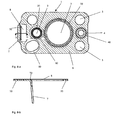
- FIG. 1 A first exemplary embodiment of a metallic flat gasket 1 according to the invention is shown in FIG FIG. 1 shown.
- the recess 2 for the high-pressure region through which fuel is transported to the common rail of the injection system is surrounded by a wave-shaped profiling 20.
- another recess 3 which is intended to seal between the cylinder head and the pump or around a bush attached to the adjacent cylinder head around.
- the recess 4 connects, which serves to seal the suction line.
- the recesses 3 and 4 each surround only areas exposed to low pressure and are sealed with beads 30 and 40, which are formed independently of each other. On the beads and in these adjoining areas, the sealing surface is provided with a coating 6.
- the coating extends directly to the edge of the openings 3 and 4 zoom. In the region between the recesses 2 and 3, the coating 6 was applied so that they everywhere a minimum distance, for example at least 300 microns, preferably at least 500 microns and more preferably at least 800 microns, complies with the wave-shaped profiling 20.
- the three fluid ports 2, 3 and 4 are surrounded by four fastener openings 5.
- Possible embodiments for the wave-shaped profiling 20 are in the sections of the Figures 1-a to 1-c shown.
- the only gasket layer of the gasket 1 is shown in FIG Figure 1-a on the top two elevations 21 and three wells 22, so about 2.5 wave periods.
- a flank region 23 is formed in each case, in which the material thickness 230 is less than the material thickness 221 in the region of the elevations 21 and the recesses 22.
- the ridges of the elevations 22 appear relatively flat, on However, real part they have a radius r, which must be small so that the wave-shaped profiling 6 in the adjacent component surfaces can cause plastic deformation.
- FIG. 1 While the embodiment of the Figure 1-a is free from any coating, that of the Figure 1-b a chamber 24 chambered in the depressions 22, the height of which here corresponds to approximately half the height between elevations 21 and depressions 22.
- the embodiment of Figure 1-c is different from those of Figures 1-a and 1-b on the one hand by the increased wave period number (3,5).
- the shape of the projections 21 and recesses 22 is more similar to a trapezoidal shape compared to the other embodiments.
- the embodiment according to FIG. 2 is different from the after FIG. 1 in that no coating is present on the upwardly facing surface. Details on the sequence of the sealing elements 20, 30 and 40 and the recesses 2, 3 and 4 are in the sectional views in FIGS. 3 and 4 illustrated.
- the wave-shaped profiling 20 is made slightly wider than the inclined portion of the beads 30 and 40.
- the two sealing beads 30 and 40 are each designed as half beads and have similar heights and widths.
- FIGS. 5 and 6 represent embodiments of the metallic flat gasket according to the invention, which are different from those of FIG. 2 differ only by the configuration of the recesses 2 for the high pressure area.
- the embodiment of the FIG. 5 equal to two immediately adjacent recesses 2 and 2 ', which are each individually sealed by wave-shaped profilings 20 and 20'.
- the oval high-pressure opening 2 "in FIG. 6 is surrounded by a likewise oval profile 20 "with a wave-shaped cross-section which can be used to simultaneously seal several high-pressure lines passing through the oval recess 2" or, although this will rarely be the case, seal a line with an oval cross-section.
- FIG. 7 demonstrates that the openings 3 and 4 of the low-pressure region can also be sealed by means of a common bead 34.
- the detailed sections A and B show that the wave-shaped profiling 6 on the one hand from a larger number of elevations and depressions, which may be substantially concentric to be sealed opening 2, as shown by the three approximately parallel elevations 21, 21 'and 21 "in Section B.
- the profiling 6 also consist of only a single survey 21 ''', but then meandering along the edge of the sealed opening 2 and their stability and compared to a bead reduced elasticity by their meandering course, in particular the regular expansion in the radial direction to the opening 2 receives.
- Figure 8-a further shows that it is in principle possible to surround also fastener openings 5 of bead-like circumferential cranks. It also becomes clear that the outer contour the metallic flat gasket does not necessarily have to correspond to a rectangle with rounded corners, as was the case in the other embodiments. Rear and projections of the outer contour usually result from the outer shape of the components to be sealed.
- FIG. 9 is the Verpressungs- and springback behavior of the two embossed sealing elements of high pressure area on the one hand and low pressure area on the other hand, so wave-shaped profiling and sealing bead shown.
- a wave-shaped profiling with several elevations and depressions arranged concentrically with respect to the opening was compared with a half bead provided with a coating on both sides. The measurements always take place under preload.
- the dashed line DS represents the spring travel of the sealing bead. It runs relatively flat, while the solid line wP of the wavy profiling runs much steeper. This shows that the sealing bead is much more elastic than the wavy profiling.
- the spring travel of the sealing bead is much larger than the wave-like profiling with the same force, it is always a multiple of the spring travel of the wave-shaped profiling, sometimes more than 10 times.
- the various design options for the sealing bead and the wave-shaped profiling can therefore be assumed that even with a combination of a very stiff sealing bead with a very elastic wave-shaped profiling of the travel of the sealing bead at least 3.5 times, preferably at least 5 times the spring travel is the wave-shaped profiling, wherein the heights of sealing bead and undulating profiling are designed so that their ratio is in the range specified in section [0019].
- FIG. 9 shows that the sealing bead, with its descending branches pointing far in the direction of higher thicknesses, undergoes only negligibly small plastic deformations and the plastic deformation of the undulating profiling is indeed higher than that of the sealing bead, but overall is also very limited.
- FIG. 9 in that the sealing bead has a significantly lower sealing force than the wave-shaped profiling.
Landscapes
- Engineering & Computer Science (AREA)
- General Engineering & Computer Science (AREA)
- Mechanical Engineering (AREA)
- Gasket Seals (AREA)
Priority Applications (1)
| Application Number | Priority Date | Filing Date | Title |
|---|---|---|---|
| EP07025025A EP2072818A1 (de) | 2007-12-21 | 2007-12-21 | Metallische Flachdichtung und Ihre Verwendung |
Applications Claiming Priority (1)
| Application Number | Priority Date | Filing Date | Title |
|---|---|---|---|
| EP07025025A EP2072818A1 (de) | 2007-12-21 | 2007-12-21 | Metallische Flachdichtung und Ihre Verwendung |
Publications (1)
| Publication Number | Publication Date |
|---|---|
| EP2072818A1 true EP2072818A1 (de) | 2009-06-24 |
Family
ID=39308765
Family Applications (1)
| Application Number | Title | Priority Date | Filing Date |
|---|---|---|---|
| EP07025025A Withdrawn EP2072818A1 (de) | 2007-12-21 | 2007-12-21 | Metallische Flachdichtung und Ihre Verwendung |
Country Status (1)
| Country | Link |
|---|---|
| EP (1) | EP2072818A1 (sv) |
Cited By (7)
| Publication number | Priority date | Publication date | Assignee | Title |
|---|---|---|---|---|
| DE102010049958A1 (de) * | 2010-10-28 | 2012-05-03 | Reinz-Dichtungs-Gmbh | Mehrlagige Dichtung und deren Verwendung |
| WO2014206714A1 (de) * | 2013-06-25 | 2014-12-31 | Robert Bosch Gmbh | Dichtung für axialkolbenmaschine mit vibrationsdämpfung |
| WO2015043955A1 (de) * | 2013-09-25 | 2015-04-02 | Elringklinger Ag | Zwischenplatte |
| EP2902614A1 (de) * | 2014-02-03 | 2015-08-05 | Robert Bosch Gmbh | Dichtscheibe für einen kraftstoffinjektor, sowie kraftstoffinjektor mit einer derartigen dichtscheibe |
| WO2017220696A1 (en) * | 2016-06-23 | 2017-12-28 | Delphi International Operations Luxembourg S.À R.L. | Gasket of a front plate of a high pressure pump |
| US10619725B2 (en) | 2013-09-25 | 2020-04-14 | Elringklinger Ag | Intermediate plate and control unit |
| WO2024068794A1 (de) * | 2022-09-27 | 2024-04-04 | Ejot Se & Co. Kg | Ringförmige dichtscheibe |
Citations (10)
| Publication number | Priority date | Publication date | Assignee | Title |
|---|---|---|---|---|
| EP0592140A1 (en) * | 1992-10-01 | 1994-04-13 | Ishikawa Gasket Co. Ltd. | Metal gasket with edge support beads |
| US6036195A (en) * | 1998-03-09 | 2000-03-14 | Ishikawa Gasket Co., Ltd. | Metal gasket with double beads |
| DE10042305A1 (de) | 2000-08-29 | 2002-03-21 | Siemens Ag | Abdichtungsvorrichtung für einen Übergangsbereich an Hochdruckbauteilen |
| EP1306588A2 (en) * | 2001-10-23 | 2003-05-02 | Ishikawa Gasket Co. Ltd. | Metal gasket with partial coating |
| WO2004046547A1 (de) * | 2002-11-15 | 2004-06-03 | Robert Bosch Gmbh | Radialkolbenpumpe mit flächiger dichtung zwischen flansch und gehäuse |
| EP1443251A2 (de) * | 2003-02-03 | 2004-08-04 | Siemens Aktiengesellschaft | Flanscheinheit |
| DE10310124A1 (de) | 2003-03-07 | 2004-09-16 | Siemens Ag | Flachdichtung |
| DE102004034824A1 (de) | 2004-07-19 | 2006-02-16 | Reinz-Dichtungs-Gmbh | Metallische Flachdichtung |
| EP1679457A1 (de) * | 2000-06-15 | 2006-07-12 | Reinz-Dichtungs-Gmbh | Flachdichtung und Verfahren zu ihrer Herstellung |
| DE60125749T2 (de) * | 2000-04-18 | 2007-11-08 | Denso Corp., Kariya | Hochdruckpumpe und zugehörige montagevorrichtung |
-
2007
- 2007-12-21 EP EP07025025A patent/EP2072818A1/de not_active Withdrawn
Patent Citations (10)
| Publication number | Priority date | Publication date | Assignee | Title |
|---|---|---|---|---|
| EP0592140A1 (en) * | 1992-10-01 | 1994-04-13 | Ishikawa Gasket Co. Ltd. | Metal gasket with edge support beads |
| US6036195A (en) * | 1998-03-09 | 2000-03-14 | Ishikawa Gasket Co., Ltd. | Metal gasket with double beads |
| DE60125749T2 (de) * | 2000-04-18 | 2007-11-08 | Denso Corp., Kariya | Hochdruckpumpe und zugehörige montagevorrichtung |
| EP1679457A1 (de) * | 2000-06-15 | 2006-07-12 | Reinz-Dichtungs-Gmbh | Flachdichtung und Verfahren zu ihrer Herstellung |
| DE10042305A1 (de) | 2000-08-29 | 2002-03-21 | Siemens Ag | Abdichtungsvorrichtung für einen Übergangsbereich an Hochdruckbauteilen |
| EP1306588A2 (en) * | 2001-10-23 | 2003-05-02 | Ishikawa Gasket Co. Ltd. | Metal gasket with partial coating |
| WO2004046547A1 (de) * | 2002-11-15 | 2004-06-03 | Robert Bosch Gmbh | Radialkolbenpumpe mit flächiger dichtung zwischen flansch und gehäuse |
| EP1443251A2 (de) * | 2003-02-03 | 2004-08-04 | Siemens Aktiengesellschaft | Flanscheinheit |
| DE10310124A1 (de) | 2003-03-07 | 2004-09-16 | Siemens Ag | Flachdichtung |
| DE102004034824A1 (de) | 2004-07-19 | 2006-02-16 | Reinz-Dichtungs-Gmbh | Metallische Flachdichtung |
Cited By (10)
| Publication number | Priority date | Publication date | Assignee | Title |
|---|---|---|---|---|
| DE102010049958A1 (de) * | 2010-10-28 | 2012-05-03 | Reinz-Dichtungs-Gmbh | Mehrlagige Dichtung und deren Verwendung |
| DE102010049958B4 (de) * | 2010-10-28 | 2012-07-12 | Reinz-Dichtungs-Gmbh | Mehrlagige Dichtung und deren Verwendung |
| WO2014206714A1 (de) * | 2013-06-25 | 2014-12-31 | Robert Bosch Gmbh | Dichtung für axialkolbenmaschine mit vibrationsdämpfung |
| WO2015043955A1 (de) * | 2013-09-25 | 2015-04-02 | Elringklinger Ag | Zwischenplatte |
| CN105593582A (zh) * | 2013-09-25 | 2016-05-18 | 爱尔铃克铃尔股份公司 | 中间板 |
| US10480655B2 (en) | 2013-09-25 | 2019-11-19 | Elringklinger Ag | Intermediate plate |
| US10619725B2 (en) | 2013-09-25 | 2020-04-14 | Elringklinger Ag | Intermediate plate and control unit |
| EP2902614A1 (de) * | 2014-02-03 | 2015-08-05 | Robert Bosch Gmbh | Dichtscheibe für einen kraftstoffinjektor, sowie kraftstoffinjektor mit einer derartigen dichtscheibe |
| WO2017220696A1 (en) * | 2016-06-23 | 2017-12-28 | Delphi International Operations Luxembourg S.À R.L. | Gasket of a front plate of a high pressure pump |
| WO2024068794A1 (de) * | 2022-09-27 | 2024-04-04 | Ejot Se & Co. Kg | Ringförmige dichtscheibe |
Similar Documents
| Publication | Publication Date | Title |
|---|---|---|
| DE102005003017B4 (de) | Metalldichtung | |
| EP1577589B1 (de) | Zylinderkopfdichtung | |
| DE102008062829B4 (de) | Hydrauliksystemsteuerplatte | |
| EP2734754B2 (de) | Flachdichtung | |
| EP1985897A1 (de) | Metallische Flachdichtung | |
| EP2072818A1 (de) | Metallische Flachdichtung und Ihre Verwendung | |
| DE10310014B4 (de) | Zylinderkopf-Flachdichtung | |
| EP2809973B1 (de) | Metallische flachdichtung | |
| WO2006005488A1 (de) | Zylinderkopfdichtung | |
| EP1482218B1 (de) | Zylinderkopfdichtung | |
| DE10117178A1 (de) | Zylinderkopfdichtung | |
| EP1601873B1 (de) | Kombination einer Flachdichtung mit einer Kraftstoffhochdruckpumpe. | |
| EP1875110B1 (de) | Flachdichtung, insbesondere zylinderkopfdichtung | |
| EP3049695B1 (de) | Zwischenplatte und steuereinheit | |
| DE102018203450B4 (de) | Dichtungsanordnung, Fluidregelventil mit einer solchen Dichtungsanordnung und Verwendung eines solchen Fluidregelventils | |
| DE202017107285U1 (de) | Flachdichtung | |
| DE102010013545A1 (de) | Abgasstrang-Flachdichtung | |
| DE102016002582A1 (de) | Flachdichtung, insbesondere Zylinderkopfdichtung | |
| EP3099962B1 (de) | Zylinderkopfdichtung sowie ein eine solche umfassendes abdichtsystem | |
| EP1998086B1 (de) | Metallische Flachdichtung | |
| WO2019038319A1 (de) | Zylinderkopfdichtung | |
| DE102006037180B3 (de) | Platten- oder schalenartiges Bauteil mit einer Dichtfläche | |
| DE102006007270B4 (de) | Flachdichtung | |
| EP3169916B1 (de) | Steuereinheit für fluidbetriebene verbraucher | |
| DE60315320T2 (de) | Zylinderkopfdichtung |
Legal Events
| Date | Code | Title | Description |
|---|---|---|---|
| PUAI | Public reference made under article 153(3) epc to a published international application that has entered the european phase |
Free format text: ORIGINAL CODE: 0009012 |
|
| AK | Designated contracting states |
Kind code of ref document: A1 Designated state(s): AT BE BG CH CY CZ DE DK EE ES FI FR GB GR HU IE IS IT LI LT LU LV MC MT NL PL PT RO SE SI SK TR |
|
| AX | Request for extension of the european patent |
Extension state: AL BA HR MK RS |
|
| AKX | Designation fees paid | ||
| STAA | Information on the status of an ep patent application or granted ep patent |
Free format text: STATUS: THE APPLICATION IS DEEMED TO BE WITHDRAWN |
|
| 18D | Application deemed to be withdrawn |
Effective date: 20091229 |
|
| REG | Reference to a national code |
Ref country code: DE Ref legal event code: 8566 |