EP2072440A2 - Unwinding assisting device and automatic winder comprising the same - Google Patents
Unwinding assisting device and automatic winder comprising the same Download PDFInfo
- Publication number
- EP2072440A2 EP2072440A2 EP08020035A EP08020035A EP2072440A2 EP 2072440 A2 EP2072440 A2 EP 2072440A2 EP 08020035 A EP08020035 A EP 08020035A EP 08020035 A EP08020035 A EP 08020035A EP 2072440 A2 EP2072440 A2 EP 2072440A2
- Authority
- EP
- European Patent Office
- Prior art keywords
- yarn
- regulating member
- stepping motor
- elevating
- lowering
- Prior art date
- Legal status (The legal status is an assumption and is not a legal conclusion. Google has not performed a legal analysis and makes no representation as to the accuracy of the status listed.)
- Granted
Links
- 230000001105 regulatory effect Effects 0.000 claims abstract description 105
- 230000003028 elevating effect Effects 0.000 claims abstract description 42
- 238000004804 winding Methods 0.000 description 25
- 238000005520 cutting process Methods 0.000 description 14
- 230000007246 mechanism Effects 0.000 description 10
- 238000000034 method Methods 0.000 description 9
- 230000008569 process Effects 0.000 description 9
- 230000009467 reduction Effects 0.000 description 7
- 230000007547 defect Effects 0.000 description 6
- 239000000428 dust Substances 0.000 description 4
- 239000000835 fiber Substances 0.000 description 4
- 230000001133 acceleration Effects 0.000 description 2
- 230000008859 change Effects 0.000 description 2
- 238000012423 maintenance Methods 0.000 description 2
- 230000002093 peripheral effect Effects 0.000 description 2
- 238000012545 processing Methods 0.000 description 2
- 238000009825 accumulation Methods 0.000 description 1
- 238000013459 approach Methods 0.000 description 1
- 230000015572 biosynthetic process Effects 0.000 description 1
- 230000000694 effects Effects 0.000 description 1
- 239000012530 fluid Substances 0.000 description 1
- 230000006872 improvement Effects 0.000 description 1
- 238000009434 installation Methods 0.000 description 1
- 239000010687 lubricating oil Substances 0.000 description 1
- 238000005461 lubrication Methods 0.000 description 1
- 239000002184 metal Substances 0.000 description 1
- 238000012986 modification Methods 0.000 description 1
- 230000004048 modification Effects 0.000 description 1
- 238000012544 monitoring process Methods 0.000 description 1
- 230000002265 prevention Effects 0.000 description 1
- 238000005549 size reduction Methods 0.000 description 1
- 238000003860 storage Methods 0.000 description 1
Images


Classifications
-
- B—PERFORMING OPERATIONS; TRANSPORTING
- B65—CONVEYING; PACKING; STORING; HANDLING THIN OR FILAMENTARY MATERIAL
- B65H—HANDLING THIN OR FILAMENTARY MATERIAL, e.g. SHEETS, WEBS, CABLES
- B65H57/00—Guides for filamentary materials; Supports therefor
- B65H57/12—Tubes
-
- B—PERFORMING OPERATIONS; TRANSPORTING
- B65—CONVEYING; PACKING; STORING; HANDLING THIN OR FILAMENTARY MATERIAL
- B65H—HANDLING THIN OR FILAMENTARY MATERIAL, e.g. SHEETS, WEBS, CABLES
- B65H57/00—Guides for filamentary materials; Supports therefor
- B65H57/22—Guides for filamentary materials; Supports therefor adapted to prevent excessive ballooning of material
-
- B—PERFORMING OPERATIONS; TRANSPORTING
- B65—CONVEYING; PACKING; STORING; HANDLING THIN OR FILAMENTARY MATERIAL
- B65H—HANDLING THIN OR FILAMENTARY MATERIAL, e.g. SHEETS, WEBS, CABLES
- B65H57/00—Guides for filamentary materials; Supports therefor
- B65H57/26—Supports for guides
-
- B—PERFORMING OPERATIONS; TRANSPORTING
- B65—CONVEYING; PACKING; STORING; HANDLING THIN OR FILAMENTARY MATERIAL
- B65H—HANDLING THIN OR FILAMENTARY MATERIAL, e.g. SHEETS, WEBS, CABLES
- B65H2701/00—Handled material; Storage means
- B65H2701/30—Handled filamentary material
- B65H2701/31—Textiles threads or artificial strands of filaments
Definitions
- the present invention relates to an automatic winder, and specifically, to an unwinding assisting device that regulates a balloon generated when a yarn is unwound from a yarn supplying bobbin.
- An automatic winder is conventionally known which is configured to regulate a balloon generated when a yarn is unwound from a yarn supplying bobbin.
- the unwinding assisting device lowers a regulating member as an unwinding point of the yarn from the yarn supplying bobbin lowers.
- the unwinding assisting device thus maintains the distance from the unwinding point constant to control formation of the balloon.
- An unwinding assisting device of this kind often comprises a sensor that senses the position of an upper end of the yarn to be unwound, and an elevating and lowering means for elevating and lowering the regulating means.
- the unwinding assisting device is further configured to control the elevating and lowering means such as an air cylinder or a stepping motor as the upper end position of the yarn lowers to lower the regulating member in conjunction with the lowering of the upper end position.
- the Unexamined Japanese Patent Application Publication ( Tokkai-Hei) No. 8-198520 discloses an unwinding assisting device configured to use a stepping motor as the elevating and lowering means.
- An unwinding assisting device in the automatic winder in the Unexamined Japanese Patent Application Publication ( Tokkai-Hei) No. 8-198520 is composed of an elevating and lowering guide for the unwinding assisting device which controls ballooning when the yarn is unwound from the yarn supplying bobbin, a driving device provided within the range of the length of the elevating and lowering guide, and a converting mechanism that converts motion in a direction different from that of elevating and lowering motion of the driving device into elevating and lowering motion.
- the Unexamined Japanese Patent Application Publication ( Tokkai-Hei) No. 8-198520 also discloses that the driving device can be composed of a rack pinion mechanism and a stepping motor operating integrally with the unwinding assisting device.
- the regulating member is desirably returned quickly to the original position to allow a winding operation to be resumed.
- the air cylinder is configured to drive forward and backward a cylinder rod or the like, which is relatively heavy.
- a strong inertia force is generated to impact related components of the device. This may cause a failure or the like.
- an installation space for the air cylinder requires a length almost double the moving distance of the regulating member. Consequently, reducing the size of the device is difficult.
- the Unexamined Japanese Patent Application Publication ( Tokkai-Hei) No. 8-198520 is configured such that the stepping motor itself elevates and lowers together with the elevating and lowering guide (regulating member).
- a holding member supporting the stepping motor also needs to have a certain level of strength and is configured to allow heavy objects to be elevated and lowered.
- the Unexamined Japanese Patent Application Publication ( Tokkai-Hei) No. 8-198520 still has room for improvement in terms of smooth elevating and lowering control, energy saving, impact prevention, and the like.
- electric wiring for the stepping motor needs to be laid out in a complicated form.
- An object of the present invention is to provide an unwinding assisting device for an automatic winder which enables fine-tuning of elevating and lowering of the regulating member and which can prevent a possible impact during elevating or lowering.
- a first aspect of the present invention provides an unwinding assisting device for an automatic winder configured as described below. That is, the unwinding assisting device comprises a regulating member that regulates a balloon generated when a yarn is unwound from a yarn supplying bobbin and an elevating and lowering means for elevating and lowering the regulating means.
- the elevating and lowering means comprises a stepping motor and a belt member that transmits driving of the stepping motor.
- the position of the regulating member can be precisely controlled in very small incremental steps in pulse unit (in an almost nonstep manner) by performing pulse control on the stepping motor.
- the configuration is such that the driving force of the stepping motor is transmitted to the regulating member by a relatively light belt member. This enables a reduction in a possible inertia force during elevating or lowering of the regulating member. Acceleration and deceleration performance is thus improved. Therefore, very precise balloon control can be performed, and a possible excessive impact can be prevented where the regulating member is elevated and lowered at a high speed. Moreover, where a certain impact occurs on the regulating member, the impact is absorbed by the belt member.
- the elevating and lowering means is composed of the stepping motor and the belt member, and thus has a simple configuration. This enables a reduction in the size of the device and in costs. Additionally, where the elevating and lowering stroke of the regulating member is to be changed, the changing operation can be easily performed by making a minor change to the configuration.
- the belt member is preferably a toothed belt.
- the toothed belt can transmit the driving force of the stepping motor without slippage.
- required energy can be appropriately saved, and the elevating and lowering of the regulating member can be further precisely and smoothly controlled.
- a second aspect of the present invention provides an automatic winder configured as follows. That is, the automatic winder comprises the above-described unwinding assisting device, a yarn splicing device that performs a yarn splicing operation, a count means for counting number of pulses transmitted to the stepping motor, and a control section.
- the control section controls the regulating means so that when a yarn unwound from a yarn supplying bobbin is broken or cut, the regulating member is retracted. Furthermore, the control section controls the regulating member so that when the yarn splicing operation by the yarn splicing device is completed, the regulating member is returned to an original position on the basis of a count result from the count means.
- the regulating member can be quickly and accurately moved to the position where the yarn breakage or cutting has occurred, on the basis of a stored count value for the pulse number. This allows the yarn winding operation to be quickly resumed, enabling a reduction in the cycle time of all the operation steps including the yarn splicing operation.
- Figure 1 is a side view of a winder unit 10 provided in an automatic winder according to an embodiment of the present invention.
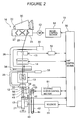
- Figure 2 is a front view showing a general configuration of the winder unit 10.
- the winder unit 10 shown in Figures 1 and 2 , winds a yarn 20 unwound from a yarn supplying bobbin 21, around a winding bobbin 22 while traversing the yarn 20, to form a package 30 of a predetermined length and a predetermined shape.
- the automatic winder according to the present embodiment comprises a plurality of winder units 10 arranged in a row and a frame control device (not shown in the drawings) located at one end of the arrangement of the winder units in the direction of the arrangement.
- Each of the winder unit 10 comprises a unit frame 11 ( Figure 1 ) provided on one lateral side thereof in a front view and a winding unit main body 16 provided on a side of the unit frame 11.
- the winding unit main body 16 comprises a cradle 23 configured to be able to hold the winding bobbin 22, and a takeup drum (traverse drum) 24 that traverses the yarn 20 while rotating the winding bobbin 22.
- the cradle 23 is configured to be swingable in a direction in which the cradle approaches or leaves the takeup drum 24.
- the package 30 contacts with the takeup drum 24 or leaves from the takeup drum 24.
- the takeup drum 24 is configured such that a spiral traverse groove 27 is formed in an outer peripheral surface of the takeup drum 24.
- the yarn 20 is traversed by the traverse groove 27.
- the cradle 23 comprises a liftup mechanism and a package brake mechanism (neither of the mechanisms are shown in the drawings).
- the liftup mechanism can elevate the cradle 23 to leave the package 30 from the takeup drum 24.
- the package brake mechanism is configured to stop rotation of the package 30 gripped by the cradle 23 simultaneously with the elevation of the cradle 23 by the liftup mechanism.
- the winding unit main body 16 is configured such that an unwinding assisting device 12, a tensioning device 13, a splicer device 14 as a yarn splicing device, and a clearer (yarn thickness detector) 15 are arranged in this order from the yarn supplying bobbin 21 side, in a yarn traveling path between the yarn supplying bobbin 21 and the takeup drum 24.
- the winder unit 10 comprises a magazine-type supply device 60 that supplies the yarn supplying bobbin 21.
- the illustration of the magazine-type supply device 60 is omitted in Figure 2 in order to illustrate the unwinding assisting device 12 in detail.
- the magazine-type supply device 60 comprises a magazine holding section 61 extending obliquely forward and upward from the bottom of the winder unit and a bobbin housing device 62 attached to the tip of the magazine holding device 61.
- the bobbin housing device 62 comprises a magazine pocket 63 having a plurality of housing holes formed therein so as to lie in a circular form.
- a supply bobbin 70 can be set in each of the housing holes in an inclined posture.
- the magazine pocket 63 can be intermittently driven by a motor (not shown in the drawings) so as to be rotationally fed.
- the intermittent driving and a control valve (not shown in the drawings) provided in the magazine pocket 63 enable the supply bobbins 70 to be dropped, one by one, onto a bobbin supply path (not shown in the drawings) provided in the magazine holding section 61.
- the supply bobbin 70 supplied to the bobbin supply path is guided to a yarn supplying bobbin holding section 71 while maintaining the inclined posture.
- the yarn supplying bobbin holding section 71 comprises a pivoting means (not shown in the drawings). Upon receiving the supply bobbin 70 from the bobbin supply path, the yarn supplying bobbin holding section 71 pivots so as to raise the supply bobbin 70 from an inclined posture to an upright posture. Thus, the supply bobbin 70 is appropriately supplied to the bottom of the winding unit main body 16 as the yarn supplying bobbin 21 to allow the winder unit 10 to perform a winding operation.
- the unwinding assisting device 12 assists in unwinding the yarn from the yarn supplying bobbin 21 by lowering a regulating member 40 covering a core tube of the yarn supplying bobbin 21, in conjunction with unwinding of the yarn from the yarn supplying bobbin 21.
- the regulating member 40 comes into contact with a balloon formed at the top of the yarn supplying bobbin 21 by the rotation and centrifugal force of the yarn unwound from the yarn supplying bobbin 21.
- the regulating member 40 applies an appropriate tension to the balloon to assist in unwinding the yarn.
- the unwinding assisting device 12 will be described below in detail.
- a kink preventer 17 is located in the vicinity of the unwinding assisting device 12 to prevent possible kink during the yarn splicing operation.
- the kink preventer 17 comprises a pivoting section and a brush section 31.
- the pivoting section is pivotably moved by a rotary solenoid 55 shown in Figure 2 .
- the pivoting section turns to cause the brush section 31 to abut against an upper end portion of the yarn supplying bobbin 21.
- an appropriate tension can be applied to the yarn to prevent kink.
- the tensioning device 13 applies a predetermined tension to the traveling yarn 20.
- the tensioning device 13 may be, for example, of a gate type in which movable comb teeth are arranged with respect to fixed comb teeth.
- the movable comb teeth can be pivotably moved by a rotary solenoid so as to engage with or disengage from the fixed teeth.
- the tensioning device 13 can apply the given tension to the yarn being wound, to improve the quantity of the package 30.
- the splicer device 14 splices a lower yarn on the yarn supplying bobbin 21 side and an upper yarn on the package 30 side when yarn cutting, yarn breakage, or the like occurs; the yarn cutting is performed by the clearer 15 detecting a yarn defect, and yarn breakage may occur during the unwinding of the yarn from the yarn supplying bobbin 21.
- the splicer device 14 may be of a mechanical type or may use a fluid such as compressed air.
- the clearer 15 is configured to use an appropriate sensor to detect the thickness of the yarn 20 in order to detect a defect. Furthermore, the clearer 15 is configured such that a signal from the sensor of the clearer 15 is processed by an analyzer 52 ( Figure 2 ) so that the clearer 15 can detect a yarn defect such as slab. The clearer 15 can also function as a sensor simply sensing whether or not the yarn 20 is present. A cutter is provided in the vicinity of the clearer 15 to immediately cut the yarn 20 when the clearer 15 detects a yarn defect.
- a first relay pipe 25 and a second relay pipe 26 are provided below and above the splicer device 14, respectively; the first relay pipe 25 catches and guides the lower yarn on the yarn supplying bobbin 21 side, and the second relay pipe 26 catches and guides the upper yarn on the package 30 side.
- a suction port 32 is formed at the tip of the first relay pipe 25 and a suction mouth 34 is provided at the tip of the second relay pipe 26.
- An appropriate negative pressure source is connected to each of the relay pipes 25, 26 to allow the suction port 32 and the suction mouth 34 to provide a suction stream.
- the suction port 32 of the first relay pipe 25 catches the lower yarn at a position shown in Figures 1 and 2 . Subsequently, the suction port 32 pivotably moves upward around a shaft 33 to guide the lower yarn to the splicer device 14. Furthermore, at almost the same time, the second relay pipe 26 pivotably moves upward from the illustrated position around a shaft 35. Thus, the upper yarn present on a surface of the package 30 reversed by a drum driving motor 53 is caught by the suction mouth 34. Subsequently, the second relay pipe 26 pivotably moves downward around the shaft 35 to guide the upper yarn to the splicer device 14.
- the yarn unwound from the yarn supplying bobbin 21 is wound around the winding bobbin 22 located downstream side of the splicer device 14.
- the winding bobbin 22 is driven by rotational driving of a winding drum 24 located opposite the winding bobbin 22.
- the winding drum 24 is coupled to an output shaft of the drum driving motor 53, and the operation of the drum driving motor 53 is controlled by a motor control section 54.
- the motor control section 54 is configured to receive an operation signal from a unit control section 50 to perform control such that the drum driving motor 53 is operated and stopped.
- the winding bobbin 22 is driven to wind the yarn 20 unwound from the yarn supplying bobbin 21, around the winding bobbin 22.
- the package 30 of a predetermined length can be formed.
- Figure 3 is a perspective view showing an essential part of the unwinding assisting device 12 according to the present embodiment.
- the unwinding assisting device 12 comprises a regulating member 40 shaped like a cylinder, a stepping motor 41 driving the regulating member 40, a belt member 42 that transmits the driving of the stepping motor 41 to the regulating member 40, and a second regulating member 56 located above the regulating member 40.
- the regulating member 40 is held at one end of a regulating member support plate 47 that can move slidably in a vertical direction along a guide shaft 45 located to extend in the vertical direction.
- a chase portion detecting sensor 46 is attached to the regulating member support plate 47.
- the chase portion detecting sensor 46 is configured as a non-contact distance sensor so as to be able to detect what is called a chase portion of the yarn supplying bobbin 21.
- the second regulating member 56 is shaped like a cylinder, and has an upper end fixed to the winder unit 10 by a mouthpiece 58 (not shown in Figure 3 ) or the like.
- the outer diameter of the second regulating member 56 is smaller than the inner diameter of the regulating member 40.
- the fixed side second regulating member 56 can be located so as to be inserted into the moved side regulating member 40.
- a throttling section 57 is provided below the second regulating member 56.
- the throttling section 57 has a hole smaller than the inner diameter of the second regulating member 56.
- the throttling section 57 is configured such that the yarn 20 unwound from the yarn supplying bobbin 21 passes through the hole.
- the distance from the throttling section 57 to the top of the yarn supplying bobbin 21 is set to be within the range of, for example, 10 to 20 millimeters.
- the throttling section 57 can regulate a balloon generated above the regulating member 40. This allows the winding operation to be appropriately performed under a given tension.
- the second regulating member 56 is not limited to the cylindrical shape.
- the shape of the second regulating member 56 can be appropriately changed provided that the second regulating member 56 has the throttling section 57.
- the second regulating member 56 can be configured as a metal plate folded member.
- the stepping motor 41 is located in the vicinity of an upper end of the guide shaft 45.
- a driving gear 43 is fixed to an output shaft of the stepping motor 41.
- a driven gear 44 is rotatably supported in the vicinity of a lower end of the guide shaft 45.
- An endless belt member 42 is wound around the driving gear 43 and the driven gear 44.
- the belt member 42 is configured as a toothed belt having teeth (not shown in the drawings) on an inner peripheral surface.
- the belt member 42 is located to extend elongately in the vertical direction so as to cover the range within which the regulating member 40 is elevated and lowered.
- the regulating member support plate 47 is fixed to an appropriate position on the belt member 42. In this configuration, the driving gear 43 rotates to drive the belt member 42 to enable elevating and lowering of the regulating member support plate 47 connected to the belt member 42.
- the stepping motor 41 is connected to a stepping motor control section 51, which outputs a driving pulse signal to the stepping motor 41 to drive the stepping motor 41. Furthermore, the stepping motor control section 51 is configured to be able to count the number of pulses transmitted to the stepping motor 41 and to store the count value.
- the stepping motor control section 51 is connected to the unit control section 50 to allow control of such sections as the splicer device 14 and the clearer 15 to be interlocked with control of the unwinding assisting device 12.
- the stepping motor 41 is configured to step out when at least a given load is imposed on the output shaft.
- the unit control section 50 controls the stepping motor 41 via the stepping motor control section 51 to control the position of the regulating member 40 while using the chase portion detecting sensor 46 to determine the position of the chase portion of the yarn supplying bobbin 21. That is, the position of the chase portion lowers as the yarn is unwound from the yarn supplying bobbin 21.
- the chase portion detecting sensor 46 detects the position of the chase portion to drive the stepping motor 41 to lower the regulating member 40 in conjunction with the lowering of the chase portion.
- the above-described yarn splicing operation is performed when, for example, the yarn is broke during the unwinding of the yarn from the yarn supplying bobbin 21, the clearer 15 finds a yarn defect to cut the yarn with the cutter, or a new yarn supplying bobbin 21 is supplied.
- the unit control section 50 sends a signal to the stepping motor control section 51 to elevate the regulating member 40 to the position of the uppermost end thereof.
- the kink preventer 17 contacts with the brush section 31 with the vicinity of the core tube of the yarn supplying bobbin 21 to apply tension to the yarn, so that kink can be prevented.
- the regulating member 40 is lowered to the original position to recover the condition in which a balloon generated during yarn unwinding can be controlled again.
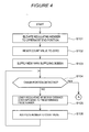
- Figures 4 and 5 are flowcharts showing the control of the unwinding assisting device 12.
- the stepping motor control unit 51 receives an instruction from the unit control section 50 to drive the stepping motor 41.
- the regulating member 40 of the unwinding assisting device 12 is thus elevated to the uppermost end of an elevating and lowering stroke (S101).
- the position of the uppermost end is an origin position.
- the arrival of the regulating member 40 at the uppermost end position can be detected by an origin sensor (not shown in the drawings) composed of, for example, a limit switch.
- the stepping motor control section 51 resets a variable for storing the count value to zero (S102).
- a new yarn supplying bobbin 21 is supplied (S103). Then, the unit control section 50 immediately checks whether or not the chase portion detecting sensor 46 has detected the chase portion of the yarn supplying bobbin 21 (S104). Where the chase portion has not been detected, a predetermined number of driving pulses are transmitted to the stepping motor 41 to lower the regulating member 40 (S105). Then, the number of transmitted driving pulses is added to the count value (S106). Subsequently, the process returns to S104 to check again whether or not the chase portion detecting sensor 46 has detected the chase portion.
- the loop from S104 to S106 allows the regulating member 40 to lower until the chase portion detecting sensor 46 detects the chase portion and also enables the storage of the count value for driving pulses transmitted to the stepping motor 41 for the lowering.
- the process shifts to S107 in Figure 5 to start the winding operation. Even after the winding operation to the package 30 is actually started, the unit control section 50 checks whether or not the chase portion detecting sensor 46 has detected the chase portion of the yarn supplying bobbin 21 (S108). When the yarn is unwound from the yarn supplying bobbin 21 to lower the chase portion to prevent the chase portion detecting sensor 46 from detecting the chase portion, the stepping motor control section 51 transmits a predetermined number of driving pulses to the stepping motor 41 on the basis of a signal from the unit control section 50. The regulating member 40 is thus lowered (S109). Furthermore, the stepping motor control section 51 adds the number of transmitted driving pulses to the count value (S110).
- the unit control section 50 checks whether or not yarn cutting or breakage has occurred in the winder unit 10 (S111). That is, the unit control section 50 checks, on the basis of a signal from the clearer 15, whether or not the yarn has been broken during the unwinding of the yarn from the yarn supplying bobbin 21 or the clearer 15 has found a yarn defect to cut the yarn with the cutter.
- the unit control section 50 immediately elevates the regulating member 40 to the uppermost end (the above-described origin position) (S112) and starts the yarn splicing operation by driving the relay pipes 25, 26, the splicer device 14, and the like (S113). Since the regulating member 40 has been elevated to the uppermost end, the brush section 31 of the kink preventer 17 can be smoothly contacted with the upper end of the core tube of the yarn supplying bobbin 21 during the yarn splicing operation to prevent possible kink in the yarn.
- the unit control section 50 and the stepping motor control section 51 stand by until the yarn splicing operation is completed (S114). Once the yarn splicing operation is completed, the stepping motor control section 51 transmits driving pulses the number of which is equal to the stored count value, to the stepping motor 41. The regulating member 40 is thus lowered to the position where the yarn breakage or cutting has occurred (S115). Where the unit control section determines in S111 that neither yarn breakage nor cutting has occurred, the processing in S112 to S116 is not executed.
- the unit control section 50 checks whether or not the yarn winding has been completed (S117). Where the winding has not been completed, the process returns to S108. Where the winding has been completed, the process is terminated.
- the above-described flow enables the regulating member 40 to be gradually lowered smoothly following the lowering of the chase portion of the yarn supplying bobbin 21, while repeating the operation of retracting the regulating member 40 when yarn breakage or cutting occurs and returning the regulating member 40 to the original position after yarn splicing.
- the regulating member 40 may be configured so as to stop further lowering upon reaching a predetermined position, regardless of whether or not the chase portion has been detected.
- the unwinding assisting device 12 for the winder comprises the regulating member 40, which regulates the balloon generated when the yarn 20 is unwound from the yarn supplying bobbin 21, and the elevating and lowering means for elevating and lowering the regulating means 40.
- the elevating and lowering means comprises the stepping motor 41 and the belt member 42, which transmits the driving of the stepping motor 41.
- This configuration allows the position of the regulating member 40 to be precisely controlled in very small incremental steps in pulse unit (in an almost nonstep manner) by performing pulse control on the stepping motor 41. Furthermore, the configuration is such that the driving force of the stepping motor 41 is transmitted to the regulating member 40 by the relatively light belt member 42. This enables a reduction in a possible inertia force during elevating or lowering of the regulating member 40. Acceleration and deceleration performance is thus improved. Therefore, very precise balloon control can be performed, and a possible excessive impact can be prevented where the regulating member 40 is elevated and lowered at a high speed.
- the weight of the elevating and lowering components can be reduced to allow the regulating member 40 to elevate and lower smoothly.
- electric wiring to the stepping motor 41 and the like can be simplified.
- the impact is absorbed by the belt member 42. A possible excessive impact can thus be prevented from being transmitted to the stepping motor 41 side to damage the stepping motor 41.
- a step-out function of the stepping motor 41 itself can also absorb the impact, thus preventing the stepping motor 41 from being damaged.
- the elevating and lowering means is composed of the stepping motor 41 and the belt member 42, and thus has a simple configuration. This enables a reduction in the size of the device and in costs. Additionally, where the elevating and lowering stroke of the regulating member 40 is to be changed, the changing operation can be easily performed by making a minor change to the configuration, for example, replacing the belt member 42 with a longer one. Furthermore, the belt member 42 basically does not require lubrication, enabling a reduction in the number of maintenance operations required. Moreover, possible fiber dust resulting from yarn unwinding or the like can be prevented from adhering to lubricating oil to cause the unwinding assisting device 12 to fail.
- the belt member 42 is a toothed belt.
- the toothed belt can transmit the driving force of the stepping motor 41 without slippage.
- required energy can be appropriately saved, and the elevating and lowering of the regulating member 40 can be further precisely and smoothly controlled.
- the winder unit 10 used in the automatic winder according to the present embodiment, comprises the above-described unwinding assisting device 12, the splicer device 14, which performs the yarn splicing operation, and the stepping motor control section 51, which counts the number of pulses transmitted to the stepping motor 41.
- the winder unit 10 also comprises the unit control section 50, which controls the regulating means 40 so that when the yarn unwound from the yarn supplying bobbin 21 is broken or cut, the regulating member 40 is retracted.
- the unit control section 50 controls the regulating member 40 so that when the yarn splicing operation by the splicer device 14 is completed, the regulating member 40 is returned to the original position on the basis of the result of counting of the pulse number by the stepping motor control section 51.
- the regulating member 40 can be quickly and accurately moved to the position where the yarn breakage or cutting has occurred, on the basis of the stored count value for the pulse number. This allows the yarn winding operation to be quickly resumed, enabling a reduction in the cycle time of all the operation steps including the yarn splicing operation.
- the toothed belt is used as the belt member 42.
- the shape of the belt can be appropriately changed; for example, a flat belt or a V belt can be used instead of the above-described arrangement.
- the number of pulses is counted which is required to move the regulating member 40 from the uppermost position to the position corresponding to the point in time of yarn breakage or cutting.
- the number of pulses may be counted which is required to retract the regulating member 40 to the uppermost position from the position corresponding to the point in time of the yarn breakage or cutting so that after the yarn splicing operation, the regulating member 40 can be lowered by a distance corresponding to the pulse number indicated by the count value.
- the stepping motor control section 51 functions as count means.
- the configuration of the count means may be appropriately changed; for example, the above-described arrangement may be changed such that the unit control section 50 functions as count means.
- the winder unit 10 is supplied with the yarn supplying bobbin 21 by the magazine-type supply device 60.
- the present invention is not limited to this arrangement.
- the arrangement may be changed such that the yarn supplying bobbin 21 is supplied to the winder unit 10 by conveying a tray with the yarn supplying bobbin 21 set thereon along an appropriate path.
Abstract
Description
- The present invention relates to an automatic winder, and specifically, to an unwinding assisting device that regulates a balloon generated when a yarn is unwound from a yarn supplying bobbin.
- An automatic winder is conventionally known which is configured to regulate a balloon generated when a yarn is unwound from a yarn supplying bobbin. The unwinding assisting device lowers a regulating member as an unwinding point of the yarn from the yarn supplying bobbin lowers. The unwinding assisting device thus maintains the distance from the unwinding point constant to control formation of the balloon.
- An unwinding assisting device of this kind often comprises a sensor that senses the position of an upper end of the yarn to be unwound, and an elevating and lowering means for elevating and lowering the regulating means. The unwinding assisting device is further configured to control the elevating and lowering means such as an air cylinder or a stepping motor as the upper end position of the yarn lowers to lower the regulating member in conjunction with the lowering of the upper end position.
- The Unexamined Japanese Patent Application Publication (
Tokkai-Hei) No. 8-198520 Tokkai-Hei) No. 8-198520 Tokkai-Hei) No. 8-198520 - However, where the above-described air cylinder is used as an elevating and lowering means for the regulating member, the use of air pressure makes it difficult to smoothly and precisely control the elevating and lowering of the regulating member in conjunction with movement of the unwinding point.
- Furthermore, in the automatic winder, where yarn breakage or the like occurs and the regulating member is retracted for a yarn splicing operation, then after the yarn splicing operation is completed, the regulating member is desirably returned quickly to the original position to allow a winding operation to be resumed. However, the air cylinder is configured to drive forward and backward a cylinder rod or the like, which is relatively heavy. Thus, when the air cylinder returns to the original position at an excessively high speed, a strong inertia force is generated to impact related components of the device. This may cause a failure or the like. Moreover, owing to the configuration of the air cylinder device, an installation space for the air cylinder requires a length almost double the moving distance of the regulating member. Consequently, reducing the size of the device is difficult.
- Furthermore, the Unexamined Japanese Patent Application Publication (
Tokkai-Hei) No. 8-198520 Tokkai-Hei) No. 8-198520 - Furthermore, where the rack pinion mechanism is used to move the elevating and lowering guide up and down, then since a gear is configured with possible backlash taken into account, the rack pinion mechanism is likely to be shaky. Thus, precise positioning of the elevating and lowering guide is difficult. Moreover, where the stepping motor side is fixed so that the elevating and lowering guide is elevated and lowered together with a rack, then since a space for rack movement requires a length almost double the moving distance of the elevating and lowering guide, a sufficient size reduction is impossible. Furthermore, where an area in which the rack and the pinion engage with each other is lubricated, possible fiber dust resulting from yarn unwinding or the like is likely to adhere to the area. Accumulation of the fiber dust may cause a failure. Moreover, much time and effort is required for a maintenance operation of removing the fiber dust firmly attached to the lubricated area.
- The present invention has been made in view of these circumstances. An object of the present invention is to provide an unwinding assisting device for an automatic winder which enables fine-tuning of elevating and lowering of the regulating member and which can prevent a possible impact during elevating or lowering.
- The problems to be solved by the present invention have been described. Means for solving the problems and the effects thereof will be described.
- A first aspect of the present invention provides an unwinding assisting device for an automatic winder configured as described below. That is, the unwinding assisting device comprises a regulating member that regulates a balloon generated when a yarn is unwound from a yarn supplying bobbin and an elevating and lowering means for elevating and lowering the regulating means. The elevating and lowering means comprises a stepping motor and a belt member that transmits driving of the stepping motor.
- Thus, the position of the regulating member can be precisely controlled in very small incremental steps in pulse unit (in an almost nonstep manner) by performing pulse control on the stepping motor. Furthermore, the configuration is such that the driving force of the stepping motor is transmitted to the regulating member by a relatively light belt member. This enables a reduction in a possible inertia force during elevating or lowering of the regulating member. Acceleration and deceleration performance is thus improved. Therefore, very precise balloon control can be performed, and a possible excessive impact can be prevented where the regulating member is elevated and lowered at a high speed. Moreover, where a certain impact occurs on the regulating member, the impact is absorbed by the belt member. A possible excessive impact can thus be prevented from being transmitted to the stepping motor side to damage the stepping motor. Moreover, a step-out function of the stepping motor itself can also absorb the impact, thus preventing the stepping motor from being damaged. Furthermore, the elevating and lowering means is composed of the stepping motor and the belt member, and thus has a simple configuration. This enables a reduction in the size of the device and in costs. Additionally, where the elevating and lowering stroke of the regulating member is to be changed, the changing operation can be easily performed by making a minor change to the configuration.
- In the unwinding assisting device for the automatic winder, the belt member is preferably a toothed belt.
- The toothed belt can transmit the driving force of the stepping motor without slippage. Thus, required energy can be appropriately saved, and the elevating and lowering of the regulating member can be further precisely and smoothly controlled.
- A second aspect of the present invention provides an automatic winder configured as follows. That is, the automatic winder comprises the above-described unwinding assisting device, a yarn splicing device that performs a yarn splicing operation, a count means for counting number of pulses transmitted to the stepping motor, and a control section. The control section controls the regulating means so that when a yarn unwound from a yarn supplying bobbin is broken or cut, the regulating member is retracted. Furthermore, the control section controls the regulating member so that when the yarn splicing operation by the yarn splicing device is completed, the regulating member is returned to an original position on the basis of a count result from the count means.
- Thus, where yarn breakage or cutting occurs and the regulating member is retracted, after the yarn splicing operation is performed, the regulating member can be quickly and accurately moved to the position where the yarn breakage or cutting has occurred, on the basis of a stored count value for the pulse number. This allows the yarn winding operation to be quickly resumed, enabling a reduction in the cycle time of all the operation steps including the yarn splicing operation.
- Other features, elements, processes, steps, characteristics and advantages of the present invention will become more apparent from the following detailed description of preferred embodiments of the present invention with reference to the attached drawings.
-
-
Figure 1 is a side view of a winder unit provided in an automatic winder according to an embodiment of the present invention. -
Figure 2 is a front view showing a general configuration of the winder unit. -
Figure 3 is a perspective view of an essential part of an unwinding assisting device. -
Figure 4 is a flowchart showing the former half of control of a regulating member. -
Figure 5 is a flowchart showing the latter half of the control of the regulating member. - A preferred embodiment of the present invention will be described below with reference to the drawings.
Figure 1 is a side view of awinder unit 10 provided in an automatic winder according to an embodiment of the present invention.
Figure 2 is a front view showing a general configuration of thewinder unit 10. - The
winder unit 10, shown inFigures 1 and2 , winds ayarn 20 unwound from ayarn supplying bobbin 21, around a windingbobbin 22 while traversing theyarn 20, to form apackage 30 of a predetermined length and a predetermined shape. The automatic winder according to the present embodiment comprises a plurality ofwinder units 10 arranged in a row and a frame control device (not shown in the drawings) located at one end of the arrangement of the winder units in the direction of the arrangement. - Each of the
winder unit 10 comprises a unit frame 11 (Figure 1 ) provided on one lateral side thereof in a front view and a winding unitmain body 16 provided on a side of theunit frame 11. - The winding unit
main body 16 comprises acradle 23 configured to be able to hold the windingbobbin 22, and a takeup drum (traverse drum) 24 that traverses theyarn 20 while rotating the windingbobbin 22. Thecradle 23 is configured to be swingable in a direction in which the cradle approaches or leaves thetakeup drum 24. Thus, thepackage 30 contacts with thetakeup drum 24 or leaves from thetakeup drum 24. As shown inFigure 2 , thetakeup drum 24 is configured such that aspiral traverse groove 27 is formed in an outer peripheral surface of thetakeup drum 24. Thus, theyarn 20 is traversed by thetraverse groove 27. - The
cradle 23 comprises a liftup mechanism and a package brake mechanism (neither of the mechanisms are shown in the drawings). When yarn breakage occurs, the liftup mechanism can elevate thecradle 23 to leave thepackage 30 from thetakeup drum 24. The package brake mechanism is configured to stop rotation of thepackage 30 gripped by thecradle 23 simultaneously with the elevation of thecradle 23 by the liftup mechanism. - The winding unit
main body 16 is configured such that anunwinding assisting device 12, atensioning device 13, asplicer device 14 as a yarn splicing device, and a clearer (yarn thickness detector) 15 are arranged in this order from theyarn supplying bobbin 21 side, in a yarn traveling path between theyarn supplying bobbin 21 and thetakeup drum 24. - As shown in
Figure 1 , thewinder unit 10 comprises a magazine-type supply device 60 that supplies theyarn supplying bobbin 21. The illustration of the magazine-type supply device 60 is omitted inFigure 2 in order to illustrate theunwinding assisting device 12 in detail. As shown inFigure 1 , the magazine-type supply device 60 comprises amagazine holding section 61 extending obliquely forward and upward from the bottom of the winder unit and abobbin housing device 62 attached to the tip of themagazine holding device 61. - The
bobbin housing device 62 comprises amagazine pocket 63 having a plurality of housing holes formed therein so as to lie in a circular form. Asupply bobbin 70 can be set in each of the housing holes in an inclined posture. Themagazine pocket 63 can be intermittently driven by a motor (not shown in the drawings) so as to be rotationally fed. The intermittent driving and a control valve (not shown in the drawings) provided in themagazine pocket 63 enable thesupply bobbins 70 to be dropped, one by one, onto a bobbin supply path (not shown in the drawings) provided in themagazine holding section 61. Thesupply bobbin 70 supplied to the bobbin supply path is guided to a yarn supplyingbobbin holding section 71 while maintaining the inclined posture. - The yarn supplying
bobbin holding section 71 comprises a pivoting means (not shown in the drawings). Upon receiving thesupply bobbin 70 from the bobbin supply path, the yarn supplyingbobbin holding section 71 pivots so as to raise thesupply bobbin 70 from an inclined posture to an upright posture. Thus, thesupply bobbin 70 is appropriately supplied to the bottom of the winding unitmain body 16 as theyarn supplying bobbin 21 to allow thewinder unit 10 to perform a winding operation. - The unwinding assisting
device 12 assists in unwinding the yarn from theyarn supplying bobbin 21 by lowering a regulatingmember 40 covering a core tube of theyarn supplying bobbin 21, in conjunction with unwinding of the yarn from theyarn supplying bobbin 21. The regulatingmember 40 comes into contact with a balloon formed at the top of theyarn supplying bobbin 21 by the rotation and centrifugal force of the yarn unwound from theyarn supplying bobbin 21. Thus, the regulatingmember 40 applies an appropriate tension to the balloon to assist in unwinding the yarn. The unwinding assistingdevice 12 will be described below in detail. - Furthermore, a
kink preventer 17 is located in the vicinity of theunwinding assisting device 12 to prevent possible kink during the yarn splicing operation. Thekink preventer 17 comprises a pivoting section and abrush section 31.
The pivoting section is pivotably moved by arotary solenoid 55 shown inFigure 2 . During the yarn splicing operation, with the above-describedunwinding assisting device 12 retracted to the position of the uppermost end thereof, the pivoting section turns to cause thebrush section 31 to abut against an upper end portion of theyarn supplying bobbin 21. Thus, during the yarn splicing operation, an appropriate tension can be applied to the yarn to prevent kink. - The
tensioning device 13 applies a predetermined tension to the travelingyarn 20. Thetensioning device 13 may be, for example, of a gate type in which movable comb teeth are arranged with respect to fixed comb teeth. The movable comb teeth can be pivotably moved by a rotary solenoid so as to engage with or disengage from the fixed teeth. Thetensioning device 13 can apply the given tension to the yarn being wound, to improve the quantity of thepackage 30. - The
splicer device 14 splices a lower yarn on theyarn supplying bobbin 21 side and an upper yarn on thepackage 30 side when yarn cutting, yarn breakage, or the like occurs; the yarn cutting is performed by the clearer 15 detecting a yarn defect, and yarn breakage may occur during the unwinding of the yarn from theyarn supplying bobbin 21. For example, thesplicer device 14 may be of a mechanical type or may use a fluid such as compressed air. - The clearer 15 is configured to use an appropriate sensor to detect the thickness of the
yarn 20 in order to detect a defect. Furthermore, the clearer 15 is configured such that a signal from the sensor of the clearer 15 is processed by an analyzer 52 (Figure 2 ) so that the clearer 15 can detect a yarn defect such as slab. The clearer 15 can also function as a sensor simply sensing whether or not theyarn 20 is present. A cutter is provided in the vicinity of the clearer 15 to immediately cut theyarn 20 when the clearer 15 detects a yarn defect. - A
first relay pipe 25 and asecond relay pipe 26 are provided below and above thesplicer device 14, respectively; thefirst relay pipe 25 catches and guides the lower yarn on theyarn supplying bobbin 21 side, and thesecond relay pipe 26 catches and guides the upper yarn on thepackage 30 side. Asuction port 32 is formed at the tip of thefirst relay pipe 25 and asuction mouth 34 is provided at the tip of thesecond relay pipe 26. An appropriate negative pressure source is connected to each of therelay pipes suction port 32 and thesuction mouth 34 to provide a suction stream. - In this configuration, when yarn cutting or yarn breakage occurs, the
suction port 32 of thefirst relay pipe 25 catches the lower yarn at a position shown inFigures 1 and2 . Subsequently, thesuction port 32 pivotably moves upward around ashaft 33 to guide the lower yarn to thesplicer device 14. Furthermore, at almost the same time, thesecond relay pipe 26 pivotably moves upward from the illustrated position around ashaft 35. Thus, the upper yarn present on a surface of thepackage 30 reversed by adrum driving motor 53 is caught by thesuction mouth 34. Subsequently, thesecond relay pipe 26 pivotably moves downward around theshaft 35 to guide the upper yarn to thesplicer device 14. - The yarn unwound from the
yarn supplying bobbin 21 is wound around the windingbobbin 22 located downstream side of thesplicer device 14. The windingbobbin 22 is driven by rotational driving of a windingdrum 24 located opposite the windingbobbin 22. As shown inFigure 2 , the windingdrum 24 is coupled to an output shaft of thedrum driving motor 53, and the operation of thedrum driving motor 53 is controlled by amotor control section 54. Themotor control section 54 is configured to receive an operation signal from aunit control section 50 to perform control such that thedrum driving motor 53 is operated and stopped. - In the above-described configuration, when the bobbin from the magazine-
type supply device 60 is supplied to the yarn supplying side, the windingbobbin 22 is driven to wind theyarn 20 unwound from theyarn supplying bobbin 21, around the windingbobbin 22. Thus, thepackage 30 of a predetermined length can be formed. - Now, the unwinding assisting
device 12 according to the present embodiment will be described with reference toFigure 3. Figure 3 is a perspective view showing an essential part of theunwinding assisting device 12 according to the present embodiment. - As shown in
Figure 3 , the unwinding assistingdevice 12 comprises a regulatingmember 40 shaped like a cylinder, a steppingmotor 41 driving the regulatingmember 40, abelt member 42 that transmits the driving of the steppingmotor 41 to the regulatingmember 40, and a second regulatingmember 56 located above the regulatingmember 40. The regulatingmember 40 is held at one end of a regulatingmember support plate 47 that can move slidably in a vertical direction along aguide shaft 45 located to extend in the vertical direction. Moreover, a chaseportion detecting sensor 46 is attached to the regulatingmember support plate 47. The chaseportion detecting sensor 46 is configured as a non-contact distance sensor so as to be able to detect what is called a chase portion of theyarn supplying bobbin 21. - The
second regulating member 56 is shaped like a cylinder, and has an upper end fixed to thewinder unit 10 by a mouthpiece 58 (not shown inFigure 3 ) or the like. The outer diameter of the second regulatingmember 56 is smaller than the inner diameter of the regulatingmember 40. Thus, the fixed side second regulatingmember 56 can be located so as to be inserted into the movedside regulating member 40. Furthermore, athrottling section 57 is provided below the second regulatingmember 56. The throttlingsection 57 has a hole smaller than the inner diameter of the second regulatingmember 56. The throttlingsection 57 is configured such that theyarn 20 unwound from theyarn supplying bobbin 21 passes through the hole. The distance from the throttlingsection 57 to the top of theyarn supplying bobbin 21 is set to be within the range of, for example, 10 to 20 millimeters. The throttlingsection 57 can regulate a balloon generated above the regulatingmember 40. This allows the winding operation to be appropriately performed under a given tension. - The
second regulating member 56 is not limited to the cylindrical shape. The shape of the second regulatingmember 56 can be appropriately changed provided that the second regulatingmember 56 has thethrottling section 57. For example, the second regulatingmember 56 can be configured as a metal plate folded member. - The stepping
motor 41 is located in the vicinity of an upper end of theguide shaft 45. Adriving gear 43 is fixed to an output shaft of the steppingmotor 41. On the other hand, a drivengear 44 is rotatably supported in the vicinity of a lower end of theguide shaft 45. Anendless belt member 42 is wound around thedriving gear 43 and the drivengear 44. Thebelt member 42 is configured as a toothed belt having teeth (not shown in the drawings) on an inner peripheral surface. - The
belt member 42 is located to extend elongately in the vertical direction so as to cover the range within which the regulatingmember 40 is elevated and lowered. The regulatingmember support plate 47 is fixed to an appropriate position on thebelt member 42. In this configuration, thedriving gear 43 rotates to drive thebelt member 42 to enable elevating and lowering of the regulatingmember support plate 47 connected to thebelt member 42. - As shown in
Figure 2 , the steppingmotor 41 is connected to a steppingmotor control section 51, which outputs a driving pulse signal to the steppingmotor 41 to drive the steppingmotor 41. Furthermore, the steppingmotor control section 51 is configured to be able to count the number of pulses transmitted to the steppingmotor 41 and to store the count value. The steppingmotor control section 51 is connected to theunit control section 50 to allow control of such sections as thesplicer device 14 and the clearer 15 to be interlocked with control of theunwinding assisting device 12. The steppingmotor 41 is configured to step out when at least a given load is imposed on the output shaft. - The
unit control section 50 controls the steppingmotor 41 via the steppingmotor control section 51 to control the position of the regulatingmember 40 while using the chaseportion detecting sensor 46 to determine the position of the chase portion of theyarn supplying bobbin 21. That is, the position of the chase portion lowers as the yarn is unwound from theyarn supplying bobbin 21. The chaseportion detecting sensor 46 detects the position of the chase portion to drive the steppingmotor 41 to lower the regulatingmember 40 in conjunction with the lowering of the chase portion. - Furthermore, the above-described yarn splicing operation is performed when, for example, the yarn is broke during the unwinding of the yarn from the
yarn supplying bobbin 21, the clearer 15 finds a yarn defect to cut the yarn with the cutter, or a newyarn supplying bobbin 21 is supplied. For the yarn splicing, theunit control section 50 sends a signal to the steppingmotor control section 51 to elevate the regulatingmember 40 to the position of the uppermost end thereof. Thus, thekink preventer 17 contacts with thebrush section 31 with the vicinity of the core tube of theyarn supplying bobbin 21 to apply tension to the yarn, so that kink can be prevented. Then, to complete the yarn splicing operation and then to resume winding, the regulatingmember 40 is lowered to the original position to recover the condition in which a balloon generated during yarn unwinding can be controlled again. - Now, the control of the
unwinding assisting device 12 will be described in detail with reference toFigures 4 and5 .Figures 4 and5 are flowcharts showing the control of theunwinding assisting device 12. - As shown in
Figure 4 , when the control flow is started, the steppingmotor control unit 51 receives an instruction from theunit control section 50 to drive the steppingmotor 41. The regulatingmember 40 of theunwinding assisting device 12 is thus elevated to the uppermost end of an elevating and lowering stroke (S101). The position of the uppermost end is an origin position. The arrival of the regulatingmember 40 at the uppermost end position can be detected by an origin sensor (not shown in the drawings) composed of, for example, a limit switch. When the elevation of the regulatingmember 40 is completed, the steppingmotor control section 51 resets a variable for storing the count value to zero (S102). - After the above-described initialization process, a new
yarn supplying bobbin 21 is supplied (S103). Then, theunit control section 50 immediately checks whether or not the chaseportion detecting sensor 46 has detected the chase portion of the yarn supplying bobbin 21 (S104). Where the chase portion has not been detected, a predetermined number of driving pulses are transmitted to the steppingmotor 41 to lower the regulating member 40 (S105). Then, the number of transmitted driving pulses is added to the count value (S106). Subsequently, the process returns to S104 to check again whether or not the chaseportion detecting sensor 46 has detected the chase portion. - The loop from S104 to S106 allows the regulating
member 40 to lower until the chaseportion detecting sensor 46 detects the chase portion and also enables the storage of the count value for driving pulses transmitted to the steppingmotor 41 for the lowering. - When the
unit control section 50 determines in S104 that the chase portion has been detected, the process shifts to S107 inFigure 5 to start the winding operation. Even after the winding operation to thepackage 30 is actually started, theunit control section 50 checks whether or not the chaseportion detecting sensor 46 has detected the chase portion of the yarn supplying bobbin 21 (S108). When the yarn is unwound from theyarn supplying bobbin 21 to lower the chase portion to prevent the chaseportion detecting sensor 46 from detecting the chase portion, the steppingmotor control section 51 transmits a predetermined number of driving pulses to the steppingmotor 41 on the basis of a signal from theunit control section 50. The regulatingmember 40 is thus lowered (S109). Furthermore, the steppingmotor control section 51 adds the number of transmitted driving pulses to the count value (S110). - Here, as shown in the processing in S105, S106, S109, and S110, according to the present embodiment, every time the regulating
member 40 is lowered, a process is executed which adds the number of driving pulses transmitted to the steppingmotor 41 for the lowering. Therefore, by lowering the regulatingmember 40 from the above-described uppermost end position by a distance corresponding to the number of pulses indicated by the count value, the current position of the regulatingmember 40 can be reproduced. - Furthermore, in parallel with the above-described process of monitoring the chase portion (the process of moving the regulating member 40), the
unit control section 50 checks whether or not yarn cutting or breakage has occurred in the winder unit 10 (S111). That is, theunit control section 50 checks, on the basis of a signal from the clearer 15, whether or not the yarn has been broken during the unwinding of the yarn from theyarn supplying bobbin 21 or the clearer 15 has found a yarn defect to cut the yarn with the cutter. - Where yarn breakage or cutting has occurred, the
unit control section 50 immediately elevates the regulatingmember 40 to the uppermost end (the above-described origin position) (S112) and starts the yarn splicing operation by driving therelay pipes splicer device 14, and the like (S113). Since the regulatingmember 40 has been elevated to the uppermost end, thebrush section 31 of thekink preventer 17 can be smoothly contacted with the upper end of the core tube of theyarn supplying bobbin 21 during the yarn splicing operation to prevent possible kink in the yarn. - Subsequently, the
unit control section 50 and the steppingmotor control section 51 stand by until the yarn splicing operation is completed (S114). Once the yarn splicing operation is completed, the steppingmotor control section 51 transmits driving pulses the number of which is equal to the stored count value, to the steppingmotor 41. The regulatingmember 40 is thus lowered to the position where the yarn breakage or cutting has occurred (S115). Where the unit control section determines in S111 that neither yarn breakage nor cutting has occurred, the processing in S112 to S116 is not executed. - Then, the
unit control section 50 checks whether or not the yarn winding has been completed (S117). Where the winding has not been completed, the process returns to S108. Where the winding has been completed, the process is terminated. The above-described flow enables the regulatingmember 40 to be gradually lowered smoothly following the lowering of the chase portion of theyarn supplying bobbin 21, while repeating the operation of retracting the regulatingmember 40 when yarn breakage or cutting occurs and returning the regulatingmember 40 to the original position after yarn splicing. The regulatingmember 40 may be configured so as to stop further lowering upon reaching a predetermined position, regardless of whether or not the chase portion has been detected. - As described above, the unwinding assisting
device 12 for the winder according to the present embodiment comprises the regulatingmember 40, which regulates the balloon generated when theyarn 20 is unwound from theyarn supplying bobbin 21, and the elevating and lowering means for elevating and lowering the regulating means 40. The elevating and lowering means comprises the steppingmotor 41 and thebelt member 42, which transmits the driving of the steppingmotor 41. - This configuration allows the position of the regulating
member 40 to be precisely controlled in very small incremental steps in pulse unit (in an almost nonstep manner) by performing pulse control on the steppingmotor 41. Furthermore, the configuration is such that the driving force of the steppingmotor 41 is transmitted to the regulatingmember 40 by the relativelylight belt member 42. This enables a reduction in a possible inertia force during elevating or lowering of the regulatingmember 40. Acceleration and deceleration performance is thus improved. Therefore, very precise balloon control can be performed, and a possible excessive impact can be prevented where the regulatingmember 40 is elevated and lowered at a high speed. Furthermore, where the steppingmotor 41 is installed (on the fixed side) so as not to move up and down, the weight of the elevating and lowering components can be reduced to allow the regulatingmember 40 to elevate and lower smoothly. Additionally, electric wiring to the steppingmotor 41 and the like can be simplified. Moreover, where an impact occurs on the regulatingmember 40 for any reason such as collision against another member, the impact is absorbed by thebelt member 42. A possible excessive impact can thus be prevented from being transmitted to the steppingmotor 41 side to damage the steppingmotor 41. Moreover, a step-out function of the steppingmotor 41 itself can also absorb the impact, thus preventing the steppingmotor 41 from being damaged. Furthermore, the elevating and lowering means is composed of the steppingmotor 41 and thebelt member 42, and thus has a simple configuration. This enables a reduction in the size of the device and in costs. Additionally, where the elevating and lowering stroke of the regulatingmember 40 is to be changed, the changing operation can be easily performed by making a minor change to the configuration, for example, replacing thebelt member 42 with a longer one. Furthermore, thebelt member 42 basically does not require lubrication, enabling a reduction in the number of maintenance operations required. Moreover, possible fiber dust resulting from yarn unwinding or the like can be prevented from adhering to lubricating oil to cause theunwinding assisting device 12 to fail. - Furthermore, in the
unwinding assisting device 12 according to the present embodiment, thebelt member 42 is a toothed belt. - The toothed belt can transmit the driving force of the stepping
motor 41 without slippage. Thus, required energy can be appropriately saved, and the elevating and lowering of the regulatingmember 40 can be further precisely and smoothly controlled. - Furthermore, the
winder unit 10, used in the automatic winder according to the present embodiment, comprises the above-describedunwinding assisting device 12, thesplicer device 14, which performs the yarn splicing operation, and the steppingmotor control section 51, which counts the number of pulses transmitted to the steppingmotor 41. Thewinder unit 10 also comprises theunit control section 50, which controls the regulating means 40 so that when the yarn unwound from theyarn supplying bobbin 21 is broken or cut, the regulatingmember 40 is retracted. Furthermore, theunit control section 50 controls the regulatingmember 40 so that when the yarn splicing operation by thesplicer device 14 is completed, the regulatingmember 40 is returned to the original position on the basis of the result of counting of the pulse number by the steppingmotor control section 51. - Thus, where yarn breakage or cutting occurs and the regulating
member 40 is retracted, after the yarn splicing operation is performed, the regulatingmember 40 can be quickly and accurately moved to the position where the yarn breakage or cutting has occurred, on the basis of the stored count value for the pulse number. This allows the yarn winding operation to be quickly resumed, enabling a reduction in the cycle time of all the operation steps including the yarn splicing operation. - The preferred embodiment of the present invention has been described above. However, the above-described configuration can further be configured as described below.
- In the above-described embodiment, the toothed belt is used as the
belt member 42. However, the shape of the belt can be appropriately changed; for example, a flat belt or a V belt can be used instead of the above-described arrangement. - In the above-described embodiment, the number of pulses is counted which is required to move the regulating
member 40 from the uppermost position to the position corresponding to the point in time of yarn breakage or cutting. However, instead of this arrangement, the number of pulses may be counted which is required to retract the regulatingmember 40 to the uppermost position from the position corresponding to the point in time of the yarn breakage or cutting so that after the yarn splicing operation, the regulatingmember 40 can be lowered by a distance corresponding to the pulse number indicated by the count value. - In the above-described embodiment, the stepping
motor control section 51 functions as count means. However, the configuration of the count means may be appropriately changed; for example, the above-described arrangement may be changed such that theunit control section 50 functions as count means. - The
winder unit 10 according to the above-described embodiment is supplied with theyarn supplying bobbin 21 by the magazine-type supply device 60. However, the present invention is not limited to this arrangement. The arrangement may be changed such that theyarn supplying bobbin 21 is supplied to thewinder unit 10 by conveying a tray with theyarn supplying bobbin 21 set thereon along an appropriate path. - While the present invention has been described with respect to preferred embodiments thereof, it will be apparent to those skilled in the art that the disclosed invention may be modified in numerous ways and may assume many embodiments other than those specifically set out and described above. Accordingly, it is intended by the appended claims to cover all modifications of the present invention that fall within the true spirit and scope of the invention.
Claims (6)
- An unwinding assisting device (12) for an automatic winder comprising a regulating member (40) that regulates a balloon generated when a yarn is unwound from a yarn supplying bobbin (21) and an elevating and lowering means for elevating and lowering the regulating means (40), the device being characterized in that the elevating and lowering means comprises a stepping motor (41) and a belt member (42) that transmits driving of the stepping motor (41).
- An unwinding assisting device (12) for an automatic winder according to Claim 1, characterized in that the belt member (42) is a toothed belt.
- An automatic winder characterized by comprising the unwinding assisting device (12) according to Claim 1 or Claim 2, a yarn splicing device (14) that performs a yarn splicing operation, a count means for counting number of pulses transmitted to the stepping motor (41), and a control section (51) that controls elevating and lowering of the regulating means (40).
- An automatic winder according to Claim 3, characterized in that the control section (51) controls the regulating member (40) so that when a yarn unwound from the yarn supplying bobbin (21) is broken or cut, the regulating member (40) is retracted and so that when the yarn splicing operation by the yarn splicing device (14) is completed, the regulating member (40) is returned to an original position on the basis of a count result from the count means.
- An automatic winder according to Claim 4, characterized in that the regulating member (40) is attached to the belt member (42) via a regulating member support plate (47), and a chase portion detecting sensor (46) that can detect a chase portion of the yarn supplying bobbin (21) is attached to the regulating member support plate (47).
- An automatic winder according to Claim 5, characterized by further comprising a guide shaft (45) that moves the regulating member support plate (47) in a vertical direction, and in that a driving gear (43) is fixed to an output shaft of the stepping motor (41), and a driven gear (44) is rotatably supported in the vicinity of a lower end of the guide shaft (45), with the belt member (42) wound around the driving gear (43) and the driven gear (44).
Applications Claiming Priority (1)
| Application Number | Priority Date | Filing Date | Title |
|---|---|---|---|
| JP2007328507A JP2009149404A (en) | 2007-12-20 | 2007-12-20 | Unwinding auxiliary device and automatic winder equipped with it |
Publications (3)
| Publication Number | Publication Date |
|---|---|
| EP2072440A2 true EP2072440A2 (en) | 2009-06-24 |
| EP2072440A3 EP2072440A3 (en) | 2010-06-16 |
| EP2072440B1 EP2072440B1 (en) | 2017-04-12 |
Family
ID=40429786
Family Applications (1)
| Application Number | Title | Priority Date | Filing Date |
|---|---|---|---|
| EP08020035.5A Active EP2072440B1 (en) | 2007-12-20 | 2008-11-17 | Unwinding assisting device and method for operating an unwinding assisting device |
Country Status (3)
| Country | Link |
|---|---|
| EP (1) | EP2072440B1 (en) |
| JP (1) | JP2009149404A (en) |
| CN (1) | CN101462659B (en) |
Cited By (1)
| Publication number | Priority date | Publication date | Assignee | Title |
|---|---|---|---|---|
| EP2687469A3 (en) * | 2012-07-18 | 2015-04-22 | Murata Machinery, Ltd. | Yarn monitoring device and yarn winding machine |
Families Citing this family (7)
| Publication number | Priority date | Publication date | Assignee | Title |
|---|---|---|---|---|
| JP2011105460A (en) * | 2009-11-18 | 2011-06-02 | Murata Machinery Ltd | Yarn winder |
| JP2013035664A (en) * | 2011-08-09 | 2013-02-21 | Murata Machinery Ltd | Yarn winding device and yarn winding method |
| JP2014024655A (en) | 2012-07-27 | 2014-02-06 | Murata Mach Ltd | Yarn winder |
| JP2015020887A (en) * | 2013-07-22 | 2015-02-02 | 村田機械株式会社 | Disentanglement auxiliary device and automatic winder |
| DE102014014998A1 (en) * | 2014-10-09 | 2016-04-14 | Saurer Germany Gmbh & Co. Kg | Winding station with an alignment device for a spinning cop |
| CN104891267A (en) * | 2015-05-29 | 2015-09-09 | 张家港市华源染织有限公司 | Yarn-guide rack capable of automatically cutting yarns |
| CN108569590A (en) * | 2018-03-16 | 2018-09-25 | 苏州市晨彩纺织研发有限公司 | A kind of high speed cone winder of weaving |
Citations (1)
| Publication number | Priority date | Publication date | Assignee | Title |
|---|---|---|---|---|
| JPH08198520A (en) | 1995-01-23 | 1996-08-06 | Murata Mach Ltd | Reeling-off assisting device for winder |
Family Cites Families (2)
| Publication number | Priority date | Publication date | Assignee | Title |
|---|---|---|---|---|
| JPS61203072A (en) * | 1985-03-01 | 1986-09-08 | Murata Mach Ltd | Fluffy dust scattering preventing device in winder |
| JPH0811664B2 (en) * | 1991-09-18 | 1996-02-07 | 村田機械株式会社 | Control method of unwinding assist device |
-
2007
- 2007-12-20 JP JP2007328507A patent/JP2009149404A/en active Pending
-
2008
- 2008-11-17 EP EP08020035.5A patent/EP2072440B1/en active Active
- 2008-12-19 CN CN200810184902XA patent/CN101462659B/en active Active
Patent Citations (1)
| Publication number | Priority date | Publication date | Assignee | Title |
|---|---|---|---|---|
| JPH08198520A (en) | 1995-01-23 | 1996-08-06 | Murata Mach Ltd | Reeling-off assisting device for winder |
Cited By (2)
| Publication number | Priority date | Publication date | Assignee | Title |
|---|---|---|---|---|
| EP2687469A3 (en) * | 2012-07-18 | 2015-04-22 | Murata Machinery, Ltd. | Yarn monitoring device and yarn winding machine |
| EP2998257A1 (en) * | 2012-07-18 | 2016-03-23 | Murata Machinery, Ltd. | Yarn monitoring device and yarn winding machine |
Also Published As
| Publication number | Publication date |
|---|---|
| EP2072440B1 (en) | 2017-04-12 |
| CN101462659A (en) | 2009-06-24 |
| JP2009149404A (en) | 2009-07-09 |
| CN101462659B (en) | 2012-10-03 |
| EP2072440A3 (en) | 2010-06-16 |
Similar Documents
| Publication | Publication Date | Title |
|---|---|---|
| EP2072440B1 (en) | Unwinding assisting device and method for operating an unwinding assisting device | |
| EP2377793B1 (en) | Yarn winding device and automatic winder | |
| CN103443005B (en) | Yarn take-up device and reel for yarn winding method | |
| JP5190703B2 (en) | Yarn winding device and automatic winder | |
| EP2345612A2 (en) | Doffing apparatus | |
| EP2159180B1 (en) | Yarn winding device and automatic winder | |
| EP2479129B1 (en) | Yarn winding machine | |
| EP2157039B1 (en) | Textile machine | |
| JP5287992B2 (en) | Yarn winding device | |
| EP2159181B1 (en) | Yarn winding device and automatic winder comprising the same | |
| EP2075358A2 (en) | Spinning machine | |
| CN101837909A (en) | The method and apparatus of the station of the weaving loom of operation manufacturing cross winding bobbin and the station of carrying out this method | |
| EP2738127A2 (en) | Yarn winding machine and yarn withdrawal method | |
| JP5365697B2 (en) | Yarn winding device | |
| EP2078691B1 (en) | Kink preventing device and automatic winder comprising the same | |
| WO2015029292A1 (en) | Thread take-up device | |
| JP6453717B2 (en) | Textile machine provided with winding device | |
| JP2018065658A (en) | Yarn winding device and method for stopping turning of package | |
| JP6605256B2 (en) | Textile machine working unit that manufactures trample packages | |
| JP2013249160A (en) | Package discharge device and yarn winding machine | |
| JPH07300281A (en) | Method and device for winding continuous thread or yarn | |
| CN115676508A (en) | Station of a yarn winding machine and method for rewinding a yarn | |
| JP2011195219A (en) | Yarn winding machine |
Legal Events
| Date | Code | Title | Description |
|---|---|---|---|
| PUAI | Public reference made under article 153(3) epc to a published international application that has entered the european phase |
Free format text: ORIGINAL CODE: 0009012 |
|
| AK | Designated contracting states |
Kind code of ref document: A2 Designated state(s): AT BE BG CH CY CZ DE DK EE ES FI FR GB GR HR HU IE IS IT LI LT LU LV MC MT NL NO PL PT RO SE SI SK TR |
|
| AX | Request for extension of the european patent |
Extension state: AL BA MK RS |
|
| PUAL | Search report despatched |
Free format text: ORIGINAL CODE: 0009013 |
|
| AK | Designated contracting states |
Kind code of ref document: A3 Designated state(s): AT BE BG CH CY CZ DE DK EE ES FI FR GB GR HR HU IE IS IT LI LT LU LV MC MT NL NO PL PT RO SE SI SK TR |
|
| AX | Request for extension of the european patent |
Extension state: AL BA MK RS |
|
| 17P | Request for examination filed |
Effective date: 20101215 |
|
| AKX | Designation fees paid |
Designated state(s): DE IT |
|
| 17Q | First examination report despatched |
Effective date: 20160126 |
|
| GRAP | Despatch of communication of intention to grant a patent |
Free format text: ORIGINAL CODE: EPIDOSNIGR1 |
|
| INTG | Intention to grant announced |
Effective date: 20160823 |
|
| GRAJ | Information related to disapproval of communication of intention to grant by the applicant or resumption of examination proceedings by the epo deleted |
Free format text: ORIGINAL CODE: EPIDOSDIGR1 |
|
| GRAP | Despatch of communication of intention to grant a patent |
Free format text: ORIGINAL CODE: EPIDOSNIGR1 |
|
| INTC | Intention to grant announced (deleted) | ||
| INTG | Intention to grant announced |
Effective date: 20161117 |
|
| GRAS | Grant fee paid |
Free format text: ORIGINAL CODE: EPIDOSNIGR3 |
|
| GRAA | (expected) grant |
Free format text: ORIGINAL CODE: 0009210 |
|
| AK | Designated contracting states |
Kind code of ref document: B1 Designated state(s): DE IT |
|
| REG | Reference to a national code |
Ref country code: DE Ref legal event code: R096 Ref document number: 602008049687 Country of ref document: DE |
|
| REG | Reference to a national code |
Ref country code: DE Ref legal event code: R097 Ref document number: 602008049687 Country of ref document: DE |
|
| PLBE | No opposition filed within time limit |
Free format text: ORIGINAL CODE: 0009261 |
|
| STAA | Information on the status of an ep patent application or granted ep patent |
Free format text: STATUS: NO OPPOSITION FILED WITHIN TIME LIMIT |
|
| 26N | No opposition filed |
Effective date: 20180115 |
|
| PGFP | Annual fee paid to national office [announced via postgrant information from national office to epo] |
Ref country code: IT Payment date: 20231019 Year of fee payment: 16 Ref country code: DE Payment date: 20231019 Year of fee payment: 16 |