EP2072379A1 - Fender Protector Structure - Google Patents
Fender Protector Structure Download PDFInfo
- Publication number
- EP2072379A1 EP2072379A1 EP08171724A EP08171724A EP2072379A1 EP 2072379 A1 EP2072379 A1 EP 2072379A1 EP 08171724 A EP08171724 A EP 08171724A EP 08171724 A EP08171724 A EP 08171724A EP 2072379 A1 EP2072379 A1 EP 2072379A1
- Authority
- EP
- European Patent Office
- Prior art keywords
- fender
- panel
- reinforcing beam
- protector
- reinforcing
- Prior art date
- Legal status (The legal status is an assumption and is not a legal conclusion. Google has not performed a legal analysis and makes no representation as to the accuracy of the status listed.)
- Granted
Links
Images


Classifications
-
- B—PERFORMING OPERATIONS; TRANSPORTING
- B62—LAND VEHICLES FOR TRAVELLING OTHERWISE THAN ON RAILS
- B62D—MOTOR VEHICLES; TRAILERS
- B62D25/00—Superstructure or monocoque structure sub-units; Parts or details thereof not otherwise provided for
- B62D25/08—Front or rear portions
- B62D25/16—Mud-guards or wings; Wheel cover panels
- B62D25/161—Mud-guards made of non-conventional material, e.g. rubber, plastics
-
- B—PERFORMING OPERATIONS; TRANSPORTING
- B60—VEHICLES IN GENERAL
- B60R—VEHICLES, VEHICLE FITTINGS, OR VEHICLE PARTS, NOT OTHERWISE PROVIDED FOR
- B60R19/00—Wheel guards; Radiator guards, e.g. grilles; Obstruction removers; Fittings damping bouncing force in collisions
- B60R19/02—Bumpers, i.e. impact receiving or absorbing members for protecting vehicles or fending off blows from other vehicles or objects
-
- B—PERFORMING OPERATIONS; TRANSPORTING
- B62—LAND VEHICLES FOR TRAVELLING OTHERWISE THAN ON RAILS
- B62D—MOTOR VEHICLES; TRAILERS
- B62D25/00—Superstructure or monocoque structure sub-units; Parts or details thereof not otherwise provided for
- B62D25/08—Front or rear portions
- B62D25/16—Mud-guards or wings; Wheel cover panels
- B62D25/18—Parts or details thereof, e.g. mudguard flaps
-
- B—PERFORMING OPERATIONS; TRANSPORTING
- B62—LAND VEHICLES FOR TRAVELLING OTHERWISE THAN ON RAILS
- B62D—MOTOR VEHICLES; TRAILERS
- B62D29/00—Superstructures, understructures, or sub-units thereof, characterised by the material thereof
- B62D29/04—Superstructures, understructures, or sub-units thereof, characterised by the material thereof predominantly of synthetic material
- B62D29/041—Understructures
-
- Y—GENERAL TAGGING OF NEW TECHNOLOGICAL DEVELOPMENTS; GENERAL TAGGING OF CROSS-SECTIONAL TECHNOLOGIES SPANNING OVER SEVERAL SECTIONS OF THE IPC; TECHNICAL SUBJECTS COVERED BY FORMER USPC CROSS-REFERENCE ART COLLECTIONS [XRACs] AND DIGESTS
- Y10—TECHNICAL SUBJECTS COVERED BY FORMER USPC
- Y10T—TECHNICAL SUBJECTS COVERED BY FORMER US CLASSIFICATION
- Y10T29/00—Metal working
- Y10T29/49—Method of mechanical manufacture
- Y10T29/49826—Assembling or joining
Definitions
- the present invention relates to a fender protector structure of a vehicle and particularly, but not exclusively, to a fender protector structure having a reinforcing beam portion extending between a body panel and a fender panel. Aspects of the invention relate to a structure, to a method and to a vehicle.
- Patent Document 1 discloses a vehicle wherein a wheel arch portion is formed at a portion of a fender panel corresponding to a wheel well of a body structure, and wherein a fender protector is disposed on the fender panel so as to cover an outer side of a vehicle wheel well between the wheel arch portion of the fender panel and a vehicle body inner plate.
- a rib is disposed at an outer end of the fender protector with respect to a vehicular width direction of the fender protector. Further, the rib contacts an inner surface of the fender panel to thereby enhance and improve the rigidity at the peripheral intermediate portion of the wheel arch portion.
- the structure since the rib extends only a short distance from the outer end of the fender protector in the vehicular width direction in the structure disclosed in Patent Document 1, the structure still lacks sufficient rigidity (e.g., at the lateral inner portion in the vehicular width direction compared to the rib). As a result, the structure lacks sufficient rigidity to accommodate an outer force exerted from the lateral outer side to the peripheral intermediate portion of the wheel arch portion.
- Embodiments of the invention may provide a fender protector structure wherein a reinforcing portion with a bead is formed along a vehicular width direction of a fender protector, increasing the rigidity against an outer force exerted from a vehicular width direction with respect to a peripheral intermediate portion of a wheel arch portion of a fender panel.
- a fender protector structure of a vehicle comprising a body structure including a body panel and a fender panel, the body structure defining a wheel well, a fender protector connected to the body structure and covering an outer periphery of the wheel well and a reinforcing beam portion of the fender protector extending from the body panel to the fender panel.
- the reinforcing beam portion comprises a first fixing portion configured to be fixed to the body panel.
- the reinforcing beam portion comprises a plurality of reinforcing beams extending radially from the first fixing portion toward the fender panel.
- the reinforcing beam portion comprises an inclined surface disposed between two adjacent reinforcing beams.
- the inclined surface extends from an end edge of the fender protector towards the first fixing portion.
- the reinforcing beam portion comprises a plurality of reinforcing beams and a second fixing portion fixed to the fender panel.
- the second fixing portion may be disposed between the plurality of the reinforcing beams.
- the first fixing portion comprises a plurality of fixing points.
- the reinforcing beam portion may comprise a plurality of reinforcing beams extending from the first fixing portion toward the fender panel.
- the structure may comprise a buffering body disposed between the reinforcing beam portion and the fender panel.
- the reinforcing beam portion includes at least one reinforcing beam formed with an upwardly convex beam shape.
- the reinforcing beam portion is formed integrally with the fender protector.
- the reinforcing beam portion is disposed on the fender protector at a location corresponding to an upper portion of the wheel well.
- the fender protector comprises a panel shape corresponding to a shape of the wheel well.
- a method to manufacture a body of a vehicle comprising defining a wheel well with a body panel and a fender panel of a body structure, covering an outer periphery of the wheel well with a fender protector, extending a reinforcing beam portion of the fender protector from the body panel to the fender panel and fixing the reinforcing beam portion of the fender protector to the body panel with a fixing portion.
- the method may comprise providing an inclined surface between two adjacent reinforcing beams of the reinforcing beam portion.
- the method may comprise extending the inclined surface from an edge of the fender protector toward the fixing portion.
- the method may comprise installing a buffering body between the reinforcing beam portion and the fender panel.
- a fender protector structure of a vehicle comprising a body structure including a body panel and a fender panel, the body structure defining a wheel well, a fender protector means connected to the body structure for covering an outer periphery of the wheel well and a means for reinforcing the fender protector extending from the body panel to the fender panel, wherein the means for reinforcing comprises a means for fixing the fender protector to the body panel.
- the means for reinforcing comprises a plurality of reinforcing beams extending radially from the means for fixing toward the fender panel.
- the structure may comprise an inclined surface disposed between two adjacent reinforcing beams.
- the structure may comprise a means for buffering disposed between the means for reinforcing and the fender panel.
- a fender protector structure of a vehicle may comprise a body structure including a body panel and a fender panel, the body structure defining a wheel well, a fender protector connected to the body structure and covering an outer periphery of the wheel well, and a reinforcing beam portion of the fender protector extending from the body panel to the fender panel.
- a method to manufacture a body of a vehicle comprises defining a wheel well with a body panel and a fender panel of a body structure, covering an outer periphery of the wheel well with a fender protector, extending a reinforcing beam portion of the fender protector from the body panel to the fender panel, and fixing the reinforcing beam portion of the fender protector to the body panel with a fixing portion.
- a fender protector structure of a vehicle may comprise a body structure including a body panel and a fender panel, the body structure defining a wheel well, a fender protector means connected to the body structure for covering an outer periphery of the wheel well, and a means for reinforcing the fender protector extending from the body panel to the fender panel, wherein the means for reinforcing includes a means for fixing the fender protector to the body panel.
- a fender protector is formed by using molded resin and may have a concave shape when seen from an upper direction and a concave (groove) shape when seen from a downward direction.
- a bead shape can be seen regardless of whether it is viewed from the upper or downward direction.
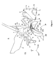
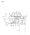
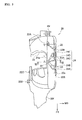
- Figs. 1 to 7 show a fender protector structure in accordance with embodiments of the present invention.
- Fig. 1 is an exploded perspective view of a port side of a vehicle body front portion including a fender protector structure.
- Fig. 2 is a bottom view of the fender protector structure.
- Fig. 3 is a top view of the fender protector.
- Fig. 4 is a perspective view of the fender protector when seen from the bottom.
- Fig. 5 is a perspective view of the fender protector when seen from an outer front side.
- Fig. 6 is a perspective view of the fender protector when seen from an outer rear side.
- Fig. 7 is a cross-sectional view taken along a line VII-VII in Fig. 3 . Further, in each drawing, "FR" indicates a vehicular front direction, "UP” indicates a vehicular upward direction and "WO" indicates an outer side in a vehicular width direction.
- a front pillar 3 may be assembled from a front end of a side sill 2 toward an upward direction.
- a dash panel 4 for dividing a front compartment FC and a vehicle compartment R may be bonded between the right and left front pillars 3 (only the left front pillar 3 is shown in Fig. 1 ).
- a hood ridge member 6 may protrude and be disposed in a front direction of the front pillar 3 via a hood ridge reinforcement 5.
- a dash side member 7 may be fastened at an upper side of the hood ridge reinforcement 5.
- a front side member 8 may extend along a vehicular front-and-rear direction at lower ends of both sides in a vehicular width direction of the front compartment FC.
- a sub-frame (not shown) may be disposed in a bracket 9 fastened at the front end of the front side member 8.
- An arm of a front suspension (not shown) may be disposed in the sub-frame.
- a strut tower 10 may be assembled at an outer side in a vehicular width direction of the front side member 8. An upper end of the strut tower 10 may be fastened at an inner side of the hood ridge reinforcement 5.
- the fender protector structure in accordance with embodiments of the present invention may be set in the vehicle body framework structure as described above. As shown in Fig. 1 , the fender protector structure may include the front fender panel 1, which may be disposed at a vehicle width outer side of the vehicle body framework structure, and a fender protector 20.
- the fender panel 1 forms a part of a vehicle body outer plate and may be disposed on the vehicle body framework structure at numerous points so as to cover an outer side in a vehicular width direction of a front wheel well 29.
- an upper end installing portion 1a of the fender panel 1 may be fastened at an upper surface 7a of the dash side member 7.
- a front end installing portion 1 b of the fender panel 1 may be fastened at a front end side surface 5a of the hood ridge reinforcement 5, while a lower end installing portion 1c of the fender panel 1 may be fastened at a lower end side surface 3a of the front pillar 3.
- a lower portion rear end installing portion 1d of the fender panel 1 may be fastened at a lower end rear surface 3b of the front pillar 3, while an upper portion rear end installing portion 1e of the fender panel 1 may be fastened at an intermediate portion rear surface 3c of the front pillar 3. Also, a rear portion upper side installing portion 1f of the fender panel 1 may be fastened at an intermediate portion side surface 3d of the front pillar 3.
- the arrows shown around a periphery of the fender panel 1 in Fig. 1 indicate the fastening directions of the bolts.
- a wheel arch portion 1 W may be formed at a lower end of the fender panel 1.
- the wheel arch portion 1W may be bent in an arc shape. From Fig. 1 , it may be understood that the fender panel may lack an installing point for fastening to the vehicle body framework structure at least at a peripheral intermediate portion 1Wm of the wheel arch portion 1 W.
- the fender protector 20 may be molded by synthetic resin in an approximately semi-arc panel shape that covers an outer periphery of a vehicle wheel well 29. Further, the fender protector 20 may prevent splash mud or rainwater from intruding into the vehicle body framework structure in the wheel well 29.
- a plurality of fixing portions 22, 22A, 22B, 22C, 20f and 20r for fixing the fender protector 20 to the vehicle body framework structure is disposed in the fender protector 20 along the vehicular front-and-rear direction.
- the fixing portions 22, 22A, 22B, 22C, 20f and 20r overlap a part of the vehicle body framework structure, such as a flange portion 5F in Fig. 7 , so as to be fixed to the vehicle body framework structure by clips C. While clips C are described, it should be understood that any other appropriate fastener, including, but not limited to, screws, rivets, welds, and bolts may be used without departing from the scope of the present invention.
- a cutout portion 21 for fitting the strut tower 10 may be formed at an upper side intermediate portion of the fender protector 20.
- the first fixing portion 22 may be disposed adjacent to a side edge portion 21 a of the cutout portion 21 at an approximately intermediate position in the vehicular width direction.
- the second fixing portion 22A may be disposed rearward from the first fixing portion 22 at a distance L.
- the fixing portions 20f and 20r may be disposed at the front and rear ends of the fender protector 20.
- a plurality of fixing portions 23, 23A and 23B may be formed at an end edge portion 20S in the vehicular width direction outer side of the fender protector 20.
- the fixing portions 23, 23A and 23B may be configured to be fixed to the fender panel 1 at or near the peripheral intermediate portion 1Wm of the wheel arch portion 1 W of the fender panel 1.
- the fixing portions 23, 23A and 23B may overlap with a part of the fender panel 1, such as a flange portion 1 F in Fig. 7 , such that the fixing portions 23, 23A and 23B are fixed to the fender panel 1 by clips C.
- the fixing portions 23, 23A and 23B may be formed in numerous regions along the vehicular front-and-rear direction and may be formed at predetermined intervals. Further, because the fixing portions 23, 23A and 23B may be formed to be recessed downwardly from an upper surface of an outer peripheral wall 20a of the fender protector 20, a step is formed between the fixing portions 23, 23A and 23B and the outer peripheral wall 20a.
- reinforcing beam portions 24 and 25 may be formed in the fender protector 20.
- the reinforcing beam portions 24 and 25 are shown formed extending from a fixing portion, such as first fixing portion 22 and second fixing portion 22A, at the vehicle body framework structure in the vehicular width direction inner side, to the peripheral intermediate portion 1Wm of the wheel arch portion 1W of the fender panel 1 at an end edge portion (end) 20S in the vehicular width direction outer side.
- the reinforcing beam portion 24 extending from the first fixing portion 22 toward the vehicular width direction outer side may include a plurality (five shown) of the reinforcing beam portions 24A-E radially extending from the first fixing portion 22. Further, the reinforcing beam portion 25 may extend from the second fixing portion 22A extends in the forward direction toward the fixing portion 23B, and the reinforcing beam portion 24E extending from the first fixing portion 22 extends rearward toward the fixing portion 23B.
- fixing portions 23, 23A and 23B formed at the end edge portion 20S in the vehicular width direction of the fender protector 20 may be disposed to be adjacent to two reinforcing beam portions (e.g., any two of 24A to 24E and 25). That is, as shown, fixing portion 23 may be disposed between the reinforcing beam portions 24A and 24B at the end edge portion 20S in the vehicular width direction of the fender protector 20, while the fixing portion 23A may be disposed between the reinforcing beam portions 24C and 24D at the end edge portion 20S in the vehicular width direction of the fender protector 20.
- the fixing portion 23B may be disposed between the reinforcing beam portions 24E and 25 at the end edge portion 20S in the vehicular width direction of the fender protector 20. While a fender protector 20 is illustrated having three fixing portions 23, 23A, and 23B, and six reinforcing beam portions 24A, 24B, 24C, 24D, 24E, and 25, it should be understood that fender protectors having fewer or additional fixing portions or reinforcing beam portions may be used without departing from the scope of the present invention.
- inclined surfaces 26 and 26A may be formed as a portion of the end edge portion 20S and may be disposed between two adjacent reinforcing beam portions (any two of 24A to 24E and 25) where the fixing portions 23, 23A and 23B are not disposed.
- the inclined surfaces 26 and 26A are shown inclined from the surface which define the fixing portions 23, 23A and 23B to the outer peripheral surface 20a.
- the reinforcing beam portions 24 and 25 may be formed with upwardly convex beams. That is, as shown in Fig. 4 , a back surface (a lower surface) of the fender protector 20 is formed with a plurality of grooves. Also, the grooves may protrude to form an upper surface, which may be "taller" than the outer peripheral surface 20a as shown in Figs. 5 and 6 .
- a hood ridge upper panel 5b may extended in a downward direction.
- the hood ridge upper panel 5b may form an inner side of the hood ridge reinforcement 5, which may become a closed cross section.
- a lower end of an extending portion 5c which may extend form the hood ridge upper panel 5b, may be bent in a cross-sectional L-shape at the vehicular width direction outer side to form a flange portion 5F.
- the flange portion 5F may overlap the fixing portion 22 and may then be fixed by clip C.
- a lower portion of the hood ridge upper panel 5b may be bonded to a suspension spring support 10a.
- the suspension spring support 10a may form an upper end surface of the strut tower 10.
- a peripheral portion 1 Wm of the wheel arch portion 1 W of the fender panel 1 may be bent toward the vehicle inner side to form a flange portion 1 F.
- the flange portion 1 F may overlap the fixing portions 23, 23A and 23B in the fender protector 20 and may then be fixed by clips C.
- Fig. 7 illustrates the fixing portion 22, the reinforcing beam 24C and the fixing portion 23A.
- the reinforcing beams 24A, 24B, 24D, and 24E and the fixing portions 23 and 23B may have similar cross-sectional shapes.
- a longitudinal wall portion 27 may be formed at the outer end in the vehicular width direction of the reinforcing beam portions 24 and 25.
- a foaming resin 28 may be disposed in a gap between the longitudinal wall portion 27 and the fender panel 1 to act as a buffering body for absorbing additional force.
- Foaming resin 28 may be pre-formed to fit into gap between longitudinal wall portion 27 and fender panel 1 or may, in the alternative, be "spray" molded as an injectable and expandable foam in place following assembly of fender protector 20 to fender panel 1.
- fender protector structure as described above, as shown in Fig. 7 , if an outer force F is exerted upon fender panel 1 from the lateral outer side to the vehicular width direction inner side, fender panel 1 may bend toward the vehicular width direction inner side from outer force F.
- the reinforcing beam portions 24 and 25 may be formed in the fender protector 20.
- the reinforcing beam portions 24 and 25 may be formed to extend from the fixing portions 22 and 22A which may be fixed to the vehicle body framework structure in the vehicular width direction inner side to the outer end in the vehicular width direction, which may be fixed to the peripheral intermediate portion 1 Wm of the wheel arch portion 1 W of the fender panel 1.
- the outer force F i.e., the load
- the rigidity of the fender protector structure with respect to the outer force F may increase, it is possible to reduce the bending of the peripheral intermediate portion 1 Wm of the wheel arch portion 1 W of the fender panel 1.
- a plurality of the reinforcing beams 24A to 24E may be formed.
- the reinforcing beams 24A to 24E may extend radially from the fixing portion 22 toward the vehicular width direction outer side.
- the ends at the vehicular width direction outer side of the reinforcing beam portions 24A to 24E may be disposed throughout a relatively broader range of the peripheral intermediate portion 1Wm.
- the rigidity of the fender protector 20 may be increased by the reinforcing beam portion 24, it may be possible to expand a region where the bending of the wheel arch portion 1 W is suppressed.
- a plurality of the reinforcing beams may be disposed so as to have the fixing portions 23, 23A and 23B disposed therebetween.
- the fixing portions 23, 23A and 23B may be disposed between the reinforcing beams (any two of 24A to 24E and 25), which have a high rigidity, it is possible to increase the rigidity of the fender protector 20 and the fender panel 1 during installation by increasing the rigidity of the fixing portions 23, 23A and 23B.
- a plurality of the reinforcing beam portions 24 and 25 may be formed.
- the reinforcing beam portions 24 and 25 may extend from a plurality of the fixing portions 22 and 22A spaced in the vehicular width direction inner side along the vehicular front-and-rear direction toward the fixing portion 23B which may be fixed to the peripheral intermediate portion 1Wm of the wheel arch portion 1 W. That is, a plurality of the reinforcing beam portions may be formed.
- the inclined surfaces 26 and 26A of the end edge portion 20S at the vehicular width direction outer side of the fender protector 20 may be formed between the ends in the vehicular width direction outer side of a plurality of the reinforcing beams (any two of 24A to 24E and 25). That is, because the bent shape may be formed with the inclined surfaces 26 and 26A, it is possible to increase the rigidity of the end edge portion 20S.
- the foaming resin 28 to act as the buffering body may be disposed between the fender panel 1 and the longitudinal wall portion 27 as the outer end in the vehicular width direction of the reinforcing beam portions 24 and 25. As such, an outer force F may be absorbed by the foaming resin 28. Also, in embodiments wherein the fender protector 20 only directly contacts the fender panel 1, friction between the fender protector 20 and fender panel 1 may produce a vibration or sound. However, where the foaming resin 28 is inserted and supported as described above, such a problem may be suppressed.
- the buffering body may include other materials having a buffering function such as, for example, a foaming urethane, unwoven fabric, etc.
- the reinforcing beam portions 24 and 25 may be formed as upwardly convex beams. As such, it is possible to form the reinforcing beam portions 24 and 25 into the fender protector relatively easily. Further, it is possible to execute an operation to fasten the fender panel 1 and the fender protector 20 together by inserting a finger from a downward direction into grooves defined by the reinforcing beam portions 24 and 25. In particular, it may be seen from a downward direction that a groove may be formed between two reinforcing beam portions (any two of 24A to 24E and 25) which may define the fixing portions 23 and 23A.
- the fender protector 20 by inserting, for example, a thumb and an index finger into the two reinforcing beam portions (e.g., any two of 24A to 24E and 25), it may also be possible to more smoothly and securely execute an operation to attach the fixing portions 23, 23A and 23B to the fender panel 1 with clips C.
- a thumb and an index finger into the two reinforcing beam portions (e.g., any two of 24A to 24E and 25)
Landscapes
- Engineering & Computer Science (AREA)
- Mechanical Engineering (AREA)
- Chemical & Material Sciences (AREA)
- Combustion & Propulsion (AREA)
- Transportation (AREA)
- Architecture (AREA)
- Structural Engineering (AREA)
- Body Structure For Vehicles (AREA)
Abstract
Description
- The present invention relates to a fender protector structure of a vehicle and particularly, but not exclusively, to a fender protector structure having a reinforcing beam portion extending between a body panel and a fender panel. Aspects of the invention relate to a structure, to a method and to a vehicle.
- Japanese Laid-Open Patent Publication No.
(Hei) 11-208514 - In such a structure, although fixing points can be formed on the fender protector for attachment to the fender panel at a vehicle body side at each end of a periphery of the wheel arch portion, it is difficult to establish a fixing point at the vehicle side at a peripheral intermediate portion of the wheel arch portion. Accordingly, sufficient rigidity may be lacking at the peripheral intermediate portion of the wheel arch portion for accommodating a load applied from the lateral outer side.
- Thus, according to Patent Document 1, a rib is disposed at an outer end of the fender protector with respect to a vehicular width direction of the fender protector. Further, the rib contacts an inner surface of the fender panel to thereby enhance and improve the rigidity at the peripheral intermediate portion of the wheel arch portion.
- However, since the rib extends only a short distance from the outer end of the fender protector in the vehicular width direction in the structure disclosed in Patent Document 1, the structure still lacks sufficient rigidity (e.g., at the lateral inner portion in the vehicular width direction compared to the rib). As a result, the structure lacks sufficient rigidity to accommodate an outer force exerted from the lateral outer side to the peripheral intermediate portion of the wheel arch portion.
- It is an aim of the present invention to address this issue and to improve upon known technology. Embodiments of the invention may provide a fender protector structure wherein a reinforcing portion with a bead is formed along a vehicular width direction of a fender protector, increasing the rigidity against an outer force exerted from a vehicular width direction with respect to a peripheral intermediate portion of a wheel arch portion of a fender panel. Other aims and advantages of the invention will become apparent from the following description, claims and drawings.
- Aspects of the invention therefore provide a structure, a method and a vehicle as claimed in the appended claims.
- According to another aspect of the invention for which protection is sought, there is provided a fender protector structure of a vehicle, comprising a body structure including a body panel and a fender panel, the body structure defining a wheel well, a fender protector connected to the body structure and covering an outer periphery of the wheel well and a reinforcing beam portion of the fender protector extending from the body panel to the fender panel.
- In an embodiment, the reinforcing beam portion comprises a first fixing portion configured to be fixed to the body panel.
- In an embodiment, the reinforcing beam portion comprises a plurality of reinforcing beams extending radially from the first fixing portion toward the fender panel.
- In an embodiment, the reinforcing beam portion comprises an inclined surface disposed between two adjacent reinforcing beams.
- In an embodiment, the inclined surface extends from an end edge of the fender protector towards the first fixing portion.
- In an embodiment, the reinforcing beam portion comprises a plurality of reinforcing beams and a second fixing portion fixed to the fender panel. The second fixing portion may be disposed between the plurality of the reinforcing beams.
- In an embodiment, the first fixing portion comprises a plurality of fixing points. The reinforcing beam portion may comprise a plurality of reinforcing beams extending from the first fixing portion toward the fender panel.
- The structure may comprise a buffering body disposed between the reinforcing beam portion and the fender panel.
- In an embodiment, the reinforcing beam portion includes at least one reinforcing beam formed with an upwardly convex beam shape.
- In an embodiment, the reinforcing beam portion is formed integrally with the fender protector.
- In an embodiment, the reinforcing beam portion is disposed on the fender protector at a location corresponding to an upper portion of the wheel well.
- In an embodiment, the fender protector comprises a panel shape corresponding to a shape of the wheel well.
- According to a further aspect of the invention for which protection is sought, there is provided a method to manufacture a body of a vehicle, the method comprising defining a wheel well with a body panel and a fender panel of a body structure, covering an outer periphery of the wheel well with a fender protector, extending a reinforcing beam portion of the fender protector from the body panel to the fender panel and fixing the reinforcing beam portion of the fender protector to the body panel with a fixing portion.
- The method may comprise providing an inclined surface between two adjacent reinforcing beams of the reinforcing beam portion.
- The method may comprise extending the inclined surface from an edge of the fender protector toward the fixing portion.
- The method may comprise installing a buffering body between the reinforcing beam portion and the fender panel.
- According to a still further aspect of the invention for which protection is sought, there is provided a fender protector structure of a vehicle, comprising a body structure including a body panel and a fender panel, the body structure defining a wheel well, a fender protector means connected to the body structure for covering an outer periphery of the wheel well and a means for reinforcing the fender protector extending from the body panel to the fender panel, wherein the means for reinforcing comprises a means for fixing the fender protector to the body panel.
- In an embodiment, the means for reinforcing comprises a plurality of reinforcing beams extending radially from the means for fixing toward the fender panel.
- The structure may comprise an inclined surface disposed between two adjacent reinforcing beams.
- The structure may comprise a means for buffering disposed between the means for reinforcing and the fender panel.
- For example, a fender protector structure of a vehicle may comprise a body structure including a body panel and a fender panel, the body structure defining a wheel well, a fender protector connected to the body structure and covering an outer periphery of the wheel well, and a reinforcing beam portion of the fender protector extending from the body panel to the fender panel.
- In another example, a method to manufacture a body of a vehicle comprises defining a wheel well with a body panel and a fender panel of a body structure, covering an outer periphery of the wheel well with a fender protector, extending a reinforcing beam portion of the fender protector from the body panel to the fender panel, and fixing the reinforcing beam portion of the fender protector to the body panel with a fixing portion.
- A fender protector structure of a vehicle may comprise a body structure including a body panel and a fender panel, the body structure defining a wheel well, a fender protector means connected to the body structure for covering an outer periphery of the wheel well, and a means for reinforcing the fender protector extending from the body panel to the fender panel, wherein the means for reinforcing includes a means for fixing the fender protector to the body panel.
- In embodiments of the invention a fender protector is formed by using molded resin and may have a concave shape when seen from an upper direction and a concave (groove) shape when seen from a downward direction. Thus, a bead shape can be seen regardless of whether it is viewed from the upper or downward direction.
- Within the scope of this application, it is envisaged that the various aspects, embodiments, examples, features and alternatives set out in the preceding paragraphs, in the claims and/or in the following description and drawings may be taken individually or in any combination thereof.
- The present invention will now be described, by way of example only, with reference to the accompanying drawings, in which:
-
Fig. 1 is an exploded perspective view of a vehicle body structure including a fender protector in accordance with embodiments of the present invention; -
Fig. 2 is a bottom view of a fender protector in accordance with embodiments of the present invention; -
Fig. 3 is a top view of the fender protector in accordance with embodiments of the present invention; -
Fig. 4 is a perspective view of the fender protector in accordance with embodiments of the present invention when viewed from the bottom; -
Fig. 5 is a perspective view of the fender protector in accordance with embodiments of the present invention when viewed from an outer front side; -
Fig. 6 is a perspective view of the fender protector in accordance with embodiments of the present invention when viewed from an outer rear side; and -
Fig. 7 is a cross-sectional view of the fender protector structure taken along a line VII-VII inFig. 3 . -
Figs. 1 to 7 show a fender protector structure in accordance with embodiments of the present invention.Fig. 1 is an exploded perspective view of a port side of a vehicle body front portion including a fender protector structure.Fig. 2 is a bottom view of the fender protector structure.Fig. 3 is a top view of the fender protector.Fig. 4 is a perspective view of the fender protector when seen from the bottom.Fig. 5 is a perspective view of the fender protector when seen from an outer front side.Fig. 6 is a perspective view of the fender protector when seen from an outer rear side.Fig. 7 is a cross-sectional view taken along a line VII-VII inFig. 3 . Further, in each drawing, "FR" indicates a vehicular front direction, "UP" indicates a vehicular upward direction and "WO" indicates an outer side in a vehicular width direction. - As shown in
Fig. 1 , in a vehicle body framework structure of select embodiments, afront pillar 3 may be assembled from a front end of a side sill 2 toward an upward direction. Further, adash panel 4 for dividing a front compartment FC and a vehicle compartment R may be bonded between the right and left front pillars 3 (only theleft front pillar 3 is shown inFig. 1 ). Also, a hood ridge member 6 may protrude and be disposed in a front direction of thefront pillar 3 via a hood ridge reinforcement 5. Additionally, a dash side member 7 may be fastened at an upper side of the hood ridge reinforcement 5. - Further, a front side member 8 may extend along a vehicular front-and-rear direction at lower ends of both sides in a vehicular width direction of the front compartment FC. A sub-frame (not shown) may be disposed in a
bracket 9 fastened at the front end of the front side member 8. An arm of a front suspension (not shown) may be disposed in the sub-frame. - Also, a
strut tower 10 may be assembled at an outer side in a vehicular width direction of the front side member 8. An upper end of thestrut tower 10 may be fastened at an inner side of the hood ridge reinforcement 5. - The fender protector structure in accordance with embodiments of the present invention may be set in the vehicle body framework structure as described above. As shown in
Fig. 1 , the fender protector structure may include the front fender panel 1, which may be disposed at a vehicle width outer side of the vehicle body framework structure, and afender protector 20. - The fender panel 1 forms a part of a vehicle body outer plate and may be disposed on the vehicle body framework structure at numerous points so as to cover an outer side in a vehicular width direction of a
front wheel well 29. In select embodiments, by using bolts (not shown), an upper end installing portion 1a of the fender panel 1 may be fastened at an upper surface 7a of the dash side member 7. Further, a frontend installing portion 1 b of the fender panel 1 may be fastened at a front end side surface 5a of the hood ridge reinforcement 5, while a lower end installing portion 1c of the fender panel 1 may be fastened at a lowerend side surface 3a of thefront pillar 3. A lower portion rearend installing portion 1d of the fender panel 1 may be fastened at a lower endrear surface 3b of thefront pillar 3, while an upper portion rearend installing portion 1e of the fender panel 1 may be fastened at an intermediate portionrear surface 3c of thefront pillar 3. Also, a rear portion upper side installing portion 1f of the fender panel 1 may be fastened at an intermediateportion side surface 3d of thefront pillar 3. The arrows shown around a periphery of the fender panel 1 inFig. 1 indicate the fastening directions of the bolts. - A wheel
arch portion 1 W may be formed at a lower end of the fender panel 1. The wheelarch portion 1W may be bent in an arc shape. FromFig. 1 , it may be understood that the fender panel may lack an installing point for fastening to the vehicle body framework structure at least at a peripheral intermediate portion 1Wm of the wheelarch portion 1 W. - The
fender protector 20 may be molded by synthetic resin in an approximately semi-arc panel shape that covers an outer periphery of a vehicle wheel well 29. Further, thefender protector 20 may prevent splash mud or rainwater from intruding into the vehicle body framework structure in thewheel well 29. - A plurality of fixing
portions fender protector 20 to the vehicle body framework structure is disposed in thefender protector 20 along the vehicular front-and-rear direction. As shown inFig. 7 , the fixingportions flange portion 5F inFig. 7 , so as to be fixed to the vehicle body framework structure by clips C. While clips C are described, it should be understood that any other appropriate fastener, including, but not limited to, screws, rivets, welds, and bolts may be used without departing from the scope of the present invention. - A
cutout portion 21 for fitting thestrut tower 10 may be formed at an upper side intermediate portion of thefender protector 20. Further, the first fixingportion 22 may be disposed adjacent to aside edge portion 21 a of thecutout portion 21 at an approximately intermediate position in the vehicular width direction. Also, thesecond fixing portion 22A may be disposed rearward from the first fixingportion 22 at a distance L. Moreover, the fixingportions fender protector 20. - Further, a plurality of fixing
portions end edge portion 20S in the vehicular width direction outer side of thefender protector 20. The fixingportions arch portion 1 W of the fender panel 1. As shown inFig. 7 , the fixingportions flange portion 1 F inFig. 7 , such that the fixingportions The fixing portions portions peripheral wall 20a of thefender protector 20, a step is formed between the fixingportions peripheral wall 20a. - Also, in the present embodiment, reinforcing
beam portions fender protector 20. The reinforcingbeam portions portion 22 and second fixingportion 22A, at the vehicle body framework structure in the vehicular width direction inner side, to the peripheral intermediate portion 1Wm of the wheelarch portion 1W of the fender panel 1 at an end edge portion (end) 20S in the vehicular width direction outer side. - The reinforcing
beam portion 24 extending from the first fixingportion 22 toward the vehicular width direction outer side may include a plurality (five shown) of the reinforcingbeam portions 24A-E radially extending from the first fixingportion 22. Further, the reinforcingbeam portion 25 may extend from thesecond fixing portion 22A extends in the forward direction toward the fixingportion 23B, and the reinforcingbeam portion 24E extending from the first fixingportion 22 extends rearward toward the fixingportion 23B. - Further, the fixing
portions end edge portion 20S in the vehicular width direction of thefender protector 20 may be disposed to be adjacent to two reinforcing beam portions (e.g., any two of 24A to 24E and 25). That is, as shown, fixingportion 23 may be disposed between the reinforcingbeam portions end edge portion 20S in the vehicular width direction of thefender protector 20, while the fixingportion 23A may be disposed between the reinforcingbeam portions end edge portion 20S in the vehicular width direction of thefender protector 20. Also, the fixingportion 23B may be disposed between the reinforcingbeam portions end edge portion 20S in the vehicular width direction of thefender protector 20. While afender protector 20 is illustrated having three fixingportions beam portions - Also, as shown in
Figs. 5 and6 , inclined surfaces 26 and 26A may be formed as a portion of theend edge portion 20S and may be disposed between two adjacent reinforcing beam portions (any two of 24A to 24E and 25) where the fixingportions portions peripheral surface 20a. - Further, the reinforcing
beam portions Fig. 4 , a back surface (a lower surface) of thefender protector 20 is formed with a plurality of grooves. Also, the grooves may protrude to form an upper surface, which may be "taller" than the outerperipheral surface 20a as shown inFigs. 5 and6 . - A cross-section of the
fender protector 20 and vehicle body framework structure will be explained with reference toFig. 7 . In select embodiments, a hood ridgeupper panel 5b may extended in a downward direction. The hood ridgeupper panel 5b may form an inner side of the hood ridge reinforcement 5, which may become a closed cross section. Further, a lower end of an extendingportion 5c, which may extend form the hood ridgeupper panel 5b, may be bent in a cross-sectional L-shape at the vehicular width direction outer side to form aflange portion 5F. Theflange portion 5F may overlap the fixingportion 22 and may then be fixed by clip C. Moreover, a lower portion of the hood ridgeupper panel 5b may be bonded to asuspension spring support 10a. Thesuspension spring support 10a may form an upper end surface of thestrut tower 10. - A peripheral portion 1 Wm of the wheel
arch portion 1 W of the fender panel 1 may be bent toward the vehicle inner side to form a flange portion 1 F. Theflange portion 1 F may overlap the fixingportions fender protector 20 and may then be fixed by clips C. Further,Fig. 7 illustrates the fixingportion 22, the reinforcingbeam 24C and the fixingportion 23A. However, the reinforcingbeams portions - As shown in
Fig. 7 , in the present embodiment, alongitudinal wall portion 27 may be formed at the outer end in the vehicular width direction of the reinforcingbeam portions resin 28 may be disposed in a gap between thelongitudinal wall portion 27 and the fender panel 1 to act as a buffering body for absorbing additional force. Foamingresin 28 may be pre-formed to fit into gap betweenlongitudinal wall portion 27 and fender panel 1 or may, in the alternative, be "spray" molded as an injectable and expandable foam in place following assembly offender protector 20 to fender panel 1. - According to the fender protector structure as described above, as shown in
Fig. 7 , if an outer force F is exerted upon fender panel 1 from the lateral outer side to the vehicular width direction inner side, fender panel 1 may bend toward the vehicular width direction inner side from outer force F. - In certain embodiments, the reinforcing
beam portions fender protector 20. The reinforcingbeam portions portions arch portion 1 W of the fender panel 1. As such, it may be possible to transfer the outer force F (i.e., the load) from the fender panel 1 to the vehicle body framework structure via the reinforcingbeam portions arch portion 1 W of the fender panel 1. - Further, in certain embodiments, a plurality of the reinforcing
beams 24A to 24E may be formed. The reinforcingbeams 24A to 24E may extend radially from the fixingportion 22 toward the vehicular width direction outer side. As such, the ends at the vehicular width direction outer side of the reinforcingbeam portions 24A to 24E may be disposed throughout a relatively broader range of the peripheral intermediate portion 1Wm. Also, because the rigidity of thefender protector 20 may be increased by the reinforcingbeam portion 24, it may be possible to expand a region where the bending of the wheelarch portion 1 W is suppressed. - Also, in certain embodiments, a plurality of the reinforcing beams (any two of 24A to 24E and 25) may be disposed so as to have the fixing
portions portions fender protector 20 and the fender panel 1 during installation by increasing the rigidity of the fixingportions - Further, in certain embodiments, a plurality of the reinforcing
beam portions beam portions portions portion 23B which may be fixed to the peripheral intermediate portion 1Wm of the wheel arch portion 1 W. That is, a plurality of the reinforcing beam portions may be formed. As such, since it is possible to disperse the outer force F into the plurality of the fixingportions beam portions fender protector 20. - Also, in certain embodiments, the
inclined surfaces end edge portion 20S at the vehicular width direction outer side of thefender protector 20 may be formed between the ends in the vehicular width direction outer side of a plurality of the reinforcing beams (any two of 24A to 24E and 25). That is, because the bent shape may be formed with theinclined surfaces end edge portion 20S. - Further, in certain embodiments, the foaming
resin 28 to act as the buffering body may be disposed between the fender panel 1 and thelongitudinal wall portion 27 as the outer end in the vehicular width direction of the reinforcingbeam portions resin 28. Also, in embodiments wherein thefender protector 20 only directly contacts the fender panel 1, friction between thefender protector 20 and fender panel 1 may produce a vibration or sound. However, where the foamingresin 28 is inserted and supported as described above, such a problem may be suppressed. Moreover, the buffering body may include other materials having a buffering function such as, for example, a foaming urethane, unwoven fabric, etc. - Also, the reinforcing
beam portions beam portions fender protector 20 together by inserting a finger from a downward direction into grooves defined by the reinforcingbeam portions portions fender protector 20 by inserting, for example, a thumb and an index finger into the two reinforcing beam portions (e.g., any two of 24A to 24E and 25), it may also be possible to more smoothly and securely execute an operation to attach the fixingportions - While the present invention has been presented with respect to a limited number of embodiments, those skilled in the art, having benefit of this disclosure, will appreciate that other embodiments may be devised which do not depart from the scope of the present invention. Accordingly, the scope of the invention should be limited only by the attached claims.
- The present application claims priority from Japanese Patent Application No.
2007-324479, filed 17th December 2007
Claims (15)
- A structure for a vehicle, comprising:a body structure including a body panel and a fender panel, the body structure defining a wheel well;a fender protector connected to the body structure and covering an outer periphery of the wheel well; anda reinforcing beam portion of the fender protector extending from the body panel to the fender panel.
- A structure as claimed in claim 1, wherein the reinforcing beam portion comprises a first fixing portion configured to be fixed to the body panel.
- A structure as claimed in claim 2, wherein the reinforcing beam portion comprises a plurality of reinforcing beams extending radially from the first fixing portion toward the fender panel.
- A structure as claimed in claim 3, wherein the reinforcing beam portion comprises an inclined surface disposed between two adjacent reinforcing beams.
- A structure as claimed in claim 4, wherein the inclined surface extends from an end edge of the fender protector towards the first fixing portion.
- A structure as claimed in any of claims 2 to 5, wherein:the reinforcing beam portion comprises a plurality of reinforcing beams and a second fixing portion fixed to the fender panel; andthe second fixing portion is disposed between the plurality of the reinforcing beams.
- A structure as claimed in any of claims 2 to 6, wherein:the first fixing portion comprises a plurality of fixing points; andthe reinforcing beam portion comprises a plurality of reinforcing beams extending from the first fixing portion toward the fender panel.
- A structure as claimed in any preceding claim, comprising a buffering body disposed between the reinforcing beam portion and the fender panel.
- A structure as claimed in any preceding claim, wherein the reinforcing beam portion comprises at least one reinforcing beam formed with an upwardly convex beam shape.
- A structure as claimed in any preceding claim, wherein the reinforcing beam portion is formed integrally with the fender protector.
- A structure as claimed in any preceding claim, wherein the reinforcing beam portion is disposed on the fender protector at a location corresponding to an upper portion of the wheel well.
- A structure as claimed in any preceding claim, wherein the fender protector comprises a panel shape corresponding to a shape of the wheel well.
- A method of manufacturing a body of a vehicle, the method comprising:defining a wheel well with a body panel and a fender panel of a body structure;covering an outer periphery of the wheel well with a fender protector;extending a reinforcing beam portion of the fender protector from the body panel to the fender panel; and
fixing the reinforcing beam portion of the fender protector to the body panel with a fixing portion. - A method as claimed in claim 13, comprising:providing an inclined surface between two adjacent reinforcing beams of the reinforcing beam portion;extending the inclined surface from an edge of the fender protector toward the fixing portion; and/or
installing a buffering body between the reinforcing beam portion and the fender panel. - A vehicle having a structure as claimed in any of claims 1 to 12.
Applications Claiming Priority (1)
| Application Number | Priority Date | Filing Date | Title |
|---|---|---|---|
| JP2007324479A JP4450064B2 (en) | 2007-12-17 | 2007-12-17 | Fender protector structure |
Publications (2)
| Publication Number | Publication Date |
|---|---|
| EP2072379A1 true EP2072379A1 (en) | 2009-06-24 |
| EP2072379B1 EP2072379B1 (en) | 2011-06-08 |
Family
ID=40340514
Family Applications (1)
| Application Number | Title | Priority Date | Filing Date |
|---|---|---|---|
| EP08171724A Active EP2072379B1 (en) | 2007-12-17 | 2008-12-16 | Fender Protector Structure |
Country Status (5)
| Country | Link |
|---|---|
| US (1) | US7909392B2 (en) |
| EP (1) | EP2072379B1 (en) |
| JP (1) | JP4450064B2 (en) |
| KR (1) | KR101001797B1 (en) |
| CN (1) | CN101462555B (en) |
Cited By (1)
| Publication number | Priority date | Publication date | Assignee | Title |
|---|---|---|---|---|
| FR2950854A1 (en) * | 2009-10-05 | 2011-04-08 | Peugeot Citroen Automobiles Sa | Motor vehicle's front part, has closing part extended above body of window post at level of lower front part, and extension of closing part provided with fixing unit for fixing fender and interface part of vehicle |
Families Citing this family (24)
| Publication number | Priority date | Publication date | Assignee | Title |
|---|---|---|---|---|
| US8087721B2 (en) * | 2009-08-17 | 2012-01-03 | Honda Motor Co., Ltd. | Reinforcement bracket and related methods for on-line painting |
| JP4996665B2 (en) * | 2009-10-19 | 2012-08-08 | 本田技研工業株式会社 | Body structure of pillar garnish and fender panel |
| JP5741209B2 (en) * | 2011-05-20 | 2015-07-01 | スズキ株式会社 | Splash cover mounting structure |
| JP5312535B2 (en) * | 2011-07-30 | 2013-10-09 | 本田技研工業株式会社 | Auto body structure |
| CN102530099A (en) * | 2011-12-31 | 2012-07-04 | 重庆长安汽车股份有限公司 | Welded structure of rear wheel hub assembly, rear floor and rear longitudinal beam of automobile |
| KR101361372B1 (en) * | 2012-06-18 | 2014-02-10 | 기아자동차주식회사 | Device for assembling fender panel of vehicle |
| CA2882393C (en) * | 2012-08-21 | 2016-06-28 | Nippon Steel & Sumitomo Metal Corporation | Crash box and automobile chassis |
| US9428121B2 (en) * | 2012-11-29 | 2016-08-30 | Techstyles, Inc. | Acoustic wheel well liner |
| DE102014107609B3 (en) * | 2014-05-28 | 2015-10-29 | Wegu Gmbh Leichtbausysteme | Plastic mudguard with directly molded, against a main area of the fender deflectable strainer |
| US11097782B2 (en) | 2014-11-24 | 2021-08-24 | Tesseract Structural Innovations, Inc. | Sill beam uniform deceleration unit |
| EP3224035B1 (en) * | 2014-11-24 | 2021-03-31 | Tesseract Structural Innovations Inc. | Uniform deceleration unit |
| US11021120B2 (en) | 2014-11-24 | 2021-06-01 | Tesseract Structural Innovations, Inc. | Uniform deceleration unit |
| US9394005B1 (en) * | 2015-02-12 | 2016-07-19 | Autoliv Asp, Inc. | Foot well intrusion deflection systems and related methods and apparatus |
| WO2016194233A1 (en) * | 2015-06-05 | 2016-12-08 | 本田技研工業株式会社 | Vehicle body structure |
| JP2019514779A (en) | 2016-04-21 | 2019-06-06 | テッサラクト ストラクチュラル イノベーションズ,インコーポレイテッド | Constant deceleration unit crash box |
| US9718501B1 (en) * | 2016-06-23 | 2017-08-01 | Harry Blake Manley | Fender integrated aerodynamic mud, rock and splash guard |
| JP6477762B2 (en) * | 2017-03-28 | 2019-03-06 | マツダ株式会社 | Front body structure of the vehicle |
| CN110997466B (en) * | 2017-08-07 | 2022-04-15 | 标致雪铁龙汽车股份有限公司 | Vehicle front body side structure |
| TWM562255U (en) * | 2018-03-21 | 2018-06-21 | Shi Fu Man | Vehicle fender structure easy for storage and delivery |
| JP2021522097A (en) * | 2018-04-16 | 2021-08-30 | テッサラクト ストラクチュラル イノベーションズ,インコーポレイテッド | Uniform deceleration unit |
| US10882564B2 (en) * | 2019-02-27 | 2021-01-05 | Nissan North America, Inc. | Wheel housing liner assembly |
| US11685447B2 (en) * | 2019-04-26 | 2023-06-27 | Bombardier Recreational Products Inc. | Guard assembly and vehicle having same |
| US11648892B2 (en) * | 2020-06-01 | 2023-05-16 | Inoac Corporation | Noise reflector, fender liner, and silencing method |
| JP2025070311A (en) * | 2023-10-19 | 2025-05-02 | トヨタ自動車株式会社 | Fender liner and vehicle front structure |
Citations (3)
| Publication number | Priority date | Publication date | Assignee | Title |
|---|---|---|---|---|
| JPH11208514A (en) | 1998-01-21 | 1999-08-03 | Suzuki Motor Corp | Mounting structure of fender lining |
| JP2007223397A (en) * | 2006-02-22 | 2007-09-06 | Nippon Plast Co Ltd | Protector panel for vehicle |
| JP2007324479A (en) | 2006-06-02 | 2007-12-13 | Toshiba Corp | Simulation model creation method, program, and semiconductor device manufacturing method |
Family Cites Families (15)
| Publication number | Priority date | Publication date | Assignee | Title |
|---|---|---|---|---|
| JPS6056680A (en) * | 1983-09-09 | 1985-04-02 | Nissan Motor Co Ltd | Fender protector |
| JPS60259574A (en) * | 1984-06-01 | 1985-12-21 | Daihatsu Motor Co Ltd | Rust prevention for joint part between steel plate and installation part for automobile |
| DE3539146A1 (en) * | 1985-11-05 | 1987-05-14 | Ford Werke Ag | WHEEL HOUSING LINING FOR MOTOR VEHICLES |
| JPS6297888U (en) * | 1985-12-12 | 1987-06-22 | ||
| JPH044950Y2 (en) * | 1986-09-08 | 1992-02-13 | ||
| JP2755518B2 (en) * | 1992-02-25 | 1998-05-20 | 本田技研工業株式会社 | Inna Fender |
| US5613710A (en) * | 1995-06-12 | 1997-03-25 | Waner; Alan R. | Dual rear wheel fender liner |
| US5829786A (en) * | 1996-06-25 | 1998-11-03 | Dahl; Roger S. | Fiberglass fender with yieldable mounting means |
| JP3543711B2 (en) * | 1999-12-24 | 2004-07-21 | トヨタ車体株式会社 | Car fender liner |
| JP2001260944A (en) * | 2000-03-17 | 2001-09-26 | Nippon Plast Co Ltd | Fender protector structure for vehicle |
| IT1320370B1 (en) * | 2000-05-26 | 2003-11-26 | San Valeriano S P A | THERMOFORMED PANEL AND PROCEDURE FOR ITS PRODUCTION. |
| KR20060073950A (en) * | 2003-09-05 | 2006-06-29 | 제너럴 일렉트릭 캄파니 | Vehicle fender |
| US7497509B2 (en) * | 2005-03-08 | 2009-03-03 | Toyoda Gosei Co., Ltd. | Exterior component |
| JP2008037335A (en) * | 2006-08-09 | 2008-02-21 | Kojima Press Co Ltd | Shock absorption mechanism of fender liner |
| JP4950621B2 (en) * | 2006-11-06 | 2012-06-13 | 林テレンプ株式会社 | Automotive splash shield |
-
2007
- 2007-12-17 JP JP2007324479A patent/JP4450064B2/en active Active
-
2008
- 2008-11-19 KR KR1020080114931A patent/KR101001797B1/en active Active
- 2008-12-08 US US12/329,805 patent/US7909392B2/en active Active
- 2008-12-09 CN CN200810182835.8A patent/CN101462555B/en active Active
- 2008-12-16 EP EP08171724A patent/EP2072379B1/en active Active
Patent Citations (3)
| Publication number | Priority date | Publication date | Assignee | Title |
|---|---|---|---|---|
| JPH11208514A (en) | 1998-01-21 | 1999-08-03 | Suzuki Motor Corp | Mounting structure of fender lining |
| JP2007223397A (en) * | 2006-02-22 | 2007-09-06 | Nippon Plast Co Ltd | Protector panel for vehicle |
| JP2007324479A (en) | 2006-06-02 | 2007-12-13 | Toshiba Corp | Simulation model creation method, program, and semiconductor device manufacturing method |
Cited By (1)
| Publication number | Priority date | Publication date | Assignee | Title |
|---|---|---|---|---|
| FR2950854A1 (en) * | 2009-10-05 | 2011-04-08 | Peugeot Citroen Automobiles Sa | Motor vehicle's front part, has closing part extended above body of window post at level of lower front part, and extension of closing part provided with fixing unit for fixing fender and interface part of vehicle |
Also Published As
| Publication number | Publication date |
|---|---|
| US7909392B2 (en) | 2011-03-22 |
| JP4450064B2 (en) | 2010-04-14 |
| CN101462555B (en) | 2011-03-23 |
| EP2072379B1 (en) | 2011-06-08 |
| CN101462555A (en) | 2009-06-24 |
| KR101001797B1 (en) | 2010-12-15 |
| US20090152901A1 (en) | 2009-06-18 |
| JP2009143469A (en) | 2009-07-02 |
| KR20090065435A (en) | 2009-06-22 |
Similar Documents
| Publication | Publication Date | Title |
|---|---|---|
| EP2072379B1 (en) | Fender Protector Structure | |
| JP5879938B2 (en) | Reinforcement structure for side panels at the rear of the vehicle | |
| JP6350482B2 (en) | Car deflector structure | |
| EP1808362A2 (en) | vehicle body | |
| JP2016107653A (en) | Back door structure for vehicle | |
| CN105683029A (en) | Suspension tower plate and suspension tower | |
| JP2020104569A (en) | Cowl top structure | |
| WO2008062763A1 (en) | Reinforcing structure of vehicle body | |
| CN113260531B (en) | Trunk lid of vehicle | |
| JP6106006B2 (en) | Front body structure of automobile | |
| JP5754339B2 (en) | Strut suspension mounting structure | |
| JP5951474B2 (en) | Rigid support structure | |
| JP5515956B2 (en) | Upper body structure of the vehicle | |
| JP4807249B2 (en) | Deck garnish | |
| JP7533210B2 (en) | Plastic roof | |
| JP6952743B2 (en) | Body floor tunnel structure | |
| CN110758570B (en) | Fender structure for vehicle | |
| CN111942477B (en) | Engine cover support structure of automobile | |
| JP5496727B2 (en) | Front body structure of automobile | |
| JP4555179B2 (en) | Transmission support structure | |
| JP4587040B2 (en) | Energy absorption structure for automobile occupant protection | |
| JP2008162416A (en) | Fender structure | |
| JP4423597B2 (en) | Bumper mounting structure | |
| EP2428432A1 (en) | Front side vehicle body structure | |
| JP2005125905A (en) | Auto body front structure |
Legal Events
| Date | Code | Title | Description |
|---|---|---|---|
| PUAI | Public reference made under article 153(3) epc to a published international application that has entered the european phase |
Free format text: ORIGINAL CODE: 0009012 |
|
| AK | Designated contracting states |
Kind code of ref document: A1 Designated state(s): AT BE BG CH CY CZ DE DK EE ES FI FR GB GR HR HU IE IS IT LI LT LU LV MC MT NL NO PL PT RO SE SI SK TR |
|
| AX | Request for extension of the european patent |
Extension state: AL BA MK RS |
|
| 17P | Request for examination filed |
Effective date: 20091228 |
|
| 17Q | First examination report despatched |
Effective date: 20100122 |
|
| AKX | Designation fees paid |
Designated state(s): DE FR GB |
|
| GRAP | Despatch of communication of intention to grant a patent |
Free format text: ORIGINAL CODE: EPIDOSNIGR1 |
|
| GRAS | Grant fee paid |
Free format text: ORIGINAL CODE: EPIDOSNIGR3 |
|
| GRAA | (expected) grant |
Free format text: ORIGINAL CODE: 0009210 |
|
| AK | Designated contracting states |
Kind code of ref document: B1 Designated state(s): DE FR GB |
|
| REG | Reference to a national code |
Ref country code: GB Ref legal event code: FG4D |
|
| REG | Reference to a national code |
Ref country code: DE Ref legal event code: R096 Ref document number: 602008007415 Country of ref document: DE Effective date: 20110721 |
|
| PLBE | No opposition filed within time limit |
Free format text: ORIGINAL CODE: 0009261 |
|
| STAA | Information on the status of an ep patent application or granted ep patent |
Free format text: STATUS: NO OPPOSITION FILED WITHIN TIME LIMIT |
|
| 26N | No opposition filed |
Effective date: 20120309 |
|
| REG | Reference to a national code |
Ref country code: DE Ref legal event code: R097 Ref document number: 602008007415 Country of ref document: DE Effective date: 20120309 |
|
| REG | Reference to a national code |
Ref country code: FR Ref legal event code: PLFP Year of fee payment: 8 |
|
| REG | Reference to a national code |
Ref country code: FR Ref legal event code: PLFP Year of fee payment: 9 |
|
| REG | Reference to a national code |
Ref country code: FR Ref legal event code: PLFP Year of fee payment: 10 |
|
| REG | Reference to a national code |
Ref country code: DE Ref legal event code: R084 Ref document number: 602008007415 Country of ref document: DE |
|
| REG | Reference to a national code |
Ref country code: GB Ref legal event code: 746 Effective date: 20230925 |
|
| PGFP | Annual fee paid to national office [announced via postgrant information from national office to epo] |
Ref country code: DE Payment date: 20251126 Year of fee payment: 18 |
|
| PGFP | Annual fee paid to national office [announced via postgrant information from national office to epo] |
Ref country code: GB Payment date: 20251119 Year of fee payment: 18 |
|
| PGFP | Annual fee paid to national office [announced via postgrant information from national office to epo] |
Ref country code: FR Payment date: 20251119 Year of fee payment: 18 |