EP2072314A2 - Vehicle - Google Patents
Vehicle Download PDFInfo
- Publication number
- EP2072314A2 EP2072314A2 EP08170226A EP08170226A EP2072314A2 EP 2072314 A2 EP2072314 A2 EP 2072314A2 EP 08170226 A EP08170226 A EP 08170226A EP 08170226 A EP08170226 A EP 08170226A EP 2072314 A2 EP2072314 A2 EP 2072314A2
- Authority
- EP
- European Patent Office
- Prior art keywords
- driveshaft
- transmission
- engine
- vehicle
- seat
- Prior art date
- Legal status (The legal status is an assumption and is not a legal conclusion. Google has not performed a legal analysis and makes no representation as to the accuracy of the status listed.)
- Withdrawn
Links
- 230000005540 biological transmission Effects 0.000 claims abstract description 36
- 238000012986 modification Methods 0.000 description 2
- 230000004048 modification Effects 0.000 description 2
- 244000144972 livestock Species 0.000 description 1
- 239000002420 orchard Substances 0.000 description 1
Images


Classifications
-
- B—PERFORMING OPERATIONS; TRANSPORTING
- B60—VEHICLES IN GENERAL
- B60K—ARRANGEMENT OR MOUNTING OF PROPULSION UNITS OR OF TRANSMISSIONS IN VEHICLES; ARRANGEMENT OR MOUNTING OF PLURAL DIVERSE PRIME-MOVERS IN VEHICLES; AUXILIARY DRIVES FOR VEHICLES; INSTRUMENTATION OR DASHBOARDS FOR VEHICLES; ARRANGEMENTS IN CONNECTION WITH COOLING, AIR INTAKE, GAS EXHAUST OR FUEL SUPPLY OF PROPULSION UNITS IN VEHICLES
- B60K17/00—Arrangement or mounting of transmissions in vehicles
- B60K17/22—Arrangement or mounting of transmissions in vehicles characterised by arrangement, location, or type of main drive shafting, e.g. cardan shaft
-
- B—PERFORMING OPERATIONS; TRANSPORTING
- B60—VEHICLES IN GENERAL
- B60K—ARRANGEMENT OR MOUNTING OF PROPULSION UNITS OR OF TRANSMISSIONS IN VEHICLES; ARRANGEMENT OR MOUNTING OF PLURAL DIVERSE PRIME-MOVERS IN VEHICLES; AUXILIARY DRIVES FOR VEHICLES; INSTRUMENTATION OR DASHBOARDS FOR VEHICLES; ARRANGEMENTS IN CONNECTION WITH COOLING, AIR INTAKE, GAS EXHAUST OR FUEL SUPPLY OF PROPULSION UNITS IN VEHICLES
- B60K17/00—Arrangement or mounting of transmissions in vehicles
- B60K17/04—Arrangement or mounting of transmissions in vehicles characterised by arrangement, location or kind of gearing
-
- B—PERFORMING OPERATIONS; TRANSPORTING
- B60—VEHICLES IN GENERAL
- B60Y—INDEXING SCHEME RELATING TO ASPECTS CROSS-CUTTING VEHICLE TECHNOLOGY
- B60Y2200/00—Type of vehicle
- B60Y2200/20—Off-Road Vehicles
- B60Y2200/22—Agricultural vehicles
- B60Y2200/221—Tractors
Definitions
- the present invention relates to a vehicle having an engine, a transmission, a driveshaft, a rear axle housing, a frame and a seat supported on the frame, the driveshaft having a front end coupled to the engine and a rear end coupled to the transmission, wherein the transmission being positioned under the seat.
- an object of this invention is to provide a tractor design which results both in a low operator position and a minimal foot obstruction.
- a vehicle of the above mentioned type is provided with a transmission wherein the transmission is positioned under the seat rearward of a normal operator foot position and immediately adjacent to the rear axle housing; and the front end of the driveshaft being lower than the rear end of the driveshaft.
- the driveshaft extends along a driveshaft axis which is oriented approximately 1.5 degrees with respect to a horizontal plane.
- the engine has an output shaft which is parallel to the driveshaft, and the transmission has an input shaft which is parallel to the driveshaft.
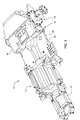
- Fig. 1 is a simplified side view of a vehicle component configuration embodying the invention
- Fig. 2 is an enlarged sectional view of a portion of Fig. 1 ;
- Fig. 3 is perspective view of the vehicle component configuration of Fig. 1 .
- a vehicle 10 such as a tractor, includes a frame 12 which supports an engine 14, a transmission housing 16 which encloses a transmission 17, a rear axle housing 18, a seat platform 20 and a seat 22.
- a drive line 24 transmits power from the rear end of the engine 14 to the front end of the transmission.
- the driveshaft 24 has a front end 26 coupled to the engine 14 and a rear end 28 coupled to the transmission 17.
- the frame 12 includes a lower midframe 30 which is connected between the engine 14 and the transmission housing 16, and an upper seat frame 32 which is positioned behind and higher than the midframe 30 and above the transmission housing 16.
- the seat platform 20 and the seat 22 are supported above the seat frame 32.
- the midframe 30 also supports a floor 40 which extends from a front end adjacent the rear end of the engine 14 to a rear end which overlays a front portion of the transmission housing 16.
- the floor 40 is mounted to a platform structure (not shown) which is mounted to the midframe 30 in the front and to the rear axle housing 18 at the rear.
- the drive line front end 26 is lower than the drive line rear end 28.
- the driveshaft 24 has an axis 50 which is oriented at an angle of about 1.5 degrees with respect to the horizontal plane 52.
- the transmission housing 16 is positioned under the seat 22, and rearward of a normal operator foot position and immediately adjacent to the rear axle housing 18.
- the engine 14 has an output shaft 15 which is parallel to the driveshaft 24, and the transmission 17 has an input shaft 54 which is parallel to the driveshaft 24.
- the axis of engine output shaft 15 is also oriented approximately 1.5 degrees with respect to a horizontal plane, as is the transmission input shaft 54, so that both the engine 14 and the transmission housing 16 have front ends which are tilted downward.
- This vehicle component configuration provides adequate clearance for the natural position of the heels of the operator. Only a very small tunnel is required because the transmission is placed in close proximity to the rear axle underneath the seated position of the operator- rearward of the natural position to the rear of the heels of the operator.
- the transmission and engine are tilted down approximately 1.5 deg. with the relation to the ground so the front of the transmission is moved closer to the ground. This also allows the seat and operator to be moved closer to the ground.
- the shaft centers of the engine and the transmission are both tilted the same angle to allow only the passage of a small diameter driveshaft between the engine and transmission.
- Driveshaft u-joints are not required allowing for a smaller diameter drive shaft allowing for a substantially flat floor. This greatly improve the ease of egress and exit and still maintains the low operating position of the operator and the short wheelbase of the tractor.
- the result is a more compact tractor package which allows operation in low clearance areas such as orchards, low barns, and livestock sheds.
- This invention increases the ease of getting on and off the vehicle or tractor, and is applicable to tractors with and without cabs. Feet can be spaced at any width for comfort of the operator.
Landscapes
- Engineering & Computer Science (AREA)
- Chemical & Material Sciences (AREA)
- Combustion & Propulsion (AREA)
- Transportation (AREA)
- Mechanical Engineering (AREA)
- Body Structure For Vehicles (AREA)
- Arrangement And Driving Of Transmission Devices (AREA)
Abstract
Description
- The present invention relates to a vehicle having an engine, a transmission, a driveshaft, a rear axle housing, a frame and a seat supported on the frame, the driveshaft having a front end coupled to the engine and a rear end coupled to the transmission, wherein the transmission being positioned under the seat.
- Tractor operators want to be seated as low as possible in the tractor cab so they can avoid overhead obstructions. For this reason many current agricultural tractors have a cab floor which has lower floor parts arranged on either side of a central tunnel which covers drive line or transmission parts. The lower floor parts allow an operator to sit lower. Tractor operators also want to have no or minimal obstructions to their feet on the cab floor during mounting, dismounting, and operation. Some tractors have transmission components which are too wide to be contained in a central tunnel which can be straddled by the operator. In such tractors, the cab floor either side of the transmission and the seat must be raised to move the operator high enough to avoid the need to straddle the transmission. This results in the operator being placed higher from the ground than desired. It is desired to provide a tractor design which results both in a low operator position and a minimal foot obstruction.
- Accordingly, an object of this invention is to provide a tractor design which results both in a low operator position and a minimal foot obstruction.
- The object of the invention will be achieved by the teachings of claim 1. Further advantageous embodiments are defined within the subclaims.
- According to the invention a vehicle of the above mentioned type is provided with a transmission wherein the transmission is positioned under the seat rearward of a normal operator foot position and immediately adjacent to the rear axle housing; and the front end of the driveshaft being lower than the rear end of the driveshaft.
- The driveshaft extends along a driveshaft axis which is oriented approximately 1.5 degrees with respect to a horizontal plane. The engine has an output shaft which is parallel to the driveshaft, and the transmission has an input shaft which is parallel to the driveshaft.
-
Fig. 1 is a simplified side view of a vehicle component configuration embodying the invention; -
Fig. 2 is an enlarged sectional view of a portion ofFig. 1 ; and -
Fig. 3 is perspective view of the vehicle component configuration ofFig. 1 . - Referring to
Figs. 1-3 , avehicle 10, such as a tractor, includes aframe 12 which supports anengine 14, atransmission housing 16 which encloses atransmission 17, arear axle housing 18, aseat platform 20 and aseat 22. Adrive line 24 transmits power from the rear end of theengine 14 to the front end of the transmission. Thedriveshaft 24 has afront end 26 coupled to theengine 14 and arear end 28 coupled to thetransmission 17. - The
frame 12 includes alower midframe 30 which is connected between theengine 14 and thetransmission housing 16, and anupper seat frame 32 which is positioned behind and higher than themidframe 30 and above thetransmission housing 16. Theseat platform 20 and theseat 22 are supported above theseat frame 32. Themidframe 30 also supports afloor 40 which extends from a front end adjacent the rear end of theengine 14 to a rear end which overlays a front portion of thetransmission housing 16. Thefloor 40 is mounted to a platform structure (not shown) which is mounted to themidframe 30 in the front and to therear axle housing 18 at the rear. - As best seen in
Figs. 1 and2 , the driveline front end 26 is lower than the drive linerear end 28. Preferably, thedriveshaft 24 has anaxis 50 which is oriented at an angle of about 1.5 degrees with respect to thehorizontal plane 52. As a result, thetransmission housing 16 is positioned under theseat 22, and rearward of a normal operator foot position and immediately adjacent to therear axle housing 18. Preferably, theengine 14 has anoutput shaft 15 which is parallel to thedriveshaft 24, and thetransmission 17 has aninput shaft 54 which is parallel to thedriveshaft 24. The axis ofengine output shaft 15 is also oriented approximately 1.5 degrees with respect to a horizontal plane, as is thetransmission input shaft 54, so that both theengine 14 and thetransmission housing 16 have front ends which are tilted downward. - This vehicle component configuration provides adequate clearance for the natural position of the heels of the operator. Only a very small tunnel is required because the transmission is placed in close proximity to the rear axle underneath the seated position of the operator- rearward of the natural position to the rear of the heels of the operator. The transmission and engine are tilted down approximately 1.5 deg. with the relation to the ground so the front of the transmission is moved closer to the ground. This also allows the seat and operator to be moved closer to the ground. The shaft centers of the engine and the transmission are both tilted the same angle to allow only the passage of a small diameter driveshaft between the engine and transmission. Driveshaft u-joints are not required allowing for a smaller diameter drive shaft allowing for a substantially flat floor. This greatly improve the ease of egress and exit and still maintains the low operating position of the operator and the short wheelbase of the tractor.
- The result is a more compact tractor package which allows operation in low clearance areas such as orchards, low barns, and livestock sheds. This invention increases the ease of getting on and off the vehicle or tractor, and is applicable to tractors with and without cabs. Feet can be spaced at any width for comfort of the operator.
- While the present invention has been described in conjunction with a specific embodiment, it is understood that many alternatives, modifications and variations will be apparent to those skilled in the art in light of the foregoing description.
- Accordingly, this invention is intended to embrace all such alternatives, modifications and variations which fall within the spirit and scope of the appended claims.
Claims (3)
- In a vehicle (10) having an engine (14), a transmission (17), a driveshaft (24), a rear axle housing (18), a frame (12) and a seat (22) supported on the frame (12), the driveshaft (24) having a front end (26) coupled to the engine (14) and a rear end (28) coupled to the transmission (17), wherein the transmission (17) being positioned under the seat (22), characterized in that the transmission (17) is positioned under the seat (22) rearward of a normal operator foot position and immediately adjacent to the rear axle housing (18); and the front end (26) of the driveshaft (24) being lower than the rear end (28) of the driveshaft (24).
- The vehicle of claim 1, wherein: the driveshaft (24) extends along a driveshaft axis (50) which is oriented approximately 1.5 degrees with respect to a horizontal plane (52).
- The vehicle of claim 1 or 2, wherein: the engine (14) has an output shaft axis which is oriented approximately 1.5 degrees with respect to the horizontal plane (52); and the transmission (17) has an input shaft axis which is oriented approximately 1.5 degrees with respect to the horizontal plane (52), both the engine (14) and a transmission housing (16) having front ends which are tilted downward.
Applications Claiming Priority (1)
| Application Number | Priority Date | Filing Date | Title |
|---|---|---|---|
| US11/953,107 US20090146458A1 (en) | 2007-12-10 | 2007-12-10 | Vehicle component configuration |
Publications (2)
| Publication Number | Publication Date |
|---|---|
| EP2072314A2 true EP2072314A2 (en) | 2009-06-24 |
| EP2072314A3 EP2072314A3 (en) | 2010-11-17 |
Family
ID=40433757
Family Applications (1)
| Application Number | Title | Priority Date | Filing Date |
|---|---|---|---|
| EP08170226A Withdrawn EP2072314A3 (en) | 2007-12-10 | 2008-11-28 | Vehicle |
Country Status (4)
| Country | Link |
|---|---|
| US (1) | US20090146458A1 (en) |
| EP (1) | EP2072314A3 (en) |
| CN (1) | CN101486312A (en) |
| BR (1) | BRPI0805230A2 (en) |
Family Cites Families (9)
| Publication number | Priority date | Publication date | Assignee | Title |
|---|---|---|---|---|
| JPS6025821A (en) * | 1983-07-22 | 1985-02-08 | Iseki & Co Ltd | Supporting device of engine, in tractor |
| JPH078612B2 (en) * | 1986-07-30 | 1995-02-01 | 本田技研工業株式会社 | Tractor power transmission device |
| US4804060A (en) * | 1986-11-04 | 1989-02-14 | Kubota Limited | Frame type tractor |
| KR910008036B1 (en) * | 1987-11-04 | 1991-10-07 | 구보다 뎃꼬오 가부시끼가이샤 | Transmission structure of the tractor propulsion shaft |
| JPH075029B2 (en) * | 1987-12-29 | 1995-01-25 | 株式会社神崎高級工機製作所 | Self-propelled work vehicle transmission |
| JP3445339B2 (en) * | 1993-11-25 | 2003-09-08 | 株式会社 神崎高級工機製作所 | Four-wheel drive transmission for work vehicles |
| JP2001018671A (en) * | 1999-07-08 | 2001-01-23 | Kanzaki Kokyukoki Mfg Co Ltd | Motive power take-off device for tractor |
| JP3708001B2 (en) * | 2000-07-25 | 2005-10-19 | 株式会社クボタ | Power take-out structure of work vehicle |
| DE60227126D1 (en) * | 2001-03-26 | 2008-07-31 | Kanzaki Kokyukoki Mfg Co Ltd | Transmission arrangement with power take-off for a work vehicle |
-
2007
- 2007-12-10 US US11/953,107 patent/US20090146458A1/en not_active Abandoned
-
2008
- 2008-11-26 BR BRPI0805230-1A patent/BRPI0805230A2/en not_active IP Right Cessation
- 2008-11-28 EP EP08170226A patent/EP2072314A3/en not_active Withdrawn
- 2008-12-05 CN CNA2008101824094A patent/CN101486312A/en active Pending
Also Published As
| Publication number | Publication date |
|---|---|
| EP2072314A3 (en) | 2010-11-17 |
| US20090146458A1 (en) | 2009-06-11 |
| CN101486312A (en) | 2009-07-22 |
| BRPI0805230A2 (en) | 2011-10-18 |
Similar Documents
| Publication | Publication Date | Title |
|---|---|---|
| US7861502B1 (en) | Top adjusting linkage for leveling a mower deck | |
| CA2307926C (en) | Multi-functional self-propelled farm tractor | |
| CA2512505A1 (en) | Discharge arrangement of an agricultural harvesting machine | |
| US20090146458A1 (en) | Vehicle component configuration | |
| US9125340B2 (en) | Ride-on lawn mower | |
| EP2825016B1 (en) | Cutting deck lift system for lawn mower | |
| JP5658019B2 (en) | Farm tractor | |
| JP4914385B2 (en) | Combine | |
| JP3294752B2 (en) | Combine control tower structure | |
| JP5929888B2 (en) | Combine | |
| US6875103B2 (en) | Apparatus and method for installing and removing a harvesting combine rotor | |
| US20200346695A1 (en) | Grounds maintenance vehicle with flip-up implement drive cover | |
| CN110617138B (en) | Combine harvester, semi-feeding combine harvester and harvester | |
| US7175520B2 (en) | Cab arrangement for harvesting combine | |
| JP3534638B2 (en) | Driving unit structure of combine | |
| CN108781768B (en) | Control part structure | |
| CN108496532B (en) | Harvester | |
| KR20240129568A (en) | Working machine | |
| JP7178943B2 (en) | combine | |
| CN118511726A (en) | Operating machinery | |
| JP3047888B2 (en) | Cabin such as combine | |
| JP2956416B2 (en) | Left and right slide type harvester | |
| JP2004313118A (en) | Cabin structure of combine | |
| JPH0325533Y2 (en) | ||
| JP3385571B2 (en) | Combine harvester |
Legal Events
| Date | Code | Title | Description |
|---|---|---|---|
| PUAI | Public reference made under article 153(3) epc to a published international application that has entered the european phase |
Free format text: ORIGINAL CODE: 0009012 |
|
| AK | Designated contracting states |
Kind code of ref document: A2 Designated state(s): AT BE BG CH CY CZ DE DK EE ES FI FR GB GR HR HU IE IS IT LI LT LU LV MC MT NL NO PL PT RO SE SI SK TR |
|
| AX | Request for extension of the european patent |
Extension state: AL BA MK RS |
|
| PUAL | Search report despatched |
Free format text: ORIGINAL CODE: 0009013 |
|
| AK | Designated contracting states |
Kind code of ref document: A3 Designated state(s): AT BE BG CH CY CZ DE DK EE ES FI FR GB GR HR HU IE IS IT LI LT LU LV MC MT NL NO PL PT RO SE SI SK TR |
|
| AX | Request for extension of the european patent |
Extension state: AL BA MK RS |
|
| RIC1 | Information provided on ipc code assigned before grant |
Ipc: B60K 5/02 20060101ALI20101008BHEP Ipc: B60K 17/04 20060101ALI20101008BHEP Ipc: B60K 17/22 20060101AFI20090319BHEP |
|
| STAA | Information on the status of an ep patent application or granted ep patent |
Free format text: STATUS: THE APPLICATION HAS BEEN WITHDRAWN |
|
| 18W | Application withdrawn |
Effective date: 20110414 |