EP2072311A1 - Drive system for hybrid vehicle - Google Patents
Drive system for hybrid vehicle Download PDFInfo
- Publication number
- EP2072311A1 EP2072311A1 EP07076100A EP07076100A EP2072311A1 EP 2072311 A1 EP2072311 A1 EP 2072311A1 EP 07076100 A EP07076100 A EP 07076100A EP 07076100 A EP07076100 A EP 07076100A EP 2072311 A1 EP2072311 A1 EP 2072311A1
- Authority
- EP
- European Patent Office
- Prior art keywords
- drive system
- drive
- power
- electric machines
- transmission
- Prior art date
- Legal status (The legal status is an assumption and is not a legal conclusion. Google has not performed a legal analysis and makes no representation as to the accuracy of the status listed.)
- Withdrawn
Links
Images


Classifications
-
- B—PERFORMING OPERATIONS; TRANSPORTING
- B60—VEHICLES IN GENERAL
- B60K—ARRANGEMENT OR MOUNTING OF PROPULSION UNITS OR OF TRANSMISSIONS IN VEHICLES; ARRANGEMENT OR MOUNTING OF PLURAL DIVERSE PRIME-MOVERS IN VEHICLES; AUXILIARY DRIVES FOR VEHICLES; INSTRUMENTATION OR DASHBOARDS FOR VEHICLES; ARRANGEMENTS IN CONNECTION WITH COOLING, AIR INTAKE, GAS EXHAUST OR FUEL SUPPLY OF PROPULSION UNITS IN VEHICLES
- B60K6/00—Arrangement or mounting of plural diverse prime-movers for mutual or common propulsion, e.g. hybrid propulsion systems comprising electric motors and internal combustion engines ; Control systems therefor, i.e. systems controlling two or more prime movers, or controlling one of these prime movers and any of the transmission, drive or drive units Informative references: mechanical gearings with secondary electric drive F16H3/72; arrangements for handling mechanical energy structurally associated with the dynamo-electric machine H02K7/00; machines comprising structurally interrelated motor and generator parts H02K51/00; dynamo-electric machines not otherwise provided for in H02K see H02K99/00
- B60K6/20—Arrangement or mounting of plural diverse prime-movers for mutual or common propulsion, e.g. hybrid propulsion systems comprising electric motors and internal combustion engines ; Control systems therefor, i.e. systems controlling two or more prime movers, or controlling one of these prime movers and any of the transmission, drive or drive units Informative references: mechanical gearings with secondary electric drive F16H3/72; arrangements for handling mechanical energy structurally associated with the dynamo-electric machine H02K7/00; machines comprising structurally interrelated motor and generator parts H02K51/00; dynamo-electric machines not otherwise provided for in H02K see H02K99/00 the prime-movers consisting of electric motors and internal combustion engines, e.g. HEVs
- B60K6/22—Arrangement or mounting of plural diverse prime-movers for mutual or common propulsion, e.g. hybrid propulsion systems comprising electric motors and internal combustion engines ; Control systems therefor, i.e. systems controlling two or more prime movers, or controlling one of these prime movers and any of the transmission, drive or drive units Informative references: mechanical gearings with secondary electric drive F16H3/72; arrangements for handling mechanical energy structurally associated with the dynamo-electric machine H02K7/00; machines comprising structurally interrelated motor and generator parts H02K51/00; dynamo-electric machines not otherwise provided for in H02K see H02K99/00 the prime-movers consisting of electric motors and internal combustion engines, e.g. HEVs characterised by apparatus, components or means specially adapted for HEVs
- B60K6/26—Arrangement or mounting of plural diverse prime-movers for mutual or common propulsion, e.g. hybrid propulsion systems comprising electric motors and internal combustion engines ; Control systems therefor, i.e. systems controlling two or more prime movers, or controlling one of these prime movers and any of the transmission, drive or drive units Informative references: mechanical gearings with secondary electric drive F16H3/72; arrangements for handling mechanical energy structurally associated with the dynamo-electric machine H02K7/00; machines comprising structurally interrelated motor and generator parts H02K51/00; dynamo-electric machines not otherwise provided for in H02K see H02K99/00 the prime-movers consisting of electric motors and internal combustion engines, e.g. HEVs characterised by apparatus, components or means specially adapted for HEVs characterised by the motors or the generators
-
- B—PERFORMING OPERATIONS; TRANSPORTING
- B60—VEHICLES IN GENERAL
- B60K—ARRANGEMENT OR MOUNTING OF PROPULSION UNITS OR OF TRANSMISSIONS IN VEHICLES; ARRANGEMENT OR MOUNTING OF PLURAL DIVERSE PRIME-MOVERS IN VEHICLES; AUXILIARY DRIVES FOR VEHICLES; INSTRUMENTATION OR DASHBOARDS FOR VEHICLES; ARRANGEMENTS IN CONNECTION WITH COOLING, AIR INTAKE, GAS EXHAUST OR FUEL SUPPLY OF PROPULSION UNITS IN VEHICLES
- B60K6/00—Arrangement or mounting of plural diverse prime-movers for mutual or common propulsion, e.g. hybrid propulsion systems comprising electric motors and internal combustion engines ; Control systems therefor, i.e. systems controlling two or more prime movers, or controlling one of these prime movers and any of the transmission, drive or drive units Informative references: mechanical gearings with secondary electric drive F16H3/72; arrangements for handling mechanical energy structurally associated with the dynamo-electric machine H02K7/00; machines comprising structurally interrelated motor and generator parts H02K51/00; dynamo-electric machines not otherwise provided for in H02K see H02K99/00
- B60K6/20—Arrangement or mounting of plural diverse prime-movers for mutual or common propulsion, e.g. hybrid propulsion systems comprising electric motors and internal combustion engines ; Control systems therefor, i.e. systems controlling two or more prime movers, or controlling one of these prime movers and any of the transmission, drive or drive units Informative references: mechanical gearings with secondary electric drive F16H3/72; arrangements for handling mechanical energy structurally associated with the dynamo-electric machine H02K7/00; machines comprising structurally interrelated motor and generator parts H02K51/00; dynamo-electric machines not otherwise provided for in H02K see H02K99/00 the prime-movers consisting of electric motors and internal combustion engines, e.g. HEVs
- B60K6/22—Arrangement or mounting of plural diverse prime-movers for mutual or common propulsion, e.g. hybrid propulsion systems comprising electric motors and internal combustion engines ; Control systems therefor, i.e. systems controlling two or more prime movers, or controlling one of these prime movers and any of the transmission, drive or drive units Informative references: mechanical gearings with secondary electric drive F16H3/72; arrangements for handling mechanical energy structurally associated with the dynamo-electric machine H02K7/00; machines comprising structurally interrelated motor and generator parts H02K51/00; dynamo-electric machines not otherwise provided for in H02K see H02K99/00 the prime-movers consisting of electric motors and internal combustion engines, e.g. HEVs characterised by apparatus, components or means specially adapted for HEVs
- B60K6/36—Arrangement or mounting of plural diverse prime-movers for mutual or common propulsion, e.g. hybrid propulsion systems comprising electric motors and internal combustion engines ; Control systems therefor, i.e. systems controlling two or more prime movers, or controlling one of these prime movers and any of the transmission, drive or drive units Informative references: mechanical gearings with secondary electric drive F16H3/72; arrangements for handling mechanical energy structurally associated with the dynamo-electric machine H02K7/00; machines comprising structurally interrelated motor and generator parts H02K51/00; dynamo-electric machines not otherwise provided for in H02K see H02K99/00 the prime-movers consisting of electric motors and internal combustion engines, e.g. HEVs characterised by apparatus, components or means specially adapted for HEVs characterised by the transmission gearings
- B60K6/365—Arrangement or mounting of plural diverse prime-movers for mutual or common propulsion, e.g. hybrid propulsion systems comprising electric motors and internal combustion engines ; Control systems therefor, i.e. systems controlling two or more prime movers, or controlling one of these prime movers and any of the transmission, drive or drive units Informative references: mechanical gearings with secondary electric drive F16H3/72; arrangements for handling mechanical energy structurally associated with the dynamo-electric machine H02K7/00; machines comprising structurally interrelated motor and generator parts H02K51/00; dynamo-electric machines not otherwise provided for in H02K see H02K99/00 the prime-movers consisting of electric motors and internal combustion engines, e.g. HEVs characterised by apparatus, components or means specially adapted for HEVs characterised by the transmission gearings with the gears having orbital motion
-
- B—PERFORMING OPERATIONS; TRANSPORTING
- B60—VEHICLES IN GENERAL
- B60K—ARRANGEMENT OR MOUNTING OF PROPULSION UNITS OR OF TRANSMISSIONS IN VEHICLES; ARRANGEMENT OR MOUNTING OF PLURAL DIVERSE PRIME-MOVERS IN VEHICLES; AUXILIARY DRIVES FOR VEHICLES; INSTRUMENTATION OR DASHBOARDS FOR VEHICLES; ARRANGEMENTS IN CONNECTION WITH COOLING, AIR INTAKE, GAS EXHAUST OR FUEL SUPPLY OF PROPULSION UNITS IN VEHICLES
- B60K6/00—Arrangement or mounting of plural diverse prime-movers for mutual or common propulsion, e.g. hybrid propulsion systems comprising electric motors and internal combustion engines ; Control systems therefor, i.e. systems controlling two or more prime movers, or controlling one of these prime movers and any of the transmission, drive or drive units Informative references: mechanical gearings with secondary electric drive F16H3/72; arrangements for handling mechanical energy structurally associated with the dynamo-electric machine H02K7/00; machines comprising structurally interrelated motor and generator parts H02K51/00; dynamo-electric machines not otherwise provided for in H02K see H02K99/00
- B60K6/20—Arrangement or mounting of plural diverse prime-movers for mutual or common propulsion, e.g. hybrid propulsion systems comprising electric motors and internal combustion engines ; Control systems therefor, i.e. systems controlling two or more prime movers, or controlling one of these prime movers and any of the transmission, drive or drive units Informative references: mechanical gearings with secondary electric drive F16H3/72; arrangements for handling mechanical energy structurally associated with the dynamo-electric machine H02K7/00; machines comprising structurally interrelated motor and generator parts H02K51/00; dynamo-electric machines not otherwise provided for in H02K see H02K99/00 the prime-movers consisting of electric motors and internal combustion engines, e.g. HEVs
- B60K6/42—Arrangement or mounting of plural diverse prime-movers for mutual or common propulsion, e.g. hybrid propulsion systems comprising electric motors and internal combustion engines ; Control systems therefor, i.e. systems controlling two or more prime movers, or controlling one of these prime movers and any of the transmission, drive or drive units Informative references: mechanical gearings with secondary electric drive F16H3/72; arrangements for handling mechanical energy structurally associated with the dynamo-electric machine H02K7/00; machines comprising structurally interrelated motor and generator parts H02K51/00; dynamo-electric machines not otherwise provided for in H02K see H02K99/00 the prime-movers consisting of electric motors and internal combustion engines, e.g. HEVs characterised by the architecture of the hybrid electric vehicle
- B60K6/44—Series-parallel type
- B60K6/445—Differential gearing distribution type
-
- B—PERFORMING OPERATIONS; TRANSPORTING
- B60—VEHICLES IN GENERAL
- B60K—ARRANGEMENT OR MOUNTING OF PROPULSION UNITS OR OF TRANSMISSIONS IN VEHICLES; ARRANGEMENT OR MOUNTING OF PLURAL DIVERSE PRIME-MOVERS IN VEHICLES; AUXILIARY DRIVES FOR VEHICLES; INSTRUMENTATION OR DASHBOARDS FOR VEHICLES; ARRANGEMENTS IN CONNECTION WITH COOLING, AIR INTAKE, GAS EXHAUST OR FUEL SUPPLY OF PROPULSION UNITS IN VEHICLES
- B60K6/00—Arrangement or mounting of plural diverse prime-movers for mutual or common propulsion, e.g. hybrid propulsion systems comprising electric motors and internal combustion engines ; Control systems therefor, i.e. systems controlling two or more prime movers, or controlling one of these prime movers and any of the transmission, drive or drive units Informative references: mechanical gearings with secondary electric drive F16H3/72; arrangements for handling mechanical energy structurally associated with the dynamo-electric machine H02K7/00; machines comprising structurally interrelated motor and generator parts H02K51/00; dynamo-electric machines not otherwise provided for in H02K see H02K99/00
- B60K6/20—Arrangement or mounting of plural diverse prime-movers for mutual or common propulsion, e.g. hybrid propulsion systems comprising electric motors and internal combustion engines ; Control systems therefor, i.e. systems controlling two or more prime movers, or controlling one of these prime movers and any of the transmission, drive or drive units Informative references: mechanical gearings with secondary electric drive F16H3/72; arrangements for handling mechanical energy structurally associated with the dynamo-electric machine H02K7/00; machines comprising structurally interrelated motor and generator parts H02K51/00; dynamo-electric machines not otherwise provided for in H02K see H02K99/00 the prime-movers consisting of electric motors and internal combustion engines, e.g. HEVs
- B60K6/42—Arrangement or mounting of plural diverse prime-movers for mutual or common propulsion, e.g. hybrid propulsion systems comprising electric motors and internal combustion engines ; Control systems therefor, i.e. systems controlling two or more prime movers, or controlling one of these prime movers and any of the transmission, drive or drive units Informative references: mechanical gearings with secondary electric drive F16H3/72; arrangements for handling mechanical energy structurally associated with the dynamo-electric machine H02K7/00; machines comprising structurally interrelated motor and generator parts H02K51/00; dynamo-electric machines not otherwise provided for in H02K see H02K99/00 the prime-movers consisting of electric motors and internal combustion engines, e.g. HEVs characterised by the architecture of the hybrid electric vehicle
- B60K6/44—Series-parallel type
- B60K6/448—Electrical distribution type
-
- B—PERFORMING OPERATIONS; TRANSPORTING
- B60—VEHICLES IN GENERAL
- B60L—PROPULSION OF ELECTRICALLY-PROPELLED VEHICLES; SUPPLYING ELECTRIC POWER FOR AUXILIARY EQUIPMENT OF ELECTRICALLY-PROPELLED VEHICLES; ELECTRODYNAMIC BRAKE SYSTEMS FOR VEHICLES IN GENERAL; MAGNETIC SUSPENSION OR LEVITATION FOR VEHICLES; MONITORING OPERATING VARIABLES OF ELECTRICALLY-PROPELLED VEHICLES; ELECTRIC SAFETY DEVICES FOR ELECTRICALLY-PROPELLED VEHICLES
- B60L15/00—Methods, circuits, or devices for controlling the traction-motor speed of electrically-propelled vehicles
- B60L15/20—Methods, circuits, or devices for controlling the traction-motor speed of electrically-propelled vehicles for control of the vehicle or its driving motor to achieve a desired performance, e.g. speed, torque, programmed variation of speed
- B60L15/2009—Methods, circuits, or devices for controlling the traction-motor speed of electrically-propelled vehicles for control of the vehicle or its driving motor to achieve a desired performance, e.g. speed, torque, programmed variation of speed for braking
-
- B—PERFORMING OPERATIONS; TRANSPORTING
- B60—VEHICLES IN GENERAL
- B60L—PROPULSION OF ELECTRICALLY-PROPELLED VEHICLES; SUPPLYING ELECTRIC POWER FOR AUXILIARY EQUIPMENT OF ELECTRICALLY-PROPELLED VEHICLES; ELECTRODYNAMIC BRAKE SYSTEMS FOR VEHICLES IN GENERAL; MAGNETIC SUSPENSION OR LEVITATION FOR VEHICLES; MONITORING OPERATING VARIABLES OF ELECTRICALLY-PROPELLED VEHICLES; ELECTRIC SAFETY DEVICES FOR ELECTRICALLY-PROPELLED VEHICLES
- B60L50/00—Electric propulsion with power supplied within the vehicle
- B60L50/10—Electric propulsion with power supplied within the vehicle using propulsion power supplied by engine-driven generators, e.g. generators driven by combustion engines
- B60L50/16—Electric propulsion with power supplied within the vehicle using propulsion power supplied by engine-driven generators, e.g. generators driven by combustion engines with provision for separate direct mechanical propulsion
-
- B—PERFORMING OPERATIONS; TRANSPORTING
- B60—VEHICLES IN GENERAL
- B60L—PROPULSION OF ELECTRICALLY-PROPELLED VEHICLES; SUPPLYING ELECTRIC POWER FOR AUXILIARY EQUIPMENT OF ELECTRICALLY-PROPELLED VEHICLES; ELECTRODYNAMIC BRAKE SYSTEMS FOR VEHICLES IN GENERAL; MAGNETIC SUSPENSION OR LEVITATION FOR VEHICLES; MONITORING OPERATING VARIABLES OF ELECTRICALLY-PROPELLED VEHICLES; ELECTRIC SAFETY DEVICES FOR ELECTRICALLY-PROPELLED VEHICLES
- B60L50/00—Electric propulsion with power supplied within the vehicle
- B60L50/50—Electric propulsion with power supplied within the vehicle using propulsion power supplied by batteries or fuel cells
- B60L50/60—Electric propulsion with power supplied within the vehicle using propulsion power supplied by batteries or fuel cells using power supplied by batteries
- B60L50/61—Electric propulsion with power supplied within the vehicle using propulsion power supplied by batteries or fuel cells using power supplied by batteries by batteries charged by engine-driven generators, e.g. series hybrid electric vehicles
-
- B—PERFORMING OPERATIONS; TRANSPORTING
- B60—VEHICLES IN GENERAL
- B60L—PROPULSION OF ELECTRICALLY-PROPELLED VEHICLES; SUPPLYING ELECTRIC POWER FOR AUXILIARY EQUIPMENT OF ELECTRICALLY-PROPELLED VEHICLES; ELECTRODYNAMIC BRAKE SYSTEMS FOR VEHICLES IN GENERAL; MAGNETIC SUSPENSION OR LEVITATION FOR VEHICLES; MONITORING OPERATING VARIABLES OF ELECTRICALLY-PROPELLED VEHICLES; ELECTRIC SAFETY DEVICES FOR ELECTRICALLY-PROPELLED VEHICLES
- B60L7/00—Electrodynamic brake systems for vehicles in general
- B60L7/10—Dynamic electric regenerative braking
- B60L7/14—Dynamic electric regenerative braking for vehicles propelled by ac motors
-
- B—PERFORMING OPERATIONS; TRANSPORTING
- B60—VEHICLES IN GENERAL
- B60K—ARRANGEMENT OR MOUNTING OF PROPULSION UNITS OR OF TRANSMISSIONS IN VEHICLES; ARRANGEMENT OR MOUNTING OF PLURAL DIVERSE PRIME-MOVERS IN VEHICLES; AUXILIARY DRIVES FOR VEHICLES; INSTRUMENTATION OR DASHBOARDS FOR VEHICLES; ARRANGEMENTS IN CONNECTION WITH COOLING, AIR INTAKE, GAS EXHAUST OR FUEL SUPPLY OF PROPULSION UNITS IN VEHICLES
- B60K6/00—Arrangement or mounting of plural diverse prime-movers for mutual or common propulsion, e.g. hybrid propulsion systems comprising electric motors and internal combustion engines ; Control systems therefor, i.e. systems controlling two or more prime movers, or controlling one of these prime movers and any of the transmission, drive or drive units Informative references: mechanical gearings with secondary electric drive F16H3/72; arrangements for handling mechanical energy structurally associated with the dynamo-electric machine H02K7/00; machines comprising structurally interrelated motor and generator parts H02K51/00; dynamo-electric machines not otherwise provided for in H02K see H02K99/00
- B60K6/20—Arrangement or mounting of plural diverse prime-movers for mutual or common propulsion, e.g. hybrid propulsion systems comprising electric motors and internal combustion engines ; Control systems therefor, i.e. systems controlling two or more prime movers, or controlling one of these prime movers and any of the transmission, drive or drive units Informative references: mechanical gearings with secondary electric drive F16H3/72; arrangements for handling mechanical energy structurally associated with the dynamo-electric machine H02K7/00; machines comprising structurally interrelated motor and generator parts H02K51/00; dynamo-electric machines not otherwise provided for in H02K see H02K99/00 the prime-movers consisting of electric motors and internal combustion engines, e.g. HEVs
- B60K6/22—Arrangement or mounting of plural diverse prime-movers for mutual or common propulsion, e.g. hybrid propulsion systems comprising electric motors and internal combustion engines ; Control systems therefor, i.e. systems controlling two or more prime movers, or controlling one of these prime movers and any of the transmission, drive or drive units Informative references: mechanical gearings with secondary electric drive F16H3/72; arrangements for handling mechanical energy structurally associated with the dynamo-electric machine H02K7/00; machines comprising structurally interrelated motor and generator parts H02K51/00; dynamo-electric machines not otherwise provided for in H02K see H02K99/00 the prime-movers consisting of electric motors and internal combustion engines, e.g. HEVs characterised by apparatus, components or means specially adapted for HEVs
- B60K6/26—Arrangement or mounting of plural diverse prime-movers for mutual or common propulsion, e.g. hybrid propulsion systems comprising electric motors and internal combustion engines ; Control systems therefor, i.e. systems controlling two or more prime movers, or controlling one of these prime movers and any of the transmission, drive or drive units Informative references: mechanical gearings with secondary electric drive F16H3/72; arrangements for handling mechanical energy structurally associated with the dynamo-electric machine H02K7/00; machines comprising structurally interrelated motor and generator parts H02K51/00; dynamo-electric machines not otherwise provided for in H02K see H02K99/00 the prime-movers consisting of electric motors and internal combustion engines, e.g. HEVs characterised by apparatus, components or means specially adapted for HEVs characterised by the motors or the generators
- B60K2006/262—Arrangement or mounting of plural diverse prime-movers for mutual or common propulsion, e.g. hybrid propulsion systems comprising electric motors and internal combustion engines ; Control systems therefor, i.e. systems controlling two or more prime movers, or controlling one of these prime movers and any of the transmission, drive or drive units Informative references: mechanical gearings with secondary electric drive F16H3/72; arrangements for handling mechanical energy structurally associated with the dynamo-electric machine H02K7/00; machines comprising structurally interrelated motor and generator parts H02K51/00; dynamo-electric machines not otherwise provided for in H02K see H02K99/00 the prime-movers consisting of electric motors and internal combustion engines, e.g. HEVs characterised by apparatus, components or means specially adapted for HEVs characterised by the motors or the generators the motor or generator are used as clutch, e.g. between engine and driveshaft
-
- B—PERFORMING OPERATIONS; TRANSPORTING
- B60—VEHICLES IN GENERAL
- B60L—PROPULSION OF ELECTRICALLY-PROPELLED VEHICLES; SUPPLYING ELECTRIC POWER FOR AUXILIARY EQUIPMENT OF ELECTRICALLY-PROPELLED VEHICLES; ELECTRODYNAMIC BRAKE SYSTEMS FOR VEHICLES IN GENERAL; MAGNETIC SUSPENSION OR LEVITATION FOR VEHICLES; MONITORING OPERATING VARIABLES OF ELECTRICALLY-PROPELLED VEHICLES; ELECTRIC SAFETY DEVICES FOR ELECTRICALLY-PROPELLED VEHICLES
- B60L2210/00—Converter types
- B60L2210/40—DC to AC converters
-
- B—PERFORMING OPERATIONS; TRANSPORTING
- B60—VEHICLES IN GENERAL
- B60L—PROPULSION OF ELECTRICALLY-PROPELLED VEHICLES; SUPPLYING ELECTRIC POWER FOR AUXILIARY EQUIPMENT OF ELECTRICALLY-PROPELLED VEHICLES; ELECTRODYNAMIC BRAKE SYSTEMS FOR VEHICLES IN GENERAL; MAGNETIC SUSPENSION OR LEVITATION FOR VEHICLES; MONITORING OPERATING VARIABLES OF ELECTRICALLY-PROPELLED VEHICLES; ELECTRIC SAFETY DEVICES FOR ELECTRICALLY-PROPELLED VEHICLES
- B60L2240/00—Control parameters of input or output; Target parameters
- B60L2240/10—Vehicle control parameters
- B60L2240/12—Speed
-
- B—PERFORMING OPERATIONS; TRANSPORTING
- B60—VEHICLES IN GENERAL
- B60L—PROPULSION OF ELECTRICALLY-PROPELLED VEHICLES; SUPPLYING ELECTRIC POWER FOR AUXILIARY EQUIPMENT OF ELECTRICALLY-PROPELLED VEHICLES; ELECTRODYNAMIC BRAKE SYSTEMS FOR VEHICLES IN GENERAL; MAGNETIC SUSPENSION OR LEVITATION FOR VEHICLES; MONITORING OPERATING VARIABLES OF ELECTRICALLY-PROPELLED VEHICLES; ELECTRIC SAFETY DEVICES FOR ELECTRICALLY-PROPELLED VEHICLES
- B60L2240/00—Control parameters of input or output; Target parameters
- B60L2240/40—Drive Train control parameters
- B60L2240/42—Drive Train control parameters related to electric machines
- B60L2240/421—Speed
-
- B—PERFORMING OPERATIONS; TRANSPORTING
- B60—VEHICLES IN GENERAL
- B60L—PROPULSION OF ELECTRICALLY-PROPELLED VEHICLES; SUPPLYING ELECTRIC POWER FOR AUXILIARY EQUIPMENT OF ELECTRICALLY-PROPELLED VEHICLES; ELECTRODYNAMIC BRAKE SYSTEMS FOR VEHICLES IN GENERAL; MAGNETIC SUSPENSION OR LEVITATION FOR VEHICLES; MONITORING OPERATING VARIABLES OF ELECTRICALLY-PROPELLED VEHICLES; ELECTRIC SAFETY DEVICES FOR ELECTRICALLY-PROPELLED VEHICLES
- B60L2240/00—Control parameters of input or output; Target parameters
- B60L2240/40—Drive Train control parameters
- B60L2240/42—Drive Train control parameters related to electric machines
- B60L2240/423—Torque
-
- B—PERFORMING OPERATIONS; TRANSPORTING
- B60—VEHICLES IN GENERAL
- B60L—PROPULSION OF ELECTRICALLY-PROPELLED VEHICLES; SUPPLYING ELECTRIC POWER FOR AUXILIARY EQUIPMENT OF ELECTRICALLY-PROPELLED VEHICLES; ELECTRODYNAMIC BRAKE SYSTEMS FOR VEHICLES IN GENERAL; MAGNETIC SUSPENSION OR LEVITATION FOR VEHICLES; MONITORING OPERATING VARIABLES OF ELECTRICALLY-PROPELLED VEHICLES; ELECTRIC SAFETY DEVICES FOR ELECTRICALLY-PROPELLED VEHICLES
- B60L2240/00—Control parameters of input or output; Target parameters
- B60L2240/40—Drive Train control parameters
- B60L2240/44—Drive Train control parameters related to combustion engines
- B60L2240/441—Speed
-
- B—PERFORMING OPERATIONS; TRANSPORTING
- B60—VEHICLES IN GENERAL
- B60L—PROPULSION OF ELECTRICALLY-PROPELLED VEHICLES; SUPPLYING ELECTRIC POWER FOR AUXILIARY EQUIPMENT OF ELECTRICALLY-PROPELLED VEHICLES; ELECTRODYNAMIC BRAKE SYSTEMS FOR VEHICLES IN GENERAL; MAGNETIC SUSPENSION OR LEVITATION FOR VEHICLES; MONITORING OPERATING VARIABLES OF ELECTRICALLY-PROPELLED VEHICLES; ELECTRIC SAFETY DEVICES FOR ELECTRICALLY-PROPELLED VEHICLES
- B60L2240/00—Control parameters of input or output; Target parameters
- B60L2240/40—Drive Train control parameters
- B60L2240/44—Drive Train control parameters related to combustion engines
- B60L2240/443—Torque
-
- F—MECHANICAL ENGINEERING; LIGHTING; HEATING; WEAPONS; BLASTING
- F16—ENGINEERING ELEMENTS AND UNITS; GENERAL MEASURES FOR PRODUCING AND MAINTAINING EFFECTIVE FUNCTIONING OF MACHINES OR INSTALLATIONS; THERMAL INSULATION IN GENERAL
- F16H—GEARING
- F16H37/00—Combinations of mechanical gearings, not provided for in groups F16H1/00 - F16H35/00
- F16H37/02—Combinations of mechanical gearings, not provided for in groups F16H1/00 - F16H35/00 comprising essentially only toothed or friction gearings
- F16H37/06—Combinations of mechanical gearings, not provided for in groups F16H1/00 - F16H35/00 comprising essentially only toothed or friction gearings with a plurality of driving or driven shafts; with arrangements for dividing torque between two or more intermediate shafts
- F16H37/08—Combinations of mechanical gearings, not provided for in groups F16H1/00 - F16H35/00 comprising essentially only toothed or friction gearings with a plurality of driving or driven shafts; with arrangements for dividing torque between two or more intermediate shafts with differential gearing
- F16H37/0833—Combinations of mechanical gearings, not provided for in groups F16H1/00 - F16H35/00 comprising essentially only toothed or friction gearings with a plurality of driving or driven shafts; with arrangements for dividing torque between two or more intermediate shafts with differential gearing with arrangements for dividing torque between two or more intermediate shafts, i.e. with two or more internal power paths
- F16H37/084—Combinations of mechanical gearings, not provided for in groups F16H1/00 - F16H35/00 comprising essentially only toothed or friction gearings with a plurality of driving or driven shafts; with arrangements for dividing torque between two or more intermediate shafts with differential gearing with arrangements for dividing torque between two or more intermediate shafts, i.e. with two or more internal power paths at least one power path being a continuously variable transmission, i.e. CVT
- F16H2037/088—Power split variators with summing differentials, with the input of the CVT connected or connectable to the input shaft
-
- Y—GENERAL TAGGING OF NEW TECHNOLOGICAL DEVELOPMENTS; GENERAL TAGGING OF CROSS-SECTIONAL TECHNOLOGIES SPANNING OVER SEVERAL SECTIONS OF THE IPC; TECHNICAL SUBJECTS COVERED BY FORMER USPC CROSS-REFERENCE ART COLLECTIONS [XRACs] AND DIGESTS
- Y02—TECHNOLOGIES OR APPLICATIONS FOR MITIGATION OR ADAPTATION AGAINST CLIMATE CHANGE
- Y02T—CLIMATE CHANGE MITIGATION TECHNOLOGIES RELATED TO TRANSPORTATION
- Y02T10/00—Road transport of goods or passengers
- Y02T10/60—Other road transportation technologies with climate change mitigation effect
- Y02T10/62—Hybrid vehicles
-
- Y—GENERAL TAGGING OF NEW TECHNOLOGICAL DEVELOPMENTS; GENERAL TAGGING OF CROSS-SECTIONAL TECHNOLOGIES SPANNING OVER SEVERAL SECTIONS OF THE IPC; TECHNICAL SUBJECTS COVERED BY FORMER USPC CROSS-REFERENCE ART COLLECTIONS [XRACs] AND DIGESTS
- Y02—TECHNOLOGIES OR APPLICATIONS FOR MITIGATION OR ADAPTATION AGAINST CLIMATE CHANGE
- Y02T—CLIMATE CHANGE MITIGATION TECHNOLOGIES RELATED TO TRANSPORTATION
- Y02T10/00—Road transport of goods or passengers
- Y02T10/60—Other road transportation technologies with climate change mitigation effect
- Y02T10/64—Electric machine technologies in electromobility
-
- Y—GENERAL TAGGING OF NEW TECHNOLOGICAL DEVELOPMENTS; GENERAL TAGGING OF CROSS-SECTIONAL TECHNOLOGIES SPANNING OVER SEVERAL SECTIONS OF THE IPC; TECHNICAL SUBJECTS COVERED BY FORMER USPC CROSS-REFERENCE ART COLLECTIONS [XRACs] AND DIGESTS
- Y02—TECHNOLOGIES OR APPLICATIONS FOR MITIGATION OR ADAPTATION AGAINST CLIMATE CHANGE
- Y02T—CLIMATE CHANGE MITIGATION TECHNOLOGIES RELATED TO TRANSPORTATION
- Y02T10/00—Road transport of goods or passengers
- Y02T10/60—Other road transportation technologies with climate change mitigation effect
- Y02T10/70—Energy storage systems for electromobility, e.g. batteries
-
- Y—GENERAL TAGGING OF NEW TECHNOLOGICAL DEVELOPMENTS; GENERAL TAGGING OF CROSS-SECTIONAL TECHNOLOGIES SPANNING OVER SEVERAL SECTIONS OF THE IPC; TECHNICAL SUBJECTS COVERED BY FORMER USPC CROSS-REFERENCE ART COLLECTIONS [XRACs] AND DIGESTS
- Y02—TECHNOLOGIES OR APPLICATIONS FOR MITIGATION OR ADAPTATION AGAINST CLIMATE CHANGE
- Y02T—CLIMATE CHANGE MITIGATION TECHNOLOGIES RELATED TO TRANSPORTATION
- Y02T10/00—Road transport of goods or passengers
- Y02T10/60—Other road transportation technologies with climate change mitigation effect
- Y02T10/7072—Electromobility specific charging systems or methods for batteries, ultracapacitors, supercapacitors or double-layer capacitors
-
- Y—GENERAL TAGGING OF NEW TECHNOLOGICAL DEVELOPMENTS; GENERAL TAGGING OF CROSS-SECTIONAL TECHNOLOGIES SPANNING OVER SEVERAL SECTIONS OF THE IPC; TECHNICAL SUBJECTS COVERED BY FORMER USPC CROSS-REFERENCE ART COLLECTIONS [XRACs] AND DIGESTS
- Y02—TECHNOLOGIES OR APPLICATIONS FOR MITIGATION OR ADAPTATION AGAINST CLIMATE CHANGE
- Y02T—CLIMATE CHANGE MITIGATION TECHNOLOGIES RELATED TO TRANSPORTATION
- Y02T10/00—Road transport of goods or passengers
- Y02T10/60—Other road transportation technologies with climate change mitigation effect
- Y02T10/72—Electric energy management in electromobility
Definitions
- the invention relates to a drive system, in particular to a drive system for a hybrid vehicle, provided with an engine and an electric machine.
- the engine and the electric machine are power sources that each have different characteristics and of which the driving power is used to run the vehicle in a combination that is optimal for the conditions.
- a first path includes a mechanical path that transmits mechanical power only.
- a second path includes two electric machines. Between these electrical machines, this path transmits electrical power only.
- the two drive paths are mechanically coupled downstream of the electrical machines, e.g. using a mechanical reduction device.
- the coupled paths go to the final drive.
- a first one of the electric machines functions as a generator, and a second one of the electric machines functions as a motor or vice versa.
- the motor and the generator are coupled via inverters.
- the inverter are coupled to the battery.
- the invention aims to lessen the above disadvantages.
- the invention provides for a drive system, in particular for a hybrid vehicle, comprising a power split device with associated drive paths, wherein at least one of the drive paths comprises two mechanically coupled electric machines that form a cascaded power split having both a mechanical and an electrical drive path.
- the dual air gap machine comprises a rotor, an interrotor and a stator that together form two mechanically integrated electric machines.
- Examples of such machines are disclosed in US5917248 , WO 0034066 , EP1154551A2 , WO03051660 and in Longya Xu, "A new breed of electric machines- basic analysis and applications of dual mechanical port electric machines," Proc. 8th Int. Conf. Electrical Machines and Systems, Nanjing, 2005, pp. 24-29 .
- the mechanically coupled electric machines may be used as an electric variator, i.e. as a unit that enforces a given speed difference across the input and output shaft of the drive path with the electrical machines.
- the two electric machines are also magnetically coupled, and are preferably part of an electric variable transmission such as for example disclosed by applicant in WO 03/075437 .
- a machine can e.g. be characterized as an electric variable transmission comprising an electromechanical converter provided with a primary shaft having a rotor mounted thereon, a secondary shaft having an interrotor mounted thereon, and a stator, fixedly mounted to the housing of the electromechanical converter wherein, viewed from the primary shaft in radial direction, the rotor, the interrotor and the stator are arranged concentrically relative to each other, and wherein the rotor and the stator are designed with one or more mono- or polyphase, electrically accessible windings, wherein the interrotor forms one whole both mechanically and electromagnetically, and is arranged as an conductor for the magnetic flux in tangential and radial direction, and wherein the pattern of magnetic poles in the magnetic flux conducting material on at least one side of the interrotor is free and can be varied during operation.
- the power split device in the drive system can be an input split type, an output split type, a compound split type or combinations of the above.
- the power split device is an output split device that is arranged to combine two power paths at the transmission output.
- Another option is the input split type, wherein the power split occurs at the input side of the transmission.
- Yet another option is the compound split configuration, where the power is split at the transmission input and again combined by a second power split device at the transmission output.
- the power split device may comprise a planetary gear, but may also comprise a hydraulic torque converter of suitable configuration.
- the invention also relates to a hybrid vehicle, comprising a drive system in any of the variants described above, as well as to the use of a dual air gap electric machine, in particular an electric variable transmission, in a drive path of a drive system with a power split device.
- the invention further relates to a method for transmission of power in a drive system, wherein the drive power is split into drive paths, and wherein the power in one of the drive paths is split again using two mechanically coupled, in particular mechanically integrated, and preferably also electromagnetically coupled electric machines. This way, the split path can be subdivided into both an electric and a mechanical drive path, thereby reducing the power requirements for the components in the electric drive path.
- Fig. 1 shows a drive system 1 for a hybrid vehicle.
- the hybrid vehicle may e.g. be an automobile that combines two motive power sources, such as an internal combustion engine and an electric motor.
- the drive system 1 comprises a power split device 2.
- the power split device is embodied as a planetary gear system.
- the power split device 2 is here embodied as an input split device that is arranged to split inut power.
- the transmission paths are split at the transmission entrance and are coupled at the transmission output.
- the input power for the power split device 2 here is generated by a combustion engine 3.
- a combustion engine may e.g. be an internal combustion engine, such as a Diesel motor or an Otto motor.
- the power split device 2 splits the torque generated by the engine into two drive paths that meet each other at a junction point 16 before a differential 17.
- a first path I that is shown in the top of the drawing transmits mechanical power only.
- a second path II which is shown below the first path in the drawings, comprises two integrated, mechanically and preferably also magnetically coupled electric machines 4.
- the electric machines 4 form a cascaded power split having both a mechanical and an electrical drive path. This is illustrated in fig. 2 .
- the second path II includes a mechanical sub path IIa and an electrical sub path IIb in parallel.
- an electric variable transmission (E.V.T.).
- E.V.T. electric variable transmission
- an electric variable transmission comprises an electromechanical converter, provided with a primary shaft 5 having a rotor 8 mounted thereon, a secondary shaft 7 having an interrotor 15 mounted thereon, and a stator 10 fixedly mounted to the housing 3 of the electromechanical converter.
- the rotor 8 Viewed from the primary shaft 5 in radial direction, the rotor 8, the interrotor 15 and the stator 10 are arranged concentrically relative to each other.
- the rotor 8 and the stator 10 may be designed with one or more mono- or polyphase electrically accessible windings.
- the interrotor 15 forms one whole both mechanically and electromagnetically, and is arranged as a conductor for the magnetic flux in tangential and radial direction.
- the pattern of magnetic poles in the magnetic flux conducting material on at least one side of the interrotor is free, and can be varied during operation.
- WO 03/075437 for more details on the electric variable transmission reference is made to WO 03/075437 , in particular to the description of the exemplary embodiment shown in fig. 3 of WO'437.
- the primary shaft 5 may for example be coupled to split device 2, e.g. via a gear transmission having a fixed ratio.
- the secondary shaft 7 may for example be coupled to a drive shaft forming the mechanical path I at junction point 16, e.g. via a gear transmission 10 having a fixed ratio.
- Fig. 3 shows an alternative embodiment of the drive system 1', in which the power split device 2' is embodied as an output split device that is arranged to split output power.
- the transmission paths I' and II' are joined at the transmission entrance via a junction point 16', and are split at the transmission output via a power split device 2 at the transmission output.
- the electric machines 4' form a cascaded power split having both a mechanical and a electrical drive path.
- the second path II' includes a mechanical sub path IIa' and an electrical sub path IIb' in parallel.
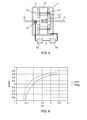
- Figure 6 of the present application shows a graph is which the power split characteristic for a drive system with input split in a conventional drive system for a hybrid vehicle, e.g. as disclosed in US 5 991 683 , is compared to a drive system according to the invention that comprises an electric variable transmission (E.V.T.).
- transmission ratio TR output torque /input torque
- W/win electric split power / input shaft power
- the system as disclosed in US'683 and E.V.T. have a similar characteristic, but points of zero mechanical split power are at different locations.
- the points of zero electrical split power may be moved relative to each other.
- the characteristic as shown in figure 7 may be achieved.
- the required split power for a given ratio range is significantly reduced.
- the transmission ratio is denoted on the horizontal axis, while the power split ratio is denoted on the vertical axis.
- the input shaft of the electric variable transmission is speed controlled. This controls the input shaft speed of the transmission, which is generally connected to an engine.
- the output is torque controlled.
- many options are possible, such as regenerative breaking, engine start en stop, boost charge etc.
Abstract
The invention also relates to a hybrid vehicle, a method for transmission of power in a drive system and to the use of a dual air gap electric machine in a drive path of a drive system with a power split device.
Description
- The invention relates to a drive system, in particular to a drive system for a hybrid vehicle, provided with an engine and an electric machine. The engine and the electric machine are power sources that each have different characteristics and of which the driving power is used to run the vehicle in a combination that is optimal for the conditions.
- In recent years hybrid vehicles have been developed and put into practical use. In such a hybrid vehicle, strengths of each power source are used to compensate for weaknesses of the other power source by using the driving power from the two types of power sources in a combination that is optimal for the driving conditions. As a result, the power performance of the vehicle is sufficiently ensured and the fuel consumption rate and emission performance are largely improved.
- Various proposals have been made for the drive systems to be used in hybrid vehicles. One proposal includes the use of a combustion engine of which the output shaft is coupled to a power split device, e.g. a planetary gear that splits the torque of the engine into two drive paths. A first path includes a mechanical path that transmits mechanical power only. A second path includes two electric machines. Between these electrical machines, this path transmits electrical power only. The two drive paths are mechanically coupled downstream of the electrical machines, e.g. using a mechanical reduction device. The coupled paths go to the final drive.A first one of the electric machines functions as a generator, and a second one of the electric machines functions as a motor or vice versa. The motor and the generator are coupled via inverters. The inverter are coupled to the battery.
- Presently, an impediment to extensive market penetration is the relatively high costs of such hybrid drive systems, forming an investment barrier and reduced margins for the manufacturer. Two major costs components in such a hybrid system are the electric machines, especially the inverter component and the battery component. In particular, if the electrical power transmitted trough the second path is high, relatively large inverters are necessary, and high stresses are placed on the cooling system for the electric parts. In practice, to keep costs down, the transmission ratio range is limited, restricting vehicle performance at low vehicles speed. In particular, low speed drive torque is negatively affected, which limits trailer tow ability.
- The invention aims to lessen the above disadvantages. Thereto, the invention provides for a drive system, in particular for a hybrid vehicle, comprising a power split device with associated drive paths, wherein at least one of the drive paths comprises two mechanically coupled electric machines that form a cascaded power split having both a mechanical and an electrical drive path.
- By using mechanically coupled, preferably mechanically integrated, electric machines forming a cascaded power split, significant cost reduction on the electric machine side can be achieved. In particular, because the coupled electric machines form a cascaded power split, a mechanical drive path is available to transmit power within the drive path with the electrical machines. This way, installed electric power and inverter rating can be significantly reduced. Further, due to integration of the electric machines, system mass, volume and complexity can be reduced.
- By using a dual air gap machine as mechanically coupled electric machines, a compact yet relatively simple mechanically integrated design can be used. Preferably, the dual air gap machine comprises a rotor, an interrotor and a stator that together form two mechanically integrated electric machines. Examples of such machines are disclosed in
US5917248 ,WO 0034066 EP1154551A2 ,WO03051660 - Advantageously, the two electric machines are also magnetically coupled, and are preferably part of an electric variable transmission such as for example disclosed by applicant in
WO 03/075437 - The power split device in the drive system can be an input split type, an output split type, a compound split type or combinations of the above.Preferably, the power split device is an output split device that is arranged to combine two power paths at the transmission output. Another option is the input split type, wherein the power split occurs at the input side of the transmission. Yet another option is the compound split configuration, where the power is split at the transmission input and again combined by a second power split device at the transmission output. The power split device may comprise a planetary gear, but may also comprise a hydraulic torque converter of suitable configuration.
- The invention also relates to a hybrid vehicle, comprising a drive system in any of the variants described above, as well as to the use of a dual air gap electric machine, in particular an electric variable transmission, in a drive path of a drive system with a power split device. The invention further relates to a method for transmission of power in a drive system, wherein the drive power is split into drive paths, and wherein the power in one of the drive paths is split again using two mechanically coupled, in particular mechanically integrated, and preferably also electromagnetically coupled electric machines. This way, the split path can be subdivided into both an electric and a mechanical drive path, thereby reducing the power requirements for the components in the electric drive path.
- Other features and aspects of the invention will be apparent from the following example, which is given as a non-limiting preferred embodiment only. In the drawings,
-
Fig. 1 shows a block diagram of a drive system incorporating an electric variable transmission; -
Fig. 2 shows a block diagram of the transmission ofFig. 1 represented as a cascaded power split; -
Fig. 3 shows a block diagram of another embodiment of a drive system incorporating an electric variable transmission; -
Fig. 4 shows a block diagram of the transmission ofFig. 5 represented as a cascaded power split; -
Fig. 5 shows a schematic representation of an electric variable transmission; -
Fig. 6 shows a graph comparing power split characteristics; -
Fig. 7 shows a graph denoting power split ratio versus transmission ratio for a drive system including an electric variable transmission; -
Fig. 8 shows a table comparing machine torques for different drive systems. - The drawings are only schematic representations of preferred, exemplary embodiments of the invention. Further, it is noted that similar or corresponding parts are denoted using the same reference numerals.
-
Fig. 1 shows adrive system 1 for a hybrid vehicle. The hybrid vehicle may e.g. be an automobile that combines two motive power sources, such as an internal combustion engine and an electric motor. Thedrive system 1 comprises apower split device 2. In this embodiment, the power split device is embodied as a planetary gear system. - The
power split device 2 is here embodied as an input split device that is arranged to split inut power. In such an input split configuration, the transmission paths are split at the transmission entrance and are coupled at the transmission output. - The input power for the
power split device 2 here is generated by acombustion engine 3. Such a combustion engine may e.g. be an internal combustion engine, such as a Diesel motor or an Otto motor. Thepower split device 2 splits the torque generated by the engine into two drive paths that meet each other at ajunction point 16 before adifferential 17. [. A first path I that is shown in the top of the drawing transmits mechanical power only. A second path II, which is shown below the first path in the drawings, comprises two integrated, mechanically and preferably also magnetically coupledelectric machines 4. Theelectric machines 4 form a cascaded power split having both a mechanical and an electrical drive path. This is illustrated infig. 2 . The second path II includes a mechanical sub path IIa and an electrical sub path IIb in parallel. - In this example, two mechanically and magnetically coupled electrical machines are provided that are part of an electric variable transmission (E.V.T.). Such an electric variable transmission is described in detail in
WO 03/075437 fig. 5 , such an electric variable transmission comprises an electromechanical converter, provided with aprimary shaft 5 having arotor 8 mounted thereon, asecondary shaft 7 having an interrotor 15 mounted thereon, and astator 10 fixedly mounted to thehousing 3 of the electromechanical converter. Viewed from theprimary shaft 5 in radial direction, therotor 8, theinterrotor 15 and thestator 10 are arranged concentrically relative to each other. Therotor 8 and thestator 10 may be designed with one or more mono- or polyphase electrically accessible windings. The interrotor 15 forms one whole both mechanically and electromagnetically, and is arranged as a conductor for the magnetic flux in tangential and radial direction. The pattern of magnetic poles in the magnetic flux conducting material on at least one side of the interrotor is free, and can be varied during operation. For more details on the electric variable transmission reference is made toWO 03/075437 fig. 3 of WO'437. - The
primary shaft 5 may for example be coupled to splitdevice 2, e.g. via a gear transmission having a fixed ratio. Thesecondary shaft 7 may for example be coupled to a drive shaft forming the mechanical path I atjunction point 16, e.g. via agear transmission 10 having a fixed ratio. -
Fig. 3 shows an alternative embodiment of the drive system 1', in which the power split device 2' is embodied as an output split device that is arranged to split output power. In this embodiment, the transmission paths I' and II' are joined at the transmission entrance via a junction point 16', and are split at the transmission output via apower split device 2 at the transmission output. Infig. 4 it is illustrated that also in this embodiment, the electric machines 4' form a cascaded power split having both a mechanical and a electrical drive path. The second path II' includes a mechanical sub path IIa' and an electrical sub path IIb' in parallel. -
Figure 6 of the present application shows a graph is which the power split characteristic for a drive system with input split in a conventional drive system for a hybrid vehicle, e.g. as disclosed inUS 5 991 683transmission ratio figure 7 may be achieved. As can be readily seen from the figure, the required split power for a given ratio range is significantly reduced. In the graph offigure 7 , the transmission ratio is denoted on the horizontal axis, while the power split ratio is denoted on the vertical axis. - In the table of
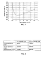
figure 8 , an overview for machine torques is given that is needed for equivalent performance to a conventional hybrid transmission The table shows the required "air gap torques" for the inner and outer airgap for an E.V.T. configuration, and the torques required for each electric machine a system of the type of US'683. In both cases the transmission input torque and the transmission output torque are the same. With electric machines of a given type and characteristic, the torque rating is proportional to machine physical size. The E.V.T. in cascade powersplit has reduced requirements for the volume of the electric machines compared with the system of US'683, as can be seen by the total installed torque figure. This leads to a much more compact package. The transmission may be controlled by controlling the electric variable transmission. In general use, the input shaft of the electric variable transmission is speed controlled. This controls the input shaft speed of the transmission, which is generally connected to an engine. The output is torque controlled. In the control of the electric variable transmission, many options are possible, such as regenerative breaking, engine start en stop, boost charge etc. - It shall be clear to the skilled person that the invention is not limited to the embodiments described herein. Many variations are possible within the scope of the invention as defined in the appended claims.
Claims (14)
- Drive system, in particular for a hybrid vehicle, comprising a power split device with associated drive paths, wherein at least one of the drive paths comprises two mechanically coupled electric machines that form a cascaded power split having both a mechanical and an electrical drive path.
- Drive system according to claim 1, wherein the mechanically coupled electric machines comprise a dual air gap machine.
- Drive system according to claim 2, wherein the dual air gap machine comprises a rotor, an interrotor and a stator that together form two mechanically integrated electric machines.
- Drive system according to any of claims 1-3, wherein the two electric machines are magnetically coupled.
- Drive system according to claim 4, wherein the two electrically and magnetically coupled electric machines are part of an electric variable transmission.
- Drive system according to claim 5, wherein the electric variable transmission comprises an electromechanical converter provided with a primary shaft having a rotor mounted thereon, a secondary shaft having an interrotor mounted thereon, and a stator, fixedly mounted to the housing of the electromechanical converter, wherein, viewed from the primary shaft (5) in radial direction, the rotor, the interrotor and the stator are arranged concentrically relative to each other, and wherein the rotor and the stator are designed with one or more mono- or polyphase, electrically accessible windings, wherein the interrotor forms one whole both mechanically and electromagnetically, and is arranged as a conductor for the magnetic flux in tangential and radial direction, and wherein the pattern of magnetic poles in the magnetic flux conducting material on at least one side of the interrotor is free and can be varied during operation.
- Drive system according to any of the preceding claims, wherein the power split device comprises a planetary gear.
- Drive system according to any of the preceding claims, wherein the power split device is an output split device that is arranged to split output power.
- Drive system according to any of the preceding claims, wherein the input power is generated is by a combustion engine.
- Drive system according to any of the preceding claims, wherein a further drive path associated with the power split device is a mechanical drive path that transmits mechanical power only.
- Drive system according any of the preceding claims, wherein said drive path comprising the two mechanically coupled electric machines includes a mechanical transmission, preferably a gear transmission having a fixed transmission ratio, at the input and/or output of the magnetically coupled electric machines.
- Hybrid vehicle, comprising a drive system according to any of the preceding claims.
- Method for transmission of power in a drive system, wherein the drive power is split into drive paths, and wherein the power in one of the drive paths is split again using two mechanically coupled electric machines, in particular dual air gap electric machines.
- Use of a dual air gap electric machine, in particular an electric variable transmission, in a drive path of a drive system with a power split device.
Priority Applications (5)
| Application Number | Priority Date | Filing Date | Title |
|---|---|---|---|
| EP07076100A EP2072311A1 (en) | 2007-12-18 | 2007-12-18 | Drive system for hybrid vehicle |
| EP08862864A EP2237982B1 (en) | 2007-12-18 | 2008-12-17 | Drive system for a hybrid vehicle |
| PCT/NL2008/050809 WO2009078715A1 (en) | 2007-12-18 | 2008-12-17 | Drive system for a hybrid vehicle |
| CN200880121421.2A CN101903199B (en) | 2007-12-18 | 2008-12-17 | Drive system for hybrid vehicle |
| US12/808,709 US20110172043A1 (en) | 2007-12-18 | 2008-12-17 | Drive system for a hybrid vehicle |
Applications Claiming Priority (1)
| Application Number | Priority Date | Filing Date | Title |
|---|---|---|---|
| EP07076100A EP2072311A1 (en) | 2007-12-18 | 2007-12-18 | Drive system for hybrid vehicle |
Publications (1)
| Publication Number | Publication Date |
|---|---|
| EP2072311A1 true EP2072311A1 (en) | 2009-06-24 |
Family
ID=39433078
Family Applications (2)
| Application Number | Title | Priority Date | Filing Date |
|---|---|---|---|
| EP07076100A Withdrawn EP2072311A1 (en) | 2007-12-18 | 2007-12-18 | Drive system for hybrid vehicle |
| EP08862864A Not-in-force EP2237982B1 (en) | 2007-12-18 | 2008-12-17 | Drive system for a hybrid vehicle |
Family Applications After (1)
| Application Number | Title | Priority Date | Filing Date |
|---|---|---|---|
| EP08862864A Not-in-force EP2237982B1 (en) | 2007-12-18 | 2008-12-17 | Drive system for a hybrid vehicle |
Country Status (4)
| Country | Link |
|---|---|
| US (1) | US20110172043A1 (en) |
| EP (2) | EP2072311A1 (en) |
| CN (1) | CN101903199B (en) |
| WO (1) | WO2009078715A1 (en) |
Cited By (2)
| Publication number | Priority date | Publication date | Assignee | Title |
|---|---|---|---|---|
| KR101509678B1 (en) * | 2009-11-23 | 2015-04-08 | 현대자동차 주식회사 | Torque split type automatic transmission |
| KR101509677B1 (en) | 2009-11-23 | 2015-04-08 | 현대자동차 주식회사 | Torque split type automatic transmission |
Families Citing this family (1)
| Publication number | Priority date | Publication date | Assignee | Title |
|---|---|---|---|---|
| DE102011005531B4 (en) * | 2011-03-15 | 2023-12-14 | Zf Friedrichshafen Ag | Hybrid drive of a motor vehicle |
Citations (10)
| Publication number | Priority date | Publication date | Assignee | Title |
|---|---|---|---|---|
| US5917248A (en) | 1995-01-31 | 1999-06-29 | Denso Corporation | System and method for driving electric vehicle |
| US5991683A (en) | 1997-03-24 | 1999-11-23 | Toyota Jidosha Kabushiki Kaisha | Power output apparatus and method of controlling the same |
| WO2000034066A1 (en) | 1998-12-08 | 2000-06-15 | Abb Ab | A hybrid drive device and a wheeled vehicle provided with a hybrid drive device |
| EP1154551A2 (en) | 2000-01-21 | 2001-11-14 | Günther Tillmann Rodenhuis | Dynamoelectric gear |
| US6405818B1 (en) * | 2000-04-11 | 2002-06-18 | Ford Global Technologies, Inc. | Hybrid electric vehicle with limited operation strategy |
| WO2003051660A2 (en) | 2001-12-14 | 2003-06-26 | C.R.F. Societa' Consortile Per Azioni | A transmission system with a continuously variable transmission ratio |
| WO2003075437A1 (en) | 2002-03-01 | 2003-09-12 | Nederlandse Organisatie Voor Toegepast- Natuurwetenschappelijk Onderzoek Tno | Electromechanical converter |
| US20040043856A1 (en) * | 2001-10-22 | 2004-03-04 | Ai Xiaolan | Electro-mechnical infinitely variable transmission |
| US20040198551A1 (en) * | 2003-04-03 | 2004-10-07 | Nissan Motor Co., Ltd. | Shift control apparatus and method for hybrid transmission applicable to hybrid vehicle |
| EP1746714A1 (en) * | 2005-07-22 | 2007-01-24 | Siemens Aktiengesellschaft | Electric transmission and method for its operation |
Family Cites Families (10)
| Publication number | Priority date | Publication date | Assignee | Title |
|---|---|---|---|---|
| JP2761926B2 (en) * | 1989-07-05 | 1998-06-04 | 株式会社福原精機製作所 | Yarn feed switching device in circular knitting machine |
| JP2000350309A (en) * | 1999-06-04 | 2000-12-15 | Denso Corp | Power converting system and driving system in vehicle |
| AT408210B (en) * | 2000-01-28 | 2001-09-25 | Wachauer Oskar | ELECTRIC DRIVE FOR A VEHICLE |
| SE517681C2 (en) * | 2000-08-30 | 2002-07-02 | Abb Ab | Hybrid drive |
| JP4069901B2 (en) * | 2004-05-20 | 2008-04-02 | トヨタ自動車株式会社 | Hybrid vehicle drivetrain |
| JP4026622B2 (en) * | 2004-07-06 | 2007-12-26 | 日産自動車株式会社 | Control device for hybrid vehicle |
| DE102005046531A1 (en) * | 2005-09-28 | 2007-03-29 | Volkswagen Ag | Stepless transmission for motor vehicle, has variator formed as electromagnetic transmission with drive and output rotors that are rotatable supported and temporarily connected with input and output shafts, respectively, and stator |
| US7572201B2 (en) * | 2005-10-20 | 2009-08-11 | Ford Global Technologies, Llc | Electric hybrid powertrain system |
| US7591748B2 (en) * | 2006-08-29 | 2009-09-22 | Gm Global Technology Operations, Inc. | Electrically variable transmission with a compound motor/generator |
| EP2072312A1 (en) * | 2007-12-18 | 2009-06-24 | Nederlandse Organisatie voor toegepast- natuurwetenschappelijk onderzoek TNO | A vehicle drive system and use of an electromechanical converter |
-
2007
- 2007-12-18 EP EP07076100A patent/EP2072311A1/en not_active Withdrawn
-
2008
- 2008-12-17 CN CN200880121421.2A patent/CN101903199B/en not_active Expired - Fee Related
- 2008-12-17 WO PCT/NL2008/050809 patent/WO2009078715A1/en active Application Filing
- 2008-12-17 EP EP08862864A patent/EP2237982B1/en not_active Not-in-force
- 2008-12-17 US US12/808,709 patent/US20110172043A1/en not_active Abandoned
Patent Citations (10)
| Publication number | Priority date | Publication date | Assignee | Title |
|---|---|---|---|---|
| US5917248A (en) | 1995-01-31 | 1999-06-29 | Denso Corporation | System and method for driving electric vehicle |
| US5991683A (en) | 1997-03-24 | 1999-11-23 | Toyota Jidosha Kabushiki Kaisha | Power output apparatus and method of controlling the same |
| WO2000034066A1 (en) | 1998-12-08 | 2000-06-15 | Abb Ab | A hybrid drive device and a wheeled vehicle provided with a hybrid drive device |
| EP1154551A2 (en) | 2000-01-21 | 2001-11-14 | Günther Tillmann Rodenhuis | Dynamoelectric gear |
| US6405818B1 (en) * | 2000-04-11 | 2002-06-18 | Ford Global Technologies, Inc. | Hybrid electric vehicle with limited operation strategy |
| US20040043856A1 (en) * | 2001-10-22 | 2004-03-04 | Ai Xiaolan | Electro-mechnical infinitely variable transmission |
| WO2003051660A2 (en) | 2001-12-14 | 2003-06-26 | C.R.F. Societa' Consortile Per Azioni | A transmission system with a continuously variable transmission ratio |
| WO2003075437A1 (en) | 2002-03-01 | 2003-09-12 | Nederlandse Organisatie Voor Toegepast- Natuurwetenschappelijk Onderzoek Tno | Electromechanical converter |
| US20040198551A1 (en) * | 2003-04-03 | 2004-10-07 | Nissan Motor Co., Ltd. | Shift control apparatus and method for hybrid transmission applicable to hybrid vehicle |
| EP1746714A1 (en) * | 2005-07-22 | 2007-01-24 | Siemens Aktiengesellschaft | Electric transmission and method for its operation |
Non-Patent Citations (1)
| Title |
|---|
| LONGYA XU: "A new breed of electric machines- basic analysis and applications of dual mechanical port electric machines", PROC. 8TH INT. CONF. ELECTRICAL MACHINES AND SYSTEMS, 2005, pages 24 - 29 |
Cited By (2)
| Publication number | Priority date | Publication date | Assignee | Title |
|---|---|---|---|---|
| KR101509678B1 (en) * | 2009-11-23 | 2015-04-08 | 현대자동차 주식회사 | Torque split type automatic transmission |
| KR101509677B1 (en) | 2009-11-23 | 2015-04-08 | 현대자동차 주식회사 | Torque split type automatic transmission |
Also Published As
| Publication number | Publication date |
|---|---|
| WO2009078715A1 (en) | 2009-06-25 |
| CN101903199B (en) | 2014-02-12 |
| US20110172043A1 (en) | 2011-07-14 |
| CN101903199A (en) | 2010-12-01 |
| EP2237982B1 (en) | 2012-11-07 |
| EP2237982A1 (en) | 2010-10-13 |
Similar Documents
| Publication | Publication Date | Title |
|---|---|---|
| CA2471811C (en) | Drive apparatus for hybrid vehicle | |
| US6251037B1 (en) | Hybrid drive for vehicles and the like | |
| JP3949966B2 (en) | Power combination device for hybrid electric vehicle | |
| US8197373B2 (en) | Power unit | |
| EP1085644B1 (en) | Hybrid car and dynamo-electric machine | |
| US20170063187A1 (en) | Electric machine for hybrid powertrain with engine belt drive | |
| US6817432B2 (en) | Hybrid vehicle | |
| CA2704804A1 (en) | Hybrid-vehicle drive system with a transmission | |
| US20090250275A1 (en) | Drive device for hybrid vehicle | |
| WO2008075130A1 (en) | Power unit for an automotive vehicle and vehicle including such a power unit | |
| US20130119900A1 (en) | Motor torque ripple compensation | |
| AU2002361394A1 (en) | A transmission system with a continuously variable transmission ratio | |
| EP2237982B1 (en) | Drive system for a hybrid vehicle | |
| US9915198B2 (en) | Belt pulley arrangement for a belt drive for driving auxiliary units of a motor vehicle and method for driving an auxiliary unit of a motor vehicle connected via a belt pulley arrangement | |
| US20120133227A1 (en) | Motor drive system arrangement to reduce torque ripple | |
| EP2578428B1 (en) | Flexible parallel and serial hybrid device | |
| JP3752487B2 (en) | Hybrid vehicle and rotating electric machine | |
| KR101573093B1 (en) | A vehicle drive system and use of an electromechanical converter | |
| JP4548388B2 (en) | Hybrid vehicle, control device and control method thereof | |
| US20070080589A1 (en) | Consolidated energy system generator | |
| CN101909913A (en) | An accessory drive system and use of an electromechanical converter | |
| JP4196545B2 (en) | Power output apparatus and electric vehicle equipped with the same | |
| KR20190067467A (en) | Drive system of hybrid electric vehicle | |
| CN110870179B (en) | Vehicle propulsion system | |
| CA2548815A1 (en) | Hybrid-vehicle drive system and operation method with a transmission |
Legal Events
| Date | Code | Title | Description |
|---|---|---|---|
| PUAI | Public reference made under article 153(3) epc to a published international application that has entered the european phase |
Free format text: ORIGINAL CODE: 0009012 |
|
| AK | Designated contracting states |
Kind code of ref document: A1 Designated state(s): AT BE BG CH CY CZ DE DK EE ES FI FR GB GR HU IE IS IT LI LT LU LV MC MT NL PL PT RO SE SI SK TR |
|
| AX | Request for extension of the european patent |
Extension state: AL BA HR MK RS |
|
| 17P | Request for examination filed |
Effective date: 20091228 |
|
| 17Q | First examination report despatched |
Effective date: 20100125 |
|
| AKX | Designation fees paid |
Designated state(s): AT BE BG CH CY CZ DE DK EE ES FI FR GB GR HU IE IS IT LI LT LU LV MC MT NL PL PT RO SE SI SK TR |
|
| D17P | Request for examination filed (deleted) | ||
| REG | Reference to a national code |
Ref country code: DE Ref legal event code: 8566 |
|
| STAA | Information on the status of an ep patent application or granted ep patent |
Free format text: STATUS: THE APPLICATION IS DEEMED TO BE WITHDRAWN |
|
| 18D | Application deemed to be withdrawn |
Effective date: 20091229 |