EP2071998B1 - Einrichtung zum manuellen Waschen von Böden oder von flachen Oberflächen allgemein - Google Patents
Einrichtung zum manuellen Waschen von Böden oder von flachen Oberflächen allgemein Download PDFInfo
- Publication number
- EP2071998B1 EP2071998B1 EP07425806A EP07425806A EP2071998B1 EP 2071998 B1 EP2071998 B1 EP 2071998B1 EP 07425806 A EP07425806 A EP 07425806A EP 07425806 A EP07425806 A EP 07425806A EP 2071998 B1 EP2071998 B1 EP 2071998B1
- Authority
- EP
- European Patent Office
- Prior art keywords
- plate
- implement
- pivoting axis
- washed
- directed toward
- Prior art date
- Legal status (The legal status is an assumption and is not a legal conclusion. Google has not performed a legal analysis and makes no representation as to the accuracy of the status listed.)
- Not-in-force
Links
- 238000005406 washing Methods 0.000 title claims abstract description 21
- 238000004140 cleaning Methods 0.000 claims abstract description 33
- 230000014759 maintenance of location Effects 0.000 claims description 4
- 230000000295 complement effect Effects 0.000 claims description 3
- 238000001035 drying Methods 0.000 description 6
- 239000007788 liquid Substances 0.000 description 4
- 230000009471 action Effects 0.000 description 3
- 238000005108 dry cleaning Methods 0.000 description 3
- 230000036961 partial effect Effects 0.000 description 3
- 230000000670 limiting effect Effects 0.000 description 2
- 239000000463 material Substances 0.000 description 2
- 238000013459 approach Methods 0.000 description 1
- 230000002860 competitive effect Effects 0.000 description 1
- 239000003599 detergent Substances 0.000 description 1
- 238000000034 method Methods 0.000 description 1
- 230000005012 migration Effects 0.000 description 1
- 238000013508 migration Methods 0.000 description 1
- 238000012986 modification Methods 0.000 description 1
- 230000004048 modification Effects 0.000 description 1
- 238000011017 operating method Methods 0.000 description 1
- 244000052769 pathogen Species 0.000 description 1
- 230000001717 pathogenic effect Effects 0.000 description 1
- 230000008569 process Effects 0.000 description 1
- 230000000717 retained effect Effects 0.000 description 1
- 125000006850 spacer group Chemical group 0.000 description 1
- 229920002994 synthetic fiber Polymers 0.000 description 1
- 239000004758 synthetic textile Substances 0.000 description 1
- XLYOFNOQVPJJNP-UHFFFAOYSA-N water Substances O XLYOFNOQVPJJNP-UHFFFAOYSA-N 0.000 description 1
Images


Classifications
-
- A—HUMAN NECESSITIES
- A47—FURNITURE; DOMESTIC ARTICLES OR APPLIANCES; COFFEE MILLS; SPICE MILLS; SUCTION CLEANERS IN GENERAL
- A47L—DOMESTIC WASHING OR CLEANING; SUCTION CLEANERS IN GENERAL
- A47L13/00—Implements for cleaning floors, carpets, furniture, walls, or wall coverings
- A47L13/10—Scrubbing; Scouring; Cleaning; Polishing
- A47L13/20—Mops
- A47L13/24—Frames for mops; Mop heads
- A47L13/254—Plate frames
- A47L13/258—Plate frames of adjustable or foldable type
Definitions
- the present invention relates to an implement for manual washing of floors or flat surfaces in general.
- Implements for manually washing floors or surfaces in general are known.
- such implements are constituted generally by a frame composed of a plate-like element, which usually has a substantially rectangular plan shape and is adapted to support, on one of its faces designed to be directed toward the surface to be washed, a cleaning fringe, generally made of natural or synthetic textile material, and which is articulated, by means of its opposite face, to a connecting element which can be associated with a handle to be used in order to drag the plate-like element, and therefore the cleaning fringe, along the surface to be washed.
- the cleaning fringe In normal washing operations, the cleaning fringe is wet with water or with a detergent solution and is wrung adequately before it is applied to the implement and used, so as to avoid the use of excessive quantities of liquid and reduce the waiting time before the surface being washed dries. During these washing operations, the cleaning fringe is wet, wrung and reused several times.
- washing operations which require minimizing the risk of transport and migration of polluting or pathogen elements in the various regions of the environment being cleaned, appropriate operating procedures are provided. This case occurs for example in the cleaning of hospital environments or of particular industries in the food sector and in the pharmaceutical sector.
- the cleaning procedure entails that the cleaning fringe must be neither wrung nor reused; i.e., the cleaning fringe, once the washing liquid with which it is impregnated initially has been used up, must be removed from the implement and set aside to be washed and sterilized.
- the assigned operators are provided with a number of cleaning fringes, which are impregnated beforehand with the washing liquid, and in each instance a cleaning fringe is applied to the implement to be passed over the surface to be washed.
- a cleaning fringe is applied to the implement to be passed over the surface to be washed.
- the cleaning fringe is removed from the implement and replaced with another cleaning fringe impregnated beforehand.
- the cleaning fringes that have already been used are stored in an appropriately provided container to be then washed at high temperature before they can be reused.
- a cleaning implement that has the features set forth in the preamble of claim 1 is known from DE 296 05 019 U1 .
- the aim of the present invention is to solve the problems described above by providing an implement for manual washing of floors or flat surfaces in general which, when required, allows to reduce drying times significantly without forcing to pass over the washed surface again.
- an object of the invention is to provide an implement which is simple and easy to use.
- Another object of the invention is to provide an implement which is structurally simple and can be manufactured at competitive costs.
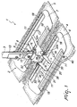
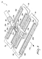
- the implement according to the invention comprises a frame 2, 2a, which is connected to a connecting element 9, 9a which can be associated with a handle 3, 3a and is composed of at least one first plate-like element 6, 6a which forms, with one of its faces designed to be directed toward the surface to be washed, a first application region for a first cleaning fringe 4, 4a.
- the frame 2, 2a comprises a second plate-like element 7, 7a, which is laterally adjacent to the first plate-like element 6, 6a and forms, with its face designed to be directed toward the surface to be washed, a second application region for a second cleaning fringe 5, 5a.
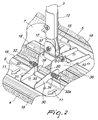
- the second plate-like element 7, 7a can move with respect to the first plate-like element 6, 6a in order to pass from an active position, in which it is substantially coplanar and laterally adjacent to the first plate-like element 6, 6a, to an inactive position, in which it is spaced from the plane of arrangement of the first plate-like element 6, 6a on the opposite side with respect to the face of the first plate-like element 6, 6a that is designed to be directed toward the surface to be washed, and vice versa.
- the two plate-like elements 6, 6a, 7, 7a have a substantially rectangular plan shape.
- the two plate-like elements 6, 6a, 7, 7a are arranged side by side at one of their longer sides, and each one forms, with its face designed to be directed toward the surface to be washed, a substantially flat application region for the corresponding cleaning fringe 4, 4a, 5, 5a.
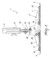
- the first plate-like element 6, 6a is hinged to the connecting element 9, 9a about a first pivoting axis 10, 10a which is parallel to the plane of arrangement of the first plate-like element 6, 6a.
- the second plate-like element 7, 7a is hinged to the first plate-like element 6, 6a about a second pivoting axis 20, 20a, which is substantially parallel to the plane of arrangement of the second plate-like element 7, 7a and is substantially perpendicular to the direction along which the two plate-like elements 6, 6a, 7, 7a are arranged side by side.
- the second pivoting axis 20, 20a is substantially parallel and spaced with respect to the first pivoting axis 10, 10a.
- the direction along which the two plate-like elements 6, 6a, 7, 7a are arranged side by side is preferably parallel to the direction in which the frame 2, 2a is dragged during use, which is indicated by the arrows 11 applied to the face of the plate-like elements 6, 6a, 7, 7a that lies opposite with respect to the one to be directed toward the surface to be washed in the first embodiment and by the arrow 11a, shown in Figure 6 , in the second embodiment.
- the second plate-like element 7, 7a can rotate about the second pivoting axis 20, 20a with respect to the first plate-like element 6, 6a in order to pass from the active position to the inactive position and vice versa.
- first plate-like element 6, 6a is connected to the second plate-like element 7, 7a by means of a central element 8, 8a, which is bridge-shaped and is fixed, with of its ends, to the second plate-like element 7, 7a and is hinged, at its opposite end, to the first plate-like element 6, 6a about the second pivoting axis 20, 20a.
- a central element 8, 8a which is bridge-shaped and is fixed, with of its ends, to the second plate-like element 7, 7a and is hinged, at its opposite end, to the first plate-like element 6, 6a about the second pivoting axis 20, 20a.
- the connecting element 9, 9a is hinged to the central element 8, 8a about the first pivoting axis 10, 10a and can be fixed, in a per se known manner, to the handle 3, 3a.
- the implement according to the invention in the two illustrated embodiments, is provided with means for retaining the second plate-like element 7, 7a in the inactive position.
- the retention means comprise friction means which are interposed between the central element 8 and the first plate-like element 6 so as to contrast by friction the rotation of the central element 8, together with the second plate-like element 7, with respect to the first plate-like element 6 about the second pivoting axis 20.
- the central element 8 is inserted, with one of its portions, between a pair of mutually parallel wings 30, 31, which are arranged on planes which are perpendicular to the second pivoting axis 20 and are fixed to the face of the first plate-like element 6 that lies opposite the face of the first plate-like element 6 that is designed to be directed toward the surface to be washed.
- the wings 30, 31 are elastically flexible toward and away from each other.
- the central element 8 is hinged to the pair of wings 30, 31 about the second pivoting axis 20 and the friction means comprise means for fastening the pair of wings 30, 31 against the portion of the central element 8 that is inserted between them.
- the fastening means comprise a bolt, which is composed of a screw 32 and a nut 33, which passes through the wings 30 and 31 and the portion of the central element 8 that is inserted between them, providing the pivoting between these elements about the second pivoting axis 20, which is formed by the axis of the screw 32.
- the fastening means comprise a pair of springs 34, 35, which are arranged around the screw 32 and are interposed respectively between the outer side of the wing 30 and the head 32a of the screw 32 and between the outer side of the wing 31 and the nut 33.
- the portion of the central element 8 that is inserted between the pair of wings 30, 31 also is constituted by a pair of wings 36, 37 which are parallel to the wings 30, 31, around the screw 32, between the springs 34, 35, it is possible to provide a spacer 38, which is positioned between the wings 36, 37 of the central element 8, so as to contrast the mutual approach of the wings 36, 37 of the central element 8 as a consequence of the thrust applied by the springs 34, 35 to the wings 30, 31.
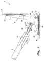
- the retention means are interposed between the central element 8a and the connecting element 9a.
- the retention means comprise engagement means which are associated with the central element 8a and can engage detachably the connecting element 9a.
- the engagement means comprise an elastically flexible wing 21a, which is connected to the central element 8a and is provided with a tooth 22a which can engage by snap action, by utilizing the elastic flexibility of the wing 21a and the rotation of the connecting element 9a about the first pivoting axis 10a with respect to the second plate-like element 7a, an abutment 23a provided on the connecting element 9a.
- the wing 21 a is further provided, proximate to the tooth 22a, with a pressing region 24a, on which it is possible to act manually in order to produce the elastic flexing of the wing 21 a so as to disengage the tooth 22a from the abutment 23a.
- the plate-like elements 6, 6a, 7, 7a are provided with means for gripping the cleaning fringes 4, 4a, 5, 5a on their face designed to be directed toward the surface to be washed.
- the grip means comprise hook-and-loop strips 40, visible only in Figure 1 , which can engage complementary hook-and-loop strips or a face which is entirely provided as a complementary hook-and-loop strip of the cleaning fringes 4, 4a, 5, 5a.
- the hook-and-loop strips 40 are supported by slats 18, 18a which are associated detachably with the plate-like elements 6, 6a, 7, 7a so as to allow their replacement in case of wear.
- the connecting element 9, 9a in both embodiments, is composed of two parts 12, 12a, 13, 13a, which are mutually pivoted about a third pivoting axis 15, 15a, which is substantially perpendicular to the first pivoting axis 10, 10a.
- the plate-like elements 6, 6a, 7, 7a are preferably arranged side by side with one of their longer sides and the central element 8, 8a connects the two plate-like elements 6, 6a, 7, 7a in a central region so as to obtain a good balancing of the implement.
- the pivoting axes 10, 10a, 20, 20a are oriented parallel to the longer sides of the plate-like elements 6, 6a, 7, 7a and therefore at right angles to the dragging direction 11, 11 a of the frame 2, 2a during its use.
- the implement according to the invention can be used both as a traditional implement for washing floors or surfaces in general and as an implement which performs simultaneously washing and at least partial drying of the treated surface.
- the second plate-like element 7, 7a When one wishes to simultaneously wash and at least partially dry a surface, the second plate-like element 7, 7a is moved to the active position, i.e., in a position in which it is coplanar to the first plate-like element 6, 6a, as shown in Figures 1 , 2 , 3 , 4 and 7 .
- a first wet fringe 4, 4a is applied to the first plate-like element 6, 6a and a second dry fringe 5, 5a is applied to the second plate-like element 7, 7a.
- Dragging the implement in the direction indicated by the arrows 11, 11a the surface is simultaneously washed by means of the action of the first fringe 4, 4a and partially dried by means of the action of the second fringe 5, 5a.
- the second plate-like element 7, 7a When one wishes to use the implement as a traditional implement, the second plate-like element 7, 7a is moved, by utilizing its ability to rotate about the second pivoting axis 20, 20a with respect to the first plate-like element 6, 6a, to the inactive position and is retained in this position by the friction between the wings 30, 31 and the portion of the central element 8, 8a that is inserted between them or by the engagement of the abutment 23a by the tooth 22a. In this manner, the second plate-like element 7, 7a is raised with respect to the first plate-like element 6, 6a and can no longer act with the second cleaning fringe 5, 5a, optionally applied thereto, on the surface to be treated, as shown in Figures 5 and 8 .
- a first fringe 4, 4a can be applied to the first plate-like element 6, 6a and can be wet or dry according to the requirements.
- the materials used, as well as the dimensions, may be any according to requirements and to the state of the art.
Landscapes
- Cleaning Implements For Floors, Carpets, Furniture, Walls, And The Like (AREA)
Claims (7)
- Gerät (1) zum manuellen Waschen von Fußböden oder ebenen Flächen im allgemeinen, mit einem Rahmen (2) bestehend aus wenigstens einem ersten plattenartigen Element (6), welches mit einer seiner Flächen, die zu der zu waschenden Bodenfläche hin gerichtet wird, einen ersten Anbringbereich für einen ersten Wischbezug (4) bildet, wobei das erste plattenartige Element (6) an einem Verbindungselement (9) schwenkbar um eine Schwenkachse (10) angeordnet ist, welche im wesentlichen parallel zur Ebene der Anordnung des ersten plattenartigen Elements (6) verläuft, wobei das Verbindungselement (9) mit einem Handgriff (3) verbunden werden kann, wobei der Rahmen (2) weiterhin ein zweites plattenartiges Element (7) aufweist, welches seitlich benachbart zum ersten plattenartigen Element (6) ist und mit seiner zur zu waschenden Bodenfläche hin gerichteten Fläche einen zweiten Anbringbereich für einen zweiten Wischbezug (5) bildet; wobei das zweite plattenartige Element (7) am ersten plattenartigen Element (6) drehbar um eine zweite Schwenkachse (20) angelenkt ist, welche im wesentlichen parallel zur Ebene der Anordnung des zweiten plattenartigen Elements (7) und im wesentlichen senkrecht zur Ausrichtung der Nebeneinander-Anordnung der beiden plattenartigen Elemente ist; wobei das zweite plattenartige Element (7) um die zweite Schwenkachse (20) relativ zu dem ersten plattenartigen Element (6) rotieren kann, um aus einer aktiven Position, in welcher es im wesentlichen koplanar mit und seitlich benachbart zu dem ersten plattenartigen Element (6) ist, in eine inaktive Position zu gelangen, in welcher es von der Ebene der Anordnung des ersten plattenartigen Elements (6) auf der entgegengesetzten Seite relativ zur Fläche des ersten plattenartigen Elements (6) beabstandet ist, die zur zu waschenden Bodenfläche hin gerichtet wird, und umgekehrt, wobei das Gerät (1) weiterhin Mittel zum Halten des zweiten plattenartigen Elements (7) in der inaktiven Position aufweist, dadurch gekennzeichnet, dass das erste plattenartige Element (6) mit dem zweiten plattenartigen Element (7) mittels eines zentralen Elements (8) verbunden ist, welches am zweiten plattenartigen Element (7) befestigt ist und am ersten plattenartigen Element (6) schwenkbar um die zweite Schwenkachse (20) angelenkt ist; wobei das Verbindungselement (9) am zentralen Element (8) schwenkbar um die erste Schwenkachse (10) angelenkt ist, welche im wesentlichen parallel und beabstandet relativ zur zweiten Schwenkachse. (20) verläuft, wobei die Schwenkachsen (10, 20) quer zur Richtung (11) orientiert sind, entlang welcher die beiden plattenartigen Elemente entlang der zu waschenden Bodenfläche gezogen werden, und dadurch, dass die Mittel zum Halten Reibungsmittel aufweisen, welche zwischen dem zentralen Element (8) und dem ersten plattenartigen Element (6) angeordnet sind, um durch Reibung der Drehung des zentralen Elements (8) zusammen mit dem zweiten plattenartigen Element (7) relativ zum ersten plattenartigen Element (6) um die zweite Schwenkachse (20) entgegenzuwirken, wobei das zentrale Element (8) mit einem seiner Teile (36, 37) zwischen einem Paar von zueinander parallelen Flügeln (30, 31) eingefügt ist, welche zueinander hin oder voneinander weg elastisch flexibel ausgebildet sind und an der Fläche des ersten plattenartigen Elements (6) befestigt sind, die gegenüber der zur zu waschenden Bodenfläche hin gerichteten Fläche liegt; wobei das zentrale Element (8) an dem Paar von Flügeln (30, 31) drehbar um die zweite Schwenkachse (20) angelenkt ist, und die Reibungsmittel Mittel zum Befestigen des Paars von Flügeln (30, 31) am Teil (36, 37) des zentralen Elements (8) aufweisen, das dazwischen angeordnet ist.
- Gerät (1) nach Anspruch 1, wobei die Befestigungsmittel eine Bolzenanordnung, welche das Schwenken des zentralen Elements (8) zu dem Paar von Flügeln (30, 31) ermöglicht, und ein Paar von Federn (34, 35) aufweisen, welche um die Schraube (32) der Bolzenanordnung und jeweils zwischen der Außenseite eines Flügels (30) und dem Kopf (32a) der Schraube der Bolzenanordnung und zwischen der Außenseite des anderen Flügels (31) und der Mutter (33) der Bolzenanordnung angeordnet sind; wobei die Mutter (33) der Bolzenanordnung entlang der Schraube (32) angezogen werden kann, um die elastische Kraft der Federn (34, 35) zu erhöhen.
- Gerät (1) nach einem oder mehreren der vorhergehenden Ansprüche, dadurch gekennzeichnet, dass die beiden plattenartigen Elemente (6, 7) mit Mitteln zum Erfassen der Wischbezüge (4, 5) auf der Fläche der beiden plattenartigen Elemente (6, 7) versehen sind, die zur zu waschenden Bodenfläche hin gerichtet wird.
- Gerät (1) nach Anspruch 3, dadurch gekennzeichnet, dass die Erfassungsmittel Klettverschluss-Streifen (40) aufweisen, welche mit komplementären Klettverschluss-Streifen auf den Wischbezügen (4, 5) zusammenwirken können.
- Gerät (1) nach einem oder mehreren der vorhergehenden Ansprüche, dadurch gekennzeichnet, dass das Verbindungselement (9) aus wenigstens zwei Teilen (12, 13) besteht, welche zueinander schwenkbar um eine dritte Schwenkachse (15) angeordnet sind, welche im wesentlichen senkrecht zur ersten Schwenkachse (10) verläuft.
- Gerät (1) nach einem oder mehreren der vorhergehenden Ansprüche, dadurch gekennzeichnet, dass die beiden plattenartigen Elemente (6, 7) im wesentlichen rechteckig sind und nebeneinander an einer ihrer beiden längeren Seiten angeordnet sind.
- Gerät (1) nach einem oder mehreren der vorhergehenden Ansprüche, dadurch gekennzeichnet, dass die erste Schwenkachse (10) und die zweite Schwenkachse (20) im wesentlichen parallel zu den längeren seiten der beiden plattenartige Elemente (6, 7) verlaufen.
Priority Applications (3)
| Application Number | Priority Date | Filing Date | Title |
|---|---|---|---|
| EP07425806A EP2071998B1 (de) | 2007-12-19 | 2007-12-19 | Einrichtung zum manuellen Waschen von Böden oder von flachen Oberflächen allgemein |
| AT07425806T ATE536128T1 (de) | 2007-12-19 | 2007-12-19 | Einrichtung zum manuellen waschen von böden oder von flachen oberflächen allgemein |
| US12/314,166 US20090158544A1 (en) | 2007-12-19 | 2008-12-05 | Implement for manual washing of floors or flat surfaces in general |
Applications Claiming Priority (1)
| Application Number | Priority Date | Filing Date | Title |
|---|---|---|---|
| EP07425806A EP2071998B1 (de) | 2007-12-19 | 2007-12-19 | Einrichtung zum manuellen Waschen von Böden oder von flachen Oberflächen allgemein |
Publications (2)
| Publication Number | Publication Date |
|---|---|
| EP2071998A1 EP2071998A1 (de) | 2009-06-24 |
| EP2071998B1 true EP2071998B1 (de) | 2011-12-07 |
Family
ID=39367577
Family Applications (1)
| Application Number | Title | Priority Date | Filing Date |
|---|---|---|---|
| EP07425806A Not-in-force EP2071998B1 (de) | 2007-12-19 | 2007-12-19 | Einrichtung zum manuellen Waschen von Böden oder von flachen Oberflächen allgemein |
Country Status (3)
| Country | Link |
|---|---|
| US (1) | US20090158544A1 (de) |
| EP (1) | EP2071998B1 (de) |
| AT (1) | ATE536128T1 (de) |
Families Citing this family (17)
| Publication number | Priority date | Publication date | Assignee | Title |
|---|---|---|---|---|
| AU2007336853B2 (en) * | 2006-12-21 | 2012-09-06 | Diversey, Inc. | Floor finish application assembly and method |
| US20120060313A1 (en) * | 2010-09-14 | 2012-03-15 | Ko Joseph Y | Cleaning cloth holding structure for mopping apparatus |
| MX337482B (es) * | 2010-11-04 | 2016-03-08 | 3M Innovative Properties Co | Trapeador. |
| ITPD20110259A1 (it) * | 2011-08-03 | 2013-02-04 | T T S S R L Tecno Trolley System | Cinematismo di blocco e di sblocco di una base per mop |
| CN202875265U (zh) * | 2012-10-11 | 2013-04-17 | 3M中国有限公司 | 可折叠旋转平板拖把和包括它的清洁工具组件 |
| USD740052S1 (en) | 2013-03-01 | 2015-10-06 | Sharkninja Operating Llc | Pad |
| USD741086S1 (en) | 2013-03-01 | 2015-10-20 | Sharkninja Operating Llc | Pad |
| USD740051S1 (en) | 2013-03-01 | 2015-10-06 | Sharkninja Operating Llc | Pad |
| USD739667S1 (en) | 2013-03-01 | 2015-09-29 | Sharkninja Operating Llc | Pad |
| USD740050S1 (en) | 2013-03-01 | 2015-10-06 | Sharkninja Operating Llc | Pad |
| US9060665B2 (en) | 2013-03-01 | 2015-06-23 | Euro-Pro Operating Llc | Floor cleaning appliance |
| USD730082S1 (en) | 2013-03-01 | 2015-05-26 | Euro-Pro Operating Llc | Pad |
| USD724349S1 (en) | 2013-03-01 | 2015-03-17 | Euro-Pro Operating Llc | Pad |
| GB2511576B (en) * | 2013-03-08 | 2015-10-14 | Vale Mill Rochdale Ltd | Mop |
| USD757618S1 (en) | 2014-07-30 | 2016-05-31 | SharkNinja Operation LLC | Pad |
| USD833097S1 (en) * | 2016-05-26 | 2018-11-06 | Sharkninja Operating Llc | Mop head |
| US11730337B2 (en) * | 2020-12-04 | 2023-08-22 | Crystal Thompson-Simpkins | Multi-purpose cleaning tool |
Family Cites Families (7)
| Publication number | Priority date | Publication date | Assignee | Title |
|---|---|---|---|---|
| DK114490D0 (da) * | 1990-05-08 | 1990-05-08 | Fr Ditlevsens Eftf A S | Mop og del til brug i forbindelse hermed |
| FR2663832A1 (fr) * | 1990-07-02 | 1992-01-03 | Amir Guy | Moyens pour la fixation amovible d'un tampon de nettoyage a la tete d'un balai. |
| DE29605019U1 (de) * | 1996-03-19 | 1996-05-23 | Fürstenberg, Friedhelm, 22111 Hamburg | Reinigungsgerät |
| JPH1043113A (ja) * | 1996-08-01 | 1998-02-17 | Kubota Corp | モップ |
| WO2006002654A1 (en) * | 2004-06-29 | 2006-01-12 | Ecolab Inc. | Mop holder for mounting a mop cover |
| CN1988837B (zh) * | 2004-07-26 | 2010-09-01 | 宝洁公司 | 清洁工具、包括清洁工具的清洁系统,以及清洁硬质表面的方法 |
| US20060085935A1 (en) * | 2004-10-27 | 2006-04-27 | White Locke Ii | Adjustable-head cleaning implement |
-
2007
- 2007-12-19 AT AT07425806T patent/ATE536128T1/de active
- 2007-12-19 EP EP07425806A patent/EP2071998B1/de not_active Not-in-force
-
2008
- 2008-12-05 US US12/314,166 patent/US20090158544A1/en not_active Abandoned
Also Published As
| Publication number | Publication date |
|---|---|
| EP2071998A1 (de) | 2009-06-24 |
| US20090158544A1 (en) | 2009-06-25 |
| ATE536128T1 (de) | 2011-12-15 |
Similar Documents
| Publication | Publication Date | Title |
|---|---|---|
| EP2071998B1 (de) | Einrichtung zum manuellen Waschen von Böden oder von flachen Oberflächen allgemein | |
| CN100593999C (zh) | 带有擦拭覆层的擦拭系统 | |
| CA1245017A (en) | Wall washing pad holder | |
| US2622256A (en) | Combined cleaning and drying implement for venetian blinds | |
| US8468644B2 (en) | Method of and apparatus for cleaning a floor | |
| CA2629118A1 (en) | Bendable dust mop | |
| CN203898229U (zh) | 可挤水的平板拖把 | |
| US20160309978A1 (en) | Device for washing floors | |
| KR102243200B1 (ko) | 다기능 밀대걸레 | |
| EP2941164B1 (de) | Verfahren zur reinigung einer oberfläche und reinigungsvorrichtung | |
| US20050039287A1 (en) | Mop head having a plurality of rectangular extensions | |
| MXPA06013804A (es) | Placa para fregar con funda de fregar. | |
| KR102177657B1 (ko) | 섬유 시트재, 섬유 시트재의 용도 및 섬유 시트재를 포함하는 청소 장치 | |
| RU2682338C1 (ru) | Текстиль для уборки, его применение и плоская швабра, включающая в себя такой текстиль для уборки | |
| WO2024208369A1 (zh) | 一种无纺布拖把 | |
| CA2600131C (en) | Surface cleaning device | |
| CN205866704U (zh) | 自拧干拖把清洁部件 | |
| CN210796915U (zh) | 一种地毯丝光机的丝光组件 | |
| US2800674A (en) | Mop cloth or element | |
| JP5912947B2 (ja) | モップ用拭体及びモップ | |
| CN216675667U (zh) | 一种拖把 | |
| US2671919A (en) | Mop holder | |
| CN207084784U (zh) | 一种挤水拖把 | |
| CN206295330U (zh) | 一种拖把头及其拖把 | |
| US20150173584A1 (en) | Mop material, a mop pad, a mop, and a method of manufacturing mop material |
Legal Events
| Date | Code | Title | Description |
|---|---|---|---|
| PUAI | Public reference made under article 153(3) epc to a published international application that has entered the european phase |
Free format text: ORIGINAL CODE: 0009012 |
|
| AK | Designated contracting states |
Kind code of ref document: A1 Designated state(s): AT BE BG CH CY CZ DE DK EE ES FI FR GB GR HU IE IS IT LI LT LU LV MC MT NL PL PT RO SE SI SK TR |
|
| AX | Request for extension of the european patent |
Extension state: AL BA HR MK RS |
|
| 17P | Request for examination filed |
Effective date: 20091119 |
|
| AKX | Designation fees paid |
Designated state(s): AT BE BG CH CY CZ DE DK EE ES FI FR GB GR HU IE IS IT LI LT LU LV MC MT NL PL PT RO SE SI SK TR |
|
| 17Q | First examination report despatched |
Effective date: 20100805 |
|
| GRAP | Despatch of communication of intention to grant a patent |
Free format text: ORIGINAL CODE: EPIDOSNIGR1 |
|
| GRAS | Grant fee paid |
Free format text: ORIGINAL CODE: EPIDOSNIGR3 |
|
| GRAA | (expected) grant |
Free format text: ORIGINAL CODE: 0009210 |
|
| AK | Designated contracting states |
Kind code of ref document: B1 Designated state(s): AT BE BG CH CY CZ DE DK EE ES FI FR GB GR HU IE IS IT LI LT LU LV MC MT NL PL PT RO SE SI SK TR |
|
| REG | Reference to a national code |
Ref country code: GB Ref legal event code: FG4D |
|
| REG | Reference to a national code |
Ref country code: CH Ref legal event code: EP |
|
| REG | Reference to a national code |
Ref country code: IE Ref legal event code: FG4D |
|
| REG | Reference to a national code |
Ref country code: DE Ref legal event code: R096 Ref document number: 602007019194 Country of ref document: DE Effective date: 20120209 |
|
| REG | Reference to a national code |
Ref country code: NL Ref legal event code: VDEP Effective date: 20111207 |
|
| PG25 | Lapsed in a contracting state [announced via postgrant information from national office to epo] |
Ref country code: LT Free format text: LAPSE BECAUSE OF FAILURE TO SUBMIT A TRANSLATION OF THE DESCRIPTION OR TO PAY THE FEE WITHIN THE PRESCRIBED TIME-LIMIT Effective date: 20111207 |
|
| LTIE | Lt: invalidation of european patent or patent extension |
Effective date: 20111207 |
|
| PG25 | Lapsed in a contracting state [announced via postgrant information from national office to epo] |
Ref country code: LV Free format text: LAPSE BECAUSE OF FAILURE TO SUBMIT A TRANSLATION OF THE DESCRIPTION OR TO PAY THE FEE WITHIN THE PRESCRIBED TIME-LIMIT Effective date: 20111207 Ref country code: SI Free format text: LAPSE BECAUSE OF FAILURE TO SUBMIT A TRANSLATION OF THE DESCRIPTION OR TO PAY THE FEE WITHIN THE PRESCRIBED TIME-LIMIT Effective date: 20111207 Ref country code: SE Free format text: LAPSE BECAUSE OF FAILURE TO SUBMIT A TRANSLATION OF THE DESCRIPTION OR TO PAY THE FEE WITHIN THE PRESCRIBED TIME-LIMIT Effective date: 20111207 Ref country code: GR Free format text: LAPSE BECAUSE OF FAILURE TO SUBMIT A TRANSLATION OF THE DESCRIPTION OR TO PAY THE FEE WITHIN THE PRESCRIBED TIME-LIMIT Effective date: 20120308 Ref country code: NL Free format text: LAPSE BECAUSE OF FAILURE TO SUBMIT A TRANSLATION OF THE DESCRIPTION OR TO PAY THE FEE WITHIN THE PRESCRIBED TIME-LIMIT Effective date: 20111207 |
|
| PG25 | Lapsed in a contracting state [announced via postgrant information from national office to epo] |
Ref country code: CY Free format text: LAPSE BECAUSE OF FAILURE TO SUBMIT A TRANSLATION OF THE DESCRIPTION OR TO PAY THE FEE WITHIN THE PRESCRIBED TIME-LIMIT Effective date: 20111207 Ref country code: BE Free format text: LAPSE BECAUSE OF FAILURE TO SUBMIT A TRANSLATION OF THE DESCRIPTION OR TO PAY THE FEE WITHIN THE PRESCRIBED TIME-LIMIT Effective date: 20111207 |
|
| PG25 | Lapsed in a contracting state [announced via postgrant information from national office to epo] |
Ref country code: CZ Free format text: LAPSE BECAUSE OF FAILURE TO SUBMIT A TRANSLATION OF THE DESCRIPTION OR TO PAY THE FEE WITHIN THE PRESCRIBED TIME-LIMIT Effective date: 20111207 Ref country code: IS Free format text: LAPSE BECAUSE OF FAILURE TO SUBMIT A TRANSLATION OF THE DESCRIPTION OR TO PAY THE FEE WITHIN THE PRESCRIBED TIME-LIMIT Effective date: 20120407 Ref country code: BG Free format text: LAPSE BECAUSE OF FAILURE TO SUBMIT A TRANSLATION OF THE DESCRIPTION OR TO PAY THE FEE WITHIN THE PRESCRIBED TIME-LIMIT Effective date: 20120307 Ref country code: EE Free format text: LAPSE BECAUSE OF FAILURE TO SUBMIT A TRANSLATION OF THE DESCRIPTION OR TO PAY THE FEE WITHIN THE PRESCRIBED TIME-LIMIT Effective date: 20111207 Ref country code: MC Free format text: LAPSE BECAUSE OF NON-PAYMENT OF DUE FEES Effective date: 20111231 Ref country code: SK Free format text: LAPSE BECAUSE OF FAILURE TO SUBMIT A TRANSLATION OF THE DESCRIPTION OR TO PAY THE FEE WITHIN THE PRESCRIBED TIME-LIMIT Effective date: 20111207 |
|
| REG | Reference to a national code |
Ref country code: CH Ref legal event code: PL |
|
| PG25 | Lapsed in a contracting state [announced via postgrant information from national office to epo] |
Ref country code: PT Free format text: LAPSE BECAUSE OF FAILURE TO SUBMIT A TRANSLATION OF THE DESCRIPTION OR TO PAY THE FEE WITHIN THE PRESCRIBED TIME-LIMIT Effective date: 20120409 Ref country code: RO Free format text: LAPSE BECAUSE OF FAILURE TO SUBMIT A TRANSLATION OF THE DESCRIPTION OR TO PAY THE FEE WITHIN THE PRESCRIBED TIME-LIMIT Effective date: 20111207 Ref country code: PL Free format text: LAPSE BECAUSE OF FAILURE TO SUBMIT A TRANSLATION OF THE DESCRIPTION OR TO PAY THE FEE WITHIN THE PRESCRIBED TIME-LIMIT Effective date: 20111207 |
|
| REG | Reference to a national code |
Ref country code: AT Ref legal event code: MK05 Ref document number: 536128 Country of ref document: AT Kind code of ref document: T Effective date: 20111207 |
|
| REG | Reference to a national code |
Ref country code: IE Ref legal event code: MM4A |
|
| PLBE | No opposition filed within time limit |
Free format text: ORIGINAL CODE: 0009261 |
|
| STAA | Information on the status of an ep patent application or granted ep patent |
Free format text: STATUS: NO OPPOSITION FILED WITHIN TIME LIMIT |
|
| PG25 | Lapsed in a contracting state [announced via postgrant information from national office to epo] |
Ref country code: CH Free format text: LAPSE BECAUSE OF NON-PAYMENT OF DUE FEES Effective date: 20111231 Ref country code: DK Free format text: LAPSE BECAUSE OF FAILURE TO SUBMIT A TRANSLATION OF THE DESCRIPTION OR TO PAY THE FEE WITHIN THE PRESCRIBED TIME-LIMIT Effective date: 20111207 Ref country code: LI Free format text: LAPSE BECAUSE OF NON-PAYMENT OF DUE FEES Effective date: 20111231 Ref country code: IE Free format text: LAPSE BECAUSE OF NON-PAYMENT OF DUE FEES Effective date: 20111219 |
|
| 26N | No opposition filed |
Effective date: 20120910 |
|
| PG25 | Lapsed in a contracting state [announced via postgrant information from national office to epo] |
Ref country code: IT Free format text: LAPSE BECAUSE OF FAILURE TO SUBMIT A TRANSLATION OF THE DESCRIPTION OR TO PAY THE FEE WITHIN THE PRESCRIBED TIME-LIMIT Effective date: 20111207 |
|
| REG | Reference to a national code |
Ref country code: DE Ref legal event code: R097 Ref document number: 602007019194 Country of ref document: DE Effective date: 20120910 |
|
| PG25 | Lapsed in a contracting state [announced via postgrant information from national office to epo] |
Ref country code: AT Free format text: LAPSE BECAUSE OF FAILURE TO SUBMIT A TRANSLATION OF THE DESCRIPTION OR TO PAY THE FEE WITHIN THE PRESCRIBED TIME-LIMIT Effective date: 20111207 |
|
| PG25 | Lapsed in a contracting state [announced via postgrant information from national office to epo] |
Ref country code: MT Free format text: LAPSE BECAUSE OF FAILURE TO SUBMIT A TRANSLATION OF THE DESCRIPTION OR TO PAY THE FEE WITHIN THE PRESCRIBED TIME-LIMIT Effective date: 20111207 |
|
| PGFP | Annual fee paid to national office [announced via postgrant information from national office to epo] |
Ref country code: GB Payment date: 20121220 Year of fee payment: 6 |
|
| PGFP | Annual fee paid to national office [announced via postgrant information from national office to epo] |
Ref country code: FR Payment date: 20121220 Year of fee payment: 6 |
|
| PG25 | Lapsed in a contracting state [announced via postgrant information from national office to epo] |
Ref country code: ES Free format text: LAPSE BECAUSE OF FAILURE TO SUBMIT A TRANSLATION OF THE DESCRIPTION OR TO PAY THE FEE WITHIN THE PRESCRIBED TIME-LIMIT Effective date: 20120318 |
|
| PGFP | Annual fee paid to national office [announced via postgrant information from national office to epo] |
Ref country code: DE Payment date: 20130130 Year of fee payment: 6 |
|
| PG25 | Lapsed in a contracting state [announced via postgrant information from national office to epo] |
Ref country code: LU Free format text: LAPSE BECAUSE OF NON-PAYMENT OF DUE FEES Effective date: 20111219 |
|
| PG25 | Lapsed in a contracting state [announced via postgrant information from national office to epo] |
Ref country code: FI Free format text: LAPSE BECAUSE OF FAILURE TO SUBMIT A TRANSLATION OF THE DESCRIPTION OR TO PAY THE FEE WITHIN THE PRESCRIBED TIME-LIMIT Effective date: 20111207 |
|
| PG25 | Lapsed in a contracting state [announced via postgrant information from national office to epo] |
Ref country code: TR Free format text: LAPSE BECAUSE OF FAILURE TO SUBMIT A TRANSLATION OF THE DESCRIPTION OR TO PAY THE FEE WITHIN THE PRESCRIBED TIME-LIMIT Effective date: 20111207 |
|
| PG25 | Lapsed in a contracting state [announced via postgrant information from national office to epo] |
Ref country code: HU Free format text: LAPSE BECAUSE OF FAILURE TO SUBMIT A TRANSLATION OF THE DESCRIPTION OR TO PAY THE FEE WITHIN THE PRESCRIBED TIME-LIMIT Effective date: 20111207 |
|
| REG | Reference to a national code |
Ref country code: DE Ref legal event code: R119 Ref document number: 602007019194 Country of ref document: DE |
|
| GBPC | Gb: european patent ceased through non-payment of renewal fee |
Effective date: 20131219 |
|
| REG | Reference to a national code |
Ref country code: FR Ref legal event code: ST Effective date: 20140829 |
|
| REG | Reference to a national code |
Ref country code: DE Ref legal event code: R119 Ref document number: 602007019194 Country of ref document: DE Effective date: 20140701 |
|
| PG25 | Lapsed in a contracting state [announced via postgrant information from national office to epo] |
Ref country code: DE Free format text: LAPSE BECAUSE OF NON-PAYMENT OF DUE FEES Effective date: 20140701 |
|
| PG25 | Lapsed in a contracting state [announced via postgrant information from national office to epo] |
Ref country code: FR Free format text: LAPSE BECAUSE OF NON-PAYMENT OF DUE FEES Effective date: 20131231 Ref country code: GB Free format text: LAPSE BECAUSE OF NON-PAYMENT OF DUE FEES Effective date: 20131219 |