EP2071981B1 - Base of a shelf with an arched front edge - Google Patents
Base of a shelf with an arched front edge Download PDFInfo
- Publication number
- EP2071981B1 EP2071981B1 EP08021053A EP08021053A EP2071981B1 EP 2071981 B1 EP2071981 B1 EP 2071981B1 EP 08021053 A EP08021053 A EP 08021053A EP 08021053 A EP08021053 A EP 08021053A EP 2071981 B1 EP2071981 B1 EP 2071981B1
- Authority
- EP
- European Patent Office
- Prior art keywords
- base
- front strip
- shelf
- base according
- strip
- Prior art date
- Legal status (The legal status is an assumption and is not a legal conclusion. Google has not performed a legal analysis and makes no representation as to the accuracy of the status listed.)
- Not-in-force
Links
Images

Classifications
-
- A—HUMAN NECESSITIES
- A47—FURNITURE; DOMESTIC ARTICLES OR APPLIANCES; COFFEE MILLS; SPICE MILLS; SUCTION CLEANERS IN GENERAL
- A47B—TABLES; DESKS; OFFICE FURNITURE; CABINETS; DRAWERS; GENERAL DETAILS OF FURNITURE
- A47B96/00—Details of cabinets, racks or shelf units not covered by a single one of groups A47B43/00 - A47B95/00; General details of furniture
- A47B96/02—Shelves
- A47B96/021—Structural features of shelf bases
-
- A—HUMAN NECESSITIES
- A47—FURNITURE; DOMESTIC ARTICLES OR APPLIANCES; COFFEE MILLS; SPICE MILLS; SUCTION CLEANERS IN GENERAL
- A47F—SPECIAL FURNITURE, FITTINGS, OR ACCESSORIES FOR SHOPS, STOREHOUSES, BARS, RESTAURANTS OR THE LIKE; PAYING COUNTERS
- A47F5/00—Show stands, hangers, or shelves characterised by their constructional features
- A47F5/0043—Show shelves
- A47F5/0068—Shelf extensions, e.g. fixed on price rail
Definitions
- the present invention relates to a bottom of a shelf with an arcuately extending end edge.
- a shelf is made, for example US 2,711,741 known.
- the invention is therefore based on the object to provide a bottom of a shelf with an arcuately extending end edge with a front strip without the front strip must be similar vorgebogen as the front edge of the floor.
- the object is achieved in that in the region of the front edge of the bottom has a downwardly sloping in the installed state of the soil level, wherein the bottom in the region of the stage has means for clip-receiving a front strip.
- this forms the top of the front bar in the clipped state on the level a level with the ground.
- both on the bar and on the floor means are required that allow such a clip operation.
- the ledge would overhang the ground.
- the floor has a corresponding step for receiving the bar.
- the step separated by slots having individual sections that is, that the step is segmented.
- the floor should be formed in the region of the front edge - as already stated - extending arcuately.
- the individual sections are separated by slots.
- the subject of the invention is the clippable recording of the front strip.
- the step on its upper side has a latching nose, wherein the front strip, which has a head part and an angle adjoining body, on the underside of the body shows a projection for engagement with the latching lug.
- the step has on its front side a downwardly projecting fold.
- the body of the strip has on its underside a tab with a claw-shaped projection for the positive detection of the fold of the step. That is, the end strip is detected both by the arranged on the top of the stage locking lug and by the fold in conjunction with the tab and the claw-shaped projection positive and positive.
- the projection on the strip is aligned in the direction of the latching lug, that extends at an angle to the underside of the body of the front strip.
- the height of the projection is in this case such that in the clipped state of the front strip on the stage - as already stated several times - actually forms the top of the front bar a plane with the bottom.
- the front panel has - as already stated - a headboard, which is angled towards the floor in the installed state down.
- a headboard which is angled towards the floor in the installed state down.
- the designated 1 floor has on its front edge designated 2 level, wherein the stage 2 has individual sections 3, which are separated from each other by slots 3a.
- a latching lug 4 is provided, wherein such latching lug 4 has an edge 4 a directed towards the bottom 1.
- Such a locking lug 4 can be produced by means of punching.
- a fold 5 is provided at the front, ie in the region of the front edge of each segment. The fold 5 extends at an angle of about 90 ° degrees to the second stage.
- the front strip 10 has a head portion 11 and a body 15.
- the head portion 11 is angled inwardly approximately V-shaped and has an end inwardly directed Umbörtelung 12.
- the body 15 of the front strip 10 has on its underside the projection 16 which in the direction of the Headboard is trimmed.
- the body of the front bar 15 has on its underside the tab 17 with the claw-shaped projection 18.
- the claw-shaped projection 18 is U-shaped in cross section and detects the fold 5 of the stage 2 of the bottom 1.
- the projection 16, however, lies in the clipped Condition on the edge 4a of the locking lug 4 on.
Landscapes
- Assembled Shelves (AREA)
- Clamps And Clips (AREA)
- Connection Of Plates (AREA)
- Handcart (AREA)
Abstract
Description
Die vorliegende Erfindung betrifft einen Boden eines Regals mit einer bogenförmig verlaufenden Stirnkante. Ein solcher Regalboden ist z.B. aus
In Warenhäusern sind üblicherweise Regale zu finden, die Böden aufweisen, die in Bezug auf ihre Stirnkante im Wesentlichen gerade verlaufend ausgebildet sind. Insbesondere im Vertrieb von höherwertigen Waren, und hier insbesondere von Parfümerieartikein, wird nun des Häufigeren verlangt, dass solche Regale "organisch" ausgebildet sein sollen. Unter dem Begriff "organisch" wird verstanden, dass die Vorderkante der Böden einen geschwungenen oder bogenförmigen Verlauf, also eine ansprechende Optik, aufweist.In department stores usually shelves are found to have bottoms, which are formed with respect to their front edge substantially straight. In particular, in the distribution of higher value goods, and in particular of perfumery, now the more common is required that such shelves should be "organic" trained. The term "organic" is understood to mean that the front edge of the bottoms has a curved or curved course, that is to say an attractive appearance.
Das bedeutet aber auch, dass der Boden über seine Länge eine unterschiedliche Tiefe besitzen kann. Gerade im Bereich von Parfümerieartikeln ist es so, dass teure Parfümerieartikel häufig unmittelbar neben preiswerteren Parfümerieartikein vertrieben werden. Der Umsatz mit preiswerten Parfümerieartikeln ist ungleich höher als der mit teuren Parfümerieartikeln. Bei einem Regal mit Böden, die über ihre Länge eine gleiche Tiefe aufweisen würde dies bedeutet, dass in Bezug auf die teuren Parfümerieartikel nur einige wenige im Regal zu finden sind, wohingegen das Regal an der entsprechenden Stelle mit preiswerteren Parfümerieartikeln vollständig gefüllt ist. Aus verkaufstechnischen Gründen ist man allerdings immer bestrebt, dem Kunden den optischen Eindruck zu vermitteln, dass das Regal mit der entsprechenden Ware vollständig gefüllt ist. Dies ist bei einem Regal, das in Bezug auf die Tiefe und über die Länge gleich ausgestaltet ist, bei teuren Parfümerieartikeln kaum möglich. Dies deshalb, weil - wie bereits ausgeführt - der Umsatz mit diesen Artikeln zu gering ist.But this also means that the soil can have a different depth over its length. Especially in the field of perfumery, it is the case that expensive perfumery items are often distributed directly alongside cheaper perfumery items. Sales of low-cost perfumery items are far higher than those of expensive perfumery items. For a shelf with shelves that would have the same depth along its length, this means that there are only a few on the shelf with respect to the expensive perfumery items, whereas the shelf at the appropriate place is completely filled with cheaper perfumery items. However, for technical reasons, one always endeavors to give the customer the visual impression that the shelf is completely filled with the corresponding product. This is hardly possible in the case of a shelf, which is the same in terms of depth and length, with expensive perfumery items. This is because - as already stated - the turnover of these articles is too low.
Bei Regalen mit geschwungenen Böden wechseln sich nun Stellen in dem Regal mit geringerer Tiefe mit solchen mit größerer Tiefe ab. An Stellen des Regalbodens, die von geringerer Tiefe geprägt sind als Nachbargebiete, lagern nunmehr die teuren Parfümerieartikel mit den geringeren Umsatzmengen und vermitteln selbst bei nur geringer Anzahl immer den optischen Eindruck, dass das Regal an dieser Stelle vollständig gefüllt ist.For shelves with curved floors now alternate places in the shelf with lesser depth with those with greater depth. In places of the shelf, which are characterized by lesser depth than neighboring areas, now store the expensive perfumery items with the lower Sales volumes and convey even with only a small number always the visual impression that the shelf is completely filled at this point.
Zur Erzeugung derartiger Regalböden ist bekannt, diese Regalböden aus den Blechtafeln, z. B. durch Laserschneiden, auszuschneiden. Bei Böden von Regalen mit gerader Stirnkante und vorderer Stirnleiste werden diese durch Kanten oder Rollprofilieren hergestellt. Dies ist insofern unproblematisch, als die Stirnkanten im Wesentlichen eben sind und auch der Boden im Bereich der Stirnkanten im Wesentlichen eben ist.To produce such shelves is known, these shelves from the metal sheets, z. B. by laser cutting, cut out. For shelf shelves with a straight front edge and front trim, these are produced by edging or roll profiling. This is unproblematic insofar as the end edges are substantially flat and also the bottom in the region of the end edges is substantially flat.
Ganz anders stellt sich die Herstellung von Böden mit geschwungener Vorderkante mit entsprechender Stirnleiste dar. Ein solcher Boden mit Stirnleiste lässt sich im Wesentlichen nur durch Tiefziehen herstellen, was die Herstellung eines teuren Werkzeugs bedingt. Mit diesem Werkzeug lässt sich dann auch nur ein Boden mit einer fest vorgegebenen bogenförmigen Stirnleiste herstellen. Jede neue Variante bedingt ein neues Werkzeug.The production of floors with a curved front edge with a corresponding front strip is quite different. Such a floor with a front strip can essentially only be produced by deep drawing, which requires the production of an expensive tool. With this tool can then produce only one floor with a fixed predetermined arcuate front strip. Every new variant requires a new tool.
Der Erfindung liegt daher die Aufgabe zu Grunde, einen Boden eines Regals mit einer bogenförmig verlaufenden Stirnkante mit einer Stirnleiste zu versehen, ohne dass die Stirnleiste ähnlich vorgebogen sein muss wie die Stirnkante des Bodens.The invention is therefore based on the object to provide a bottom of a shelf with an arcuately extending end edge with a front strip without the front strip must be similar vorgebogen as the front edge of the floor.
Die Aufgabe wird erfindungsgemäß dadurch gelöst, dass im Bereich der Stirnkante der Boden eine im Einbauzustand des Bodens nach unten abfallende Stufe aufweist, wobei der Boden im Bereich der Stufe Mittel zur clipsbaren Aufnahme einer Stirnleiste aufweist. Insbesondere bildet hierbei die Oberseite der Stirnleiste im aufgeclipsten Zustand auf die Stufe eine Ebene mit dem Boden. Durch das Aufclipsen der Leiste auf die Stufe wird eine im Prinzip form- und kraftschlüssige Verbindung erreicht, die es ermöglicht, beispielsweise mit einer Stirnleiste aus Kunststoff diese dem stirnseitigen Verlauf des Bodens anzupassen. Das heißt, die Leiste wird beim Aufclipsen "zwangsverformt". Dies deshalb, weil eine Leiste aus Kunststoff bei entsprechender Wahl des Kunststoffes die hierfür erforderliche Flexibilität aufweist. Denkbar ist allerdings auch, derartige Leisten beispielsweise aus Aluminium herzustellen und diese dann allein durch den Aufclipsvorgang derart dauerhaft zu verformen, dass diese die Form des stirnseitigen Verlaufs des Bodens dauerhaft annehmen. Hiermit ist eine hohe Varianz an bogenförmigen Verläufen von Stirnseiten von Böden möglich. Die Böden müssen lediglich durch Laserschneiden oder Stanzen mit beliebiger Bogenform hergestellt werden. Die Stirnkante wird dann durch die aufgeclipste Stirnleiste abgedeckt.The object is achieved in that in the region of the front edge of the bottom has a downwardly sloping in the installed state of the soil level, wherein the bottom in the region of the stage has means for clip-receiving a front strip. In particular, this forms the top of the front bar in the clipped state on the level a level with the ground. By clipping the bar on the stage in principle positive and non-positive connection is achieved, which makes it possible, for example, with a front strip made of plastic this adjust the frontal course of the soil. That is, the bar is "forced deformed" when clipping. This is because a plastic strip with appropriate choice of the plastic has the flexibility required for this purpose. It is also conceivable, however, to produce such strips of aluminum, for example, and then to permanently deform them solely by the clip-on process in such a way that they permanently assume the shape of the frontal profile of the bottom. This makes a high variance in arcuate progressions of front sides of soils possible. The floors must be made only by laser cutting or stamping with any arch shape. The front edge is then covered by the clip-on front strip.
Verkaufstechnisch vorteilhaft ist ebenfalls, wenn der Boden über seine gesamte Oberfläche eben ausgebildet ist. Um eine Stirnleiste unter Spannung auf einen Boden aufclipsen zu können, sind sowohl an der Leiste als auch auf dem Boden Mittel erforderlich, die einen solchen Clipsvorgang erlauben. Ohne eine solche Stufe würde infolgedessen die Leiste über den Boden überstehen. Um eben dies zu vermeiden, besitzt der Boden zur Aufnahme der Leiste eine entsprechende Stufe.Also advantageous in terms of sales technology is when the bottom is flat over its entire surface. In order to clip a front strip under tension on a floor, both on the bar and on the floor means are required that allow such a clip operation. As a result, without such a step, the ledge would overhang the ground. To avoid this, the floor has a corresponding step for receiving the bar.
Weitere vorteilhafte Merkmale der Erfindung sind den Unteransprüchen zu entnehmen.Further advantageous features of the invention can be found in the dependent claims.
Insofern ist nach einem weiteren Merkmal vorgesehen, dass die Stufe durch Schlitze getrennt einzelne Abschnitte aufweist, d. h., dass die Stufe segmentiert ist. Der Boden soll im Bereich der Stirnkante - wie bereits ausgeführt - bogenförmig verlaufend ausgebildet sein. Um nun zu erreichen, dass beim Ankanten des Bodens zur Bildung der Stufe keine Verwerfungen entstehen, ist gemäß der Lehre vorgesehen, dass die einzelnen Abschnitte durch Schlitze getrennt sind.In this respect, it is provided according to a further feature that the step separated by slots having individual sections, that is, that the step is segmented. The floor should be formed in the region of the front edge - as already stated - extending arcuately. In order to achieve that no warping occurs when the bottom is anchored to form the step, it is provided according to the teaching that the individual sections are separated by slots.
Wie bereits an anderer Stelle erläutert, ist Gegenstand der Erfindung die clipsbare Aufnahme der Stirnleiste. Hierzu weist die Stufe auf ihrer Oberseite eine Rastnase auf, wobei die Frontleiste, die ein Kopfteil und einen sich daran winklig anschließenden Körper besitzt, auf der Unterseite des Körpers ein Vorsprung zum Eingriff mit der Rastnase zeigt. Zusätzlich ist vorgesehen, dass die Stufe an ihrer Stirnseite eine nach unten ragende Abkantung aufweist. Korrespondierend hierzu besitzt der Körper der Leiste auf seiner Unterseite eine Lasche mit einem krallenförmigen Ansatz zum formschlüssigen Erfassen der Abkantung der Stufe. Das heißt, die Stirnleiste wird sowohl durch die auf der Oberseite der Stufe angeordnete Rastnase als auch durch die Abkantung in Verbindung mit der Lasche und dem krallenförmigen Ansatz kraft- und formschlüssig erfasst. Um eine sichere Clipsverbindung im Bereich der Oberseite der Stufe mit der Stirnleiste zu erreichen ist vorgesehen, dass der Vorsprung an der Leiste in Richtung auf die Rastnase ausgerichtet ist, also winklig zur Unterseite des Körpers der Stirnleiste verläuft. Die Höhe des Vorsprungs ist hierbei derart, dass im aufgeclipsten Zustand der Stirnleiste auf der Stufe - wie bereits mehrfach ausgeführt - tatsächlich die Oberseite der Stirnleiste eine Ebene mit dem Boden bildet.As already explained elsewhere, the subject of the invention is the clippable recording of the front strip. For this purpose, the step on its upper side has a latching nose, wherein the front strip, which has a head part and an angle adjoining body, on the underside of the body shows a projection for engagement with the latching lug. In addition, it is provided that the step has on its front side a downwardly projecting fold. Corresponding to this, the body of the strip has on its underside a tab with a claw-shaped projection for the positive detection of the fold of the step. That is, the end strip is detected both by the arranged on the top of the stage locking lug and by the fold in conjunction with the tab and the claw-shaped projection positive and positive. In order to achieve a secure clip connection in the region of the top of the step with the front strip, it is provided that the projection on the strip is aligned in the direction of the latching lug, that extends at an angle to the underside of the body of the front strip. The height of the projection is in this case such that in the clipped state of the front strip on the stage - as already stated several times - actually forms the top of the front bar a plane with the bottom.
Die Frontleiste besitzt - wie bereits ebenfalls ausgeführt - ein Kopfteil, das in Richtung auf den Boden zu im eingebauten Zustand nach unten abgewinkelt ist. Im Bereich der Stirnseite des Kopfteils der Stirnleiste sind Mittel vorgesehen, um Schilder o.ä. aufzunehmen.The front panel has - as already stated - a headboard, which is angled towards the floor in the installed state down. In the area of the front side of the head part of the front strip means are provided to shields o.ä. take.
Anhand der Zeichnungen wird die Erfindung beispielhaft näher erläutert.
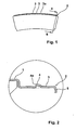
Figur 1- zeigt in einer Draufsicht einen Boden eines Regals;
Figur 2- zeigt einen Schnitt gemäß der Linie II - II aus
Figur 1 Figur 3- zeigt im Schnitt die Stirnleiste.
- FIG. 1
- shows in a plan view a bottom of a shelf;
- FIG. 2
- shows a section along the line II - II
FIG. 1 ; - FIG. 3
- shows in section the front bar.
Der mit 1 bezeichnete Boden besitzt auf seiner Vorderkante die mit 2 bezeichnete Stufe, wobei die Stufe 2 einzelne Abschnitte 3 besitzt, die untereinander durch Schlitze 3a getrennt sind.The designated 1 floor has on its front edge designated 2 level, wherein the
Aus der Schnittdarstellung gemäß
Die Stirnleiste 10 gemäß
Für den Vorgang des Aufclipsens wird nunmehr zunächst der krallenförmige Ansatz 18 der Lasche 17 in Eingriff mit der Abkantung 5 gebracht und alsdann der Vorsprung 16 hinter die Rastnase 4 zur Anlage an die Kante 4a gebracht.For the process of clipping now the claw-shaped
Claims (9)
- Base (1) of a shelf with a curvilinearly extending end edge, wherein the base (1) has, in the installed state of the base, a downwardly dropping step (2) in the region of the end edge of the base (1), wherein the base has in the region of the step a front strip (10) and means (4, 5) for clipable mounting of the front strip (10).
- Base according to claim 1, wherein the upper side of the front strip (10) in the clipped-on state on the step (2) forms a plane with the base (1).
- Base according to claim 1, characterised in that the step (2) has individual sections (3) separated by slots (3a).
- Base according to claim 1, characterised in that the step (2) has a detent nose (4) on its upper side.
- Base according to any one of the preceding claims, characterised in that the step (2) has a downwardly projecting edge fold (5) at its end face.
- Base according to any one of the preceding claims, characterised in that the front strip (10) comprises a head part (11) and a body (15) connected therewith at an angle, wherein the body (15) has on its underside a projection (16) for engagement with the detent nose (4).
- Base according to claim 6, characterised in that the body (15) has on its underside a strap (17) with a claw-shaped projection (18) for mechanical positive engagement with the edge fold (5) of the step (2).
- Base according to one of the preceding claims, 6 and 7, characterised in that the projection (16) is oriented in direction towards the detent nose (4).
- Base according to any one of the preceding claims 6 to 8, characterised in that the head part (11) of the front strip (10) has means for mounting placards or the like.
Applications Claiming Priority (1)
| Application Number | Priority Date | Filing Date | Title |
|---|---|---|---|
| DE202007017933U DE202007017933U1 (en) | 2007-12-22 | 2007-12-22 | Floor of a shelf with an arched front edge |
Publications (2)
| Publication Number | Publication Date |
|---|---|
| EP2071981A1 EP2071981A1 (en) | 2009-06-24 |
| EP2071981B1 true EP2071981B1 (en) | 2010-10-27 |
Family
ID=39155174
Family Applications (1)
| Application Number | Title | Priority Date | Filing Date |
|---|---|---|---|
| EP08021053A Not-in-force EP2071981B1 (en) | 2007-12-22 | 2008-12-04 | Base of a shelf with an arched front edge |
Country Status (3)
| Country | Link |
|---|---|
| EP (1) | EP2071981B1 (en) |
| AT (1) | ATE485744T1 (en) |
| DE (2) | DE202007017933U1 (en) |
Family Cites Families (2)
| Publication number | Priority date | Publication date | Assignee | Title |
|---|---|---|---|---|
| US2711741A (en) * | 1949-03-09 | 1955-06-28 | Georgene Parkin Wassell | Circular file |
| US5722623A (en) * | 1996-09-18 | 1998-03-03 | Burke Gibson, Inc. | Upright display assembly |
-
2007
- 2007-12-22 DE DE202007017933U patent/DE202007017933U1/en not_active Expired - Lifetime
-
2008
- 2008-12-04 AT AT08021053T patent/ATE485744T1/en active
- 2008-12-04 EP EP08021053A patent/EP2071981B1/en not_active Not-in-force
- 2008-12-04 DE DE502008001636T patent/DE502008001636D1/en active Active
Also Published As
| Publication number | Publication date |
|---|---|
| DE502008001636D1 (en) | 2010-12-09 |
| EP2071981A1 (en) | 2009-06-24 |
| ATE485744T1 (en) | 2010-11-15 |
| DE202007017933U1 (en) | 2008-03-06 |
Similar Documents
| Publication | Publication Date | Title |
|---|---|---|
| DE102005056439B4 (en) | Profile strip for use in interior fittings and kit including such a profile strip | |
| EP3496571B1 (en) | Panel for a drawer | |
| DE4016452A1 (en) | DRAWER WITH DECORATIVE PROFILE | |
| EP2389836B1 (en) | Vending shelf | |
| DE19854452B4 (en) | Joinable rails for covering, bridging and / or bordering the edges of floor and / or wall coverings | |
| EP2071981B1 (en) | Base of a shelf with an arched front edge | |
| DE202004002701U1 (en) | Profile to be integrated in paneled wall and provided with slots for joining holding elements for display of goods | |
| DE202005014929U1 (en) | Shelf tray for shelves has bent section, which exhibits V-shaped cross-section whereby front side of bent section can recoil and tray has reinforcing seam running in longitudinal direction | |
| DE10259397B4 (en) | Shelf for goods storage and presentation in retail outlets | |
| DE202010001795U1 (en) | plastic box | |
| DE202010018122U1 (en) | shelf | |
| DE10248597B4 (en) | Device for fixing facade tiles | |
| DE9316102U1 (en) | Lighting cover with price tag holder | |
| DE202011002872U1 (en) | shelf | |
| DE202004011563U1 (en) | Device for covering a front edge of a shelf base for displaying goods comprises a profile having a first vertical region, a second horizontal region connected to the first region and a third region | |
| EP0703415B1 (en) | Front panel for panel-type radiator | |
| EP3158895B1 (en) | Clip-on shelves for closets | |
| DE102004059990A1 (en) | Device for covering a front edge of a shelf base for displaying goods comprises a profile having a first vertical region, a second horizontal region connected to the first region and a third region | |
| DE202015004914U1 (en) | Erdankerplatte | |
| DE2160366A1 (en) | BRACKET FOR HOOKS, BOXES, BRACKETS, SHELVES OR DGL | |
| DE29912593U1 (en) | Front panels | |
| DE9410986U1 (en) | Shelf and presentation system | |
| DE202011100354U1 (en) | Price sign holder system | |
| DE102008063051A1 (en) | Front plate for furniture, particularly kitchen furniture, has frame formed of profiles, on which cover plate is fixed on outer side, where hollow chamber is formed on profile of frame and is opened to exterior | |
| DE202015005378U1 (en) | Formed from simple geometrical base, forward sloping canopy |
Legal Events
| Date | Code | Title | Description |
|---|---|---|---|
| PUAI | Public reference made under article 153(3) epc to a published international application that has entered the european phase |
Free format text: ORIGINAL CODE: 0009012 |
|
| 17P | Request for examination filed |
Effective date: 20090504 |
|
| AK | Designated contracting states |
Kind code of ref document: A1 Designated state(s): AT BE BG CH CY CZ DE DK EE ES FI FR GB GR HR HU IE IS IT LI LT LU LV MC MT NL NO PL PT RO SE SI SK TR |
|
| AX | Request for extension of the european patent |
Extension state: AL BA MK RS |
|
| AKX | Designation fees paid |
Designated state(s): AT BE BG CH CY CZ DE DK EE ES FI FR GB GR HR HU IE IS IT LI LT LU LV MC MT NL NO PL PT RO SE SI SK TR |
|
| GRAP | Despatch of communication of intention to grant a patent |
Free format text: ORIGINAL CODE: EPIDOSNIGR1 |
|
| GRAS | Grant fee paid |
Free format text: ORIGINAL CODE: EPIDOSNIGR3 |
|
| GRAA | (expected) grant |
Free format text: ORIGINAL CODE: 0009210 |
|
| AK | Designated contracting states |
Kind code of ref document: B1 Designated state(s): AT BE BG CH CY CZ DE DK EE ES FI FR GB GR HR HU IE IS IT LI LT LU LV MC MT NL NO PL PT RO SE SI SK TR |
|
| REG | Reference to a national code |
Ref country code: GB Ref legal event code: FG4D Free format text: NOT ENGLISH |
|
| REG | Reference to a national code |
Ref country code: CH Ref legal event code: EP |
|
| REG | Reference to a national code |
Ref country code: IE Ref legal event code: FG4D Free format text: LANGUAGE OF EP DOCUMENT: GERMAN |
|
| REF | Corresponds to: |
Ref document number: 502008001636 Country of ref document: DE Date of ref document: 20101209 Kind code of ref document: P |
|
| REG | Reference to a national code |
Ref country code: NL Ref legal event code: VDEP Effective date: 20101027 |
|
| LTIE | Lt: invalidation of european patent or patent extension |
Effective date: 20101027 |
|
| PG25 | Lapsed in a contracting state [announced via postgrant information from national office to epo] |
Ref country code: NO Free format text: LAPSE BECAUSE OF FAILURE TO SUBMIT A TRANSLATION OF THE DESCRIPTION OR TO PAY THE FEE WITHIN THE PRESCRIBED TIME-LIMIT Effective date: 20110127 Ref country code: LT Free format text: LAPSE BECAUSE OF FAILURE TO SUBMIT A TRANSLATION OF THE DESCRIPTION OR TO PAY THE FEE WITHIN THE PRESCRIBED TIME-LIMIT Effective date: 20101027 |
|
| REG | Reference to a national code |
Ref country code: IE Ref legal event code: FD4D |
|
| PG25 | Lapsed in a contracting state [announced via postgrant information from national office to epo] |
Ref country code: FI Free format text: LAPSE BECAUSE OF FAILURE TO SUBMIT A TRANSLATION OF THE DESCRIPTION OR TO PAY THE FEE WITHIN THE PRESCRIBED TIME-LIMIT Effective date: 20101027 Ref country code: LV Free format text: LAPSE BECAUSE OF FAILURE TO SUBMIT A TRANSLATION OF THE DESCRIPTION OR TO PAY THE FEE WITHIN THE PRESCRIBED TIME-LIMIT Effective date: 20101027 Ref country code: PT Free format text: LAPSE BECAUSE OF FAILURE TO SUBMIT A TRANSLATION OF THE DESCRIPTION OR TO PAY THE FEE WITHIN THE PRESCRIBED TIME-LIMIT Effective date: 20110228 Ref country code: HR Free format text: LAPSE BECAUSE OF FAILURE TO SUBMIT A TRANSLATION OF THE DESCRIPTION OR TO PAY THE FEE WITHIN THE PRESCRIBED TIME-LIMIT Effective date: 20101027 Ref country code: BG Free format text: LAPSE BECAUSE OF FAILURE TO SUBMIT A TRANSLATION OF THE DESCRIPTION OR TO PAY THE FEE WITHIN THE PRESCRIBED TIME-LIMIT Effective date: 20110127 Ref country code: IS Free format text: LAPSE BECAUSE OF FAILURE TO SUBMIT A TRANSLATION OF THE DESCRIPTION OR TO PAY THE FEE WITHIN THE PRESCRIBED TIME-LIMIT Effective date: 20110227 Ref country code: NL Free format text: LAPSE BECAUSE OF FAILURE TO SUBMIT A TRANSLATION OF THE DESCRIPTION OR TO PAY THE FEE WITHIN THE PRESCRIBED TIME-LIMIT Effective date: 20101027 Ref country code: SI Free format text: LAPSE BECAUSE OF FAILURE TO SUBMIT A TRANSLATION OF THE DESCRIPTION OR TO PAY THE FEE WITHIN THE PRESCRIBED TIME-LIMIT Effective date: 20101027 Ref country code: SE Free format text: LAPSE BECAUSE OF FAILURE TO SUBMIT A TRANSLATION OF THE DESCRIPTION OR TO PAY THE FEE WITHIN THE PRESCRIBED TIME-LIMIT Effective date: 20101027 |
|
| PGFP | Annual fee paid to national office [announced via postgrant information from national office to epo] |
Ref country code: DE Payment date: 20101109 Year of fee payment: 3 |
|
| BERE | Be: lapsed |
Owner name: LINDE LADENBAU G.M.B.H. & CO. KG Effective date: 20101231 |
|
| PG25 | Lapsed in a contracting state [announced via postgrant information from national office to epo] |
Ref country code: GR Free format text: LAPSE BECAUSE OF FAILURE TO SUBMIT A TRANSLATION OF THE DESCRIPTION OR TO PAY THE FEE WITHIN THE PRESCRIBED TIME-LIMIT Effective date: 20110128 |
|
| PG25 | Lapsed in a contracting state [announced via postgrant information from national office to epo] |
Ref country code: MC Free format text: LAPSE BECAUSE OF NON-PAYMENT OF DUE FEES Effective date: 20101231 Ref country code: EE Free format text: LAPSE BECAUSE OF FAILURE TO SUBMIT A TRANSLATION OF THE DESCRIPTION OR TO PAY THE FEE WITHIN THE PRESCRIBED TIME-LIMIT Effective date: 20101027 Ref country code: ES Free format text: LAPSE BECAUSE OF FAILURE TO SUBMIT A TRANSLATION OF THE DESCRIPTION OR TO PAY THE FEE WITHIN THE PRESCRIBED TIME-LIMIT Effective date: 20110207 Ref country code: IE Free format text: LAPSE BECAUSE OF FAILURE TO SUBMIT A TRANSLATION OF THE DESCRIPTION OR TO PAY THE FEE WITHIN THE PRESCRIBED TIME-LIMIT Effective date: 20101027 |
|
| PG25 | Lapsed in a contracting state [announced via postgrant information from national office to epo] |
Ref country code: RO Free format text: LAPSE BECAUSE OF FAILURE TO SUBMIT A TRANSLATION OF THE DESCRIPTION OR TO PAY THE FEE WITHIN THE PRESCRIBED TIME-LIMIT Effective date: 20101027 Ref country code: SK Free format text: LAPSE BECAUSE OF FAILURE TO SUBMIT A TRANSLATION OF THE DESCRIPTION OR TO PAY THE FEE WITHIN THE PRESCRIBED TIME-LIMIT Effective date: 20101027 Ref country code: PL Free format text: LAPSE BECAUSE OF FAILURE TO SUBMIT A TRANSLATION OF THE DESCRIPTION OR TO PAY THE FEE WITHIN THE PRESCRIBED TIME-LIMIT Effective date: 20101027 Ref country code: DK Free format text: LAPSE BECAUSE OF FAILURE TO SUBMIT A TRANSLATION OF THE DESCRIPTION OR TO PAY THE FEE WITHIN THE PRESCRIBED TIME-LIMIT Effective date: 20101027 |
|
| PLBE | No opposition filed within time limit |
Free format text: ORIGINAL CODE: 0009261 |
|
| STAA | Information on the status of an ep patent application or granted ep patent |
Free format text: STATUS: NO OPPOSITION FILED WITHIN TIME LIMIT |
|
| PG25 | Lapsed in a contracting state [announced via postgrant information from national office to epo] |
Ref country code: BE Free format text: LAPSE BECAUSE OF NON-PAYMENT OF DUE FEES Effective date: 20101231 |
|
| 26N | No opposition filed |
Effective date: 20110728 |
|
| REG | Reference to a national code |
Ref country code: DE Ref legal event code: R097 Ref document number: 502008001636 Country of ref document: DE Effective date: 20110728 |
|
| PG25 | Lapsed in a contracting state [announced via postgrant information from national office to epo] |
Ref country code: MT Free format text: LAPSE BECAUSE OF FAILURE TO SUBMIT A TRANSLATION OF THE DESCRIPTION OR TO PAY THE FEE WITHIN THE PRESCRIBED TIME-LIMIT Effective date: 20101027 Ref country code: IT Free format text: LAPSE BECAUSE OF FAILURE TO SUBMIT A TRANSLATION OF THE DESCRIPTION OR TO PAY THE FEE WITHIN THE PRESCRIBED TIME-LIMIT Effective date: 20101027 |
|
| PGFP | Annual fee paid to national office [announced via postgrant information from national office to epo] |
Ref country code: CZ Payment date: 20111130 Year of fee payment: 4 Ref country code: FR Payment date: 20120105 Year of fee payment: 4 |
|
| PG25 | Lapsed in a contracting state [announced via postgrant information from national office to epo] |
Ref country code: CY Free format text: LAPSE BECAUSE OF FAILURE TO SUBMIT A TRANSLATION OF THE DESCRIPTION OR TO PAY THE FEE WITHIN THE PRESCRIBED TIME-LIMIT Effective date: 20101027 |
|
| PG25 | Lapsed in a contracting state [announced via postgrant information from national office to epo] |
Ref country code: LU Free format text: LAPSE BECAUSE OF NON-PAYMENT OF DUE FEES Effective date: 20101204 Ref country code: HU Free format text: LAPSE BECAUSE OF FAILURE TO SUBMIT A TRANSLATION OF THE DESCRIPTION OR TO PAY THE FEE WITHIN THE PRESCRIBED TIME-LIMIT Effective date: 20110428 |
|
| PG25 | Lapsed in a contracting state [announced via postgrant information from national office to epo] |
Ref country code: TR Free format text: LAPSE BECAUSE OF FAILURE TO SUBMIT A TRANSLATION OF THE DESCRIPTION OR TO PAY THE FEE WITHIN THE PRESCRIBED TIME-LIMIT Effective date: 20101027 |
|
| PG25 | Lapsed in a contracting state [announced via postgrant information from national office to epo] |
Ref country code: CZ Free format text: LAPSE BECAUSE OF NON-PAYMENT OF DUE FEES Effective date: 20121204 |
|
| REG | Reference to a national code |
Ref country code: CH Ref legal event code: PL |
|
| GBPC | Gb: european patent ceased through non-payment of renewal fee |
Effective date: 20121204 |
|
| REG | Reference to a national code |
Ref country code: FR Ref legal event code: ST Effective date: 20130830 |
|
| REG | Reference to a national code |
Ref country code: DE Ref legal event code: R119 Ref document number: 502008001636 Country of ref document: DE Effective date: 20130702 |
|
| PG25 | Lapsed in a contracting state [announced via postgrant information from national office to epo] |
Ref country code: DE Free format text: LAPSE BECAUSE OF NON-PAYMENT OF DUE FEES Effective date: 20130702 Ref country code: LI Free format text: LAPSE BECAUSE OF NON-PAYMENT OF DUE FEES Effective date: 20121231 Ref country code: CH Free format text: LAPSE BECAUSE OF NON-PAYMENT OF DUE FEES Effective date: 20121231 |
|
| PG25 | Lapsed in a contracting state [announced via postgrant information from national office to epo] |
Ref country code: GB Free format text: LAPSE BECAUSE OF NON-PAYMENT OF DUE FEES Effective date: 20121204 Ref country code: FR Free format text: LAPSE BECAUSE OF NON-PAYMENT OF DUE FEES Effective date: 20130102 |
|
| PGFP | Annual fee paid to national office [announced via postgrant information from national office to epo] |
Ref country code: AT Payment date: 20141222 Year of fee payment: 7 |
|
| REG | Reference to a national code |
Ref country code: AT Ref legal event code: MM01 Ref document number: 485744 Country of ref document: AT Kind code of ref document: T Effective date: 20151204 |
|
| PG25 | Lapsed in a contracting state [announced via postgrant information from national office to epo] |
Ref country code: AT Free format text: LAPSE BECAUSE OF NON-PAYMENT OF DUE FEES Effective date: 20151204 |