EP2071269B1 - Verschlussvorrichtung einer Öffnung - Google Patents
Verschlussvorrichtung einer Öffnung Download PDFInfo
- Publication number
- EP2071269B1 EP2071269B1 EP08291167.8A EP08291167A EP2071269B1 EP 2071269 B1 EP2071269 B1 EP 2071269B1 EP 08291167 A EP08291167 A EP 08291167A EP 2071269 B1 EP2071269 B1 EP 2071269B1
- Authority
- EP
- European Patent Office
- Prior art keywords
- protection device
- bellows
- gun
- slit
- embrasure
- Prior art date
- Legal status (The legal status is an assumption and is not a legal conclusion. Google has not performed a legal analysis and makes no representation as to the accuracy of the status listed.)
- Active
Links
Images



Classifications
-
- F—MECHANICAL ENGINEERING; LIGHTING; HEATING; WEAPONS; BLASTING
- F41—WEAPONS
- F41A—FUNCTIONAL FEATURES OR DETAILS COMMON TO BOTH SMALLARMS AND ORDNANCE, e.g. CANNONS; MOUNTINGS FOR SMALLARMS OR ORDNANCE
- F41A23/00—Gun mountings, e.g. on vehicles; Disposition of guns on vehicles
- F41A23/24—Turret gun mountings
-
- F—MECHANICAL ENGINEERING; LIGHTING; HEATING; WEAPONS; BLASTING
- F41—WEAPONS
- F41A—FUNCTIONAL FEATURES OR DETAILS COMMON TO BOTH SMALLARMS AND ORDNANCE, e.g. CANNONS; MOUNTINGS FOR SMALLARMS OR ORDNANCE
- F41A27/00—Gun mountings permitting traversing or elevating movement, e.g. gun carriages
- F41A27/06—Mechanical systems
- F41A27/08—Bearings, e.g. trunnions; Brakes or blocking arrangements
- F41A27/10—Bearings for supporting a pivoting gun in a wall, e.g. a turret wall
-
- F—MECHANICAL ENGINEERING; LIGHTING; HEATING; WEAPONS; BLASTING
- F41—WEAPONS
- F41H—ARMOUR; ARMOURED TURRETS; ARMOURED OR ARMED VEHICLES; MEANS OF ATTACK OR DEFENCE, e.g. CAMOUFLAGE, IN GENERAL
- F41H5/00—Armour; Armour plates
- F41H5/20—Turrets
Definitions
- the technical field of the invention is that of protection devices ensuring the closure of an embrasure of a frame.
- Such a protection device is known from the document US 3,453,929 .
- the embrasure is a substantially rectangular opening which is delimited by two lateral flanges and two end edges.
- the dimensions of the recess are chosen according to the desired deflection for the tube of the weapon.
- NBC nuclear, bacteriological or chemical point of view
- the object of the invention is to propose a protection device making it possible to solve such problems.
- the protection device according to the invention makes it possible to ensure an NBC seal, even when the relative angular displacements of the tube relative to the embrasure are important.
- the device according to the invention maintains this level of sealing during maneuvers on contaminated ground, without restriction on the movement of the weapon.
- the level of tightness is also maintained during decontamination operations in the field.
- the subject of the invention is a protection device ensuring the closure of an embrasure of a frame, an embrasure which is delimited by two lateral edges and two end edges and in which a movable member carrying a movable member moves or pivots.
- mobile wall interposed between the outside and the inside of the frame, the device comprising at least one flexible element secured to one side of an end edge of the recess and on the other side of the movable member , the movable element being a bellows, the bellows delimiting with the wall an intermediate chamber which is connected to the internal volume of the frame, which volume is pressurized by a pressurizing means.
- the flexible bellows comprises two corrugated plies secured to one another at the level of vertices of their corrugations so as to delimit transverse grooves between the two plies.
- the bellows may also comprise rods secured to its lower ply, positioned closest to the movable wall, rods disposed at the vertices of this ply which are closest to the movable wall, and flowing in guide grooves arranged on the edges of the embrasure.
- the upper layer may have a width greater than that of the lower layer, and rub on the lateral edges of the doorway during movement of the member.
- the lateral edges of the embrasure will advantageously each have a gutter disposed between the upper layer and the guide groove, gutter connected to a means for discharging the runoff water.
- the intermediate chamber may be connected to the internal volume of the frame via a pipe carrying at least one baffle preventing the passage of runoff water from the intermediate chamber to the internal volume.
- the protective device may also include means ensuring the seal between the movable member and the lateral edges of the recess, means comprising lateral wedges integral with the member and interposed between the latter and each of the lateral flanges.
- the shims may include a profile cooperating with the guide groove.
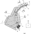
- a frame 1 which is here a turret, mounted for example on a shielded vehicle (not shown), comprises a substantially rectangular recess 2 which is delimited by two lateral flanges 2a, 2b and two end edges 2c, 2d.
- a movable member 3 (here a weapon tube) pivots in the recess 2 to allow positioning in the weapon site before firing (arrow S).
- the tube 3 is secured to a movable wall 4 which is cylindrical and which is guided on the bearing surfaces (not shown) integral with the turret 1.
- This movable wall 4 has the function of interposing between the outside and the inside of the frame
- the invention applies to any other type of frame that a turret, for example to a fixed frame such as a fort carrying a gun tube, or to a machine tool frame.
- the pivoting or movable member may be other than a weapon tube, for example a member such as a control lever or a handling means or a tool, and the movement of the member may be a pivoting or a translation compared to the frame.
- the tube 3 is connected to the wall 4 by a mask 5 which is represented on the figure 1 in a very schematic way.
- the device according to the invention comprises two flexible bellows which are not represented on the figure 1 (to allow to visualize the wall 4). Each bellows is secured to one side of an end edge 2c or 2d of the embrasure 2 and the other side of the mask 5.
- the bellows accompany the pivoting of the movable member and cover the wall 4 on either side of the mask 5 of the organ.
- the bellows 6 delimits with the wall 4 an intermediate chamber 7.
- This chamber is connected to the internal volume 10 of the turret by pipes whose inlet ports 8 (8a, 8b) are located on the figure 3 .
- the internal volume 10 of the turret 1 is pressurized by a pressurizing means 9, for example a pump connected to the outside air by means of NBC filters specific to the combat missions.
- a pressurizing means 9 for example a pump connected to the outside air by means of NBC filters specific to the combat missions.
- the pressure inside the internal volume 10 is controlled by the pressurizing means 9.
- the pressure in the intermediate chamber 7 will depend on the leakage section between the bellows 6 and the edges 2a / 2b of the embrasure and the presence of a possible dynamic pressure (wind or vehicle movement) that can be added to the pressure atmospheric.
- the mode of operation of the seal will be specified later.
- each flexible bellows 6 (6a, 6b) comprises two corrugated plies 11a, 11b which are integral with each other at vertices 12 of their corrugations.
- the upper ply 11a is the one that is in contact with the outside air and the lower ply 11b is the one that is positioned closest to the movable wall 4.
- the two layers thus delimit transverse grooves 13.
- each bellows 6 comprises rods 14 which are integral with its lower web 11b.
- the rods 14 are disposed at the vertices 15 of the lower ply 11b which are closest to the movable wall 4.
- the rods 14 circulate in guide grooves 16 which are arranged on the lateral edges 2a, 2b of the embrasure 2.
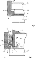
- the grooves 16 have been shown schematically on the figure 1 and they are also visible in the sectional view 4.
- the grooves 16 have a circular shape parallel to the cylindrical wall 4.
- the bellows 6 will for example be made of an elastomer such as a rubber. It will advantageously be manufactured in a single injection operation and in the form of a single piece. One could also make two separate plies 11a, 11b and then secure them, for example by gluing or heat welding.
- the rods 14 are preferably metallic and overmolded into the lower sheet 11b.
- This structure of a bellows formed of two plies increases the rigidity of the bellows 6 while facilitating a compact fold of the bellows (see the bellows 6b shown folded on the figure 2 ).
- the rods 14 constitute reinforcements that further reinforce the rigidity of the bellows 6.
- the wall 4 constitutes a stop for the median portions of the rods 14, which limits their deformation and enhances the mechanical strength of the bellows.
- a man can walk on one of the bellows without damaging it.
- the rods finally provide, thanks to the grooves 16, the guiding of the bellows 6 during the pivoting of the tube 3 of the weapon, despite the elongated shape of the recess 2 and the large deflection angle for the tube 3 (greater than 45 ° ).
- the upper ply 11a of the bellows 6 has a width which is greater than that of the lower ply 11b.
- the lateral flanges 2b (and 2a) of the recess 2 each carry a channel 17 which is disposed between the upper ply 11a and the guide groove 16.
- Each channel 17 is thus disposed facing the contact surface between the upper web 11a and the side flange 2a or 2b considered.
- the gutters are connected to a means of evacuation of the runoff water (not shown), for example a pipe which is oriented towards the outside of the turret 1.
- the figure 5 shows a cut made at the level of the mask 5.
- These means comprise two lateral shims 18 which are made integral with the member 3 (or more particularly the mask 5).
- the shims 18 are here guided by the groove 16 and simply immobilized by the bellows 6. Such an arrangement simplifies the assembly and disassembly (removal of the seal support possible without removing the mask).
- Other types of mounting shims 18 are conceivable, such as a mounting by screws.
- Each shim 18 is interposed between the mask 5 and one of the lateral flanges 2a or 2b. Here only one shim is represented.
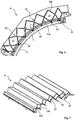
- Each shim 18 has a profile cooperating with the guide groove 16. This profile here comprises a spout 19 delimiting a notch 20 which caps the channel 17. The spout 19 is introduced into the groove 16. The figure 9 thus shows a shim 18 shown alone.
- the wedge 18 has an arcuate shape and extends over the entire width of the mask 5.
- the wedge slides on the lateral rim considered (2a or 2b). It fills the entire space between the mask 5 and the flange 2a, 2b and the spout 19 slides in the groove 16.
- the wedge 18 serves to limit the leakage sections between the mask 5 and the edges 2a / 2b of the 'embrasure.
- the nozzle 19 also ensures a cleaning of the groove 16.
- the shims 18 will be made of a material reducing friction, for example polytetrafluoroethylene (known under the trademark Teflon).
- each shim comprises a layer 18a of a cellular material (for example a closed-cell synthetic foam) or a rubber seal. This deformable layer is interposed between the shim 18 and the mask 5. It makes it possible to compensate for the dispersions of mounting dimensions and ensures the maintenance of the support of the shim 18 against the rim 2a, 2b considered.
- orifices 8 allowed to connect the intermediate chamber 7 to the internal volume 10 of the turret 1.
- the device comprises two orifices 8, an upper orifice 8a which is connected to the intermediate chamber 7 defined by the upper bellows 6a and a lower orifice 8b which is connected to the intermediate chamber 7 delimited by the lower bellows 6b.
- the figure 2 allows to visualize these tubings 21a and 21b. They are connected to one another at a distance from the orifices 8 by a connecting branch 23.
- the figure 8 shows more clearly the assembly of the tubings.
- An air intake manifold 24 is connected to the connection branch 23. This manifold opens out as can be seen on the figures 2 and 5 at a chamber 25, internal to the mask 5 and disposed laterally to the tube 3 of the weapon, chamber 25 which communicates with the volume 10 inside the turret 1.
- the various curvatures of the tubes 21, 23, 24 constitute a baffle which prevents the passage of runoff liquids (mainly water or decontamination liquids) from the intermediate chamber 7 to the internal volume 10.
- runoff liquids mainly water or decontamination liquids
- the seal is further completed by the establishment of a seal 26 which is interposed between the edges of the embrasure 2 and the wall 4 (see figures 3 and 6 ).
- This seal is of substantially rectangular overall shape. It follows the profile of the embrasure 2 and remains in contact with the wall 4 during the pivoting thereof.
- This seal makes it possible to separate the intermediate chamber 7 from the internal volume 10 at the turret 1. It prevents any passage of liquids from the intermediate chamber 7 to the internal volume 10.
- the operation of the protection device is as follows.
- the air In normal operating mode the air is in overpressure inside the internal volume 10 of the turret.
- the level of this pressure is regulated and maintained substantially constant by the pressurizing means 9.
- This pressure level is of the order of 1200 to 1600 Pa above the level of the pressure outside the turret.
- the overpressurized air passes through the tubings 24,23,21 and establishes an overpressure in the two intermediate chambers 7 (one per bellows 6).
- the air escapes through the trailing spaces separating the edges of the bellows and the lateral edges of the embrasure 2.
- the contaminated gas can not enter the intermediate chambers 7.
- these chambers are in overpressure with respect to the outside of the turret (within the limit of a headwind and a speed specified during the design).
- the air flow is therefore outgoing and it prohibits any polluted gas penetration into the intermediate chambers 7.
- the pressure in the intermediate chambers 7 equilibrates at an intermediate level between the external pressure and the pressure in the the internal volume 10. The air flow is therefore again in the outgoing direction of the intermediate chambers 7 outwardly (within the limits of headwind and speed that have been specified).
- This feature of the invention makes it possible to limit the leakage section between the internal volume 10 and the outside to the value of the sections of the ports 8a, 8b connecting the tubes (whereas the theoretical leakage section bellows 6 / embrasure 2 can to be superior).
Landscapes
- Engineering & Computer Science (AREA)
- General Engineering & Computer Science (AREA)
- Sealing Devices (AREA)
- Diaphragms And Bellows (AREA)
Claims (8)
- Schutzvorrichtung, welche das Schließen einer Schießscharte (2) eines Gestells (1) gewährleistet, wobei die Schießscharte von zwei seitlichen Rändern (2a, 2b) und zwei Endrändern (2c, 2d) begrenzt wird und in welcher sich ein mobiles Organ (3) bewegt oder dreht, welches eine bewegliche Wand (4) trägt, welche sich zwischen den äußeren Bereich und den inneren Bereich des Gestells einfügt, wobei die Vorrichtung mindestens ein flexibles Element (6) aufweist, welches einerseits mit einem Endrand der Schießscharte (2) und andererseits mit dem mobilen Organ (3) fest verbunden ist, wobei die Vorrichtung dadurch gekennzeichnet ist, dass das flexible Element ein flexibler Balg ist, wobei der Balg (6) mit der Wand (4) eine Zwischenkammer (7) abgrenzt, welche mit dem inneren Volumen (10) des Gestells (1) verbunden ist, wobei das Volumen durch ein Druckmittel (9) unter Druck gesetzt wird.
- Schutzvorrichtung nach Anspruch 1, dadurch gekennzeichnet, dass der flexible Balg (6) zwei gewellte Bahnen (11a, 11b) aufweist, welche im Bereich von Scheiteln (12) ihrer Wellenlinien derartig miteinander verbunden sind, um querverlaufende Rillen (13) zwischen den beiden Bahnen (11a, 11b) zu begrenzen.
- Schutzvorrichtung nach Anspruch 2, dadurch gekennzeichnet, dass der Balg (6) fest mit der unteren Bahn (11b), welche am dichtesten zur beweglichen Wand (4) angeordnet ist, verbundene Stangen (14) aufweist, wobei die Stangen im Bereich der Scheitel (15) dieser Bahn, welche sich am dichtesten an der beweglichen Wand (4) befinden, angeordnet sind, und sich in Führungsnuten (16) bewegen, welche an den Rändern der Schießscharte (2) eingebracht sind.
- Schutzvorrichtung nach einem der Ansprüche 2 oder 3, dadurch gekennzeichnet, dass die obere Bahn (11a) eine Breite besitzt, welche größer als diejenige der unteren Bahn (11b) ist, und bei der Verlagerung des Organs (3) an den seitlichen Rändern (2b, 2c) der Schießscharte reibt.
- Schutzvorrichtung nach einem der Ansprüche 2 oder 3, dadurch gekennzeichnet, dass die seitlichen Ränder (2a, 2b) der Schießscharte jeweils eine Rinne (17) tragen, welche zwischen der oberen Bahn (11a) und der Führungsnut (16) angeordnet ist, wobei die Rinne mit einem Mittel zum Abführen des Ablaufwassers verbunden ist.
- Schutzvorrichtung nach einem der Ansprüche 1 bis 5, dadurch gekennzeichnet, dass die Zwischenkammer (7) mit dem inneren Volumen (10) des Gestells (1) mit Hilfe eines Rohres (21a, 21b) verbunden ist, welches mindestens ein Hindernis trägt, um den Durchtritt von Ablaufwasser der Zwischenkammer (7) in das inneren Volumen (10) zu verhindern.
- Schutzvorrichtung nach einem der Ansprüche 1 bis 6, dadurch gekennzeichnet, dass sie Mittel aufweist, welche die Dichtigkeit zwischen dem mobilen Organ (2) und den seitlichen Rändern der Schießscharte gewährleisten, wobei die Mittel seitliche Einsätze (18) aufweisen, welche fest mit dem Organ (3) verbunden sind und zwischen diesem letzteren und den seitlichen Rändern (2a, 2b) jeweils eingefügt sind.
- Schutzvorrichtung nach den Ansprüchen 3 und 7, dadurch gekennzeichnet, dass die Einsätze (18) eine Profilierung (19) aufweisen, welche mit der Führungsnut (16) zusammenwirkt.
Applications Claiming Priority (1)
| Application Number | Priority Date | Filing Date | Title |
|---|---|---|---|
| FR0708566A FR2924797B1 (fr) | 2007-12-10 | 2007-12-10 | Dispositif de fermeture d'une embrasure |
Publications (3)
| Publication Number | Publication Date |
|---|---|
| EP2071269A2 EP2071269A2 (de) | 2009-06-17 |
| EP2071269A3 EP2071269A3 (de) | 2012-05-30 |
| EP2071269B1 true EP2071269B1 (de) | 2017-02-15 |
Family
ID=39708937
Family Applications (1)
| Application Number | Title | Priority Date | Filing Date |
|---|---|---|---|
| EP08291167.8A Active EP2071269B1 (de) | 2007-12-10 | 2008-12-10 | Verschlussvorrichtung einer Öffnung |
Country Status (3)
| Country | Link |
|---|---|
| US (1) | US8065948B1 (de) |
| EP (1) | EP2071269B1 (de) |
| FR (1) | FR2924797B1 (de) |
Families Citing this family (5)
| Publication number | Priority date | Publication date | Assignee | Title |
|---|---|---|---|---|
| ITTO20110455A1 (it) * | 2011-05-25 | 2012-11-26 | Oto Melara Spa | Assieme di torretta e arma a bassa riflessione radar. |
| US8438964B1 (en) * | 2011-06-05 | 2013-05-14 | Kontek Industries, Inc. | Gun ports |
| US9021965B1 (en) | 2013-04-16 | 2015-05-05 | Kontek Industries, Inc. | Laser defense gun ports |
| US9500022B1 (en) * | 2015-11-01 | 2016-11-22 | Alexey Shesvill | Slide safe apparatus and method |
| ITUB20155551A1 (it) * | 2015-11-13 | 2017-05-13 | Oto Melara Spa | Torretta con protezione per dispositivo di guida di munizioni. |
Family Cites Families (20)
| Publication number | Priority date | Publication date | Assignee | Title |
|---|---|---|---|---|
| DE59668C (de) * | GRUSON-WERK in Magdeburg - Buckau | Aus einem biegsamen Schlauch bestehende Schartendichtung für Panzer | ||
| US1276444A (en) * | 1917-05-31 | 1918-08-20 | Carroll M Taylor | Armored war-automobile. |
| US2286341A (en) * | 1938-05-31 | 1942-06-16 | Central Aircraft Corp | Airplane front gunnery means |
| GB555283A (en) * | 1939-02-18 | 1943-07-23 | Boulton Aircraft Ltd | Improved means for sealing slots in gun turrets |
| US2211491A (en) * | 1939-04-27 | 1940-08-13 | Lloyd A Brooke | Flexible port closure |
| US2573434A (en) * | 1945-03-08 | 1951-10-30 | Gen Motors Corp | Mounting for rocket launchers |
| US2457240A (en) * | 1946-09-23 | 1948-12-28 | United Shoe Machinery Corp | Shield for gun mounts |
| BE497001A (de) * | 1949-07-28 | |||
| US2897888A (en) * | 1956-05-28 | 1959-08-04 | Dragonuk Leo | Movable closure for a slot |
| US3008380A (en) * | 1959-09-30 | 1961-11-14 | Richard T Cowley | Waterproof gun cover |
| FR1485274A (fr) * | 1965-07-03 | 1967-06-16 | Rheinmetall Gmbh | Montage du berceau de canons pour tourelles blindées |
| US3453929A (en) * | 1966-08-11 | 1969-07-08 | Us Navy | Gun port shield |
| US3710681A (en) * | 1970-03-30 | 1973-01-16 | Efmc Corp | Gun mount closure or seal |
| US3742813A (en) * | 1970-12-14 | 1973-07-03 | Us Navy | Missile launcher |
| DE2128703C3 (de) * | 1971-06-09 | 1975-05-22 | Rheinstahl Ag, 4300 Essen | Geschützlager mit Blende |
| FR2371664A1 (fr) * | 1976-11-19 | 1978-06-16 | Alsetex | Dispositif lance-grenades |
| SE432669B (sv) * | 1979-10-02 | 1984-04-09 | Bofors Ab | Anordning for tetning av eldrorsoppningen i en vapenkupol |
| US4635529A (en) * | 1984-12-21 | 1987-01-13 | General Electric Company | Seal assembly |
| US4979702A (en) * | 1987-02-11 | 1990-12-25 | Franklin William L | Apparatus for opening and closing a sealed slot |
| US5756921A (en) * | 1995-12-18 | 1998-05-26 | United Defense Lp | Weapon system gun port EMI-EMP seal |
-
2007
- 2007-12-10 FR FR0708566A patent/FR2924797B1/fr not_active Expired - Fee Related
-
2008
- 2008-11-24 US US12/292,668 patent/US8065948B1/en not_active Expired - Fee Related
- 2008-12-10 EP EP08291167.8A patent/EP2071269B1/de active Active
Non-Patent Citations (1)
| Title |
|---|
| None * |
Also Published As
| Publication number | Publication date |
|---|---|
| US8065948B1 (en) | 2011-11-29 |
| FR2924797A1 (fr) | 2009-06-12 |
| EP2071269A2 (de) | 2009-06-17 |
| EP2071269A3 (de) | 2012-05-30 |
| FR2924797B1 (fr) | 2010-03-05 |
Similar Documents
| Publication | Publication Date | Title |
|---|---|---|
| EP4004427B1 (de) | Druckgasabgabevorrichtung | |
| EP2069624B1 (de) | Abnehmbare lufteinlassstruktur für eine turbostrahl-motorengondel | |
| EP2071269A2 (de) | Verschlussvorrichtung einer Öffnung | |
| FR2819221A1 (fr) | Dispositif de mise a l'air libre destine a un reservoir de vehicule automobile | |
| FR2686659A1 (fr) | Emetteur hydraulique a reservoir integre et etanche. | |
| EP2064074B1 (de) | Pannensicherer, flexibler innenschlauch | |
| EP1006299A1 (de) | Dichtungsanordnung für rotierende Wellen | |
| EP0807753B1 (de) | Schubumkehrvorrichtung eines Strahltriebwerkes mit an der Vorseite der Klappen verbundenem Wandteil | |
| EP3719374B1 (de) | Drehgelenkvorrichtung, die für die ausstattung einer anlage zur nutzung von fluiden geeignet ist, insbesondere auf einer offshore-plattform | |
| FR2501786A1 (fr) | Dispositif de roulement et de guidage d'une tuyere orientable de propulseur a reaction | |
| EP3301344B1 (de) | Anschlussvorrichtung, die eine flexible muffe zum sammeln einer flüssigkeit im falle eines lecks oder aussickerns umfasst | |
| EP3491231B1 (de) | Ansaugkrümmer mit intergrierter wärmetauscher | |
| WO2016078917A1 (fr) | Procede pour alimenter en fluide hydraulique un moteur hydraulique de roue motrice, suspension a verin s'y rapportant et vehicule ainsi equipe | |
| FR2748779A1 (fr) | Inverseur de poussee de turboreacteur a portes associees a un panneau amont | |
| EP0864740A1 (de) | Schubumkehrvorrichtung eines Turbofans mit federbelasteter Klappenaussenwand | |
| EP3574240B1 (de) | Verbinder mit flansch zur begrenzung der knickausbreitung mit einem differenzdruckventil für unterwasserflüssigkeitstransportrohr | |
| EP0748932B1 (de) | Düse mit einem Hals mit veränderlicher Geometrie | |
| EP2128425B1 (de) | Vorrichtung zur Geräuschdämpfung für eine Ansaugleitung einer Brennkraftmaschine und Ansaugleitung, die diese Vorrichtung umfasst | |
| EP0482974B1 (de) | Fahrzeug-Motorraumdichtung | |
| FR3137736A1 (fr) | Système de conduite monté entre deux éléments d’un système de distribution | |
| WO2016170268A1 (fr) | Electrovanne de purge pour dispositif d'evacuation de vapeurs | |
| FR3067438B1 (fr) | Embout de connexion d'une ligne flexible, ligne flexible et procede associes | |
| FR3113093A1 (fr) | Systeme de propulsion d’un aeronef comportant un systeme d’etancheite ameliore | |
| FR2574133A1 (fr) | Actionneur hydraulique | |
| WO2025224398A1 (fr) | Tubulure de connexion pour réservoir d'aéronef et réservoir comportant au moins une telle tubulure |
Legal Events
| Date | Code | Title | Description |
|---|---|---|---|
| PUAI | Public reference made under article 153(3) epc to a published international application that has entered the european phase |
Free format text: ORIGINAL CODE: 0009012 |
|
| AK | Designated contracting states |
Kind code of ref document: A2 Designated state(s): AT BE BG CH CY CZ DE DK EE ES FI FR GB GR HR HU IE IS IT LI LT LU LV MC MT NL NO PL PT RO SE SI SK TR |
|
| AX | Request for extension of the european patent |
Extension state: AL BA MK RS |
|
| PUAL | Search report despatched |
Free format text: ORIGINAL CODE: 0009013 |
|
| AK | Designated contracting states |
Kind code of ref document: A3 Designated state(s): AT BE BG CH CY CZ DE DK EE ES FI FR GB GR HR HU IE IS IT LI LT LU LV MC MT NL NO PL PT RO SE SI SK TR |
|
| AX | Request for extension of the european patent |
Extension state: AL BA MK RS |
|
| RIC1 | Information provided on ipc code assigned before grant |
Ipc: F41A 23/24 20060101AFI20120425BHEP Ipc: F41H 5/20 20060101ALI20120425BHEP |
|
| 17P | Request for examination filed |
Effective date: 20121123 |
|
| AKX | Designation fees paid |
Designated state(s): AT BE BG CH CY CZ DE DK EE ES FI FR GB GR HR HU IE IS IT LI LT LU LV MC MT NL NO PL PT RO SE SI SK TR |
|
| REG | Reference to a national code |
Ref country code: DE Ref legal event code: R079 Ref document number: 602008048750 Country of ref document: DE Free format text: PREVIOUS MAIN CLASS: F41A0027100000 Ipc: F41A0023240000 |
|
| GRAP | Despatch of communication of intention to grant a patent |
Free format text: ORIGINAL CODE: EPIDOSNIGR1 |
|
| RIC1 | Information provided on ipc code assigned before grant |
Ipc: F41H 5/20 20060101ALI20160630BHEP Ipc: F41A 23/24 20060101AFI20160630BHEP |
|
| INTG | Intention to grant announced |
Effective date: 20160718 |
|
| GRAJ | Information related to disapproval of communication of intention to grant by the applicant or resumption of examination proceedings by the epo deleted |
Free format text: ORIGINAL CODE: EPIDOSDIGR1 |
|
| GRAP | Despatch of communication of intention to grant a patent |
Free format text: ORIGINAL CODE: EPIDOSNIGR1 |
|
| RIN1 | Information on inventor provided before grant (corrected) |
Inventor name: BAPTISTA, DANIEL Inventor name: MASSON, MICHEL Inventor name: LEVEQUE, STEPHANE Inventor name: POIRMEUR, XAVIER |
|
| INTC | Intention to grant announced (deleted) | ||
| INTG | Intention to grant announced |
Effective date: 20161012 |
|
| GRAS | Grant fee paid |
Free format text: ORIGINAL CODE: EPIDOSNIGR3 |
|
| GRAA | (expected) grant |
Free format text: ORIGINAL CODE: 0009210 |
|
| AK | Designated contracting states |
Kind code of ref document: B1 Designated state(s): AT BE BG CH CY CZ DE DK EE ES FI FR GB GR HR HU IE IS IT LI LT LU LV MC MT NL NO PL PT RO SE SI SK TR |
|
| REG | Reference to a national code |
Ref country code: CH Ref legal event code: EP Ref country code: GB Ref legal event code: FG4D Free format text: NOT ENGLISH |
|
| REG | Reference to a national code |
Ref country code: IE Ref legal event code: FG4D Free format text: LANGUAGE OF EP DOCUMENT: FRENCH |
|
| REG | Reference to a national code |
Ref country code: AT Ref legal event code: REF Ref document number: 868154 Country of ref document: AT Kind code of ref document: T Effective date: 20170315 |
|
| REG | Reference to a national code |
Ref country code: DE Ref legal event code: R096 Ref document number: 602008048750 Country of ref document: DE |
|
| REG | Reference to a national code |
Ref country code: NO Ref legal event code: T2 Effective date: 20170215 |
|
| REG | Reference to a national code |
Ref country code: NL Ref legal event code: MP Effective date: 20170215 |
|
| REG | Reference to a national code |
Ref country code: LT Ref legal event code: MG4D |
|
| REG | Reference to a national code |
Ref country code: AT Ref legal event code: MK05 Ref document number: 868154 Country of ref document: AT Kind code of ref document: T Effective date: 20170215 |
|
| PG25 | Lapsed in a contracting state [announced via postgrant information from national office to epo] |
Ref country code: GR Free format text: LAPSE BECAUSE OF FAILURE TO SUBMIT A TRANSLATION OF THE DESCRIPTION OR TO PAY THE FEE WITHIN THE PRESCRIBED TIME-LIMIT Effective date: 20170516 Ref country code: HR Free format text: LAPSE BECAUSE OF FAILURE TO SUBMIT A TRANSLATION OF THE DESCRIPTION OR TO PAY THE FEE WITHIN THE PRESCRIBED TIME-LIMIT Effective date: 20170215 Ref country code: LT Free format text: LAPSE BECAUSE OF FAILURE TO SUBMIT A TRANSLATION OF THE DESCRIPTION OR TO PAY THE FEE WITHIN THE PRESCRIBED TIME-LIMIT Effective date: 20170215 Ref country code: FI Free format text: LAPSE BECAUSE OF FAILURE TO SUBMIT A TRANSLATION OF THE DESCRIPTION OR TO PAY THE FEE WITHIN THE PRESCRIBED TIME-LIMIT Effective date: 20170215 |
|
| PG25 | Lapsed in a contracting state [announced via postgrant information from national office to epo] |
Ref country code: BG Free format text: LAPSE BECAUSE OF FAILURE TO SUBMIT A TRANSLATION OF THE DESCRIPTION OR TO PAY THE FEE WITHIN THE PRESCRIBED TIME-LIMIT Effective date: 20170515 Ref country code: PT Free format text: LAPSE BECAUSE OF FAILURE TO SUBMIT A TRANSLATION OF THE DESCRIPTION OR TO PAY THE FEE WITHIN THE PRESCRIBED TIME-LIMIT Effective date: 20170615 Ref country code: SE Free format text: LAPSE BECAUSE OF FAILURE TO SUBMIT A TRANSLATION OF THE DESCRIPTION OR TO PAY THE FEE WITHIN THE PRESCRIBED TIME-LIMIT Effective date: 20170215 Ref country code: ES Free format text: LAPSE BECAUSE OF FAILURE TO SUBMIT A TRANSLATION OF THE DESCRIPTION OR TO PAY THE FEE WITHIN THE PRESCRIBED TIME-LIMIT Effective date: 20170215 Ref country code: AT Free format text: LAPSE BECAUSE OF FAILURE TO SUBMIT A TRANSLATION OF THE DESCRIPTION OR TO PAY THE FEE WITHIN THE PRESCRIBED TIME-LIMIT Effective date: 20170215 Ref country code: LV Free format text: LAPSE BECAUSE OF FAILURE TO SUBMIT A TRANSLATION OF THE DESCRIPTION OR TO PAY THE FEE WITHIN THE PRESCRIBED TIME-LIMIT Effective date: 20170215 Ref country code: NL Free format text: LAPSE BECAUSE OF FAILURE TO SUBMIT A TRANSLATION OF THE DESCRIPTION OR TO PAY THE FEE WITHIN THE PRESCRIBED TIME-LIMIT Effective date: 20170215 |
|
| PG25 | Lapsed in a contracting state [announced via postgrant information from national office to epo] |
Ref country code: SK Free format text: LAPSE BECAUSE OF FAILURE TO SUBMIT A TRANSLATION OF THE DESCRIPTION OR TO PAY THE FEE WITHIN THE PRESCRIBED TIME-LIMIT Effective date: 20170215 Ref country code: RO Free format text: LAPSE BECAUSE OF FAILURE TO SUBMIT A TRANSLATION OF THE DESCRIPTION OR TO PAY THE FEE WITHIN THE PRESCRIBED TIME-LIMIT Effective date: 20170215 Ref country code: CZ Free format text: LAPSE BECAUSE OF FAILURE TO SUBMIT A TRANSLATION OF THE DESCRIPTION OR TO PAY THE FEE WITHIN THE PRESCRIBED TIME-LIMIT Effective date: 20170215 Ref country code: EE Free format text: LAPSE BECAUSE OF FAILURE TO SUBMIT A TRANSLATION OF THE DESCRIPTION OR TO PAY THE FEE WITHIN THE PRESCRIBED TIME-LIMIT Effective date: 20170215 |
|
| REG | Reference to a national code |
Ref country code: DE Ref legal event code: R097 Ref document number: 602008048750 Country of ref document: DE |
|
| REG | Reference to a national code |
Ref country code: FR Ref legal event code: PLFP Year of fee payment: 10 |
|
| PG25 | Lapsed in a contracting state [announced via postgrant information from national office to epo] |
Ref country code: DK Free format text: LAPSE BECAUSE OF FAILURE TO SUBMIT A TRANSLATION OF THE DESCRIPTION OR TO PAY THE FEE WITHIN THE PRESCRIBED TIME-LIMIT Effective date: 20170215 Ref country code: PL Free format text: LAPSE BECAUSE OF FAILURE TO SUBMIT A TRANSLATION OF THE DESCRIPTION OR TO PAY THE FEE WITHIN THE PRESCRIBED TIME-LIMIT Effective date: 20170215 |
|
| PLBE | No opposition filed within time limit |
Free format text: ORIGINAL CODE: 0009261 |
|
| STAA | Information on the status of an ep patent application or granted ep patent |
Free format text: STATUS: NO OPPOSITION FILED WITHIN TIME LIMIT |
|
| 26N | No opposition filed |
Effective date: 20171116 |
|
| PG25 | Lapsed in a contracting state [announced via postgrant information from national office to epo] |
Ref country code: SI Free format text: LAPSE BECAUSE OF FAILURE TO SUBMIT A TRANSLATION OF THE DESCRIPTION OR TO PAY THE FEE WITHIN THE PRESCRIBED TIME-LIMIT Effective date: 20170215 |
|
| REG | Reference to a national code |
Ref country code: CH Ref legal event code: PL |
|
| REG | Reference to a national code |
Ref country code: IE Ref legal event code: MM4A |
|
| PG25 | Lapsed in a contracting state [announced via postgrant information from national office to epo] |
Ref country code: LU Free format text: LAPSE BECAUSE OF NON-PAYMENT OF DUE FEES Effective date: 20171210 Ref country code: MT Free format text: LAPSE BECAUSE OF FAILURE TO SUBMIT A TRANSLATION OF THE DESCRIPTION OR TO PAY THE FEE WITHIN THE PRESCRIBED TIME-LIMIT Effective date: 20170215 |
|
| PG25 | Lapsed in a contracting state [announced via postgrant information from national office to epo] |
Ref country code: IE Free format text: LAPSE BECAUSE OF NON-PAYMENT OF DUE FEES Effective date: 20171210 |
|
| PG25 | Lapsed in a contracting state [announced via postgrant information from national office to epo] |
Ref country code: CH Free format text: LAPSE BECAUSE OF NON-PAYMENT OF DUE FEES Effective date: 20171231 Ref country code: LI Free format text: LAPSE BECAUSE OF NON-PAYMENT OF DUE FEES Effective date: 20171231 |
|
| PG25 | Lapsed in a contracting state [announced via postgrant information from national office to epo] |
Ref country code: HU Free format text: LAPSE BECAUSE OF FAILURE TO SUBMIT A TRANSLATION OF THE DESCRIPTION OR TO PAY THE FEE WITHIN THE PRESCRIBED TIME-LIMIT; INVALID AB INITIO Effective date: 20081210 Ref country code: MC Free format text: LAPSE BECAUSE OF FAILURE TO SUBMIT A TRANSLATION OF THE DESCRIPTION OR TO PAY THE FEE WITHIN THE PRESCRIBED TIME-LIMIT Effective date: 20170215 |
|
| PG25 | Lapsed in a contracting state [announced via postgrant information from national office to epo] |
Ref country code: CY Free format text: LAPSE BECAUSE OF NON-PAYMENT OF DUE FEES Effective date: 20170215 |
|
| PG25 | Lapsed in a contracting state [announced via postgrant information from national office to epo] |
Ref country code: TR Free format text: LAPSE BECAUSE OF FAILURE TO SUBMIT A TRANSLATION OF THE DESCRIPTION OR TO PAY THE FEE WITHIN THE PRESCRIBED TIME-LIMIT Effective date: 20170215 |
|
| PG25 | Lapsed in a contracting state [announced via postgrant information from national office to epo] |
Ref country code: IS Free format text: LAPSE BECAUSE OF FAILURE TO SUBMIT A TRANSLATION OF THE DESCRIPTION OR TO PAY THE FEE WITHIN THE PRESCRIBED TIME-LIMIT Effective date: 20170615 |
|
| PGFP | Annual fee paid to national office [announced via postgrant information from national office to epo] |
Ref country code: DE Payment date: 20251126 Year of fee payment: 18 |
|
| PGFP | Annual fee paid to national office [announced via postgrant information from national office to epo] |
Ref country code: GB Payment date: 20251119 Year of fee payment: 18 |
|
| PGFP | Annual fee paid to national office [announced via postgrant information from national office to epo] |
Ref country code: NO Payment date: 20251121 Year of fee payment: 18 |
|
| PGFP | Annual fee paid to national office [announced via postgrant information from national office to epo] |
Ref country code: IT Payment date: 20251119 Year of fee payment: 18 |
|
| PGFP | Annual fee paid to national office [announced via postgrant information from national office to epo] |
Ref country code: FR Payment date: 20251119 Year of fee payment: 18 |
|
| PGFP | Annual fee paid to national office [announced via postgrant information from national office to epo] |
Ref country code: BE Payment date: 20251119 Year of fee payment: 18 |