EP2071179A1 - Hydraulic damper element - Google Patents
Hydraulic damper element Download PDFInfo
- Publication number
- EP2071179A1 EP2071179A1 EP08021138A EP08021138A EP2071179A1 EP 2071179 A1 EP2071179 A1 EP 2071179A1 EP 08021138 A EP08021138 A EP 08021138A EP 08021138 A EP08021138 A EP 08021138A EP 2071179 A1 EP2071179 A1 EP 2071179A1
- Authority
- EP
- European Patent Office
- Prior art keywords
- damper element
- wall portion
- gas
- fuel
- flange
- Prior art date
- Legal status (The legal status is an assumption and is not a legal conclusion. Google has not performed a legal analysis and makes no representation as to the accuracy of the status listed.)
- Withdrawn
Links
- 239000007788 liquid Substances 0.000 claims abstract description 20
- 238000013016 damping Methods 0.000 claims abstract description 19
- 238000000034 method Methods 0.000 claims abstract description 19
- 230000010349 pulsation Effects 0.000 claims abstract description 15
- 239000000446 fuel Substances 0.000 claims description 121
- 239000000463 material Substances 0.000 claims description 10
- 238000005304 joining Methods 0.000 claims description 4
- 239000007789 gas Substances 0.000 description 42
- 230000008859 change Effects 0.000 description 16
- 229910052751 metal Inorganic materials 0.000 description 13
- 239000002184 metal Substances 0.000 description 13
- 238000007789 sealing Methods 0.000 description 6
- 238000010276 construction Methods 0.000 description 3
- 230000008569 process Effects 0.000 description 3
- XKRFYHLGVUSROY-UHFFFAOYSA-N Argon Chemical compound [Ar] XKRFYHLGVUSROY-UHFFFAOYSA-N 0.000 description 2
- IJGRMHOSHXDMSA-UHFFFAOYSA-N Atomic nitrogen Chemical compound N#N IJGRMHOSHXDMSA-UHFFFAOYSA-N 0.000 description 2
- 238000005452 bending Methods 0.000 description 2
- 238000002485 combustion reaction Methods 0.000 description 2
- 230000006835 compression Effects 0.000 description 2
- 238000007906 compression Methods 0.000 description 2
- 230000008878 coupling Effects 0.000 description 2
- 238000010168 coupling process Methods 0.000 description 2
- 238000005859 coupling reaction Methods 0.000 description 2
- 238000006073 displacement reaction Methods 0.000 description 2
- 238000001125 extrusion Methods 0.000 description 2
- 239000001307 helium Substances 0.000 description 2
- 229910052734 helium Inorganic materials 0.000 description 2
- SWQJXJOGLNCZEY-UHFFFAOYSA-N helium atom Chemical compound [He] SWQJXJOGLNCZEY-UHFFFAOYSA-N 0.000 description 2
- 238000003466 welding Methods 0.000 description 2
- 229910000639 Spring steel Inorganic materials 0.000 description 1
- 230000001133 acceleration Effects 0.000 description 1
- 229910052782 aluminium Inorganic materials 0.000 description 1
- XAGFODPZIPBFFR-UHFFFAOYSA-N aluminium Chemical compound [Al] XAGFODPZIPBFFR-UHFFFAOYSA-N 0.000 description 1
- 229910052786 argon Inorganic materials 0.000 description 1
- 238000005219 brazing Methods 0.000 description 1
- 238000006243 chemical reaction Methods 0.000 description 1
- 238000005260 corrosion Methods 0.000 description 1
- 230000007797 corrosion Effects 0.000 description 1
- 238000009826 distribution Methods 0.000 description 1
- 230000009977 dual effect Effects 0.000 description 1
- 230000000694 effects Effects 0.000 description 1
- 150000002739 metals Chemical class 0.000 description 1
- 229910052757 nitrogen Inorganic materials 0.000 description 1
- 230000009467 reduction Effects 0.000 description 1
- 230000004044 response Effects 0.000 description 1
- 229910001220 stainless steel Inorganic materials 0.000 description 1
- 230000003068 static effect Effects 0.000 description 1
- 239000000126 substance Substances 0.000 description 1
Images





Classifications
-
- F—MECHANICAL ENGINEERING; LIGHTING; HEATING; WEAPONS; BLASTING
- F02—COMBUSTION ENGINES; HOT-GAS OR COMBUSTION-PRODUCT ENGINE PLANTS
- F02M—SUPPLYING COMBUSTION ENGINES IN GENERAL WITH COMBUSTIBLE MIXTURES OR CONSTITUENTS THEREOF
- F02M69/00—Low-pressure fuel-injection apparatus ; Apparatus with both continuous and intermittent injection; Apparatus injecting different types of fuel
- F02M69/46—Details, component parts or accessories not provided for in, or of interest apart from, the apparatus covered by groups F02M69/02 - F02M69/44
- F02M69/462—Arrangement of fuel conduits, e.g. with valves for maintaining pressure in the pipes after the engine being shut-down
- F02M69/465—Arrangement of fuel conduits, e.g. with valves for maintaining pressure in the pipes after the engine being shut-down of fuel rails
-
- F—MECHANICAL ENGINEERING; LIGHTING; HEATING; WEAPONS; BLASTING
- F02—COMBUSTION ENGINES; HOT-GAS OR COMBUSTION-PRODUCT ENGINE PLANTS
- F02M—SUPPLYING COMBUSTION ENGINES IN GENERAL WITH COMBUSTIBLE MIXTURES OR CONSTITUENTS THEREOF
- F02M37/00—Apparatus or systems for feeding liquid fuel from storage containers to carburettors or fuel-injection apparatus; Arrangements for purifying liquid fuel specially adapted for, or arranged on, internal-combustion engines
- F02M37/0011—Constructional details; Manufacturing or assembly of elements of fuel systems; Materials therefor
- F02M37/0041—Means for damping pressure pulsations
-
- F—MECHANICAL ENGINEERING; LIGHTING; HEATING; WEAPONS; BLASTING
- F02—COMBUSTION ENGINES; HOT-GAS OR COMBUSTION-PRODUCT ENGINE PLANTS
- F02M—SUPPLYING COMBUSTION ENGINES IN GENERAL WITH COMBUSTIBLE MIXTURES OR CONSTITUENTS THEREOF
- F02M55/00—Fuel-injection apparatus characterised by their fuel conduits or their venting means; Arrangements of conduits between fuel tank and pump F02M37/00
- F02M55/02—Conduits between injection pumps and injectors, e.g. conduits between pump and common-rail or conduits between common-rail and injectors
- F02M55/025—Common rails
-
- F—MECHANICAL ENGINEERING; LIGHTING; HEATING; WEAPONS; BLASTING
- F02—COMBUSTION ENGINES; HOT-GAS OR COMBUSTION-PRODUCT ENGINE PLANTS
- F02M—SUPPLYING COMBUSTION ENGINES IN GENERAL WITH COMBUSTIBLE MIXTURES OR CONSTITUENTS THEREOF
- F02M55/00—Fuel-injection apparatus characterised by their fuel conduits or their venting means; Arrangements of conduits between fuel tank and pump F02M37/00
- F02M55/04—Means for damping vibrations or pressure fluctuations in injection pump inlets or outlets
-
- Y—GENERAL TAGGING OF NEW TECHNOLOGICAL DEVELOPMENTS; GENERAL TAGGING OF CROSS-SECTIONAL TECHNOLOGIES SPANNING OVER SEVERAL SECTIONS OF THE IPC; TECHNICAL SUBJECTS COVERED BY FORMER USPC CROSS-REFERENCE ART COLLECTIONS [XRACs] AND DIGESTS
- Y10—TECHNICAL SUBJECTS COVERED BY FORMER USPC
- Y10T—TECHNICAL SUBJECTS COVERED BY FORMER US CLASSIFICATION
- Y10T29/00—Metal working
- Y10T29/49—Method of mechanical manufacture
- Y10T29/494—Fluidic or fluid actuated device making
Definitions
- the invention relates to fuel rails for the fuel system of an internal combustion engine, and more particularly to damper elements located within the fuel rails for damping pressure pulsations created by the fuel injectors. It is known to use damper elements within the fuel rails of fuel-injected fuel systems. The damper elements minimize the otherwise negative effects (e.g., fuel line hammering, improper fuel distribution to injectors, etc.) that can result from pressure pulsations within the fuel rail.
- the invention provides a damper element for damping pressure pulsations in a liquid including a first side having a first wall portion and a first flange portion extending from the first wall portion.
- a second side of the damper element includes a second wall portion and a second flange portion extending from the second wall portion, the second flange portion being joined with the first flange portion to define a first longitudinally extending contact zone along which the first and second sides are overlapped.
- a gas-containing chamber is formed solely by the first wall portion and the second wall portion, both of the first and second wall portions being convexly curved outwardly away from the gas-containing chamber.
- the invention provides a method of producing a damper element having a sealed, gas-containing chamber for damping pressure pulsations in a fuel rail.
- the method includes providing a first side of the damper element to include a first wall portion and a first flange portion extending from the first wall portion, the first wall portion being convexly curved outwardly away from the gas-containing chamber.
- a second side of the damper element is provided to include a second wall portion and a second flange portion extending from the second wall portion, the second wall portion being convexly curved outwardly away from the gas-containing chamber.
- the first and second flange portions are overlapped and joined to define a first longitudinally extending contact zone.
- a cross-section of the gas-containing chamber is formed solely by the first and second wall portions.
- Fig. 1 illustrates a fuel rail assembly 10 including a fuel rail 14 and a plurality of fuel injectors 18 coupled to the fuel rail 14.
- the illustrated fuel rail 14 is configured to contain fuel pressurized from about 4 bar to about 150 bar above the ambient pressure.
- a damper element 22 is positioned inside the fuel rail 14 for damping pressure pulsations in the fuel that are created by the operation of the fuel injectors 18.
- the damper element 22 is well-suited for operation within the pressure ranges set forth above, and the damping characteristics of the damper element 22 will not be significantly affected by the standard operating temperatures within the fuel rail 14. Additionally, the illustrated damper element 22 can also be used in lower pressure fuel rail systems typically operating at about 2 to about 4 bar above ambient pressure, and provides a more efficient alternative to existing damper elements.
- Figs. 2-10 illustrate the damper element 22 in greater detail. While the damper element 22 is illustrated as being used in conjunction with a fuel-injected fuel system, it is to be understood that the damper element 22 can also be used in other applications where pressure pulsations within a liquid require damping.
- the damper element 22 includes an outer tube 26 having an outer surface 30 and an inner surface 34 defining an interior cavity.
- the damper element 22 also includes an inner tube 38 having an outer surface 42 and an inner surface 46.
- the inner tube 38 is positioned within the interior cavity of the outer tube 26 such that at least one chamber for receiving a compressible gas is defined between the inner surface 34 of the outer tuber 26 and the outer surface 42 of the inner tube 38.
- the two chambers 50, 54 are defined by the respective contouring of the inner and outer tubes 38 and 26. More specifically, and with reference to Fig.
- the outer tube 26 includes opposite convexly-contoured side portions 58 interconnected by opposite arcuate portions 62.
- the inner tube 38 includes opposite concavely-contoured side portions 66 interconnected by opposite arcuate portions 70.
- convex and concave describe the curvature taken with respect to the outer surfaces of the tubes 26, 38.
- the first chamber 50 is defined between one of the convexly-contoured side portions 58 of the outer tube 26 and one of the concavely-contoured side portions 66 of the inner tube 38.
- the second chamber 54 is defined between the other of the convexly-contoured side portions 58 of the outer tube 26 and the other of the concavely-contoured side portions 66 of the inner tube 38.
- the convexly-contoured side portions 58 of the outer tube 26 define wall portions that extend away from the inner tube 38, and the concavely-contoured side portions 66 of the inner tube 38 define wall portions that extend away from the outer tube 26. These oppositely-extending wall portions together define the respective chambers 50, 54.
- the inner tube 38 is press-fit into the interior cavity of the outer tube 26 to define at least two, and more likely four longitudinally-extending zones of contact 74a-d between the inner surface 34 of the outer tube 26 and the outer surface 42 of the inner tube 38.
- the zones of contact 74a and 74b define the lateral extents of the chamber 50 and the zones of contact 74c and 74d define the lateral extents of the chamber 54.
- two small chambers 78 and 82 are formed between the opposite arcuate portions 62 of the outer tube 26 and the respective opposite arcuate portions 70 of the inner tube 38.
- the zones of contact 74b and 74c define the lateral extents of the chamber 78, while the zones of contact 74a and 74d define the lateral extents of the chamber 82.
- the zones of contact 74a-d are formed by the press-fit operation only, and no welding or other bonding techniques are utilized. Such additional bonding in the areas of the zones of contact 74a-d could result in increased stresses created in the damper element 22.
- the four zones of contact 74a-d could be reduced to two zones of contact by having the inner and outer tubes 38, 26 contact one another along the entire areas between the zones of contact 74b and 74c, and between the zones of contact 74a and 74d, such large areas of contact would also significantly increase the stresses created in the damper element 22, and as such, would not be as advantageous as the illustrated construction incorporating the small chambers 78 and 82.
- the two zones of contact need not extend substantially the entire distance between the illustrated zones of contact 74b and 74c, and 74a and 74d, respectively, but rather could be formed at locations intermediate the points 74b and 74c, and 74a and 74d, respectively (e.g., at the apices of the arcuate portions 70).
- the damper element 22 has a first end 86 defined by the first ends of the inner and outer tubes 38, 26, and a second end 90 defined by the second ends of the inner and outer tubes 38, 26.
- the respective ends of the inner and outer tubes 38, 26 are sealed to one another along their peripheries, thereby sealing the chambers 50, 54, 78, and 82.
- a sealing layer 94 is formed between the outer and inner tubes 26, 38 by brazing, welding, or other suitable sealing techniques.
- any suitable compressible gas e.g., air, helium, etc.
- a suitable compressible gas e.g., air, helium, etc.
- at least ninety-eight percent of the compressible gas is located in the chambers 50 and 54, with only a minimal amount of the compressible gas in the smaller chambers 78 and 82.
- the assembled damper element 22 defines an exterior surface (i.e., the outer surface 30 of the outer tube 26) and an interior surface (i.e., the inner surface 46 of the inner tube 38). As shown in Figs. 7-10 , when the damper element 22 is inserted into the fuel rail 14, the exterior surface is surrounded by liquid fuel in the fuel rail 14. Additionally, the interior surface of the damper element 22 defines a passageway 98 extending through the damper element 22 and that is filled by the liquid fuel in the fuel rail 14.
- the damper element 22 defines at least two relatively less voluminous, distinct chambers 50, 54 that are symmetrically positioned about a longitudinal axis 102 (see Fig. 6 ) of the damper element 22.
- the chambers 50, 54 are spaced apart by the passageway 98 such that both chambers 50, 54 are surrounded by fuel outside the damper element 22 and within the passageway 98 of the damper element 22.
- the damper element 22 has four surfaces that move and deform in response to pressure changes in the fuel. This is twice as many moving surfaces as found on prior art, single-chamber, generally oval-shaped dampers having only two moving surfaces. More moving surfaces and more gas chambers allow a greater volume change of the gas in the chambers 50, 54. Greater volume change results in better damping of pressure pulsations.
- the two-chamber design of the damper element 22 will experience about two times more gas volume change per bar of fuel pressure change, thereby significantly improving the damping characteristics of the damper element 22 in relation to prior art dampers.
- the damper element 22 achieves this increased gas volume change capacity while displacing significantly less fuel than prior art, single-chamber dampers having generally the same outer dimensions. Specifically, the total gas volume in the two chambers 50, 54 is significantly less than the gas volume in a single-chamber, prior art damper having the same outer dimensions. This is due to the passageway 98 between the two chambers, which does not displace any fuel, but rather is filled with the fuel.
- Fig. 7 illustrates the damper element 22 within the fuel rail when the surrounding fuel is at the ambient pressure (i.e., when the fuel in the fuel rail 14 is not pressurized).
- FIG. 8 illustrates the damper element 22 in its deformed state when the fuel in the fuel rail 14 is pressurized to the operating pressure (e.g., to about eight bar above ambient pressure). Notice that in Fig. 8 , the fuel displacement by the gas volume in the chambers 50, 54 is substantially less than that shown in Fig. 7 just by pressuring the fuel to the normal operating pressure.
- the operating pressure e.g., to about eight bar above ambient pressure.
- the smaller fuel displacement achieved with the damper element 22 means that there is more fuel in the fuel rail 14.
- Increasing the amount of fuel in the fuel rail 14 reduces the risk of "hot start” and "hot drive away” problems. These are problems that occur when a percentage of the fuel in the fuel rail 14 changes from liquid to vapor.
- the injectors require liquid fuel to properly supply the combustion chambers, and too much fuel vapor in the rail 14 can be problematic.
- the damper element 22 displaces less fuel than prior art dampers, there is more liquid fuel in the fuel rail. With more liquid fuel, there is a better likelihood that the engine will be able to run long enough with the liquid fuel to properly pressurize and cool the fuel rail 14, thereby allowing any fuel vapor to return to the liquid state.
- Increasing the amount of fuel in the fuel rail 14 is also advantageous because the fuel in the fuel rail 14 is a compressible liquid that can contribute to pressure pulsation damping.
- Fig. 9 illustrates the damper element 22 in its deformed state when the fuel pressure in the fuel rail 14 is further increased from the pressure shown in Fig. 8 due to pressure pulsations in the fuel rail 14 (e.g., to about eleven bar above ambient pressure).
- Fig. 10 illustrates the damper element 22 in its deformed state when the fuel pressure in the fuel rail 14 is further increased toward the maximum expected fuel pressure (e.g., to about 150 bar above ambient pressure).
- the damper element 22 allows the inner tube 38 and the outer tube 26 walls to come very close together without overstressing the metal tubes. This allows the gas in the chambers 50, 54 to be compressed to a very high pressure without overstressing the metal tubes 26, 38. This significant gas chamber compression was not possible with prior art damper designs.
- the tubes 26, 38 are made from any suitable fuel-resistant metals that have a high ratio of endurance strength to modulus of elasticity. These materials can reliably provide the larger gas chamber volume change per bar of fuel pressure change sought by the present damper element design. Examples of suitable materials include stainless steels and precision drawn aluminum tubing that is anodized or otherwise treated for corrosion resistance.
- the damper element 22 makes use of all three available "springs" in the fuel rail system to dampen pressure pulsations.
- the damper element 22 makes use of a greater fuel spring present in the increased amount of compressible fuel in the fuel rail 14.
- the damper element 22 makes use of the metal spring that is the bending and deformation of the inner and outer tubes 38, 26.
- the damper element 22 makes greatly increased use of the gas spring that is the compression of the gas housed within the chambers 50 and 54. The damper element 22 uses these three "springs,” and most significantly, the combined metal spring and gas spring to balance the outside forces of the fuel pressure acting on the damper element 22.
- the metal spring has a linear spring rate, while the gas spring has a non-linear spring rate.
- the linear spring rate of the metal tube surfaces contributes significantly to increasing the volume change in the chambers 50, 54 per bar of change in fuel pressure.
- the non-linear spring rate of the gas in the chambers 50, 54 helps to greatly dampen the natural frequency of the metal tube surfaces, meaning that the chances that the damper element 22 will be excited by external vibration inputs is greatly reduced. This enables the damper element 22 to dampen more effectively.
- the damper element 22 relies much more on the increased gas spring capacity that exists due to the presence of the two gas chambers 50, 54.
- the wall thickness of the tubes 26, 38 can be reduced due to the ample gas spring provided by the compressed gas in the relatively small-volume chambers 50, 54. Thinner tube walls result in an increased ability of the walls to deflect, thereby increasing the gas volume change capability of the damper element 22.
- the increased gas spring helps insure that the thinner metal will not be overstressed and that it will still meet the fatigue life for the damper element 22.
- the fatigue endurance requirement is based on 1,000,000 fuel pressure cycles taken from ambient pressure to the fuel rail operating pressure and back to the ambient pressure. Because of the thinner tube walls and the increased gas spring, the rate of acceleration of the damper element moving surfaces is increased, providing a damper element 22 that is extremely sensitive to pressure changes in the fuel rail 14 and that quickly reacts to these pressure changes. Additionally, the low mass of the moving walls combined with the high spring rate of the damper element 22 produces a damper that has a very high natural frequency that will be more effective at damping the pressure pulsations in the fuel rail.
- the inner and outer tubes 38, 26 of the damper element 22 are designed using finite element analysis (FEA) or other suitable modeling techniques to achieve the desired cross-sectional tube configurations.
- FEA finite element analysis
- a small external pressure (P1) is applied to the FEA model to determine the maximum stress (S1max) in this model as a function of this small external pressure (P1).
- the fatigue endurance strength (ES) based on the tube material being modeled is known.
- a new external pressure (P2) substantially equal to ((ES / S1max) *P1) is applied to the model to determine the deflection that will ultimately define the concavely-contoured side portions 66.
- the shape of the inner tube 38 that was created by the external pressure (P2) will be used for the manufactured inner tube 38 in its free state (i.e., the shape with no pressure acting on the inner tube 38).
- P2 the maximum stress in this FEA model at the new pressure
- P2 the shape of the inner tube 38 that was created by the external pressure (P2) will be used for the manufactured inner tube 38 in its free state (i.e., the shape with no pressure acting on the inner tube 38).
- P2 internal pressure
- the inner tube 38 can then be formed to this shape via extrusion or other suitable forming processes. If the inner tube 38 is extruded, but yet requires a longitudinal weld, the weld should be located at the lowest stress area of the tube 38.
- the outer tube 26 is designed similarly. Starting with a generally oval shape (as shown in Fig. 2 at the end 90) for the outer tube 26, a small internal pressure (P1) is applied to the FEA model to determine the maximum stress (S1max) in this model as a function of this small internal pressure (P1). The fatigue endurance strength (ES) based on the tube material being modeled is known. Next, a new internal pressure (P2) substantially equal to ((ES / S1max) *P1) is applied to the model to determine the deflection that will ultimately define the convexly-contoured side portions 58.
- the outer tube 26 can then be formed to this shape via extrusion or other suitable forming processes. As with the inner tube 38, if the outer tube 26 is extruded, but yet requires a longitudinal weld, the weld should be located at the lowest stress area of the tube 26.
- This process can be remodeled for each change to the height, thickness, and/or width of each tube 26, 38.
- Each combination will be used to optimize the damper element 22 for package size and for the lowest ratio of change in displaced volume of the damper element 22 to change in pressure measured at the operating pressure of the fuel rail 14.
- each point on the inner and outer tubes 38, 26 will come together under pressure increases at the same rate in a very controlled manner.
- the damper element 22 can be optimized for the operating pressure of the specific fuel rail 14 in which the damper element 22 will be used.
- the thickness and shapes of the tubes 26, 38 are selected based on an infinite fatigue life for the damper element 22.
- the design intent is to operate the damper element 22 at the endurance stress level for both the inner and outer tubes 38, 26.
- the volume of gas reduction in the chambers 50, 54 caused by the surfaces of the inner and outer tubes 38, 26 moving closer together until the endurance stress level is reached is used to determine the initial gas volume in the chambers 50, 54.
- P 1 V 1 P 2 V 2
- the gas pressure in the chambers 50, 54 can be determined for any point.
- the design is optimized by getting the most metal spring possible from the thin metal tube walls, and then having the gas spring compensate for the remaining pressure differences. At pressures of more than forty bars above ambient, the thin metal walls of the damper element 22 provide little or no significant resistance to deflection, however, the increased gas pressure in the chambers 50, 54 resists deflection of the damper element walls to absorb the exterior pressures that would otherwise over-stress prior art dampers with walls of this thickness.
- the damper element 22 is positioned within the fuel rail 14 using resilient locating members 106 (only one is shown).
- the illustrated locating member 106 is made of spring steel and includes opposite end portions 110 configured to be biased into engagement with the inner surface of the fuel rail 14.
- a resilient body portion 114 extends between the end portions 110 and is configured to be received in the passageway 98 of the damper element and to engage the inner surface 46 of the inner tube 38, thereby supporting and positioning the damper element 22 within the fuel rail 14.
- the locating member 106 is shown as having a square cross-section, those skilled in the art will understand that other suitable cross-sectional shapes (e.g., round, rectangular, etc.) can also be substituted. Additionally, those skilled in the art will understand that alternative methods of positioning the damper element 22 in the fuel rail 14 can also be used.
- Figs. 11-17 illustrate a fuel rail assembly 210 or portions thereof including a fuel rail 214 and a plurality of fuel injectors 218 coupled to the fuel rail 214.
- the illustrated fuel rail 214 is configured to contain pressurized fuel and may be similar to the fuel rail 14, which is discussed in detail above.
- a damper element 222 embodying the invention is positioned inside the fuel rail 214 for damping pressure pulsations in the fuel that are created by the operation of the fuel injectors 218.
- the damper element 222 is similar to the damper element 22 illustrated in Figs. 1-10 and discussed above, and reference is hereby made to the above description insofar as some of the commonalities are not specifically reiterated below with respect to the damper element 222 shown in Figs.
- Figs. 12-17 illustrate the damper element 222 in greater detail.
- the damper element 222 includes a first side 224 and a second opposing side 226 and further defines a chamber 230, substantially an entire cross-section of which is formed by a pair of convexly-curved wall portions 234, 236.
- the term convex describes the curvature with respect to the respective outer surfaces 234A, 236A of the wall portions 234, 236.
- each of the wall portions 234, 236 defines a single or substantially constant radius of curvature as viewed in cross-section ( Fig. 14 ).
- the wall portions 234, 236 do not include any bends, creases, angles, or planar portions, but rather are substantially uniformly bowed.
- the respective inner surfaces 234B, 236B of the wall portions 234, 236 that define the chamber 230 generally follow the curvature defined by the outer surfaces 234A, 236A as the wall portions 234, 236 are of substantially uniform thickness. Therefore, the wall portions 234, 236 are generally bowed outwardly from each other as shown in the cross-section view of Fig. 14 to define a volume within the chamber 230.
- each of the wall portions 234, 236 (as viewed in Fig. 14 ) is between about 50 millimeters and about 100 millimeters when the damper element 222 is in an unstressed state. In the illustrated embodiment, each of the wall portions 234, 236 has a radius of about 77 millimeters when the damper element 222 is in an unstressed state.
- the shape of the wall portions 234, 236 may change as the damper element 222 is exposed to external fuel pressures as further described below. Whether stressed or unstressed, the radii of the wall portions 234, 236 are substantially uniform along substantially the entire length of the damper element 222.
- a first flange portion 242A extends from the first wall portion 234 in a direction away from the chamber 230.
- a second flange portion 244A extends from the second wall portion 236 in a direction away from the chamber 230 and substantially parallel to the first flange portion 242A.
- the first and second flange portions 242A, 244A are joined together in an overlapping arrangement to seal the chamber 230 along one edge 248.
- the flange portions 242A, 244A are welded or brazed together, although other means for joining the flange portions 242A, 244A can be substituted.
- first and second sides 224, 226 include additional respective flange portions 242B, 244B extending in a direction away from the chamber 230 and opposite the first and second flange portions 242A, 244A to define a second overlapping joint along a second edge 250 (which may be welded or brazed together in some embodiments to seal the chamber 230 along the second edge 250).
- first side 224 and the second side 226 are formed separately from each other and joined together as described to define the chamber 230.
- the first side 224 and the second side 226 are stamped parts and the first side 224 is formed as a separate stamping from the second side 226 (either from the same sheet or different sheets of material).
- the first and second flange portions 242A, 244A define a first longitudinal contact zone 254 between the first and second sides 224, 226, and the additional flange portions 242B, 244B define a second longitudinal contact zone 258 between the first and second sides 224, 226.
- the first and second sides 224, 226 are sealingly and overlappingly joined at a first end 262 and a second end 264 ( Fig. 12 ), thus sealing the chamber 230 from the exterior of the damper element 222.
- the chamber 230 is enclosed and as such is operable to contain a gaseous substance (referred to herein as "the gas").
- the gas may primarily consist of a single element, such as nitrogen, argon, or helium, however the damper element 222 exhibits satisfactory performance with the chamber 230 containing an amount of air.
- the amount can be determined by mass or weight rather than by volume.
- the volume of the chamber 230 is configured to be dynamic during operation of the damper element 222 in the fuel rail 214 as discussed above in reference to the damper element 22 of Figs. 1-10 and as described in brief detail further below with specific reference to the damper element 222 of Figs. 11-17 .
- the design volume of the chamber 230 (unstressed) is an important factor in relation to the damping performance of the damping element 222.
- the volume cannot be any larger than the maximum operating volume based on the compliance of the device and the maximum system pressure the device will be used in.
- the unstressed cross-sectional area i.e., the cross-sectional area of the chamber 230 when the damper 222 is not exposed to pressures in excess of atmospheric pressure-see Fig. 14
- the unstressed cross-sectional area of the chamber 230 can be between about 0.5 square millimeters and about 5.0 square millimeters.
- the unstressed cross-sectional area ( Fig. 14 ) of the chamber 230 is about 4.0 square millimeters.
- the unstressed internal width of the chamber 230 i.e., the linear dimension between the first and second longitudinal contact zones 254, 258, is between about 9.6 millimeters and about 15.6 millimeters. In some embodiments, the unstressed internal width of the chamber 230 is about 14.4 millimeters.
- the overall length of the damper element 222 is between about 48 and 52 times the thickness of the first and second wall portions 234, 236 (which can range between about 0.20 millimeters and about 0.30 millimeters). In one construction, the overall length of the damper element 222 is about 230 millimeters.
- Each of the first and second longitudinal contact zones 254, 258, where the respective flanges 242A, 242B, 244A, 244B are joined, has a width ( Figs. 14-17 ) of about 1 millimeter.
- the width of 1 millimeter provides a suitable area along which the first and second sides 224, 226 may be joined.
- the width of the first and second longitudinal contact zones 254, 258 can be increased larger than 1 millimeter (e.g., 2 millimeters or 3 millimeters), although such an increase may require reshaping of the chamber 230 to obtain the desired damping performance while remaining smaller than the internal diameter of the fuel rail 214.
- the first and second sides 224, 226 may be joined at the first and second ends 262, 264 with an arrangement similar to that of the longitudinal contact zones 254, 258.
- the damper element 222 does not maintain a static shape during damping (see Figs. 15-17 ). As fuel pressure outside the chamber 230 increases, the first and second wall portions 234, 236 move closer to one another, and the first and second edges 248, 250 move further apart. This is discussed in further detail below.
- each retainer 268 may be formed from a flat sheet (e.g., by stamping, bending, etc.).
- Each retainer 268 includes a central attachment portion 270 and a pair of extension portions 272 extending therefrom in opposite directions. The attachment portions 270 of the retainers 268 are pressed onto the respective first and second ends 262, 264 of the damper element 222.
- Each of the extension portions 272 terminates in a curled tip 276 that is adjacent the inner wall of the fuel rail 214 when the damper element 222 is in place.
- the damper element 222 may not be prevented from moving axially within the fuel rail 214 or rotating within the fuel rail 214, the retainers 268 generally keep the damper element 222 from contacting the inner wall of the fuel rail 214.
- Figs. 14-17 illustrate the damper element 222 in various stages of operation relative to increasing fuel pressures within the fuel rail 214.
- the damper element 222 is in an unstressed state while the fuel within the fuel rail 214 is not substantially pressurized above atmospheric pressure (e.g., during periods of non-use).
- Fig. 15 illustrates the damper element 222 in a first deformed state corresponding to a first positive pressure within the fuel rail 214.
- Fig. 16 illustrates the damper element 222 in a second deformed state corresponding to a second positive pressure within the fuel rail 214 that is greater than the first positive pressure.
- Fig. 14-17 illustrate the damper element 222 in various stages of operation relative to increasing fuel pressures within the fuel rail 214.
- the damper element 222 is in an unstressed state while the fuel within the fuel rail 214 is not substantially pressurized above atmospheric pressure (e.g., during periods of non-use).
- Fig. 15 illustrates the damper element 222 in a
- FIG. 17 illustrates the damper element 222 in a third deformed state corresponding to a third positive pressure within the fuel rail 214 that is greater than the second positive pressure.
- the damper element 222 is deformed by external pressure to substantially flatten the first and second wall portions 234, 236 and reduce the volume of the chamber 230, the overall width of the damper element 222 (between the first and second edges 248, 250) is substantially free to increase in compensation. Meanwhile, the gas within the chamber 230 experiences an increase in pressure in reaction to the pressure incident on the damper element 222 from the surrounding fuel.
- a damper element 322 of a further embodiment is illustrated in cross-section in Fig. 19 .
- the damper element 322 may be identical to the damper element 222 of Figs. 11-17 , except that the first side 324 and the second side 326 are formed from a single piece rather than being separate pieces joined together.
- the first and second sides 324, 326 may be stamped from a single sheet and subsequently folded upon itself so that the first and second wall portions 334, 336 form the chamber 330.
- First and second respective flange portions 342, 344 of the first and second sides 324, 326 are overlapped and joined together to define a first longitudinally extending contact zone 354 along a first edge 348 of the damper element 322.
- the first and second flange portions 342, 344 may be welded or brazed together to seal the chamber, although alternate joining methods are optional.
- a fold crease defines a second longitudinally extending contact zone 358 between the first and second sides 324, 326 extending along a second edge 350 of the damper element 322. No additional joining or sealing means are necessary along this side of the damper element 322.
- the first and second sides 324, 326 of the damper element 322 are sealed at the respective ends as previously described.
- damper elements 222, 322 shown in Figs. 11-17 and 19 are common to the damper element 22 shown in Figs. 1-10 .
- the damper element 22 shown in Figs. 1-10 is formed from an outer tube 26 and an inner tube 38
- each of the dual chambers 50, 54 that are formed in the damper 22 are similar to the single chambers 230, 330 of the respective damper elements 222, 322 of Figs. 11-17 and 19 .
- many of the features described with particular reference to the dampers 222, 322 of Figs 11-17 and 19 are present in the damper 22 of Figs. 1-10 .
Landscapes
- Engineering & Computer Science (AREA)
- Chemical & Material Sciences (AREA)
- Combustion & Propulsion (AREA)
- Mechanical Engineering (AREA)
- General Engineering & Computer Science (AREA)
- Fuel-Injection Apparatus (AREA)
- Pipe Accessories (AREA)
Abstract
Description
- The invention relates to fuel rails for the fuel system of an internal combustion engine, and more particularly to damper elements located within the fuel rails for damping pressure pulsations created by the fuel injectors. It is known to use damper elements within the fuel rails of fuel-injected fuel systems. The damper elements minimize the otherwise negative effects (e.g., fuel line hammering, improper fuel distribution to injectors, etc.) that can result from pressure pulsations within the fuel rail.
- In one embodiment, the invention provides a damper element for damping pressure pulsations in a liquid including a first side having a first wall portion and a first flange portion extending from the first wall portion. A second side of the damper element includes a second wall portion and a second flange portion extending from the second wall portion, the second flange portion being joined with the first flange portion to define a first longitudinally extending contact zone along which the first and second sides are overlapped. A gas-containing chamber is formed solely by the first wall portion and the second wall portion, both of the first and second wall portions being convexly curved outwardly away from the gas-containing chamber.
- In another embodiment, the invention provides a method of producing a damper element having a sealed, gas-containing chamber for damping pressure pulsations in a fuel rail. The method includes providing a first side of the damper element to include a first wall portion and a first flange portion extending from the first wall portion, the first wall portion being convexly curved outwardly away from the gas-containing chamber. A second side of the damper element is provided to include a second wall portion and a second flange portion extending from the second wall portion, the second wall portion being convexly curved outwardly away from the gas-containing chamber. The first and second flange portions are overlapped and joined to define a first longitudinally extending contact zone. A cross-section of the gas-containing chamber is formed solely by the first and second wall portions.
- Other aspects of the invention will become apparent by consideration of the detailed description and accompanying drawings.
-
- Fig. 1
- illustrates a portion of a fuel rail, partially broken away, and containing a damper element.
- Fig. 2
- is perspective view, shown partially in section, of the damper element of
Fig. 1 . - Fig. 3
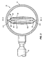
- is a section view taken along line 3-3 of
Fig. 1 . - Fig. 4
- is a section view taken along line 4-4 of
Fig. 3 . - Fig. 5a
- is an end view of the damper element of
Fig. 2 . - Fig. 5b
- is an enlarged section view of a portion of the damper element illustrated in
Fig. 5a . - Fig. 6
- is a section view taken along line 6-6 of
Fig. 5a . - Fig. 7
- is a section view taken along line 7-7 of
Fig. 6 . - Fig. 8
- is a section view similar to
Fig. 7 illustrating the damper element in a first substantially deformed state resulting from a first surrounding liquid pressure. - Fig. 9
- is a section view similar to
Fig. 8 illustrating the damper element in a second substantially deformed state resulting from a second surrounding liquid pressure. - Fig. 10
- is a section view similar to
Fig. 9 illustrating the damper element in a third substantially deformed state resulting from a third surrounding liquid pressure. - Fig. 11
- illustrates a portion of a fuel rail, partially broken away, and containing a damper element.
- Fig. 12
- is perspective view, shown partially in section, of the damper element of
Fig. 11 . - Fig. 13
- is a section view of the damper element taken along line 13-13 of
Fig. 11 . - Fig. 14
- is a section view of the damper element taken along line 14-14 of
Fig. 12 . - Fig. 15
- is a section view similar to
Fig. 14 illustrating the damper element in a first substantially deformed state resulting from a first surrounding liquid pressure. - Fig. 16
- is a section view similar to
Fig. 15 illustrating the damper element in a second substantially deformed state resulting from a second surrounding liquid pressure. - Fig. 17
- is a section view similar to
Fig. 16 illustrating the damper element in a third substantially deformed state resulting from a third surrounding liquid pressure. - Fig. 18
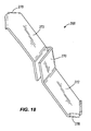
- is a perspective view of a retainer used with the damper element of
Figs. 11-17 inside the fuel rail as shown inFigs. 11-13 . - Fig. 19
- is a section view of a damper element, similar to the damper element of
Figs. 11-17 . - Before any embodiments of the invention are explained in detail, it is to be understood that the invention is not limited in its application to the details of construction and the arrangement of components set forth in the following description or illustrated in the following drawings. The invention is capable of other embodiments and of being practiced or of being carried out in various ways. Also, it is to be understood that the phraseology and terminology used herein is for the purpose of description and should not be regarded as limiting. The use of "including," "comprising," or "having" and variations thereof herein is meant to encompass the items listed thereafter and equivalents thereof as well as additional items. Unless specified or limited otherwise, the terms "mounted," "connected," "supported," and "coupled" and variations thereof are used broadly and encompass both direct and indirect mountings, connections, supports, and couplings. Further, "connected" and "coupled" are not restricted to physical or mechanical connections or couplings.
-
Fig. 1 illustrates afuel rail assembly 10 including afuel rail 14 and a plurality offuel injectors 18 coupled to thefuel rail 14. The illustratedfuel rail 14 is configured to contain fuel pressurized from about 4 bar to about 150 bar above the ambient pressure. Adamper element 22 is positioned inside thefuel rail 14 for damping pressure pulsations in the fuel that are created by the operation of thefuel injectors 18. Thedamper element 22 is well-suited for operation within the pressure ranges set forth above, and the damping characteristics of thedamper element 22 will not be significantly affected by the standard operating temperatures within thefuel rail 14. Additionally, the illustrateddamper element 22 can also be used in lower pressure fuel rail systems typically operating at about 2 to about 4 bar above ambient pressure, and provides a more efficient alternative to existing damper elements. -
Figs. 2-10 illustrate thedamper element 22 in greater detail. While thedamper element 22 is illustrated as being used in conjunction with a fuel-injected fuel system, it is to be understood that thedamper element 22 can also be used in other applications where pressure pulsations within a liquid require damping. - With initial reference to
Figs. 2 and7 , thedamper element 22 includes anouter tube 26 having anouter surface 30 and aninner surface 34 defining an interior cavity. Thedamper element 22 also includes aninner tube 38 having anouter surface 42 and aninner surface 46. Theinner tube 38 is positioned within the interior cavity of theouter tube 26 such that at least one chamber for receiving a compressible gas is defined between theinner surface 34 of theouter tuber 26 and theouter surface 42 of theinner tube 38. In the illustrated embodiment, there are twomain chambers inner surface 34 of theouter tube 26 and theouter surface 42 of theinner tube 38. The twochambers outer tubes Fig. 7 , theouter tube 26 includes opposite convexly-contouredside portions 58 interconnected by oppositearcuate portions 62. Theinner tube 38 includes opposite concavely-contouredside portions 66 interconnected by oppositearcuate portions 70. For purposes of this description, the terms convex and concave describe the curvature taken with respect to the outer surfaces of thetubes first chamber 50 is defined between one of the convexly-contouredside portions 58 of theouter tube 26 and one of the concavely-contouredside portions 66 of theinner tube 38. Thesecond chamber 54 is defined between the other of the convexly-contouredside portions 58 of theouter tube 26 and the other of the concavely-contouredside portions 66 of theinner tube 38. More generally, the convexly-contouredside portions 58 of theouter tube 26 define wall portions that extend away from theinner tube 38, and the concavely-contouredside portions 66 of theinner tube 38 define wall portions that extend away from theouter tube 26. These oppositely-extending wall portions together define therespective chambers - In the illustrated embodiment, and with continued reference to
Fig. 7 , theinner tube 38 is press-fit into the interior cavity of theouter tube 26 to define at least two, and more likely four longitudinally-extending zones ofcontact 74a-d between theinner surface 34 of theouter tube 26 and theouter surface 42 of theinner tube 38. The zones ofcontact chamber 50 and the zones ofcontact chamber 54. As best shown inFig. 7 , twosmall chambers arcuate portions 62 of theouter tube 26 and the respective oppositearcuate portions 70 of theinner tube 38. The zones ofcontact chamber 78, while the zones ofcontact chamber 82. - In the illustrated embodiment, the zones of
contact 74a-d are formed by the press-fit operation only, and no welding or other bonding techniques are utilized. Such additional bonding in the areas of the zones ofcontact 74a-d could result in increased stresses created in thedamper element 22. In addition, while the four zones ofcontact 74a-d could be reduced to two zones of contact by having the inner andouter tubes contact contact damper element 22, and as such, would not be as advantageous as the illustrated construction incorporating thesmall chambers contact points - As shown in
Figs. 2 and6 , thedamper element 22 has afirst end 86 defined by the first ends of the inner andouter tubes second end 90 defined by the second ends of the inner andouter tubes Figs. 5a and5b , the respective ends of the inner andouter tubes chambers Fig. 5b , asealing layer 94 is formed between the outer andinner tubes chambers ends chambers smaller chambers - The assembled
damper element 22 defines an exterior surface (i.e., theouter surface 30 of the outer tube 26) and an interior surface (i.e., theinner surface 46 of the inner tube 38). As shown inFigs. 7-10 , when thedamper element 22 is inserted into thefuel rail 14, the exterior surface is surrounded by liquid fuel in thefuel rail 14. Additionally, the interior surface of thedamper element 22 defines apassageway 98 extending through thedamper element 22 and that is filled by the liquid fuel in thefuel rail 14. Thus, unlike prior art damper elements which define a single, relatively voluminous enclosed gas chamber surrounded on the outside by the liquid fuel, thedamper element 22 defines at least two relatively less voluminous,distinct chambers Fig. 6 ) of thedamper element 22. Thechambers passageway 98 such that bothchambers damper element 22 and within thepassageway 98 of thedamper element 22. - With the two
chambers passageway 98, thedamper element 22 has four surfaces that move and deform in response to pressure changes in the fuel. This is twice as many moving surfaces as found on prior art, single-chamber, generally oval-shaped dampers having only two moving surfaces. More moving surfaces and more gas chambers allow a greater volume change of the gas in thechambers damper element 22 will experience about two times more gas volume change per bar of fuel pressure change, thereby significantly improving the damping characteristics of thedamper element 22 in relation to prior art dampers. - The
damper element 22 achieves this increased gas volume change capacity while displacing significantly less fuel than prior art, single-chamber dampers having generally the same outer dimensions. Specifically, the total gas volume in the twochambers passageway 98 between the two chambers, which does not displace any fuel, but rather is filled with the fuel.Fig. 7 illustrates thedamper element 22 within the fuel rail when the surrounding fuel is at the ambient pressure (i.e., when the fuel in thefuel rail 14 is not pressurized).Fig. 8 illustrates thedamper element 22 in its deformed state when the fuel in thefuel rail 14 is pressurized to the operating pressure (e.g., to about eight bar above ambient pressure). Notice that inFig. 8 , the fuel displacement by the gas volume in thechambers Fig. 7 just by pressuring the fuel to the normal operating pressure. - The smaller fuel displacement achieved with the
damper element 22 means that there is more fuel in thefuel rail 14. Increasing the amount of fuel in thefuel rail 14 reduces the risk of "hot start" and "hot drive away" problems. These are problems that occur when a percentage of the fuel in thefuel rail 14 changes from liquid to vapor. The injectors require liquid fuel to properly supply the combustion chambers, and too much fuel vapor in therail 14 can be problematic. Because thedamper element 22 displaces less fuel than prior art dampers, there is more liquid fuel in the fuel rail. With more liquid fuel, there is a better likelihood that the engine will be able to run long enough with the liquid fuel to properly pressurize and cool thefuel rail 14, thereby allowing any fuel vapor to return to the liquid state. Increasing the amount of fuel in thefuel rail 14 is also advantageous because the fuel in thefuel rail 14 is a compressible liquid that can contribute to pressure pulsation damping. -
Fig. 9 illustrates thedamper element 22 in its deformed state when the fuel pressure in thefuel rail 14 is further increased from the pressure shown inFig. 8 due to pressure pulsations in the fuel rail 14 (e.g., to about eleven bar above ambient pressure).Fig. 10 illustrates thedamper element 22 in its deformed state when the fuel pressure in thefuel rail 14 is further increased toward the maximum expected fuel pressure (e.g., to about 150 bar above ambient pressure). Thedamper element 22 allows theinner tube 38 and theouter tube 26 walls to come very close together without overstressing the metal tubes. This allows the gas in thechambers metal tubes - The
tubes - The
damper element 22 makes use of all three available "springs" in the fuel rail system to dampen pressure pulsations. First, as discussed above, by displacing less fuel than prior art fuel rails, thedamper element 22 makes use of a greater fuel spring present in the increased amount of compressible fuel in thefuel rail 14. Second, thedamper element 22 makes use of the metal spring that is the bending and deformation of the inner andouter tubes damper element 22 makes greatly increased use of the gas spring that is the compression of the gas housed within thechambers damper element 22 uses these three "springs," and most significantly, the combined metal spring and gas spring to balance the outside forces of the fuel pressure acting on thedamper element 22. - The metal spring has a linear spring rate, while the gas spring has a non-linear spring rate. The linear spring rate of the metal tube surfaces contributes significantly to increasing the volume change in the
chambers chambers damper element 22 will be excited by external vibration inputs is greatly reduced. This enables thedamper element 22 to dampen more effectively. - While the damping characteristics of prior art single-chamber dampers are mainly a function of the metal spring of the moving damper walls, the
damper element 22 relies much more on the increased gas spring capacity that exists due to the presence of the twogas chambers tubes volume chambers damper element 22. The increased gas spring helps insure that the thinner metal will not be overstressed and that it will still meet the fatigue life for thedamper element 22. In the illustrated embodiment, the fatigue endurance requirement is based on 1,000,000 fuel pressure cycles taken from ambient pressure to the fuel rail operating pressure and back to the ambient pressure. Because of the thinner tube walls and the increased gas spring, the rate of acceleration of the damper element moving surfaces is increased, providing adamper element 22 that is extremely sensitive to pressure changes in thefuel rail 14 and that quickly reacts to these pressure changes. Additionally, the low mass of the moving walls combined with the high spring rate of thedamper element 22 produces a damper that has a very high natural frequency that will be more effective at damping the pressure pulsations in the fuel rail. - The inner and
outer tubes damper element 22 are designed using finite element analysis (FEA) or other suitable modeling techniques to achieve the desired cross-sectional tube configurations. Starting with a generally oval shape (as shown inFig. 2 at the end 90) for theinner tube 38, a small external pressure (P1) is applied to the FEA model to determine the maximum stress (S1max) in this model as a function of this small external pressure (P1). The fatigue endurance strength (ES) based on the tube material being modeled is known. Next, a new external pressure (P2) substantially equal to ((ES / S1max) *P1) is applied to the model to determine the deflection that will ultimately define the concavely-contouredside portions 66. Then, if it is verified that the maximum stress in this FEA model at the new pressure (P2) is substantially equal to the fatigue endurance strength (ES) of the material, the shape of theinner tube 38 that was created by the external pressure (P2) will be used for the manufacturedinner tube 38 in its free state (i.e., the shape with no pressure acting on the inner tube 38). To verify that this resultant cross-sectional shape for theinner tube 38 is appropriate, it is then modeled with an internal pressure (P2) applied to the FEA model with the following results: (1) the maximum stress (S1max) was equal to the fatigue endurance strength (ES); and (2) the shape returned to the original generally oval shape (as shown inFig. 2 at the end 90). Theinner tube 38 can then be formed to this shape via extrusion or other suitable forming processes. If theinner tube 38 is extruded, but yet requires a longitudinal weld, the weld should be located at the lowest stress area of thetube 38. - The
outer tube 26 is designed similarly. Starting with a generally oval shape (as shown inFig. 2 at the end 90) for theouter tube 26, a small internal pressure (P1) is applied to the FEA model to determine the maximum stress (S1max) in this model as a function of this small internal pressure (P1). The fatigue endurance strength (ES) based on the tube material being modeled is known. Next, a new internal pressure (P2) substantially equal to ((ES / S1max) *P1) is applied to the model to determine the deflection that will ultimately define the convexly-contouredside portions 58. Then, if it is verified that the maximum stress in this FEA model at the new pressure (P2) is substantially equal to the fatigue endurance strength (ES) of the material, the shape of theouter tube 26 that was created by the internal pressure (P2) will be used for the manufacturedouter tube 26 in its free state (i.e., the shape with no pressure acting on the outer tube 26). To verify that this resultant cross-sectional shape for theouter tube 26 is appropriate, it is then modeled with an external pressure (P2) applied to the FEA model with the following results: (1) the maximum stress (S1max) was equal to the fatigue endurance strength (ES); and (2) the shape returned to the original generally oval shape (as shown inFig. 2 at the end 90). Theouter tube 26 can then be formed to this shape via extrusion or other suitable forming processes. As with theinner tube 38, if theouter tube 26 is extruded, but yet requires a longitudinal weld, the weld should be located at the lowest stress area of thetube 26. - This process can be remodeled for each change to the height, thickness, and/or width of each
tube damper element 22 for package size and for the lowest ratio of change in displaced volume of thedamper element 22 to change in pressure measured at the operating pressure of thefuel rail 14. - With this design method, each point on the inner and
outer tubes damper element 22 can be optimized for the operating pressure of thespecific fuel rail 14 in which thedamper element 22 will be used. The thickness and shapes of thetubes damper element 22. The design intent is to operate thedamper element 22 at the endurance stress level for both the inner andouter tubes chambers outer tubes chambers chambers - The design is optimized by getting the most metal spring possible from the thin metal tube walls, and then having the gas spring compensate for the remaining pressure differences. At pressures of more than forty bars above ambient, the thin metal walls of the
damper element 22 provide little or no significant resistance to deflection, however, the increased gas pressure in thechambers - With reference to
Figs. 1 ,3 , and4 , thedamper element 22 is positioned within thefuel rail 14 using resilient locating members 106 (only one is shown). The illustrated locatingmember 106 is made of spring steel and includesopposite end portions 110 configured to be biased into engagement with the inner surface of thefuel rail 14. Aresilient body portion 114 extends between theend portions 110 and is configured to be received in thepassageway 98 of the damper element and to engage theinner surface 46 of theinner tube 38, thereby supporting and positioning thedamper element 22 within thefuel rail 14. While the locatingmember 106 is shown as having a square cross-section, those skilled in the art will understand that other suitable cross-sectional shapes (e.g., round, rectangular, etc.) can also be substituted. Additionally, those skilled in the art will understand that alternative methods of positioning thedamper element 22 in thefuel rail 14 can also be used. -
Figs. 11-17 illustrate afuel rail assembly 210 or portions thereof including afuel rail 214 and a plurality offuel injectors 218 coupled to thefuel rail 214. The illustratedfuel rail 214 is configured to contain pressurized fuel and may be similar to thefuel rail 14, which is discussed in detail above. Adamper element 222 embodying the invention is positioned inside thefuel rail 214 for damping pressure pulsations in the fuel that are created by the operation of thefuel injectors 218. In many aspects, thedamper element 222 is similar to thedamper element 22 illustrated inFigs. 1-10 and discussed above, and reference is hereby made to the above description insofar as some of the commonalities are not specifically reiterated below with respect to thedamper element 222 shown inFigs. 11-17 . In addition, although some of the details below that describe thedamper element 222 ofFigs. 11-17 are not shared with thedamper element 22 ofFigs. 1-10 , much of the description below points out features that are also found in thedamper element 22 ofFigs. 1-10 , although they may not be described with specific reference thereto. -
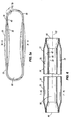
Figs. 12-17 illustrate thedamper element 222 in greater detail. Thedamper element 222 includes afirst side 224 and a secondopposing side 226 and further defines achamber 230, substantially an entire cross-section of which is formed by a pair of convexly-curved wall portions wall portions damper element 222, the term convex describes the curvature with respect to the respectiveouter surfaces wall portions wall portions Fig. 14 ). Thus, thewall portions inner surfaces wall portions chamber 230 generally follow the curvature defined by theouter surfaces wall portions wall portions Fig. 14 to define a volume within thechamber 230. - The radius of each of the
wall portions 234, 236 (as viewed inFig. 14 ) is between about 50 millimeters and about 100 millimeters when thedamper element 222 is in an unstressed state. In the illustrated embodiment, each of thewall portions damper element 222 is in an unstressed state. The shape of thewall portions damper element 222 is exposed to external fuel pressures as further described below. Whether stressed or unstressed, the radii of thewall portions damper element 222. - A
first flange portion 242A extends from thefirst wall portion 234 in a direction away from thechamber 230. Asecond flange portion 244A extends from thesecond wall portion 236 in a direction away from thechamber 230 and substantially parallel to thefirst flange portion 242A. The first andsecond flange portions chamber 230 along oneedge 248. In some embodiments, theflange portions flange portions second sides respective flange portions chamber 230 and opposite the first andsecond flange portions chamber 230 along the second edge 250). - In the embodiment illustrated in
Figs. 12-17 , thefirst side 224 and thesecond side 226 are formed separately from each other and joined together as described to define thechamber 230. For example, in some embodiments, thefirst side 224 and thesecond side 226 are stamped parts and thefirst side 224 is formed as a separate stamping from the second side 226 (either from the same sheet or different sheets of material). - The first and
second flange portions longitudinal contact zone 254 between the first andsecond sides additional flange portions longitudinal contact zone 258 between the first andsecond sides second edges second sides first end 262 and a second end 264 (Fig. 12 ), thus sealing thechamber 230 from the exterior of thedamper element 222. - As described above, the
chamber 230 is enclosed and as such is operable to contain a gaseous substance (referred to herein as "the gas"). The gas may primarily consist of a single element, such as nitrogen, argon, or helium, however thedamper element 222 exhibits satisfactory performance with thechamber 230 containing an amount of air. When referring to the gas, the amount can be determined by mass or weight rather than by volume. The volume of thechamber 230 is configured to be dynamic during operation of thedamper element 222 in thefuel rail 214 as discussed above in reference to thedamper element 22 ofFigs. 1-10 and as described in brief detail further below with specific reference to thedamper element 222 ofFigs. 11-17 . Although thechamber 230 is subject to a change in cross-sectional area (and a resulting change in volume) during operation, the design volume of the chamber 230 (unstressed) is an important factor in relation to the damping performance of the dampingelement 222. The volume cannot be any larger than the maximum operating volume based on the compliance of the device and the maximum system pressure the device will be used in. For example, the unstressed cross-sectional area (i.e., the cross-sectional area of thechamber 230 when thedamper 222 is not exposed to pressures in excess of atmospheric pressure-seeFig. 14 ) of thechamber 230 can be between about 0.5 square millimeters and about 5.0 square millimeters. In some embodiments, the unstressed cross-sectional area (Fig. 14 ) of thechamber 230 is about 4.0 square millimeters. The unstressed internal width of the chamber 230 (i.e., the linear dimension between the first and secondlongitudinal contact zones 254, 258) is between about 9.6 millimeters and about 15.6 millimeters. In some embodiments, the unstressed internal width of thechamber 230 is about 14.4 millimeters. The overall length of thedamper element 222 is between about 48 and 52 times the thickness of the first andsecond wall portions 234, 236 (which can range between about 0.20 millimeters and about 0.30 millimeters). In one construction, the overall length of thedamper element 222 is about 230 millimeters. - Each of the first and second
longitudinal contact zones respective flanges Figs. 14-17 ) of about 1 millimeter. The width of 1 millimeter provides a suitable area along which the first andsecond sides longitudinal contact zones chamber 230 to obtain the desired damping performance while remaining smaller than the internal diameter of thefuel rail 214. The first andsecond sides longitudinal contact zones damper element 222 does not maintain a static shape during damping (seeFigs. 15-17 ). As fuel pressure outside thechamber 230 increases, the first andsecond wall portions second edges - As shown in
Figs. 11-13 , thedamper element 222 is located centrally within thefuel rail 214 by a pair ofretainers 268, one of which is shown in greater detail inFig. 18 . Eachretainer 268 may be formed from a flat sheet (e.g., by stamping, bending, etc.). Eachretainer 268 includes acentral attachment portion 270 and a pair ofextension portions 272 extending therefrom in opposite directions. Theattachment portions 270 of theretainers 268 are pressed onto the respective first and second ends 262, 264 of thedamper element 222. Each of theextension portions 272 terminates in a curledtip 276 that is adjacent the inner wall of thefuel rail 214 when thedamper element 222 is in place. Although thedamper element 222 may not be prevented from moving axially within thefuel rail 214 or rotating within thefuel rail 214, theretainers 268 generally keep thedamper element 222 from contacting the inner wall of thefuel rail 214. -
Figs. 14-17 illustrate thedamper element 222 in various stages of operation relative to increasing fuel pressures within thefuel rail 214. InFig. 14 , thedamper element 222 is in an unstressed state while the fuel within thefuel rail 214 is not substantially pressurized above atmospheric pressure (e.g., during periods of non-use).Fig. 15 illustrates thedamper element 222 in a first deformed state corresponding to a first positive pressure within thefuel rail 214.Fig. 16 illustrates thedamper element 222 in a second deformed state corresponding to a second positive pressure within thefuel rail 214 that is greater than the first positive pressure.Fig. 17 illustrates thedamper element 222 in a third deformed state corresponding to a third positive pressure within thefuel rail 214 that is greater than the second positive pressure. As thedamper element 222 is deformed by external pressure to substantially flatten the first andsecond wall portions chamber 230, the overall width of the damper element 222 (between the first andsecond edges 248, 250) is substantially free to increase in compensation. Meanwhile, the gas within thechamber 230 experiences an increase in pressure in reaction to the pressure incident on thedamper element 222 from the surrounding fuel. - A
damper element 322 of a further embodiment is illustrated in cross-section inFig. 19 . Thedamper element 322 may be identical to thedamper element 222 ofFigs. 11-17 , except that thefirst side 324 and thesecond side 326 are formed from a single piece rather than being separate pieces joined together. For example, the first andsecond sides second wall portions chamber 330. First and secondrespective flange portions second sides contact zone 354 along afirst edge 348 of thedamper element 322. The first andsecond flange portions chamber 330, a fold crease defines a second longitudinally extendingcontact zone 358 between the first andsecond sides second edge 350 of thedamper element 322. No additional joining or sealing means are necessary along this side of thedamper element 322. The first andsecond sides damper element 322 are sealed at the respective ends as previously described. - Many of the aspects of the
damper elements Figs. 11-17 and19 , respectively, and described above, are common to thedamper element 22 shown inFigs. 1-10 . Although thedamper element 22 shown inFigs. 1-10 is formed from anouter tube 26 and aninner tube 38, each of thedual chambers damper 22 are similar to thesingle chambers respective damper elements Figs. 11-17 and19 . In this respect, many of the features described with particular reference to thedampers Figs 11-17 and19 are present in thedamper 22 ofFigs. 1-10 . - Various features and advantages of the invention are set forth in the following claims.
Claims (14)
- A damper element for damping pressure pulsations in a liquid, the damper element comprising:a first side including a first wall portion and a first flange portion extending from the first wall portion;a second side including a second wall portion and a second flange portion extending from the second wall portion, the second flange portion being joined with the first flange portion to define a first longitudinally extending contact zone along which the first and second sides are overlapped; anda gas-containing chamber formed solely by the first wall portion and the second wall portion, both of the first and second wall portions being convexly curved outwardly away from the gas-containing chamber.
- The damper element of claim 1, wherein the first side is formed as a separate piece from the second side.
- The damper element of claim 2, wherein the first side is stamped from a first sheet and the second side is stamped from a second sheet.
- The damper element of claim 3, wherein each of the first and second sides are stamped with a pair of flange portions, the flange portions of the first side being joined with the flange portions of the second side to define first and second longitudinally extending contact zones.
- The damper element of claim 1, wherein the first wall portion is convexly curved outwardly away from the gas-containing chamber with a substantially constant radius.
- The damper element of claim 5, wherein the second wall portion is substantially identical to the first wall portion and oriented in a mirrored relation to the first wall portion.
- The damper element of claim 1, wherein the cross-sectional area of the gas-containing chamber is about 4 square millimeters when the damper element is in an unstressed state.
- The damper element of claim 1, wherein the first side and the second side are formed as a single piece of material folded upon itself.
- The damper element of claim 8, wherein the damper element includes a fold crease defining a second longitudinally extending contact zone.
- A method of producing a damper element having a sealed, gas-containing chamber for damping pressure pulsations in a fuel rail, the method comprising:providing a first side of the damper element to include a first wall portion and a first flange portion extending from the first wall portion, the first wall portion being convexly curved outwardly away from the gas-containing chamber;providing a second side of the damper element to include a second wall portion and a second flange portion extending from the second wall portion, the second wall portion being convexly curved outwardly away from the gas-containing chamber;overlapping the first and second flange portions; andjoining the first and second flange portions to define a first longitudinally extending contact zone, a cross-section of the gas-containing chamber being formed solely by the first and second wall portions.
- The method of claim 10, wherein the first and second sides of the damper element are stamped in a single sheet, and the method further comprising folding the sheet upon itself.
- The method of claim 11, wherein the damper element includes a fold crease defining a second longitudinally extending contact zone.
- The method of claim 10, wherein the first and second sides of the damper element are stamped separately, each of the first and second sides being formed with a pair of flange portions, the flange portions of the first side being joined with the flange portions of the second side to define first and second longitudinally extending contact zones.
- The method of claim 10, further comprising forming both the first wall portion and the second wall portion with substantially constant and equivalent radii.
Applications Claiming Priority (1)
| Application Number | Priority Date | Filing Date | Title |
|---|---|---|---|
| US11/955,921 US7497202B2 (en) | 2004-10-15 | 2007-12-13 | Hydraulic damper element |
Publications (1)
| Publication Number | Publication Date |
|---|---|
| EP2071179A1 true EP2071179A1 (en) | 2009-06-17 |
Family
ID=40445240
Family Applications (1)
| Application Number | Title | Priority Date | Filing Date |
|---|---|---|---|
| EP08021138A Withdrawn EP2071179A1 (en) | 2007-12-13 | 2008-12-05 | Hydraulic damper element |
Country Status (3)
| Country | Link |
|---|---|
| US (1) | US7497202B2 (en) |
| EP (1) | EP2071179A1 (en) |
| JP (1) | JP2009144923A (en) |
Cited By (1)
| Publication number | Priority date | Publication date | Assignee | Title |
|---|---|---|---|---|
| WO2014086522A1 (en) * | 2012-12-06 | 2014-06-12 | Robert Bosch Gmbh | High-pressure accumulator for a fuel injection system and method for the assembly of a high-pressure accumulator |
Families Citing this family (22)
| Publication number | Priority date | Publication date | Assignee | Title |
|---|---|---|---|---|
| AT503660B1 (en) * | 2006-06-13 | 2007-12-15 | Bosch Gmbh Robert | DEVICE FOR INJECTING FUEL IN THE COMBUSTION ENGINE OF AN INTERNAL COMBUSTION ENGINE |
| EP2110542A1 (en) * | 2008-04-17 | 2009-10-21 | Continental Automotive GmbH | Fuel rail of a combustion engine |
| US7694664B1 (en) | 2009-01-09 | 2010-04-13 | Robert Bosch Gmbh | Fuel rail damper |
| US8235074B2 (en) * | 2010-02-25 | 2012-08-07 | Masami Sakita | Pope and pipe fittings |
| KR101332759B1 (en) * | 2012-06-07 | 2013-11-25 | (주)동보 | Inner damper fixing for fuel distributer of vehicle |
| US9074565B2 (en) * | 2012-07-16 | 2015-07-07 | Denso International America, Inc. | Damped fuel delivery system |
| CN202746072U (en) * | 2012-08-24 | 2013-02-20 | 大陆汽车电子(长春)有限公司 | Fuel oil guide rail assembly and built-in damper retainer applied to fuel oil guide rail assembly |
| US9518544B2 (en) * | 2013-03-19 | 2016-12-13 | Delphi Technologies, Inc. | Fuel rail with pressure pulsation damper |
| GB201319578D0 (en) * | 2013-11-06 | 2013-12-18 | Delphi Tech Holding Sarl | Hydraulic damper |
| GB201400864D0 (en) * | 2014-01-20 | 2014-03-05 | Delphi Int Operations Luxembourg Sarl | High pressure fuel pump |
| WO2017132426A2 (en) * | 2016-01-27 | 2017-08-03 | Schlumberger Technology Corporation | Modular configurable wellsite surface equipment |
| WO2018085741A1 (en) | 2016-11-04 | 2018-05-11 | Schlumberger Technology Corporation | Pressure exchanger pressure oscillation source |
| WO2018085745A1 (en) | 2016-11-04 | 2018-05-11 | Schlumberger Technology Corporation | Pressure exchanger wear prevention |
| US10975677B2 (en) | 2016-11-04 | 2021-04-13 | Schlumberger Technology Corporation | Pressure exchanger low pressure flow control |
| US11346372B2 (en) | 2016-11-04 | 2022-05-31 | Schlumberger Technology Corporation | Split stream operations with pressure exchangers |
| US10995774B2 (en) | 2016-11-04 | 2021-05-04 | Schlumberger Technology Corporation | Pressure exchanger with pressure ratio |
| US11157025B2 (en) * | 2016-11-04 | 2021-10-26 | Schlumberger Technology Corporation | Pressure exchanger manifold resonance reduction |
| US10690101B2 (en) * | 2017-09-15 | 2020-06-23 | Indian Motorcycle International, LLC | Wheeled vehicle |
| DE102018209787A1 (en) * | 2018-06-18 | 2019-12-19 | Robert Bosch Gmbh | Fuel distributor for internal combustion engines |
| US10731611B2 (en) * | 2018-12-21 | 2020-08-04 | Robert Bosch Llc | Fuel rail damper with locating features |
| DE102019101135A1 (en) * | 2019-01-17 | 2020-07-23 | Bayerische Motoren Werke Aktiengesellschaft | Internal combustion engine with a fuel injection system |
| DE102019103041B4 (en) * | 2019-02-07 | 2022-12-29 | Dr. Ing. H.C. F. Porsche Aktiengesellschaft | Collector pressure line for a fuel injection system of an internal combustion engine |
Citations (4)
| Publication number | Priority date | Publication date | Assignee | Title |
|---|---|---|---|---|
| GB890895A (en) * | 1959-05-21 | 1962-03-07 | Su Carburetter Co Ltd | Improved means for securing regular flow from pumps |
| US5617827A (en) | 1995-12-26 | 1997-04-08 | General Motors Corporation | Fuel rail |
| US6463911B1 (en) * | 2002-01-14 | 2002-10-15 | Visteon Global Technologies, Inc. | Fuel pressure damper |
| US20060081220A1 (en) | 2004-10-15 | 2006-04-20 | Robert Bosch Gmbh | Hydraulic damper element |
Family Cites Families (57)
| Publication number | Priority date | Publication date | Assignee | Title |
|---|---|---|---|---|
| US1058572A (en) * | 1912-03-11 | 1913-04-08 | John K Finlay | Attachment for water-pipes. |
| US2409304A (en) * | 1943-04-01 | 1946-10-15 | Joseph I Morrison | Compressible core for cooling pipes |
| US2530190A (en) * | 1945-12-15 | 1950-11-14 | Eastman Kodak Co | Surge chamber |
| US2599325A (en) * | 1946-11-22 | 1952-06-03 | Lawrence H Fritzberg | Conduit construction |
| US3227147A (en) * | 1959-07-15 | 1966-01-04 | Gossiaux Camille | Shock absorbing tubing for diesel engine fuel injection systems |
| US3154037A (en) * | 1960-12-13 | 1964-10-27 | Mayrath Martin | Apparatus for anchoring the seams of lock seam tubing |
| US4056679A (en) * | 1976-09-27 | 1977-11-01 | I-T-E Imperial Corporation | Sodium filled flexible transmission cable |
| US4154264A (en) * | 1977-11-10 | 1979-05-15 | Schaller Hilary A | Hydraulic shock suppressor |
| DE2829057A1 (en) * | 1978-07-01 | 1980-01-10 | Bosch Gmbh Robert | FUEL INJECTION SYSTEM |
| US4328836A (en) * | 1980-10-14 | 1982-05-11 | Deere & Company | Pressure vessel |
| DE3119131C2 (en) * | 1981-05-14 | 1983-06-16 | Robert Bosch Gmbh, 7000 Stuttgart | Damper element |
| US4651781A (en) * | 1984-02-02 | 1987-03-24 | Northrop Corporation | Distributed accumulator |
| DE3432727A1 (en) * | 1984-05-10 | 1985-11-14 | Robert Bosch Gmbh, 7000 Stuttgart | FUEL SUPPLY PIPE |
| US4649884A (en) * | 1986-03-05 | 1987-03-17 | Walbro Corporation | Fuel rail for internal combustion engines |
| DE8710738U1 (en) * | 1986-06-07 | 1987-12-10 | Mitsuba Electric Mfg. Co., Ltd., Kiryu, Gumma | Pulsation protection element for a pump |
| FR2602283B1 (en) * | 1986-08-04 | 1988-10-21 | Peugeot | METHOD FOR MANUFACTURING A HYDROPNEUMATIC ACCUMULATOR |
| US4823844A (en) * | 1987-11-02 | 1989-04-25 | Proprietary Technology, Inc. | Fluid pressure surge damper for a fluid system |
| US4782570A (en) * | 1987-11-16 | 1988-11-08 | General Motors Corporation | Fabrication and assembly of metal catalytic converter catalyst substrate |
| DE3842298A1 (en) | 1988-12-16 | 1990-06-21 | Aeroquip Gmbh | Device for damping pressure fluctuations in largely rigid pipelines through which fluid flows |
| US5058627A (en) * | 1989-04-10 | 1991-10-22 | Brannen Wiley W | Freeze protection system for water pipes |
| JPH0754612Y2 (en) * | 1989-06-06 | 1995-12-18 | 臼井国際産業株式会社 | Fuel delivery pipe |
| DE4128465C1 (en) * | 1991-08-28 | 1993-02-25 | Mercedes-Benz Aktiengesellschaft, 7000 Stuttgart, De | |
| DE4315256A1 (en) * | 1993-05-07 | 1994-11-10 | Mtu Muenchen Gmbh | Device for distributing and supplying and removing a coolant to a wall of a turbo, in particular turbo ramjet engine |
| US5374169A (en) * | 1993-09-07 | 1994-12-20 | Walbro Corporation | Fuel pump tubular pulse damper |
| US5607035A (en) * | 1994-10-13 | 1997-03-04 | Delphi France Automotive Systems | Hydraulic damper |
| GB9323047D0 (en) * | 1993-11-09 | 1994-01-05 | Acg France | A method of forming a suspension strut |
| DE4341368A1 (en) * | 1993-12-04 | 1995-06-08 | Bosch Gmbh Robert | Damper for pressure oscillations in IC engine fuel circuit |
| US5538043A (en) * | 1994-06-29 | 1996-07-23 | Salazar; Dennis R. | Method and apparatus for preventing pipe damage |
| GB2294523B (en) * | 1994-10-27 | 1997-11-05 | Acg Deutschland Gmbh | Hydraulic damper |
| US5505181A (en) * | 1995-02-13 | 1996-04-09 | Siemens Automotive Corporation | Integral pressure damper |
| JPH09292090A (en) * | 1996-04-26 | 1997-11-11 | Shimizu Corp | Air bag in underwater sound silencer |
| US5709248A (en) * | 1996-09-30 | 1998-01-20 | Caterpillar Inc. | Internal accumulator for hydraulic systems |
| US5845621A (en) * | 1997-06-19 | 1998-12-08 | Siemens Automotive Corporation | Bellows pressure pulsation damper |
| US5896843A (en) * | 1997-11-24 | 1999-04-27 | Siemens Automotive Corporation | Fuel rail damper |
| JPH11294294A (en) * | 1998-04-15 | 1999-10-26 | Toyoda Gosei Co Ltd | Fuel delivery pipe |
| US5894861A (en) * | 1998-04-23 | 1999-04-20 | Siemens Automotive Corporation | Damper dry ice charge |
| US6032651A (en) * | 1998-05-28 | 2000-03-07 | Siemens Automotive Corporation | Fuel rail damper |
| US6205979B1 (en) * | 1998-11-24 | 2001-03-27 | Robert Bosch Corporation | Spring locator for damping device |
| US6418909B2 (en) * | 1998-11-24 | 2002-07-16 | Robert Bosch Corporation | Low cost hydraulic damper element and method for producing the same |
| DE19934357A1 (en) * | 1999-07-22 | 2001-01-25 | Bosch Gmbh Robert | Flat tube damper for pressure oscillations in car fuel hoses comprises narrow tube with internal chamber, at least part of the tube wall being deformed by pressure of fuel to alter cross-section of chamber |
| US6314942B1 (en) * | 2000-04-25 | 2001-11-13 | Siemens Automotive Corporation | Fuel pressure dampening element |
| US6390131B1 (en) * | 2000-09-15 | 2002-05-21 | Siemens Automotive Corporation | Retaining clip and assembly for internal dampening element |
| US6371083B1 (en) * | 2000-11-20 | 2002-04-16 | Robert Bosch Corporation | Self-damping manifold |
| JP4240835B2 (en) * | 2001-03-29 | 2009-03-18 | 株式会社日本自動車部品総合研究所 | Fuel injection device for internal combustion engine |
| US6513500B2 (en) * | 2001-04-02 | 2003-02-04 | Delphi Technologies, Inc. | Fuel rail damping device |
| JP2003083199A (en) * | 2001-09-05 | 2003-03-19 | Piolax Inc | Pulsation damper for fuel delivery pipe |
| US6651627B2 (en) * | 2001-12-12 | 2003-11-25 | Millennium Industries Corp. | Fuel rail pulse damper |
| JP3974392B2 (en) * | 2001-12-13 | 2007-09-12 | 臼井国際産業株式会社 | Fuel delivery pipe and its manufacturing method |
| US6672286B2 (en) * | 2001-12-14 | 2004-01-06 | Siemens Automotive Corporation | Corrugated fuel rail damper |
| JP3823060B2 (en) * | 2002-03-04 | 2006-09-20 | 株式会社日立製作所 | High pressure fuel supply pump |
| JP3995974B2 (en) * | 2002-04-23 | 2007-10-24 | 三桜工業株式会社 | Fuel delivery pipe |
| US6761150B2 (en) * | 2002-11-05 | 2004-07-13 | Millennium Industries Corp. | Fuel rail flow-feed pulse damper |
| US6915786B2 (en) * | 2002-12-10 | 2005-07-12 | Dana Corporation | Damper for a fluid system |
| US7036487B2 (en) * | 2003-12-16 | 2006-05-02 | Delphi Technologies, Inc | Fuel rail pulse damper with integral strengthening rib |
| US6935314B2 (en) * | 2003-12-19 | 2005-08-30 | Millennium Industries Corp. | Fuel rail air damper |
| JP4173464B2 (en) * | 2004-05-12 | 2008-10-29 | 臼井国際産業株式会社 | Fuel delivery pipe |
| US7165535B2 (en) * | 2004-05-27 | 2007-01-23 | Delphi Technologies, Inc. | Fuel rail pulse damper with improved end crimp |
-
2007
- 2007-12-13 US US11/955,921 patent/US7497202B2/en not_active Expired - Fee Related
-
2008
- 2008-12-05 EP EP08021138A patent/EP2071179A1/en not_active Withdrawn
- 2008-12-11 JP JP2008315235A patent/JP2009144923A/en active Pending
Patent Citations (4)
| Publication number | Priority date | Publication date | Assignee | Title |
|---|---|---|---|---|
| GB890895A (en) * | 1959-05-21 | 1962-03-07 | Su Carburetter Co Ltd | Improved means for securing regular flow from pumps |
| US5617827A (en) | 1995-12-26 | 1997-04-08 | General Motors Corporation | Fuel rail |
| US6463911B1 (en) * | 2002-01-14 | 2002-10-15 | Visteon Global Technologies, Inc. | Fuel pressure damper |
| US20060081220A1 (en) | 2004-10-15 | 2006-04-20 | Robert Bosch Gmbh | Hydraulic damper element |
Cited By (1)
| Publication number | Priority date | Publication date | Assignee | Title |
|---|---|---|---|---|
| WO2014086522A1 (en) * | 2012-12-06 | 2014-06-12 | Robert Bosch Gmbh | High-pressure accumulator for a fuel injection system and method for the assembly of a high-pressure accumulator |
Also Published As
| Publication number | Publication date |
|---|---|
| US20080087253A1 (en) | 2008-04-17 |
| US7497202B2 (en) | 2009-03-03 |
| JP2009144923A (en) | 2009-07-02 |
Similar Documents
| Publication | Publication Date | Title |
|---|---|---|
| US7497202B2 (en) | Hydraulic damper element | |
| US6871635B2 (en) | Fuel rail damping device | |
| US6418909B2 (en) | Low cost hydraulic damper element and method for producing the same | |
| US8366421B2 (en) | Fluid pressure pulsation damper mechanism and high-pressure fuel pump equipped with fluid pressure pulsation damper mechanism | |
| US6314942B1 (en) | Fuel pressure dampening element | |
| US6205979B1 (en) | Spring locator for damping device | |
| JP5570226B2 (en) | Fuel rail damper | |
| US6390131B1 (en) | Retaining clip and assembly for internal dampening element | |
| JP4210970B2 (en) | Fuel delivery pipe | |
| WO2008073515A1 (en) | Fluid conduit assemble | |
| CN109070866B (en) | Pressure pulsation reducing device and pulsation damping component of hydraulic system | |
| JP4199710B2 (en) | Fuel delivery pipe | |
| US7341045B2 (en) | Hydraulic damper element | |
| JP2000329030A (en) | Fuel delivery pipe | |
| US6802297B2 (en) | Fuel rail damping device | |
| AU2003268584A1 (en) | Damper for a fluid system | |
| US7165535B2 (en) | Fuel rail pulse damper with improved end crimp | |
| JP3964691B2 (en) | Fuel delivery pipe | |
| CN106150803B (en) | Fuel supply system | |
| JP2007303384A (en) | Fuel delivery pipe | |
| KR20180099700A (en) | Components of a fuel injection system for a hydraulic device, particularly an internal combustion engine | |
| JP2002106438A (en) | Pulsation absorption system for fuel piping system | |
| JP4815409B2 (en) | Cylindrical member for vibration isolator and vibration isolator | |
| JP4206346B2 (en) | Fuel delivery assembly | |
| JP2004092571A (en) | Fuel delivery pipe |
Legal Events
| Date | Code | Title | Description |
|---|---|---|---|
| PUAI | Public reference made under article 153(3) epc to a published international application that has entered the european phase |
Free format text: ORIGINAL CODE: 0009012 |
|
| AK | Designated contracting states |
Kind code of ref document: A1 Designated state(s): AT BE BG CH CY CZ DE DK EE ES FI FR GB GR HR HU IE IS IT LI LT LU LV MC MT NL NO PL PT RO SE SI SK TR |
|
| AX | Request for extension of the european patent |
Extension state: AL BA MK RS |
|
| 17P | Request for examination filed |
Effective date: 20091217 |
|
| 17Q | First examination report despatched |
Effective date: 20100125 |
|
| AKX | Designation fees paid |
Designated state(s): DE FR GB IT |
|
| STAA | Information on the status of an ep patent application or granted ep patent |
Free format text: STATUS: THE APPLICATION IS DEEMED TO BE WITHDRAWN |
|
| 18D | Application deemed to be withdrawn |
Effective date: 20120424 |