EP2071156A1 - Brennstoffverteilungssystem für eine Gasturbine mit mehrstufiger Brenneranordnung - Google Patents
Brennstoffverteilungssystem für eine Gasturbine mit mehrstufiger Brenneranordnung Download PDFInfo
- Publication number
- EP2071156A1 EP2071156A1 EP08169482A EP08169482A EP2071156A1 EP 2071156 A1 EP2071156 A1 EP 2071156A1 EP 08169482 A EP08169482 A EP 08169482A EP 08169482 A EP08169482 A EP 08169482A EP 2071156 A1 EP2071156 A1 EP 2071156A1
- Authority
- EP
- European Patent Office
- Prior art keywords
- fuel
- distribution system
- distribution
- burner
- mass flow
- Prior art date
- Legal status (The legal status is an assumption and is not a legal conclusion. Google has not performed a legal analysis and makes no representation as to the accuracy of the status listed.)
- Granted
Links
Images
Classifications
-
- F—MECHANICAL ENGINEERING; LIGHTING; HEATING; WEAPONS; BLASTING
- F23—COMBUSTION APPARATUS; COMBUSTION PROCESSES
- F23R—GENERATING COMBUSTION PRODUCTS OF HIGH PRESSURE OR HIGH VELOCITY, e.g. GAS-TURBINE COMBUSTION CHAMBERS
- F23R3/00—Continuous combustion chambers using liquid or gaseous fuel
- F23R3/28—Continuous combustion chambers using liquid or gaseous fuel characterised by the fuel supply
- F23R3/34—Feeding into different combustion zones
- F23R3/346—Feeding into different combustion zones for staged combustion
-
- F—MECHANICAL ENGINEERING; LIGHTING; HEATING; WEAPONS; BLASTING
- F02—COMBUSTION ENGINES; HOT-GAS OR COMBUSTION-PRODUCT ENGINE PLANTS
- F02C—GAS-TURBINE PLANTS; AIR INTAKES FOR JET-PROPULSION PLANTS; CONTROLLING FUEL SUPPLY IN AIR-BREATHING JET-PROPULSION PLANTS
- F02C7/00—Features, components parts, details or accessories, not provided for in, or of interest apart form groups F02C1/00 - F02C6/00; Air intakes for jet-propulsion plants
- F02C7/22—Fuel supply systems
- F02C7/228—Dividing fuel between various burners
-
- F—MECHANICAL ENGINEERING; LIGHTING; HEATING; WEAPONS; BLASTING
- F02—COMBUSTION ENGINES; HOT-GAS OR COMBUSTION-PRODUCT ENGINE PLANTS
- F02C—GAS-TURBINE PLANTS; AIR INTAKES FOR JET-PROPULSION PLANTS; CONTROLLING FUEL SUPPLY IN AIR-BREATHING JET-PROPULSION PLANTS
- F02C9/00—Controlling gas-turbine plants; Controlling fuel supply in air- breathing jet-propulsion plants
- F02C9/26—Control of fuel supply
- F02C9/263—Control of fuel supply by means of fuel metering valves
-
- F—MECHANICAL ENGINEERING; LIGHTING; HEATING; WEAPONS; BLASTING
- F02—COMBUSTION ENGINES; HOT-GAS OR COMBUSTION-PRODUCT ENGINE PLANTS
- F02C—GAS-TURBINE PLANTS; AIR INTAKES FOR JET-PROPULSION PLANTS; CONTROLLING FUEL SUPPLY IN AIR-BREATHING JET-PROPULSION PLANTS
- F02C9/00—Controlling gas-turbine plants; Controlling fuel supply in air- breathing jet-propulsion plants
- F02C9/26—Control of fuel supply
- F02C9/32—Control of fuel supply characterised by throttling of fuel
- F02C9/34—Joint control of separate flows to main and auxiliary burners
-
- F—MECHANICAL ENGINEERING; LIGHTING; HEATING; WEAPONS; BLASTING
- F23—COMBUSTION APPARATUS; COMBUSTION PROCESSES
- F23N—REGULATING OR CONTROLLING COMBUSTION
- F23N1/00—Regulating fuel supply
-
- F—MECHANICAL ENGINEERING; LIGHTING; HEATING; WEAPONS; BLASTING
- F05—INDEXING SCHEMES RELATING TO ENGINES OR PUMPS IN VARIOUS SUBCLASSES OF CLASSES F01-F04
- F05D—INDEXING SCHEME FOR ASPECTS RELATING TO NON-POSITIVE-DISPLACEMENT MACHINES OR ENGINES, GAS-TURBINES OR JET-PROPULSION PLANTS
- F05D2270/00—Control
- F05D2270/30—Control parameters, e.g. input parameters
- F05D2270/31—Fuel schedule for stage combustors
-
- F—MECHANICAL ENGINEERING; LIGHTING; HEATING; WEAPONS; BLASTING
- F23—COMBUSTION APPARATUS; COMBUSTION PROCESSES
- F23N—REGULATING OR CONTROLLING COMBUSTION
- F23N2241/00—Applications
- F23N2241/20—Gas turbines
-
- F—MECHANICAL ENGINEERING; LIGHTING; HEATING; WEAPONS; BLASTING
- F23—COMBUSTION APPARATUS; COMBUSTION PROCESSES
- F23R—GENERATING COMBUSTION PRODUCTS OF HIGH PRESSURE OR HIGH VELOCITY, e.g. GAS-TURBINE COMBUSTION CHAMBERS
- F23R2900/00—Special features of, or arrangements for continuous combustion chambers; Combustion processes therefor
- F23R2900/00013—Reducing thermo-acoustic vibrations by active means
Definitions
- the present invention relates to the field of gas turbines. It relates to a fuel distribution system for a gas turbine with a multi-stage burner assembly according to the preamble of claim 1.
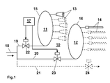
- the fuel distribution system 10 of the Fig. 1 includes a plurality of burner stages, of which the first two burner stages 11 and 12 are shown explicitly. Each of the burner stages comprises one or more burners 13 and 14, respectively, which are connected to a common fuel ring line 15 and 16, respectively.
- Each of the fuel ring lines 15, 16 is connected via a distribution line 19, 20, 21 to a common fuel supply 18, via which the fuel for the entire burner system is introduced.
- control valves 22, 23, 24 are arranged, which are connected to a controller 17, and are controlled by the controller 17 and regulated.
- the required fuel mass flow for the respective burner stage 11, 12 is set via the control valves 22, 23, 24.
- a fuel injection stage is usually designed at low load and the start of the gas turbine so that locally fuel-rich zones are set in the burner flow field, which ensure a wide operating field of the burner. In the higher load range, this fuel feed is significantly reduced in order to achieve low emission levels (see: EP-B1-0 704 657 and WO-A1-01 / 96785 ).
- the fuel supply set for the low load range should in this case preferably have the higher pressure drop with respect to the fuel feed, so that a sufficient fuel distribution over the burners can be ensured in full-load operation at low throughputs.
- a sufficiently small fuel mass flow must be set in order to avoid overfiring of the turbine. Since at the same time a plurality of control valves must be adjusted and regulated, it can lead to instabilities in the control behavior of the fuel feed, which can lead to increased pollutant emissions and pulsations in the combustion chamber.
- Essential for the invention is that in a part of the distribution lines as Element for selectively influencing the fuel mass flow in each case a control valve is arranged, and that in the other distribution lines as a member for selectively influencing the fuel mass flow in each case a fixed predetermined aperture is arranged.
- An embodiment of the invention is characterized in that only in one of the distribution lines, a control valve is arranged, and that the single control valve is arranged in the distribution line leading to the first burner stage. This makes it possible to achieve a particularly simple control.
- the diaphragms in the distribution lines are selected such that the respective fuel components of the individual burner stages are adjusted to a fuel ratio which is favorable for the load range of the gas turbine.
- control valve or the control valves are controlled by a controller.
- a further embodiment of the invention is characterized in that the burners of the individual combustion stages are each connected to a common fuel ring line, and that the fuel ring lines are each connected via one of the distribution lines with the common fuel supply.
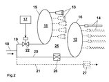
- Fig. 2 is in one too Fig. 1 comparable representation of a Brennstoffverteilsystem reproduced according to a preferred embodiment of the invention.
- the fuel distribution system 25 of the Fig. 2 includes a plurality of burner stages, of which the first two burner stages 11 and 12 are shown explicitly. Each of the burner stages comprises one or more burners 13 and 14, respectively, which are connected to a common fuel ring line 15 and 16, respectively.
- the burners 13 of the first stage can be in particular so-called double-cone burners, as for example from the EP-A2-1 645 802 (See eg the local there Fig. 1 ) are known.
- the burners 14 of the second stage can - as in the EP-A2-1 645 802 shown - designed as fuel lances and be arranged concentrically in the double-cone burners.
- Each of the fuel ring lines 15, 16 is connected via a distribution line 19, 20, 21 to a common fuel supply 18, via which the fuel for the entire burner system is introduced.
- the distribution lines 19, 20, 21 now different elements 22, 26, 27 are arranged for selectively influencing the fuel mass flow.
- a control valve 22 which is controlled or regulated by a controller 17.
- passive elements for selectively influencing the Fuel mass flow used namely fixed aperture 26, 27.
- only one check valve 22 is used to adjust the fuel mass flow for the primary stage.
- the adjustment of the mass flows for the individual burner stages is realized via permanently installed apertures 26, 27.
Landscapes
- Engineering & Computer Science (AREA)
- Chemical & Material Sciences (AREA)
- Combustion & Propulsion (AREA)
- Mechanical Engineering (AREA)
- General Engineering & Computer Science (AREA)
- Feeding And Controlling Fuel (AREA)
Abstract
Description
- Die vorliegende Erfindung bezieht sich auf das Gebiet der Gasturbinen. Sie betrifft ein Brennstoffverteilungssystem für eine Gasturbine mit mehrstufiger Brenneranordnung gemäss dem Oberbegriff des Anspruchs 1.
- Es ist bekannt (siehe z.B. die
WO-A1-2005/093327 ), bei Gasturbinen mit mehreren gleichzeitig in Betrieb befindlichen Brennerstufen eine Anspeisung der Brennerstufen mit Brennstoff über jeweils zwei oder mehrere geregelte Kontrollventile und Ringleitungen, je nach Anzahl der "Brennerstufungen", zu realisieren. Eine solche Anordnung ist in stark vereinfachter Form beispielhaft inFig. 1 wiedergegeben. Das Brennstoffverteilungssystem 10 derFig. 1 umfasst mehrere Brennerstufen, von denen die beiden ersten Brennerstufen 11 und 12 explizit dargestellt sind. Jede der Brennerstufen umfasst einen oder mehrere Brenner 13 bzw. 14, die an eine gemeinsame Brennstoffringleitung 15 bzw. 16 angeschlossen sind. Jede der Brennstoffringleitungen 15, 16 ist über eine Verteilleitung 19, 20, 21 an eine gemeinsame Brennstoffzuführung 18 angeschlossen, über die der Brennstoff für das gesamte Brennersystem herangeführt wird. In den Verteilleitungen 19, 20, 21 sind jeweils Kontrollventile 22, 23, 24 angeordnet, die an eine Steuerung 17 angeschlossen sind, und von der Steuerung 17 gesteuert bzw. geregelt werden. - Je nach Betriebspunkt wird über die Kontrollventile 22, 23, 24 der benötigte Brennstoffmassenstrom für die jeweilige Brennerstufe 11, 12 eingestellt. Hierbei wird normalerweise eine Brennstoffeinspeisungsstufe bei niedriger Last und beim Start der Gasturbine so ausgelegt, dass lokal im Brennerströmungsfeld brennstoffreiche Zonen eingestellt werden, die ein breites Betriebsfeld des Brenners gewährleisten. Im höheren Lastbereich wird diese Brennstoffeinspeisung deutlich reduziert, um niedrige Emissionswerte zu realisieren (siehe:
EP-B1-0 704 657 undWO-A1-01/96785 - Die für den niederen Lastbereich eingestellte Brennstoffeinspeisung soll hierbei vorzugsweise den höheren Druckverlust bezüglich der Brennstoffeinspeisung aufweisen, damit im Volllastbetrieb bei niedrigen Durchsätzen eine ausreichende Brennstoffverteilung über die Brenner gewährleistet werden kann. Andererseits muss bei der Zündung und beim Starten der Gasturbine ein ausreichend kleiner Brennstoffmassenstrom eingestellt werden, um ein Überfeuern der Turbine zu vermeiden. Da gleichzeitig eine Mehrzahl von Kontrollventilen eingestellt und geregelt werden muss, kann es zu Instabilitäten im Regelverhalten der Brennstoffeinspeisung kommen, die zu erhöhtem Schadstoffausstoss und Pulsationen in der Brennkammer führen können.
- Es ist daher Aufgabe der Erfindung, ein Brennstoffverteilsystem für Gasturbinen zu schaffen, welches die Nachteile bekannter Brennstoffverteilsysteme vermeidet und sich insbesondere durch die Möglichkeit für ein vereinfachtes Regelungsverfahren und einen schadstoffarmen und pulsationsfreien Betrieb auszeichnet.
- Die Aufgabe wird durch die Gesamtheit der Merkmale des Anspruchs 1 gelöst. Wesentlich für die Erfindung ist, dass in einem Teil der Verteilleitungen als Element zur gezielten Beeinflussung des Brennstoffmassenstroms jeweils ein Kontrollventil angeordnet ist, und dass in den übrigen Verteilleitungen als Element zur gezielten Beeinflussung des Brennstoffmassenstroms jeweils eine fest vorgegebene Blende angeordnet ist.
- Eine Ausgestaltung der Erfindung zeichnet sich dadurch aus, dass nur in einer der Verteilleitungen ein Kontrollventil angeordnet ist, und dass das einzige Kontrollventil in der zur ersten Brennerstufe führenden Verteilleitung angeordnet ist. Hierdurch lässt sich eine besonders einfache Regelung erzielen.
- Gemäss einer anderen Ausgestaltung der Erfindung sind die Blenden in den Verteilleitungen so gewählt, dass sich die jeweiligen Brennstoffanteile der einzelnen Brennerstufen auf ein für den Lastbereich der Gasturbine günstiges Brennstoffverhältnis einstellen.
- Bevorzugt werden das Kontrollventil bzw. die Kontrollventile von einer Steuerung gesteuert.
- Eine weitere Ausgestaltung der Erfindung ist dadurch gekennzeichnet, dass die Brenner der einzelnen Brennstufen jeweils an eine gemeinsame Brennstoffringleitung angeschlossen sind, und dass die Brennstoffringleitungen jeweils über eine der Verteilleitungen mit der gemeinsamen Brennstoffzuführung verbunden sind.
- Die Erfindung soll nachfolgend anhand von Ausführungsbeispielen im Zusammenhang mit der Zeichnung näher erläutert werden. Es zeigen
- Fig. 1
- ein stark vereinfachtes Schema eines Brennstoffverteilsystems mit Kontrollventilen in allen Verteilleitungen, wie es aus dem Stand der Technik bekannt ist; und
- Fig. 2
- in einer zu
Fig. 1 vergleichbaren Darstellung ein Brennstoffverteilsystem gemäss einem bevorzugten Ausführungsbeispiel der Erfindung. - In
Fig. 2 ist in einer zuFig. 1 vergleichbaren Darstellung ein Brennstoffverteilsystem gemäss einem bevorzugten Ausführungsbeispiel der Erfindung wiedergegeben. Auch das Brennstoffverteilsystem 25 derFig. 2 umfasst mehrere Brennerstufen, von denen die beiden ersten Brennerstufen 11 und 12 explizit dargestellt sind. Jede der Brennerstufen umfasst einen oder mehrere Brenner 13 bzw. 14, die an eine gemeinsame Brennstoffringleitung 15 bzw. 16 angeschlossen sind. Die Brenner 13 der ersten Stufe können dabei insbesondere sogenannte Doppelkegelbrenner sein, wie sie beispielsweise aus derEP-A2-1 645 802 (siehe z.B. die dortigeFig. 1 ) bekannt sind. Die Brenner 14 der zweiten Stufe können - wie in derEP-A2-1 645 802 gezeigt - als Brennstofflanzen ausgebildet und konzentrisch in den Doppelkegelbrennern angeordnet sein. Jede der Brennstoffringleitungen 15, 16 ist über eine Verteilleitung 19, 20, 21 an eine gemeinsame Brennstoffzuführung 18 angeschlossen, über die der Brennstoff für das gesamte Brennersystem herangeführt wird. In den Verteilleitungen 19, 20, 21 sind nun unterschiedliche Elemente 22, 26, 27 zur gezielten Beeinflussung des Brennstoffmassenstroms angeordnet. In der Verteilleitung 19 der ersten Stufe ist als Element zur gezielten Beeinflussung des Brennstoffmassenstroms wiederum ein Kontrollventil 22 eingesetzt, das von einer Steuerung 17 gesteuert bzw. geregelt wird. In den übrigen Verteilleitungen 20, 21 der weiteren Stufen sind dagegen passive Elemente zur gezielten Beeinflussung des Brennstoffmassenstroms eingesetzt, nämlich fest vorgegebene Blenden 26, 27. Bei der vorliegenden Erfindung gemässFig. 2 wird also, verglichen mit der herkömmlichen Lösung, nur ein Kontrollventil 22 zur Einstellung des Brennstoffmassenstroms für die Primärstufe benutzt. Die Einstellung der Massenströme für die einzelnen Brennerstufungen wird über fest installierte Blenden 26, 27 realisiert. - Entgegen der herkömmlichen Lösung muss hier nur noch der Brennstoffmassenstrom für die primäre Brennerstufe 11 geregelt werden, während sich die Massenströme der anderen Brennerstufe(n) 12 über den Vordruck und den Druckverlust über die Blenden 26, 27 in den sekundären Stufen ergeben. Daraus resultiert ein erheblich vereinfachtes Betriebskonzept der Anlage. Die jeweiligen Brennstoffanteile der einzelnen Stufen sollten sich, bei richtig dimensionierten Blenden 26, 27, auf ein für den Lastbereich günstiges Brennstoffverhältnis einstellen. Hierbei muss allerdings der Brenner im Hinblick auf Brennstoffstufungen ausgelegt sein.
- Durch die Einsparung eines Regelventils werden allfällige Instabilitäten im Regelverhalten der Brennstoffeinspeisung reduziert, da hier nur noch das Hauptventil 22 angesteuert werden muss und die anderen Massenströme sich automatisch anhand des Strömungswiderstandes, verursacht durch die Blende(n) 26, 27, einstellen.
- Dies bringt auch gewisse Vorteile bei einem plötzlichen Lastabwurf der Gasturbine. So kann hier signifikant schneller der Brennstoffmassenstrom kontrolliert reduziert werden, ohne dabei auf evtl. Regelventilschwankungen und Brennstoffstufungen für die einzelnen Betriebspunkte reagieren zu müssen, da sich diese automatisch einstellen.
- Mit der Erfindung lassen sich die folgenden charakteristischen Eigenschaften und Vorteile verbinden:
- Vereinfachtes Regelungsverfahren und Brennstoffversorgungssystem für eine Gasturbine im Öl- und Gasbetrieb.
- Anwendung für Gasturbinenbrenner mit gleichzeitig mehr als einer Brennstoffstufe in Betrieb.
- Schadstoffarmer und pulsationsfreier Betrieb bei der Verbrennung von flüssigen und gasförmigen Brennstoffen in einer Gasturbinenbrennkammer.
- Anwendung auf nasse und trockene Ölverbrennung.
- Kontrolle der CO- und NOx-Emissionen im gesamten Lastbereich.
- Anwendung für Ring-, Topfbüchsen-, Silo- und Rohrbrennkammern mit Einzel- bzw. Mehrfachbrenneranordnungen.
-
- 10,25
- Brennstoffverteilungssystem
- 11,12
- Brennerstufe
- 13,14
- Brenner
- 15,16
- Brennstoffringleitung
- 17
- Steuerung
- 18
- Brennstoffzuführung
- 19,20,21
- Verteilleitung
- 22,23,24
- Kontrollventil
- 26,27
- Blende
Claims (6)
- Brennstoffverteilungssystem (25) für eine Gasturbine mit mehrstufiger Brenneranordnung, bei welchem Brennstoffverteilungssystem (25) von einer gemeinsamen Brennstoffzuführung (18) jeweils wenigstens eine Verteilleitung (19, 20, 21) abzweigt und zu einer Brennerstufe (11, 12) führt, wobei in jeder Verteilleitung (19, 20, 21) wenigstens ein Element (22, 26, 27) zur gezielten Beeinflussung des Brennstoffmassenstroms vorgesehen ist, dadurch gekennzeichnet, dass in einem Teil (19) der Verteilleitungen (19, 20, 21) als Element zur gezielten Beeinflussung des Brennstoffmassenstroms jeweils ein Kontrollventil (22) angeordnet ist, und dass in den übrigen Verteilleitungen (20, 21) als Element zur gezielten Beeinflussung des Brennstoffmassenstroms jeweils eine fest vorgegebene Blende (26, 27) angeordnet ist.
- Brennstoffverteilungssystem nach Anspruch 1, dadurch gekennzeichnet, dass nur in einer der Verteilleitungen (19, 20, 21) ein Kontrollventil (22) angeordnet ist.
- Brennstoffverteilungssystem nach Anspruch 2, dadurch gekennzeichnet, dass das einzige Kontrollventil (22) in der zur ersten Brennerstufe (11) führenden Verteilleitung (19) angeordnet ist.
- Brennstoffverteilungssystem nach einem der Ansprüche 1 bis 3, dadurch gekennzeichnet, dass die Blenden (26, 27) in den Verteilleitungen so gewählt sind, dass sich die jeweiligen Brennstoffanteile der einzelnen Brennerstufen (11, 12) auf ein für den Lastbereich der Gasturbine günstiges Brennstoffverhältnis einstellen.
- Brennstoffverteilungssystem nach einem der Ansprüche 1 bis 4, dadurch gekennzeichnet, dass das Kontrollventil (22) bzw. die Kontrollventile von einer Steuerung (17) gesteuert werden.
- Brennstoffverteilungssystem nach einem der Ansprüche 1 bis 5, dadurch gekennzeichnet, dass die Brenner (13, 14) der einzelnen Brennstufen (11, 12) jeweils an eine gemeinsame Brennstoffringleitung (15, 16) angeschlossen sind, und dass die Brennstoffringleitungen (15, 16) jeweils über eine der Verteilleitungen (19, 20, 21) mit der gemeinsamen Brennstoffzuführung (18) verbunden ist.
Applications Claiming Priority (1)
| Application Number | Priority Date | Filing Date | Title |
|---|---|---|---|
| CH19182007 | 2007-12-10 |
Publications (2)
| Publication Number | Publication Date |
|---|---|
| EP2071156A1 true EP2071156A1 (de) | 2009-06-17 |
| EP2071156B1 EP2071156B1 (de) | 2013-11-06 |
Family
ID=39217949
Family Applications (1)
| Application Number | Title | Priority Date | Filing Date |
|---|---|---|---|
| EP08169482.0A Not-in-force EP2071156B1 (de) | 2007-12-10 | 2008-11-20 | Brennstoffverteilungssystem für eine Gasturbine mit mehrstufiger Brenneranordnung |
Country Status (2)
| Country | Link |
|---|---|
| US (1) | US8776524B2 (de) |
| EP (1) | EP2071156B1 (de) |
Families Citing this family (8)
| Publication number | Priority date | Publication date | Assignee | Title |
|---|---|---|---|---|
| US20140061327A1 (en) * | 2012-08-31 | 2014-03-06 | General Electric Company | System and method for staging fuel to a combustor |
| EP2857658A1 (de) * | 2013-10-01 | 2015-04-08 | Alstom Technology Ltd | Gasturbine mit einer sequentiellen Brennanordnung |
| US9863322B2 (en) | 2014-01-23 | 2018-01-09 | United Technologies Corporation | Selectively deoxygenated stored fuel system |
| US20160169120A1 (en) * | 2014-12-10 | 2016-06-16 | United Technologies Corporation | Fuel Schedule for Robust Gas Turbine Engine Transition Between Steady States |
| JP6651389B2 (ja) * | 2016-03-08 | 2020-02-19 | 三菱日立パワーシステムズ株式会社 | 燃料制御装置、燃焼器、ガスタービン、燃料制御方法及びプログラム |
| US11174792B2 (en) | 2019-05-21 | 2021-11-16 | General Electric Company | System and method for high frequency acoustic dampers with baffles |
| US11156164B2 (en) | 2019-05-21 | 2021-10-26 | General Electric Company | System and method for high frequency accoustic dampers with caps |
| DE102023207553A1 (de) * | 2023-08-07 | 2025-02-13 | Rolls-Royce Deutschland Ltd & Co Kg | Fluidzuführanordnung, insbesondere zur zuführung von kraftstoff aus einem kraftstoffspeicher zu einer brennkammer |
Citations (9)
| Publication number | Priority date | Publication date | Assignee | Title |
|---|---|---|---|---|
| GB2174147A (en) * | 1985-04-25 | 1986-10-29 | Rolls Royce | Improvements in or relating to gas turbine engine fuel systems |
| DE4240222A1 (de) * | 1991-11-29 | 1993-06-03 | Toshiba Kawasaki Kk | |
| EP0969192A1 (de) * | 1998-06-29 | 2000-01-05 | Asea Brown Boveri AG | Verfahren zum Abgleichen des Brennstoffverteilsystems bei Gasturbinen mit mehreren Brennern |
| EP1067338A2 (de) * | 1999-07-06 | 2001-01-10 | General Electric Company | Verfahren und Einrichtung zur Optimierung von NOx-Ausstoss in einer Gasturbine |
| EP0704657B1 (de) | 1994-10-01 | 2001-11-07 | ABB Alstom Power (Schweiz) AG | Brenner |
| WO2001096785A1 (de) | 2000-06-15 | 2001-12-20 | Alstom (Switzerland) Ltd | Verfahren zum betrieb eines brenners sowie brenner mit gestufter vormischgas-eindüsung |
| WO2005010437A1 (de) * | 2003-07-24 | 2005-02-03 | Alstom Technology Ltd | Verfahren zur reduktion der nox-emissionen einer mehrere brenner umfassenden brenneranordnung sowie brenneranordnung zur durchführung des verfahrens |
| WO2005093327A1 (de) | 2004-03-29 | 2005-10-06 | Alstom Technology Ltd | Brennkammer für eine gasturbine und zugehöriges betriebsverfahren |
| EP1645802A2 (de) | 2004-10-11 | 2006-04-12 | ALSTOM Technology Ltd | Vormischbrenner |
Family Cites Families (10)
| Publication number | Priority date | Publication date | Assignee | Title |
|---|---|---|---|---|
| US2944388A (en) * | 1955-02-24 | 1960-07-12 | Thompson Ramo Wooldridge Inc | Air atomizing spray bar |
| US2963862A (en) * | 1960-03-21 | 1960-12-13 | Orenda Engines Ltd | Fuel systems |
| GB1064367A (en) * | 1965-11-01 | 1967-04-05 | Rolls Royce | Burner device |
| US4920740A (en) * | 1987-11-23 | 1990-05-01 | Sundstrand Corporation | Starting of turbine engines |
| CH674561A5 (de) | 1987-12-21 | 1990-06-15 | Bbc Brown Boveri & Cie | |
| US6405524B1 (en) * | 2000-08-16 | 2002-06-18 | General Electric Company | Apparatus for decreasing gas turbine combustor emissions |
| DE60217768T2 (de) * | 2001-07-18 | 2007-11-15 | Rolls-Royce Plc | Kraftstofffördervorrichtung |
| US7269939B2 (en) * | 2004-11-24 | 2007-09-18 | General Electric Company | Method and apparatus for automatically actuating fuel trim valves in a gas |
| JP4119909B2 (ja) * | 2005-09-14 | 2008-07-16 | 三菱重工業株式会社 | ガスタービンの燃焼制御装置 |
| GB0708745D0 (en) * | 2007-05-04 | 2007-06-13 | Rolls Royce Plc | Fuel supply system |
-
2008
- 2008-11-20 EP EP08169482.0A patent/EP2071156B1/de not_active Not-in-force
- 2008-12-02 US US12/326,704 patent/US8776524B2/en active Active
Patent Citations (9)
| Publication number | Priority date | Publication date | Assignee | Title |
|---|---|---|---|---|
| GB2174147A (en) * | 1985-04-25 | 1986-10-29 | Rolls Royce | Improvements in or relating to gas turbine engine fuel systems |
| DE4240222A1 (de) * | 1991-11-29 | 1993-06-03 | Toshiba Kawasaki Kk | |
| EP0704657B1 (de) | 1994-10-01 | 2001-11-07 | ABB Alstom Power (Schweiz) AG | Brenner |
| EP0969192A1 (de) * | 1998-06-29 | 2000-01-05 | Asea Brown Boveri AG | Verfahren zum Abgleichen des Brennstoffverteilsystems bei Gasturbinen mit mehreren Brennern |
| EP1067338A2 (de) * | 1999-07-06 | 2001-01-10 | General Electric Company | Verfahren und Einrichtung zur Optimierung von NOx-Ausstoss in einer Gasturbine |
| WO2001096785A1 (de) | 2000-06-15 | 2001-12-20 | Alstom (Switzerland) Ltd | Verfahren zum betrieb eines brenners sowie brenner mit gestufter vormischgas-eindüsung |
| WO2005010437A1 (de) * | 2003-07-24 | 2005-02-03 | Alstom Technology Ltd | Verfahren zur reduktion der nox-emissionen einer mehrere brenner umfassenden brenneranordnung sowie brenneranordnung zur durchführung des verfahrens |
| WO2005093327A1 (de) | 2004-03-29 | 2005-10-06 | Alstom Technology Ltd | Brennkammer für eine gasturbine und zugehöriges betriebsverfahren |
| EP1645802A2 (de) | 2004-10-11 | 2006-04-12 | ALSTOM Technology Ltd | Vormischbrenner |
Also Published As
| Publication number | Publication date |
|---|---|
| US20090145131A1 (en) | 2009-06-11 |
| EP2071156B1 (de) | 2013-11-06 |
| US8776524B2 (en) | 2014-07-15 |
Similar Documents
| Publication | Publication Date | Title |
|---|---|---|
| EP2071156B1 (de) | Brennstoffverteilungssystem für eine Gasturbine mit mehrstufiger Brenneranordnung | |
| EP0697507B1 (de) | Verfahren und Anordnung zur Drehzahlregelung einer Gasturbine bei Lastabwurf | |
| DE69719588T2 (de) | Kraftstoffzufuhrsystem für eine Gasturbine | |
| EP1730449B1 (de) | Brennkammer für eine gasturbine und zugehöriges betriebsverfahren | |
| EP1205653B1 (de) | Brennersystem mit gestufter Brennstoff-Eindüsung und Verfahren zum Betrieb | |
| EP2414653B1 (de) | Gasturbine mit verbessertem teillast-emissionsverhalten | |
| EP1319895B1 (de) | Magervormischbrenner für eine Gasturbine sowie Verfahren zum Betrieb eines Magervormischbrenners | |
| EP1840465A2 (de) | Brennersystem mit gestufter Brennstoff-Eindüsung | |
| EP1730448B1 (de) | Mehrfachbrenneranordnung zum betrieb einer brennkammer sowie verfahren zum betreiben der mehrfachbrenneranordnung | |
| EP1621811A1 (de) | Betriebsverfahren für eine Feuerungsanlage | |
| WO2011023648A2 (de) | Drallschaufel, brenner und gasturbine | |
| DE102004027702A1 (de) | Injektor für Flüssigbrennstoff sowie gestufter Vormischbrenner mit diesem Injektor | |
| DE102020132494A1 (de) | Gasturbinenbrennkammersystem und Verfahren zum Betreiben eines Gasturbinenbrennkammersystems | |
| DE19545311B4 (de) | Verfahren zur Betrieb einer mit Vormischbrennern bestückten Brennkammer | |
| EP3250857B1 (de) | Brenneranordnung | |
| EP1649218B1 (de) | Verfahren zur reduktion der nox-emissionen einer mehrere brenner umfassenden brenneranordnung sowie brenneranordnung zur durchführung des verfahrens | |
| DE2906223A1 (de) | Brennstoffsteuerung fuer turbinen-nachbrenner | |
| EP3698031B1 (de) | Verfahren zum betreiben einer brenneranordnung, bevorzugterweise einer gasturbine | |
| DE102017120370A1 (de) | Brennerkopf, Brennersystem und Verfahren zum Betreiben des Brennersystems | |
| DE102005061486B4 (de) | Verfahren zum Betreiben einer Brennkammer einer Gasturbine | |
| EP3926238B1 (de) | Baugruppe einer gasturbine mit brennkammerluftbypass | |
| EP3628845B1 (de) | Verfahren zum betreiben einer gasturbinenanordnung und gasturbinenanordnung | |
| DE19825335A1 (de) | Verfahren zum Betrieb einer Gasturbine | |
| EP2778531A1 (de) | Gasturbine mit optimierter Verbrennung im Teillastbetrieb durch Luftmengenregelung | |
| DE19810750A1 (de) | Verfahren und Vorrichtung zum Betreiben eines atmosphärischen Gasbrenners |
Legal Events
| Date | Code | Title | Description |
|---|---|---|---|
| PUAI | Public reference made under article 153(3) epc to a published international application that has entered the european phase |
Free format text: ORIGINAL CODE: 0009012 |
|
| AK | Designated contracting states |
Kind code of ref document: A1 Designated state(s): AT BE BG CH CY CZ DE DK EE ES FI FR GB GR HR HU IE IS IT LI LT LU LV MC MT NL NO PL PT RO SE SI SK TR |
|
| AX | Request for extension of the european patent |
Extension state: AL BA MK RS |
|
| 17P | Request for examination filed |
Effective date: 20091207 |
|
| 17Q | First examination report despatched |
Effective date: 20100113 |
|
| AKX | Designation fees paid |
Designated state(s): AT BE BG CH CY CZ DE DK EE ES FI FR GB GR HR HU IE IS IT LI LT LU LV MC MT NL NO PL PT RO SE SI SK TR |
|
| GRAP | Despatch of communication of intention to grant a patent |
Free format text: ORIGINAL CODE: EPIDOSNIGR1 |
|
| INTG | Intention to grant announced |
Effective date: 20130611 |
|
| GRAS | Grant fee paid |
Free format text: ORIGINAL CODE: EPIDOSNIGR3 |
|
| GRAA | (expected) grant |
Free format text: ORIGINAL CODE: 0009210 |
|
| AK | Designated contracting states |
Kind code of ref document: B1 Designated state(s): AT BE BG CH CY CZ DE DK EE ES FI FR GB GR HR HU IE IS IT LI LT LU LV MC MT NL NO PL PT RO SE SI SK TR |
|
| REG | Reference to a national code |
Ref country code: GB Ref legal event code: FG4D Free format text: NOT ENGLISH |
|
| REG | Reference to a national code |
Ref country code: CH Ref legal event code: EP |
|
| REG | Reference to a national code |
Ref country code: AT Ref legal event code: REF Ref document number: 639660 Country of ref document: AT Kind code of ref document: T Effective date: 20131215 |
|
| REG | Reference to a national code |
Ref country code: IE Ref legal event code: FG4D Free format text: LANGUAGE OF EP DOCUMENT: GERMAN |
|
| REG | Reference to a national code |
Ref country code: DE Ref legal event code: R096 Ref document number: 502008010900 Country of ref document: DE Effective date: 20140102 |
|
| REG | Reference to a national code |
Ref country code: NL Ref legal event code: VDEP Effective date: 20131106 |
|
| REG | Reference to a national code |
Ref country code: LT Ref legal event code: MG4D |
|
| PG25 | Lapsed in a contracting state [announced via postgrant information from national office to epo] |
Ref country code: HR Free format text: LAPSE BECAUSE OF FAILURE TO SUBMIT A TRANSLATION OF THE DESCRIPTION OR TO PAY THE FEE WITHIN THE PRESCRIBED TIME-LIMIT Effective date: 20131106 Ref country code: SE Free format text: LAPSE BECAUSE OF FAILURE TO SUBMIT A TRANSLATION OF THE DESCRIPTION OR TO PAY THE FEE WITHIN THE PRESCRIBED TIME-LIMIT Effective date: 20131106 Ref country code: IS Free format text: LAPSE BECAUSE OF FAILURE TO SUBMIT A TRANSLATION OF THE DESCRIPTION OR TO PAY THE FEE WITHIN THE PRESCRIBED TIME-LIMIT Effective date: 20140306 Ref country code: FI Free format text: LAPSE BECAUSE OF FAILURE TO SUBMIT A TRANSLATION OF THE DESCRIPTION OR TO PAY THE FEE WITHIN THE PRESCRIBED TIME-LIMIT Effective date: 20131106 Ref country code: NL Free format text: LAPSE BECAUSE OF FAILURE TO SUBMIT A TRANSLATION OF THE DESCRIPTION OR TO PAY THE FEE WITHIN THE PRESCRIBED TIME-LIMIT Effective date: 20131106 Ref country code: LT Free format text: LAPSE BECAUSE OF FAILURE TO SUBMIT A TRANSLATION OF THE DESCRIPTION OR TO PAY THE FEE WITHIN THE PRESCRIBED TIME-LIMIT Effective date: 20131106 Ref country code: NO Free format text: LAPSE BECAUSE OF FAILURE TO SUBMIT A TRANSLATION OF THE DESCRIPTION OR TO PAY THE FEE WITHIN THE PRESCRIBED TIME-LIMIT Effective date: 20140206 |
|
| PG25 | Lapsed in a contracting state [announced via postgrant information from national office to epo] |
Ref country code: LV Free format text: LAPSE BECAUSE OF FAILURE TO SUBMIT A TRANSLATION OF THE DESCRIPTION OR TO PAY THE FEE WITHIN THE PRESCRIBED TIME-LIMIT Effective date: 20131106 Ref country code: ES Free format text: LAPSE BECAUSE OF FAILURE TO SUBMIT A TRANSLATION OF THE DESCRIPTION OR TO PAY THE FEE WITHIN THE PRESCRIBED TIME-LIMIT Effective date: 20131106 |
|
| BERE | Be: lapsed |
Owner name: ALSTOM TECHNOLOGY LTD Effective date: 20131130 |
|
| PG25 | Lapsed in a contracting state [announced via postgrant information from national office to epo] |
Ref country code: PT Free format text: LAPSE BECAUSE OF FAILURE TO SUBMIT A TRANSLATION OF THE DESCRIPTION OR TO PAY THE FEE WITHIN THE PRESCRIBED TIME-LIMIT Effective date: 20140306 |
|
| REG | Reference to a national code |
Ref country code: CH Ref legal event code: PL |
|
| PG25 | Lapsed in a contracting state [announced via postgrant information from national office to epo] |
Ref country code: CH Free format text: LAPSE BECAUSE OF NON-PAYMENT OF DUE FEES Effective date: 20131130 Ref country code: EE Free format text: LAPSE BECAUSE OF FAILURE TO SUBMIT A TRANSLATION OF THE DESCRIPTION OR TO PAY THE FEE WITHIN THE PRESCRIBED TIME-LIMIT Effective date: 20131106 Ref country code: LI Free format text: LAPSE BECAUSE OF NON-PAYMENT OF DUE FEES Effective date: 20131130 |
|
| REG | Reference to a national code |
Ref country code: DE Ref legal event code: R097 Ref document number: 502008010900 Country of ref document: DE |
|
| REG | Reference to a national code |
Ref country code: IE Ref legal event code: MM4A |
|
| PG25 | Lapsed in a contracting state [announced via postgrant information from national office to epo] |
Ref country code: CZ Free format text: LAPSE BECAUSE OF FAILURE TO SUBMIT A TRANSLATION OF THE DESCRIPTION OR TO PAY THE FEE WITHIN THE PRESCRIBED TIME-LIMIT Effective date: 20131106 Ref country code: RO Free format text: LAPSE BECAUSE OF FAILURE TO SUBMIT A TRANSLATION OF THE DESCRIPTION OR TO PAY THE FEE WITHIN THE PRESCRIBED TIME-LIMIT Effective date: 20131106 Ref country code: IT Free format text: LAPSE BECAUSE OF FAILURE TO SUBMIT A TRANSLATION OF THE DESCRIPTION OR TO PAY THE FEE WITHIN THE PRESCRIBED TIME-LIMIT Effective date: 20131106 Ref country code: MC Free format text: LAPSE BECAUSE OF FAILURE TO SUBMIT A TRANSLATION OF THE DESCRIPTION OR TO PAY THE FEE WITHIN THE PRESCRIBED TIME-LIMIT Effective date: 20131106 Ref country code: SK Free format text: LAPSE BECAUSE OF FAILURE TO SUBMIT A TRANSLATION OF THE DESCRIPTION OR TO PAY THE FEE WITHIN THE PRESCRIBED TIME-LIMIT Effective date: 20131106 Ref country code: PL Free format text: LAPSE BECAUSE OF FAILURE TO SUBMIT A TRANSLATION OF THE DESCRIPTION OR TO PAY THE FEE WITHIN THE PRESCRIBED TIME-LIMIT Effective date: 20131106 |
|
| PLBE | No opposition filed within time limit |
Free format text: ORIGINAL CODE: 0009261 |
|
| STAA | Information on the status of an ep patent application or granted ep patent |
Free format text: STATUS: NO OPPOSITION FILED WITHIN TIME LIMIT |
|
| PG25 | Lapsed in a contracting state [announced via postgrant information from national office to epo] |
Ref country code: BE Free format text: LAPSE BECAUSE OF NON-PAYMENT OF DUE FEES Effective date: 20131130 Ref country code: DK Free format text: LAPSE BECAUSE OF FAILURE TO SUBMIT A TRANSLATION OF THE DESCRIPTION OR TO PAY THE FEE WITHIN THE PRESCRIBED TIME-LIMIT Effective date: 20131106 |
|
| 26N | No opposition filed |
Effective date: 20140807 |
|
| REG | Reference to a national code |
Ref country code: FR Ref legal event code: ST Effective date: 20140917 |
|
| PG25 | Lapsed in a contracting state [announced via postgrant information from national office to epo] |
Ref country code: IE Free format text: LAPSE BECAUSE OF NON-PAYMENT OF DUE FEES Effective date: 20131120 |
|
| REG | Reference to a national code |
Ref country code: DE Ref legal event code: R097 Ref document number: 502008010900 Country of ref document: DE Effective date: 20140807 |
|
| PG25 | Lapsed in a contracting state [announced via postgrant information from national office to epo] |
Ref country code: FR Free format text: LAPSE BECAUSE OF NON-PAYMENT OF DUE FEES Effective date: 20140106 |
|
| REG | Reference to a national code |
Ref country code: AT Ref legal event code: MM01 Ref document number: 639660 Country of ref document: AT Kind code of ref document: T Effective date: 20131120 |
|
| PG25 | Lapsed in a contracting state [announced via postgrant information from national office to epo] |
Ref country code: AT Free format text: LAPSE BECAUSE OF NON-PAYMENT OF DUE FEES Effective date: 20131120 Ref country code: SI Free format text: LAPSE BECAUSE OF FAILURE TO SUBMIT A TRANSLATION OF THE DESCRIPTION OR TO PAY THE FEE WITHIN THE PRESCRIBED TIME-LIMIT Effective date: 20131106 |
|
| PG25 | Lapsed in a contracting state [announced via postgrant information from national office to epo] |
Ref country code: CY Free format text: LAPSE BECAUSE OF FAILURE TO SUBMIT A TRANSLATION OF THE DESCRIPTION OR TO PAY THE FEE WITHIN THE PRESCRIBED TIME-LIMIT Effective date: 20131106 Ref country code: TR Free format text: LAPSE BECAUSE OF FAILURE TO SUBMIT A TRANSLATION OF THE DESCRIPTION OR TO PAY THE FEE WITHIN THE PRESCRIBED TIME-LIMIT Effective date: 20131106 |
|
| PG25 | Lapsed in a contracting state [announced via postgrant information from national office to epo] |
Ref country code: BG Free format text: LAPSE BECAUSE OF FAILURE TO SUBMIT A TRANSLATION OF THE DESCRIPTION OR TO PAY THE FEE WITHIN THE PRESCRIBED TIME-LIMIT Effective date: 20131106 Ref country code: HU Free format text: LAPSE BECAUSE OF FAILURE TO SUBMIT A TRANSLATION OF THE DESCRIPTION OR TO PAY THE FEE WITHIN THE PRESCRIBED TIME-LIMIT; INVALID AB INITIO Effective date: 20081120 Ref country code: LU Free format text: LAPSE BECAUSE OF NON-PAYMENT OF DUE FEES Effective date: 20131120 |
|
| PG25 | Lapsed in a contracting state [announced via postgrant information from national office to epo] |
Ref country code: MT Free format text: LAPSE BECAUSE OF FAILURE TO SUBMIT A TRANSLATION OF THE DESCRIPTION OR TO PAY THE FEE WITHIN THE PRESCRIBED TIME-LIMIT Effective date: 20131106 Ref country code: GR Free format text: LAPSE BECAUSE OF NON-PAYMENT OF DUE FEES Effective date: 20131106 |
|
| PG25 | Lapsed in a contracting state [announced via postgrant information from national office to epo] |
Ref country code: GR Free format text: LAPSE BECAUSE OF FAILURE TO SUBMIT A TRANSLATION OF THE DESCRIPTION OR TO PAY THE FEE WITHIN THE PRESCRIBED TIME-LIMIT Effective date: 20140207 |
|
| REG | Reference to a national code |
Ref country code: DE Ref legal event code: R081 Ref document number: 502008010900 Country of ref document: DE Owner name: GENERAL ELECTRIC TECHNOLOGY GMBH, CH Free format text: FORMER OWNER: ALSTOM TECHNOLOGY LTD., BADEN, CH Ref country code: DE Ref legal event code: R081 Ref document number: 502008010900 Country of ref document: DE Owner name: ANSALDO ENERGIA SWITZERLAND AG, CH Free format text: FORMER OWNER: ALSTOM TECHNOLOGY LTD., BADEN, CH |
|
| REG | Reference to a national code |
Ref country code: GB Ref legal event code: 732E Free format text: REGISTERED BETWEEN 20170727 AND 20170802 |
|
| REG | Reference to a national code |
Ref country code: DE Ref legal event code: R081 Ref document number: 502008010900 Country of ref document: DE Owner name: ANSALDO ENERGIA SWITZERLAND AG, CH Free format text: FORMER OWNER: GENERAL ELECTRIC TECHNOLOGY GMBH, BADEN, CH |
|
| PGFP | Annual fee paid to national office [announced via postgrant information from national office to epo] |
Ref country code: DE Payment date: 20240130 Year of fee payment: 16 Ref country code: GB Payment date: 20240130 Year of fee payment: 16 |
|
| P01 | Opt-out of the competence of the unified patent court (upc) registered |
Effective date: 20240430 |
|
| REG | Reference to a national code |
Ref country code: DE Ref legal event code: R119 Ref document number: 502008010900 Country of ref document: DE |
|
| GBPC | Gb: european patent ceased through non-payment of renewal fee |
Effective date: 20241120 |
|
| PG25 | Lapsed in a contracting state [announced via postgrant information from national office to epo] |
Ref country code: DE Free format text: LAPSE BECAUSE OF NON-PAYMENT OF DUE FEES Effective date: 20250603 |
|
| PG25 | Lapsed in a contracting state [announced via postgrant information from national office to epo] |
Ref country code: GB Free format text: LAPSE BECAUSE OF NON-PAYMENT OF DUE FEES Effective date: 20241120 |