EP2071148A2 - Tappet clearance adjusting cover coupled with secondary air valve - Google Patents
Tappet clearance adjusting cover coupled with secondary air valve Download PDFInfo
- Publication number
- EP2071148A2 EP2071148A2 EP08019178A EP08019178A EP2071148A2 EP 2071148 A2 EP2071148 A2 EP 2071148A2 EP 08019178 A EP08019178 A EP 08019178A EP 08019178 A EP08019178 A EP 08019178A EP 2071148 A2 EP2071148 A2 EP 2071148A2
- Authority
- EP
- European Patent Office
- Prior art keywords
- secondary air
- clearance adjusting
- air valve
- tappet clearance
- adjusting cover
- Prior art date
- Legal status (The legal status is an assumption and is not a legal conclusion. Google has not performed a legal analysis and makes no representation as to the accuracy of the status listed.)
- Granted
Links
Images


Classifications
-
- F—MECHANICAL ENGINEERING; LIGHTING; HEATING; WEAPONS; BLASTING
- F01—MACHINES OR ENGINES IN GENERAL; ENGINE PLANTS IN GENERAL; STEAM ENGINES
- F01L—CYCLICALLY OPERATING VALVES FOR MACHINES OR ENGINES
- F01L1/00—Valve-gear or valve arrangements, e.g. lift-valve gear
- F01L1/46—Component parts, details, or accessories, not provided for in preceding subgroups
-
- F—MECHANICAL ENGINEERING; LIGHTING; HEATING; WEAPONS; BLASTING
- F01—MACHINES OR ENGINES IN GENERAL; ENGINE PLANTS IN GENERAL; STEAM ENGINES
- F01L—CYCLICALLY OPERATING VALVES FOR MACHINES OR ENGINES
- F01L3/00—Lift-valve, i.e. cut-off apparatus with closure members having at least a component of their opening and closing motion perpendicular to the closing faces; Parts or accessories thereof
- F01L3/20—Shapes or constructions of valve members, not provided for in preceding subgroups of this group
-
- F—MECHANICAL ENGINEERING; LIGHTING; HEATING; WEAPONS; BLASTING
- F01—MACHINES OR ENGINES IN GENERAL; ENGINE PLANTS IN GENERAL; STEAM ENGINES
- F01N—GAS-FLOW SILENCERS OR EXHAUST APPARATUS FOR MACHINES OR ENGINES IN GENERAL; GAS-FLOW SILENCERS OR EXHAUST APPARATUS FOR INTERNAL COMBUSTION ENGINES
- F01N3/00—Exhaust or silencing apparatus having means for purifying, rendering innocuous, or otherwise treating exhaust
- F01N3/08—Exhaust or silencing apparatus having means for purifying, rendering innocuous, or otherwise treating exhaust for rendering innocuous
- F01N3/10—Exhaust or silencing apparatus having means for purifying, rendering innocuous, or otherwise treating exhaust for rendering innocuous by thermal or catalytic conversion of noxious components of exhaust
- F01N3/24—Exhaust or silencing apparatus having means for purifying, rendering innocuous, or otherwise treating exhaust for rendering innocuous by thermal or catalytic conversion of noxious components of exhaust characterised by constructional aspects of converting apparatus
- F01N3/30—Arrangements for supply of additional air
- F01N3/34—Arrangements for supply of additional air using air conduits or jet air pumps, e.g. near the engine exhaust port
-
- Y—GENERAL TAGGING OF NEW TECHNOLOGICAL DEVELOPMENTS; GENERAL TAGGING OF CROSS-SECTIONAL TECHNOLOGIES SPANNING OVER SEVERAL SECTIONS OF THE IPC; TECHNICAL SUBJECTS COVERED BY FORMER USPC CROSS-REFERENCE ART COLLECTIONS [XRACs] AND DIGESTS
- Y02—TECHNOLOGIES OR APPLICATIONS FOR MITIGATION OR ADAPTATION AGAINST CLIMATE CHANGE
- Y02T—CLIMATE CHANGE MITIGATION TECHNOLOGIES RELATED TO TRANSPORTATION
- Y02T10/00—Road transport of goods or passengers
- Y02T10/10—Internal combustion engine [ICE] based vehicles
- Y02T10/12—Improving ICE efficiencies
Definitions
- the present invention relates to a secondary air valve of an engine, and more particularly to a tappet clearance adjusting cover coupled with a secondary air valve, so as to protect a one-way valve of the secondary air valve from premature deterioration and carbon deposition caused by a high-temperature exhaust gas from a cylinder head, and then increase the reliability and service life of the one-way valve and the flexibility and degree of freedom in designing the structure and space inside the cylinder.
- a first conventional secondary air valve of an engine is disposed in a main body 10 of a cylinder head of the engine.
- the main body 10 is provided with a combustion chamber 101 beneath and an exhaust duct 102 beneath.
- the exhaust duct 102 has one end communicating with the combustion chamber 101 for discharging an exhaust gas from the combustion chamber 101.
- the main body 10 has a top provided with a groove 103 while the secondary air valve is fixedly installed above the groove 103.
- the secondary air valve includes an inlet pipe 11 having an end formed with a pipe opening 111 in communication with the groove 103.
- a one-way valve 12 including a valve member 121 and a valve opening 122 is installed between the pipe opening 111 and the groove 103 to separate the pipe opening 111 from the groove 103 and form two totally independent spaces.
- the main body 10 is internally provided with an air duct 13 configured for communication between the groove 103 and the exhaust duct 102.
- the air duct 13 is composed of a transverse channel 104, a vertical channel 105 and a slanted channel 106 that communicate with one another.
- the transverse channel 104 is formed by boring and processing the main body 10 and inserting a blind plug 14 into a bore thus made.
- the vertical and slanted channels 105 and 106 are formed by boring and processing the main body 10 and inserting blind plugs 15 and 16 into corresponding bores thus made. Therefore, the one-way valve 12 is opened toward the exhaust duct 102 only when a suction force sufficient to open the valve member 121 of the one-way valve 12 toward the exhaust duct 102 is generated in the exhaust duct 102.
- the one-way valve 12 thus opened also introduces a secondary air into the exhaust duct 102 through the pipe opening 111 of the inlet pipe 11 and prevents the exhaust gas in the combustion chamber 101 from flowing back into the inlet pipe 11.
- the first conventional secondary air valve described above has the following defects:
- a second conventional secondary air valve of an engine includes a secondary inlet valve 3 installed on a plane 23 of a main body 2 of a cylinder head of the engine.
- the secondary inlet valve 3 includes a valve seat 31, an upper cover 32 and a one-way valve 33.
- the valve seat 31 is provided with a partition plate 312 for dividing an internal space of the secondary inlet valve 3 into a backflow chamber 311 and a valve member chamber 313.
- the partition plate 312 is formed with a communication hole 3121 to allow communication between the backflow chamber 311 and the valve member chamber 313.
- the one-way valve 33 is received in the valve member chamber 313 and covered by the upper cover 32.
- the valve seat 31 and the upper cover 32 are secured on the plane 23 of the main body 2 with bolts.
- the upper cover 32 has a top in communication with an end of a secondary air inlet pipe 22.
- the main body 2 is provided internally with an air duct 21, whose two ends are connected respectively with the backflow chamber 311 and an exhaust duct 24 in the main body 2.
- Ambient air entering the secondary air inlet pipe 22 flows sequentially through the upper cover 32, the one-way valve 33, the communication hole 3121, the backflow chamber 311 and the air duct 21, before being discharged via the exhaust duct 24.
- carbon contained therein will be blocked by the partition plate 312 and retained inside the backflow chamber 311.
- the second conventional secondary air valve described above though capable of reducing backflow of the exhaust gas and thereby preventing failure of the one-way valve 33 due to carbon deposition, is disadvantaged by structural complexity of the valve seat 31.
- the plane 23 through which the valve seat 31 contacts the main body 2 of the cylinder head demands high flatness and high-precision processing, thereby not only raising the difficulty in processing, but also significantly increasing the production cost of the main body 2 and the valve seat 31.
- the valve seat 31 since the valve seat 31 must be divided into the backflow chamber 311 and the valve member chamber 313, and the valve seat 31 must be secured tightly on the main body 2, the degree of freedom in structural design of the valve seat 31 and the main body 2 of the cylinder head is greatly restricted.
- the inventor of the present invention after making continuous efforts in relevant research, finally succeeded in developing a tappet clearance adjusting cover coupled with a secondary air valve as disclosed herein, with the aim of effectively solving the carbon deposition and premature aging problems of the one-way valves in the aforesaid conventional secondary air valves on the cylinder heads, so as to improve the reliability and service life of the one-way valves.
- An objective of the present invention is to provide a tappet clearance adjusting cover coupled with a secondary air valve, wherein the tappet clearance adjusting cover is disposed on a tappet clearance adjusting hole of a cylinder head and connected with the secondary air valve.
- the secondary air valve includes a recessed element and a cap which jointly form a receiving space receiving therein a one-way valve.
- the recessed element is located below the one-way valve and provided with an inlet pipe interposed between the cap and the tappet clearance adjusting cover.
- Another objective of the present invention is to provide a tappet clearance adjusting cover coupled with a secondary air valve, wherein a one-way valve does not occupy any internal space of a cylinder head so that a structure and space inside the cylinder head can be designed with increased flexibility and a high degree of freedom while a structure of the cylinder head is significantly simplified.
- the complicated processing procedures required by the air duct and valve seat of the conventional cylinder head can be avoided to effectively improve the degree of freedom in design.
- Yet another objective of the present invention is to provide a tappet clearance adjusting cover coupled with a secondary air valve, wherein the tappet clearance adjusting cover, together with the secondary air valve, is located on an exhaust side of the cylinder head, so as to avoid an otherwise excessively long exhaust pipe, thereby lowering the production cost effectively.
- a secondary air valve 4 is installed on a tappet clearance adjusting cover 51 outside a cylinder head 5 of an engine.
- a top of the cylinder head 5 has an inlet side and an exhaust side, each provided with a tappet clearance adjusting hole 50, wherein the tappet clearance adjusting cover 51 coupled with the secondary air valve 4 is disposed on and completely covers the tappet clearance adjusting hole 50 on the exhaust side of the cylinder head 5.
- the cap 43 and the recessed element 42 jointly form a receiving space therebetween.
- the recessed element 42 has one side protrudingly provided with an inlet pipe 45.
- the inlet pipe 45 is interposed between the cap 43 and the tappet clearance adjusting cover 51.
- the inlet pipe 45 has one end in communication with the receiving space and the other end connected with an external air inlet hose (not shown) for introducing a secondary air.
- the cap 43 has a top surface formed with an exhaust hole 431.
- An exhaust pipe 44 has one end connected with the exhaust hole 431 and the other end extended to and connected with the cylinder head 5, thereby guiding the secondary air into an exhaust duct (not shown).
- a one-way valve 46 provided in the secondary air valve 4 divides the receiving space into two completely independent spaces and interrupts a passage formed within the secondary air valve 4 between a pipe opening of the inlet pipe 45 and the exhaust hole 431. Only when a negative pressure sufficient to open the one-way valve 46 toward a predetermined single direction is generated in the exhaust pipe 44 will the one-way valve 46 be opened toward the exhaust hole 431, thereby allowing the secondary air to flow sequentially through the inlet pipe 45, the secondary air valve 4 and the exhaust pipe 44 before entering the exhaust duct of the cylinder head 5. Consequently, oxygen contained in an exhaust gas in the exhaust duct can be increased, so that incompletely oxidized pollutants in the exhaust gas can be oxidized again by virtue of a high temperature of the exhaust gas, thereby reducing the pollutants in the exhaust gas.
- the tappet clearance adjusting cover 51 has a top surface provided with a plurality of fastening posts 512, each having a top surface formed with a threaded hole 5121.
- the tappet clearance adjusting cover 51 is provided with a plurality of assembly holes 511, through which bolts (not shown) can pass to secure the tappet clearance adjusting cover 51 on the cylinder head 5 (as shown in Fig. 3 ).
- the recessed element 42 has a bottom surface formed with legs 422 corresponding in position to the fastening posts 512, respectively, wherein each of the legs 422 has a bottom surface provided with an assembly hole 4221 corresponding in position to a matching one of threaded holes 5121.
- the cap 43 has a bottom surface also formed with assembly holes 432 corresponding in position to the assembly holes 4221 of the recessed element 42, respectively.
- the two ends of the exhaust pipe 44 are provided with flanges 441 and 442, respectively, wherein the flanges 441 and 442 are formed with assembly holes 4411 and 4421, respectively.
- the two assembly holes 4411 on the flange 441 that is adjacent to the cap 43 correspond in position to the two assembly holes 432 on the cap 43.
- the secondary air valve 4 can be installed in the following way. First, the one-way valve 46 is placed between the recessed element 42 and the cap 43. Following that, securing elements such as bolts 52 are passed sequentially through the assembly holes 4411, the assembly holes 432 and the assembly holes 4221, and then secured in the threaded holes 5121. Next, another set of bolts (not shown) are passed through the assembly holes 4421 to secure the flange 442 at the other end of the exhaust pipe 44 to the cylinder head 5 (as shown in Fig. 3 ), thereby completing the installation of the secondary air valve 4 on the tappet clearance adjusting cover 51 of the cylinder head 5.
- the secondary air valve 4 is located outside the cylinder head 5 and away from the exhaust duct in the cylinder head 5. Therefore, compared with the prior art, not only is heat dissipation more efficient, but also the one-way valve 46 is far less likely to be affected by the high-temperature exhaust gas from the cylinder head 5, thereby effectively protecting the one-way valve 46 against premature aging and carbon deposition. In consequence, the one-way valve 46 can have a longer service life to make the resultant engine product more reliable and reduce customer complaints. Furthermore, the one-way valve 46 can be repaired and replaced without having to disassemble the cylinder head 5, thereby saving a lot of time and labor in the maintenance work.
- the cylinder head 5 can have its structure simplified and its production cost lowered.
- all that needs to be done is to modify the design of the tappet clearance adjusting cover 51 to allow installation of the secondary air valve 4.
- the degree of freedom in design is also enhanced.
- the tappet clearance adjusting cover coupled with the secondary air valve according to the present invention has the following advantages:
Abstract
Description
- The present invention relates to a secondary air valve of an engine, and more particularly to a tappet clearance adjusting cover coupled with a secondary air valve, so as to protect a one-way valve of the secondary air valve from premature deterioration and carbon deposition caused by a high-temperature exhaust gas from a cylinder head, and then increase the reliability and service life of the one-way valve and the flexibility and degree of freedom in designing the structure and space inside the cylinder.
- Referring to
Fig. 1 , a first conventional secondary air valve of an engine is disposed in amain body 10 of a cylinder head of the engine. Themain body 10 is provided with acombustion chamber 101 beneath and anexhaust duct 102 beneath. Theexhaust duct 102 has one end communicating with thecombustion chamber 101 for discharging an exhaust gas from thecombustion chamber 101. Themain body 10 has a top provided with agroove 103 while the secondary air valve is fixedly installed above thegroove 103. The secondary air valve includes aninlet pipe 11 having an end formed with a pipe opening 111 in communication with thegroove 103. A one-way valve 12 including avalve member 121 and avalve opening 122 is installed between thepipe opening 111 and thegroove 103 to separate thepipe opening 111 from thegroove 103 and form two totally independent spaces. In addition, themain body 10 is internally provided with anair duct 13 configured for communication between thegroove 103 and theexhaust duct 102. Theair duct 13 is composed of atransverse channel 104, avertical channel 105 and aslanted channel 106 that communicate with one another. Thetransverse channel 104 is formed by boring and processing themain body 10 and inserting ablind plug 14 into a bore thus made. Similarly, the vertical andslanted channels main body 10 and insertingblind plugs way valve 12 is opened toward theexhaust duct 102 only when a suction force sufficient to open thevalve member 121 of the one-way valve 12 toward theexhaust duct 102 is generated in theexhaust duct 102. The one-way valve 12 thus opened also introduces a secondary air into theexhaust duct 102 through the pipe opening 111 of theinlet pipe 11 and prevents the exhaust gas in thecombustion chamber 101 from flowing back into theinlet pipe 11. Hence, when the secondary air is introduced into theexhaust duct 102 through theinlet pipe 11 and theair duct 13, oxygen in the secondary air is mixed with the exhaust gas. As a result, pollutants in the exhaust gas that have not been completely burnt undergo a further, secondary combustion by virtue of a high temperature of the exhaust gas and with the assistance of the oxygen, thereby reducing the pollutants in the exhaust gas. - However, the first conventional secondary air valve described above has the following defects:
- (1) Since the
air duct 13 is provided inside themain body 10 and communicates directly with the one-way valve 12, which is spaced from theexhaust duct 102 only by a very short distance, the one-way valve 12 tends to age and deteriorate prematurely due to the high temperature of the exhaust gas released immediately after combustion. This aging and deteriorating process is aggravated by the fact that the exhaust gas is rich in carbon and confined within walls of themain body 10 that prevent easy heat dissipation. Moreover, the carbon in the exhaust gas flowing back tends to deposit between the openedvalve member 121 and the valve opening 122 so that thevalve member 121 becomes stuck and cannot work properly. - (2) The
air duct 13, which is composed of thetransverse channel 104, thevertical channel 105 and theslanted channel 106, takes up much space in themain body 10 of the cylinder head of the engine and thereby substantially lower the degree of freedom in designing the internal space and structure of themain body 10. Furthermore, theair duct 13 requires a complicated processing procedure that raises the processing and production costs of the cylinder head. - Referring to
Fig. 2 , a second conventional secondary air valve of an engine includes asecondary inlet valve 3 installed on aplane 23 of amain body 2 of a cylinder head of the engine. Thesecondary inlet valve 3 includes avalve seat 31, anupper cover 32 and a one-way valve 33. Thevalve seat 31 is provided with apartition plate 312 for dividing an internal space of thesecondary inlet valve 3 into abackflow chamber 311 and avalve member chamber 313. Thepartition plate 312 is formed with acommunication hole 3121 to allow communication between thebackflow chamber 311 and thevalve member chamber 313. The one-way valve 33 is received in thevalve member chamber 313 and covered by theupper cover 32. Thevalve seat 31 and theupper cover 32 are secured on theplane 23 of themain body 2 with bolts. Theupper cover 32 has a top in communication with an end of a secondaryair inlet pipe 22. In addition, themain body 2 is provided internally with anair duct 21, whose two ends are connected respectively with thebackflow chamber 311 and anexhaust duct 24 in themain body 2. Ambient air entering the secondaryair inlet pipe 22 flows sequentially through theupper cover 32, the one-way valve 33, thecommunication hole 3121, thebackflow chamber 311 and theair duct 21, before being discharged via theexhaust duct 24. When an exhaust gas flows back, carbon contained therein will be blocked by thepartition plate 312 and retained inside thebackflow chamber 311. - The second conventional secondary air valve described above, though capable of reducing backflow of the exhaust gas and thereby preventing failure of the one-
way valve 33 due to carbon deposition, is disadvantaged by structural complexity of thevalve seat 31. Moreover, theplane 23 through which thevalve seat 31 contacts themain body 2 of the cylinder head demands high flatness and high-precision processing, thereby not only raising the difficulty in processing, but also significantly increasing the production cost of themain body 2 and thevalve seat 31. In addition, since thevalve seat 31 must be divided into thebackflow chamber 311 and thevalve member chamber 313, and thevalve seat 31 must be secured tightly on themain body 2, the degree of freedom in structural design of thevalve seat 31 and themain body 2 of the cylinder head is greatly restricted. - Therefore, engine manufacturers of today have endeavored to design a secondary air valve of an engine wherein a one-way valve of the secondary air valve will not experience carbon deposition and premature aging caused by a backflow of a high-temperature exhaust gas from a cylinder head of the engine. It is desired to improve the reliability and service life of the secondary air valve while maintaining a high degree of freedom in designing the cylinder head.
- In view of the shortcomings of the abovementioned secondary air valve structures, the inventor of the present invention, after making continuous efforts in relevant research, finally succeeded in developing a tappet clearance adjusting cover coupled with a secondary air valve as disclosed herein, with the aim of effectively solving the carbon deposition and premature aging problems of the one-way valves in the aforesaid conventional secondary air valves on the cylinder heads, so as to improve the reliability and service life of the one-way valves.
- An objective of the present invention is to provide a tappet clearance adjusting cover coupled with a secondary air valve, wherein the tappet clearance adjusting cover is disposed on a tappet clearance adjusting hole of a cylinder head and connected with the secondary air valve. The secondary air valve includes a recessed element and a cap which jointly form a receiving space receiving therein a one-way valve. The recessed element is located below the one-way valve and provided with an inlet pipe interposed between the cap and the tappet clearance adjusting cover. By disposing the secondary air valve on the tappet clearance adjusting cover and arranging the inlet pipe between the cap and the tappet clearance adjusting cover, with the one-way valve received in the receiving space of the secondary air valve rather than inside the cylinder head, heat dissipation can be improved while the one-way valve is protected effectively against premature deterioration and carbon deposition caused by a high-temperature exhaust gas from the cylinder head. Thus, reliability as well as a service life of the one-way valve is effectively increased.
- Another objective of the present invention is to provide a tappet clearance adjusting cover coupled with a secondary air valve, wherein a one-way valve does not occupy any internal space of a cylinder head so that a structure and space inside the cylinder head can be designed with increased flexibility and a high degree of freedom while a structure of the cylinder head is significantly simplified. In addition, the complicated processing procedures required by the air duct and valve seat of the conventional cylinder head can be avoided to effectively improve the degree of freedom in design.
- Yet another objective of the present invention is to provide a tappet clearance adjusting cover coupled with a secondary air valve, wherein the tappet clearance adjusting cover, together with the secondary air valve, is located on an exhaust side of the cylinder head, so as to avoid an otherwise excessively long exhaust pipe, thereby lowering the production cost effectively.
- The invention as well as a preferred mode of use, further objectives and advantages thereof will be best understood by referring to the following detailed description of an illustrative embodiment in conjunction with the accompanying drawings, wherein:
-
Fig. 1 is a schematic structural drawing showing a first conventional secondary air valve on a cylinder head; -
Fig. 2 is a schematic structural drawing showing a second conventional secondary air valve on a cylinder head; -
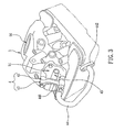
Fig. 3 is a schematic drawing showing a secondary air valve installed on a tappet clearance adjusting cover according to the present invention; -
Fig. 4 is a schematic exploded view of the tappet clearance adjusting cover coupled with the secondary air valve according to the present invention; -
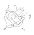
Fig. 5 is a schematic drawing showing a recessed element of the secondary air valve according to the present invention; and -
Fig. 6 is a schematic drawing showing a cap of the secondary air valve according to the present invention. - Referring to
Figs. 3 and4 , according to a preferred embodiment of the present invention, asecondary air valve 4 is installed on a tappetclearance adjusting cover 51 outside a cylinder head 5 of an engine. A top of the cylinder head 5 has an inlet side and an exhaust side, each provided with a tappetclearance adjusting hole 50, wherein the tappetclearance adjusting cover 51 coupled with thesecondary air valve 4 is disposed on and completely covers the tappetclearance adjusting hole 50 on the exhaust side of the cylinder head 5. Thesecondary air valve 4, which is composed of acap 43 and arecessed element 42, is located and secured on the tappetclearance adjusting cover 51 outside the cylinder head 5. Thecap 43 and therecessed element 42 jointly form a receiving space therebetween. Therecessed element 42 has one side protrudingly provided with aninlet pipe 45. Theinlet pipe 45 is interposed between thecap 43 and the tappetclearance adjusting cover 51. Theinlet pipe 45 has one end in communication with the receiving space and the other end connected with an external air inlet hose (not shown) for introducing a secondary air. Further, thecap 43 has a top surface formed with anexhaust hole 431. Anexhaust pipe 44 has one end connected with theexhaust hole 431 and the other end extended to and connected with the cylinder head 5, thereby guiding the secondary air into an exhaust duct (not shown). A one-way valve 46 provided in thesecondary air valve 4 divides the receiving space into two completely independent spaces and interrupts a passage formed within thesecondary air valve 4 between a pipe opening of theinlet pipe 45 and theexhaust hole 431. Only when a negative pressure sufficient to open the one-way valve 46 toward a predetermined single direction is generated in theexhaust pipe 44 will the one-way valve 46 be opened toward theexhaust hole 431, thereby allowing the secondary air to flow sequentially through theinlet pipe 45, thesecondary air valve 4 and theexhaust pipe 44 before entering the exhaust duct of the cylinder head 5. Consequently, oxygen contained in an exhaust gas in the exhaust duct can be increased, so that incompletely oxidized pollutants in the exhaust gas can be oxidized again by virtue of a high temperature of the exhaust gas, thereby reducing the pollutants in the exhaust gas. - In the foregoing embodiment, referring again to
Fig. 4 , the tappetclearance adjusting cover 51 has a top surface provided with a plurality offastening posts 512, each having a top surface formed with a threadedhole 5121. In addition, the tappetclearance adjusting cover 51 is provided with a plurality of assembly holes 511, through which bolts (not shown) can pass to secure the tappetclearance adjusting cover 51 on the cylinder head 5 (as shown inFig. 3 ). Referring now toFig. 5 , the recessedelement 42 has a bottom surface formed withlegs 422 corresponding in position to the fastening posts 512, respectively, wherein each of thelegs 422 has a bottom surface provided with anassembly hole 4221 corresponding in position to a matching one of threadedholes 5121. Referring toFig. 6 , thecap 43 has a bottom surface also formed withassembly holes 432 corresponding in position to the assembly holes 4221 of the recessedelement 42, respectively. As shown inFig. 4 , the two ends of theexhaust pipe 44 are provided withflanges flanges assembly holes assembly holes 4411 on theflange 441 that is adjacent to thecap 43 correspond in position to the twoassembly holes 432 on thecap 43. Thus, thesecondary air valve 4 can be installed in the following way. First, the one-way valve 46 is placed between the recessedelement 42 and thecap 43. Following that, securing elements such asbolts 52 are passed sequentially through the assembly holes 4411, the assembly holes 432 and the assembly holes 4221, and then secured in the threadedholes 5121. Next, another set of bolts (not shown) are passed through the assembly holes 4421 to secure theflange 442 at the other end of theexhaust pipe 44 to the cylinder head 5 (as shown inFig. 3 ), thereby completing the installation of thesecondary air valve 4 on the tappetclearance adjusting cover 51 of the cylinder head 5. - In the foregoing embodiment, the
secondary air valve 4 is located outside the cylinder head 5 and away from the exhaust duct in the cylinder head 5. Therefore, compared with the prior art, not only is heat dissipation more efficient, but also the one-way valve 46 is far less likely to be affected by the high-temperature exhaust gas from the cylinder head 5, thereby effectively protecting the one-way valve 46 against premature aging and carbon deposition. In consequence, the one-way valve 46 can have a longer service life to make the resultant engine product more reliable and reduce customer complaints. Furthermore, the one-way valve 46 can be repaired and replaced without having to disassemble the cylinder head 5, thereby saving a lot of time and labor in the maintenance work. Besides, as thesecondary air valve 4 does not occupy any internal space of the cylinder head 5, the cylinder head 5 can have its structure simplified and its production cost lowered. In the event that thesecondary air valve 4 is to be installed on an engine that is not designed for such a valve, all that needs to be done is to modify the design of the tappetclearance adjusting cover 51 to allow installation of thesecondary air valve 4. Thus, the degree of freedom in design is also enhanced. - In conclusion, the tappet clearance adjusting cover coupled with the secondary air valve according to the present invention has the following advantages:
- 1. By disposing the
secondary air valve 4 on the tappetclearance adjusting cover 51 and arranging theinlet pipe 45 between thecap 43 and the tappetclearance adjusting cover 51, with the one-way valve 46 received in the receiving space of thesecondary air valve 4 rather than inside the cylinder head 5, heat dissipation can be improved while the one-way valve 46 is protected effectively against premature deterioration and carbon deposition caused by the high-temperature exhaust gas from the cylinder head 5. Thus, reliability as well as the service life of the one-way valve 46 is effectively increased. - 2. Since the one-
way valve 46 does not occupy any internal space of the cylinder head 5, the structure and space inside the cylinder head 5 can be designed with increased flexibility and a high degree of freedom while the structure of the cylinder head 5 is significantly simplified. In addition, the complicated processing procedures required by theair duct 13 andvalve seat 31 of the conventional cylinder head can be avoided to effectively improve the degree of freedom in design. - 3. The
secondary air valve 4 is coupled to the tappetclearance adjusting cover 51 on the exhaust side of the cylinder head 5, so as to avoid an otherwise excessivelylong exhaust pipe 44, thereby lowering the production cost effectively. - While the invention has been described by means of specific embodiments, numerous modifications and variations could be made thereto by those skilled in the art without departing from the scope and spirit of the invention set forth in the claims.
Claims (6)
- A tappet clearance adjusting cover coupled with a secondary air valve, wherein the tappet clearance adjusting cover is disposed on a tappet clearance adjusting hole of a cylinder head and characterized by being coupled with the secondary air valve, the secondary air valve comprising a recessed element and a cap which jointly form a receiving space receiving therein a one-way valve, in which the recessed element is located below the one-way valve and provided with an inlet pipe interposed between the cap and the tappet clearance adjusting cover.
- The tappet clearance adjusting cover coupled with the secondary air valve as claimed in claim 1, wherein the cap and the recessed element are formed with assembly holes and the tappet clearance adjusting cover is provided with fastening posts such that a securing element can pass through the assembly holes to secure the secondary air valve on the fastening posts of the tappet clearance adjusting cover.
- The tappet clearance adjusting cover coupled with the secondary air valve as claimed in claim 1, wherein the cap is provided with an exhaust hole connected with an exhaust pipe, through which a secondary air can be introduced into an exhaust duct of the cylinder head.
- The tappet clearance adjusting cover coupled with the secondary air valve as claimed in claim 1, wherein the tappet clearance adjusting cover coupled with the secondary air valve is located on an exhaust side of the cylinder head.
- The tappet clearance adjusting cover coupled with the secondary air valve as claimed in claim 2, wherein the securing element is a bolt.
- The tappet clearance adjusting cover coupled with the secondary air valve as claimed in claim 2, wherein the assembly holes of the recessed element are formed on legs of the recessed element.
Applications Claiming Priority (1)
| Application Number | Priority Date | Filing Date | Title |
|---|---|---|---|
| TW096221294U TWM332736U (en) | 2007-12-14 | 2007-12-14 | Swinging-shaft gap adjustment lid of a secondary air valve |
Publications (3)
| Publication Number | Publication Date |
|---|---|
| EP2071148A2 true EP2071148A2 (en) | 2009-06-17 |
| EP2071148A3 EP2071148A3 (en) | 2009-12-09 |
| EP2071148B1 EP2071148B1 (en) | 2011-01-12 |
Family
ID=40430012
Family Applications (1)
| Application Number | Title | Priority Date | Filing Date |
|---|---|---|---|
| EP08019178A Expired - Fee Related EP2071148B1 (en) | 2007-12-14 | 2008-11-03 | Tappet clearance adjusting cover coupled with secondary air valve |
Country Status (4)
| Country | Link |
|---|---|
| US (1) | US8127731B2 (en) |
| EP (1) | EP2071148B1 (en) |
| DE (1) | DE602008004418D1 (en) |
| TW (1) | TWM332736U (en) |
Families Citing this family (1)
| Publication number | Priority date | Publication date | Assignee | Title |
|---|---|---|---|---|
| DE102016123375A1 (en) * | 2016-12-02 | 2018-06-07 | Volkswagen Aktiengesellschaft | Internal combustion engine with a cylinder head and with a secondary air system |
Citations (1)
| Publication number | Priority date | Publication date | Assignee | Title |
|---|---|---|---|---|
| US4417442A (en) | 1980-06-30 | 1983-11-29 | Honda Giken Kogyo Kabushiki Kaisha | Exhaust gas cleaning system for an internal combustion engine |
Family Cites Families (7)
| Publication number | Priority date | Publication date | Assignee | Title |
|---|---|---|---|---|
| JPS5445224Y2 (en) * | 1975-08-18 | 1979-12-25 | ||
| JPS6032340Y2 (en) * | 1980-03-24 | 1985-09-27 | 本田技研工業株式会社 | Exhaust purification device for two-cylinder internal combustion engines for motorcycles |
| JP3281190B2 (en) * | 1994-07-27 | 2002-05-13 | ヤマハ発動機株式会社 | Exhaust gas purification device for internal combustion engine for motorcycle |
| JP4152499B2 (en) * | 1998-09-14 | 2008-09-17 | 本田技研工業株式会社 | Exhaust secondary air passage formation method and exhaust secondary air passage structure |
| JP3945079B2 (en) * | 1999-08-09 | 2007-07-18 | スズキ株式会社 | Secondary air supply device for SOHC type engine |
| JP4284997B2 (en) * | 2002-12-25 | 2009-06-24 | スズキ株式会社 | 4-cycle engine for motorcycles |
| JP4431017B2 (en) * | 2004-09-29 | 2010-03-10 | 本田技研工業株式会社 | Secondary air supply device |
-
2007
- 2007-12-14 TW TW096221294U patent/TWM332736U/en unknown
-
2008
- 2008-10-31 US US12/289,645 patent/US8127731B2/en not_active Expired - Fee Related
- 2008-11-03 EP EP08019178A patent/EP2071148B1/en not_active Expired - Fee Related
- 2008-11-03 DE DE602008004418T patent/DE602008004418D1/en active Active
Patent Citations (1)
| Publication number | Priority date | Publication date | Assignee | Title |
|---|---|---|---|---|
| US4417442A (en) | 1980-06-30 | 1983-11-29 | Honda Giken Kogyo Kabushiki Kaisha | Exhaust gas cleaning system for an internal combustion engine |
Also Published As
| Publication number | Publication date |
|---|---|
| EP2071148B1 (en) | 2011-01-12 |
| EP2071148A3 (en) | 2009-12-09 |
| DE602008004418D1 (en) | 2011-02-24 |
| US8127731B2 (en) | 2012-03-06 |
| TWM332736U (en) | 2008-05-21 |
| US20090151691A1 (en) | 2009-06-18 |
Similar Documents
| Publication | Publication Date | Title |
|---|---|---|
| JP4550011B2 (en) | Internal combustion engine | |
| US20160146150A1 (en) | Exhaust manifold-integrated cylinder head with water jacket | |
| US6823823B2 (en) | Water jacket structure for cylinder block and cylinder head of an engine with a split cooling system adapted therein | |
| CA2552170A1 (en) | Reverse flow flow trim for choke valve | |
| US7270091B2 (en) | Cooling water passage structure for an engine | |
| CN108035818B (en) | Cylinder head for a prechamber spark plug | |
| US7520257B2 (en) | Engine cylinder head | |
| US11035319B2 (en) | Sealing assembly comprising a cylinder head, a cylinder head gasket and a crankcase | |
| GB2304816A (en) | Cylinder head for a liquid-cooled multi-cylinder internal combustion engine | |
| US9388782B2 (en) | Fuel-injection valve for an internal combustion engine | |
| EP2071148B1 (en) | Tappet clearance adjusting cover coupled with secondary air valve | |
| EP0843091A1 (en) | Injector mounting structure for engines | |
| US7243490B2 (en) | 4-cycle engine for motorcycle | |
| CN112867858A (en) | Cylinder head for an internal combustion engine and method for supplying prechamber gas in a cylinder head | |
| KR20080105076A (en) | Barrel engine block assembly | |
| JP6132184B2 (en) | Large 2-stroke engine, intake valve and cylinder liner | |
| CN105275657A (en) | Diesel engine integral cylinder cover with air valves arranged in parallel | |
| CN103052786B (en) | The cooling construction of internal-combustion engine and internal-combustion engine | |
| US4699176A (en) | Air control valve assembly | |
| EP1342908B1 (en) | EGR valve | |
| KR100936767B1 (en) | Hermetic compressor | |
| KR101205401B1 (en) | Cylinder head for air compressor with direct connection of a vent pipe | |
| US6427645B1 (en) | Exhaust gas control mechanism for a two-stroke engine | |
| CN205089469U (en) | Integral cylinder head of diesel engine of parallel valve arrangement | |
| US20080156288A1 (en) | Internal Combustion Engine Cylinder Head |
Legal Events
| Date | Code | Title | Description |
|---|---|---|---|
| PUAI | Public reference made under article 153(3) epc to a published international application that has entered the european phase |
Free format text: ORIGINAL CODE: 0009012 |
|
| AK | Designated contracting states |
Kind code of ref document: A2 Designated state(s): AT BE BG CH CY CZ DE DK EE ES FI FR GB GR HR HU IE IS IT LI LT LU LV MC MT NL NO PL PT RO SE SI SK TR |
|
| AX | Request for extension of the european patent |
Extension state: AL BA MK RS |
|
| PUAL | Search report despatched |
Free format text: ORIGINAL CODE: 0009013 |
|
| AK | Designated contracting states |
Kind code of ref document: A3 Designated state(s): AT BE BG CH CY CZ DE DK EE ES FI FR GB GR HR HU IE IS IT LI LT LU LV MC MT NL NO PL PT RO SE SI SK TR |
|
| AX | Request for extension of the european patent |
Extension state: AL BA MK RS |
|
| RIC1 | Information provided on ipc code assigned before grant |
Ipc: F01L 1/46 20060101ALI20091104BHEP Ipc: F01L 3/20 20060101ALI20091104BHEP Ipc: F01N 3/34 20060101AFI20090318BHEP |
|
| 17P | Request for examination filed |
Effective date: 20100212 |
|
| 17Q | First examination report despatched |
Effective date: 20100413 |
|
| GRAP | Despatch of communication of intention to grant a patent |
Free format text: ORIGINAL CODE: EPIDOSNIGR1 |
|
| AKX | Designation fees paid |
Designated state(s): DE FR |
|
| GRAS | Grant fee paid |
Free format text: ORIGINAL CODE: EPIDOSNIGR3 |
|
| GRAA | (expected) grant |
Free format text: ORIGINAL CODE: 0009210 |
|
| AK | Designated contracting states |
Kind code of ref document: B1 Designated state(s): DE FR |
|
| REF | Corresponds to: |
Ref document number: 602008004418 Country of ref document: DE Date of ref document: 20110224 Kind code of ref document: P |
|
| REG | Reference to a national code |
Ref country code: DE Ref legal event code: R096 Ref document number: 602008004418 Country of ref document: DE Effective date: 20110224 |
|
| PLBE | No opposition filed within time limit |
Free format text: ORIGINAL CODE: 0009261 |
|
| STAA | Information on the status of an ep patent application or granted ep patent |
Free format text: STATUS: NO OPPOSITION FILED WITHIN TIME LIMIT |
|
| 26N | No opposition filed |
Effective date: 20111013 |
|
| REG | Reference to a national code |
Ref country code: DE Ref legal event code: R097 Ref document number: 602008004418 Country of ref document: DE Effective date: 20111013 |
|
| REG | Reference to a national code |
Ref country code: FR Ref legal event code: PLFP Year of fee payment: 8 |
|
| REG | Reference to a national code |
Ref country code: FR Ref legal event code: PLFP Year of fee payment: 9 |
|
| REG | Reference to a national code |
Ref country code: FR Ref legal event code: PLFP Year of fee payment: 10 |
|
| REG | Reference to a national code |
Ref country code: FR Ref legal event code: PLFP Year of fee payment: 11 |
|
| PGFP | Annual fee paid to national office [announced via postgrant information from national office to epo] |
Ref country code: FR Payment date: 20180921 Year of fee payment: 11 |
|
| PGFP | Annual fee paid to national office [announced via postgrant information from national office to epo] |
Ref country code: DE Payment date: 20181127 Year of fee payment: 11 |
|
| REG | Reference to a national code |
Ref country code: DE Ref legal event code: R119 Ref document number: 602008004418 Country of ref document: DE |
|
| PG25 | Lapsed in a contracting state [announced via postgrant information from national office to epo] |
Ref country code: FR Free format text: LAPSE BECAUSE OF NON-PAYMENT OF DUE FEES Effective date: 20191130 Ref country code: DE Free format text: LAPSE BECAUSE OF NON-PAYMENT OF DUE FEES Effective date: 20200603 |