EP2071139A2 - Bearing mounting system in a low pressure turbine - Google Patents
Bearing mounting system in a low pressure turbine Download PDFInfo
- Publication number
- EP2071139A2 EP2071139A2 EP08253959A EP08253959A EP2071139A2 EP 2071139 A2 EP2071139 A2 EP 2071139A2 EP 08253959 A EP08253959 A EP 08253959A EP 08253959 A EP08253959 A EP 08253959A EP 2071139 A2 EP2071139 A2 EP 2071139A2
- Authority
- EP
- European Patent Office
- Prior art keywords
- bearing
- low pressure
- shaft
- support
- pressure turbine
- Prior art date
- Legal status (The legal status is an assumption and is not a legal conclusion. Google has not performed a legal analysis and makes no representation as to the accuracy of the status listed.)
- Granted
Links
- 239000007789 gas Substances 0.000 description 21
- 238000007789 sealing Methods 0.000 description 10
- 238000002485 combustion reaction Methods 0.000 description 9
- 238000005461 lubrication Methods 0.000 description 7
- 230000008901 benefit Effects 0.000 description 3
- 230000003247 decreasing effect Effects 0.000 description 3
- 238000006073 displacement reaction Methods 0.000 description 3
- 239000000446 fuel Substances 0.000 description 3
- 239000010687 lubricating oil Substances 0.000 description 3
- 239000000463 material Substances 0.000 description 2
- 238000011144 upstream manufacturing Methods 0.000 description 2
- 238000002347 injection Methods 0.000 description 1
- 239000007924 injection Substances 0.000 description 1
- 230000001050 lubricating effect Effects 0.000 description 1
- 230000013011 mating Effects 0.000 description 1
- 230000010355 oscillation Effects 0.000 description 1
- 238000000926 separation method Methods 0.000 description 1
- 238000005549 size reduction Methods 0.000 description 1
- 238000004513 sizing Methods 0.000 description 1
- 125000006850 spacer group Chemical group 0.000 description 1
- 230000003068 static effect Effects 0.000 description 1
- 239000013585 weight reducing agent Substances 0.000 description 1
Images


Classifications
-
- F—MECHANICAL ENGINEERING; LIGHTING; HEATING; WEAPONS; BLASTING
- F02—COMBUSTION ENGINES; HOT-GAS OR COMBUSTION-PRODUCT ENGINE PLANTS
- F02C—GAS-TURBINE PLANTS; AIR INTAKES FOR JET-PROPULSION PLANTS; CONTROLLING FUEL SUPPLY IN AIR-BREATHING JET-PROPULSION PLANTS
- F02C7/00—Features, components parts, details or accessories, not provided for in, or of interest apart form groups F02C1/00 - F02C6/00; Air intakes for jet-propulsion plants
- F02C7/06—Arrangements of bearings; Lubricating
-
- F—MECHANICAL ENGINEERING; LIGHTING; HEATING; WEAPONS; BLASTING
- F01—MACHINES OR ENGINES IN GENERAL; ENGINE PLANTS IN GENERAL; STEAM ENGINES
- F01D—NON-POSITIVE DISPLACEMENT MACHINES OR ENGINES, e.g. STEAM TURBINES
- F01D25/00—Component parts, details, or accessories, not provided for in, or of interest apart from, other groups
- F01D25/16—Arrangement of bearings; Supporting or mounting bearings in casings
-
- F—MECHANICAL ENGINEERING; LIGHTING; HEATING; WEAPONS; BLASTING
- F05—INDEXING SCHEMES RELATING TO ENGINES OR PUMPS IN VARIOUS SUBCLASSES OF CLASSES F01-F04
- F05D—INDEXING SCHEME FOR ASPECTS RELATING TO NON-POSITIVE-DISPLACEMENT MACHINES OR ENGINES, GAS-TURBINES OR JET-PROPULSION PLANTS
- F05D2220/00—Application
- F05D2220/30—Application in turbines
- F05D2220/32—Application in turbines in gas turbines
- F05D2220/321—Application in turbines in gas turbines for a special turbine stage
-
- Y—GENERAL TAGGING OF NEW TECHNOLOGICAL DEVELOPMENTS; GENERAL TAGGING OF CROSS-SECTIONAL TECHNOLOGIES SPANNING OVER SEVERAL SECTIONS OF THE IPC; TECHNICAL SUBJECTS COVERED BY FORMER USPC CROSS-REFERENCE ART COLLECTIONS [XRACs] AND DIGESTS
- Y02—TECHNOLOGIES OR APPLICATIONS FOR MITIGATION OR ADAPTATION AGAINST CLIMATE CHANGE
- Y02T—CLIMATE CHANGE MITIGATION TECHNOLOGIES RELATED TO TRANSPORTATION
- Y02T50/00—Aeronautics or air transport
- Y02T50/60—Efficient propulsion technologies, e.g. for aircraft
Definitions
- the present invention relates generally to gas turbine engines, and more particularly to a bearing mounting system for supporting a low pressure turbine in a gas turbine engine.
- a gas turbine engine typically includes a high pressure spool, a combustion system and a low pressure spool disposed within an engine case to form a generally axial, serial flow path about the engine centerline.
- the high pressure spool includes a high pressure turbine, a high pressure shaft extending axially forward from the high pressure turbine, and a high pressure compressor connected to a forward end of the high pressure shaft.
- the low pressure spool includes a low pressure turbine, which is disposed downstream of the high pressure turbine, a low pressure shaft, which typically extends coaxially through the high pressure shaft, and a low pressure compressor connected to a forward end of the low pressure shaft, forward of the high pressure compressor.
- the combustion system is disposed between the high pressure compressor and the high pressure turbine and receives compressed air from the compressors and fuel provided by a fuel injection system. A combustion process is carried out within the combustion system to produce high energy gases to produce thrust and turn the high and low pressure turbines, which drive the compressors to sustain the combustion process.
- Compressors and turbines are comprised of alternating stages of blades and vanes that are arranged radially around a center axis of the engine within the axial flow path of the engine case.
- blades are connected to the low pressure shaft such that they rotate about the engine centerline, while vanes are supported by the engine case such that they remain stationary between the blades.
- Engine efficiency depends greatly on the ability of the engine to pass airflow through the blades and vanes within the axial flow path without leakage.
- the radially outer end of the blades are designed to come into close proximity with the stationary engine case as the high energy gases from the combustion process rotate the turbines.
- a sealing system is provided to reduce leakage from around the tips of the blades.
- an abradable seal is positioned on the inner diameter surface of the engine case above the low pressure turbine, and a knife edge is positioned on the tip of each of the low pressure turbine blades to seal the air flow path.
- the ability of this sealing system to function depends on the consistency with which the low pressure shaft rotates about the engine centerline.
- the low pressure turbine is typically supported within the engine case by a support rotor connected near the aft end of the low pressure turbine.
- the aft end of the low pressure shaft is supported by a single bearing, often referred to as the number five bearing, positioned either forward or aft of the support rotor.
- the use of a single number five bearing can result in rotor dynamics issues such as turbine instability and vibration.
- a single bearing support can lead to forward or rearward tilting of the support rotor. Rotor tilt causes the turbine blades and the knife edge seals to pull away from the abradable material and the engine case, causing an air leak and decreasing engine efficiency.
- the present invention in one aspect is directed to a bearing mounting system for use in a gas turbine engine having a low pressure turbine supported on a low pressure shaft through a support rotor.
- the bearing mounting system comprises a low pressure turbine case, a forward bearing and an aft bearing, and a forward support structure and an aft support structure.
- the low pressure turbine case surrounds the low pressure turbine.
- the forward bearing and the aft bearing are positioned on the low pressure shaft to straddle the support rotor.
- the forward support structure and the aft support structure connect the forward bearing and the aft bearing, respectively, to the low pressure turbine case.
- the low pressure shaft extends axially between the forward bearing and the aft bearing.
- the turbine comprises a plurality of adjacent rotor disks
- the support rotor comprises a conical support connecting one of the rotor disks with the shaft.
- the invention provides a bearing mounting system for a low pressure turbine in a gas turbine engine, the bearing mounting system comprising:
- the forward bearing and the aft bearing are positioned to control tilting of the support rotor.
- the low pressure turbine shaft includes a radially extending platform upon which the forward bearing is mounted.
- the forward support structure and the aft support structure are connected to the low pressure turbine case through guide vanes.
- the support rotor comprises a single conical member positioned on portion of the low pressure turbine shaft disposed between the forward bearing and the aft bearing.
- the invention provides a gas turbine engine comprising:
- FIG. 1 shows a cross section of gas turbine engine 10 in which the bearing mounting system of the present invention is used.
- Gas turbine engine 10 comprises a dual-spool turbofan engine in which the advantages of the present invention are particularly well illustrated.
- Gas turbine engine 10, of which the operational principles are well known in the art, comprises fan 12, low pressure compressor (LPC) 14, high pressure compressor (HPC) 16, combustor section 18, high pressure turbine (HPT) 20 and low pressure turbine (LPT) 22, which are each concentrically disposed around longitudinal engine centerline CL.
- Fan 12 is enclosed at its outer diameter within fan case 23A.
- the other engine components are correspondingly enclosed at their outer diameters within various engine casings, including LPC case 23B, HPC case 23C, HPT case 23D (including the mid-turbine frame) and LPT case 23E.
- Fan 12 and LPC 14 are connected to LPT 22 through shaft 24, which is supported by ball bearing 25A and roller bearing 25B toward its forward end, and ball bearing 25C and ball bearing 25D toward its aft end. Together, fan 12, LPC 14, LPT 22 and shaft 24 comprise the low pressure spool.
- HPC 16 is connected to HPT 20 through shaft 26, which is supported within engine 10 at ball bearing 25E and roller bearing 25F. Together, HPC 16, HPT 20 and shaft 26 comprise the high pressure spool.
- Inlet air A enters engine 10 whereby it is divided into streams of primary air A P and secondary air A S after passing through fan 12.
- Fan 12 is rotated by low pressure turbine 22 through shaft 24 to accelerate secondary air As (also known as bypass air) through exit guide vanes 28, thereby producing a major portion of the thrust output of engine 10.
- Primary air A P (also known as gas path air) is directed first into low pressure compressor 14 and then into high pressure compressor 16.
- LPC 14 and HPC 16 work together to incrementally step up the pressure of primary air A P .
- HPC 16 is rotated by HPT 20 through shaft 28 to provide compressed air to combustor section 18.
- the compressed air is delivered to combustor 18, along with fuel through injectors 30A and 30B, such that a combustion process can be carried out to produce the high energy gases necessary to turn high pressure turbine 20 and low pressure turbine 22, which is comprised of blades 32 and vanes 34.
- Primary air A P continues through gas turbine engine 10 whereby it is typically passed through an exhaust nozzle to further produce thrust.
- gas turbine engine 10 includes a plurality of bearings to support the low pressure spool and the high pressure spool within fan case 23A, LPC case 23B, HPC case 23C, HPT case 23D and LPT case 23E.
- bearing 25A is referred to as the No. 1 bearing
- 25B is referred to as the No. 2 bearing
- 25E is referred to as the No. 3 bearing
- 25F is the No. 4 bearing
- bearing 25D as the No. 5 bearing
- bearing 25C as the No. 6 bearing.
- roller bearings, ball bearings or other bearing types depends on design needs, any of which can be used with the bearing mounting system of the present invention.
- the bearing mounting system of the present invention includes support rotor 36, which supports blades 32; forward strut 38, which supports the No. 5 bearing (bearing 25D); and aft strut 40, which supports the No. 6 bearing (25C).
- bearing 25C and bearing 25D straddle LPT 22 and connect with LPT case 23E to improve rotor dynamics of LPT 22, which leads to improved efficiency of engine 10.
- any air allowed to escape LPT 22 by passing through the gaps at the free ends of blades 32 and vanes 34 reduces the efficiency of engine 10.
- Various sealing configurations such as labyrinth, knife edge and brush seals, are provided to seal or reduce air leakage at these gaps.
- the LPT bearing mounting system of the present invention is used. Specifically, bearing 25D is positioned directly upon shaft 24 and is supported by forward strut 38 upstream of rotor 36. Bearing 25C is positioned directly upon shaft 24 and is supported by aft strut 40 downstream of rotor 36. The locations of bearings 25C and 25D, which straddle support rotor 36, maximize support of shaft 24 to reduce shaft vibration.
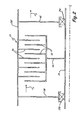
- FIG. 2 is a diagrammatic illustration of low pressure turbine 22 supported within engine 10 by the LPT bearing mounting system shown in FIG. 1 .
- LPT 22 is disposed between LPT case 23E and shaft 24, and comprises a plurality of blades 32 disposed between a plurality of vanes 34. Vanes 34 are suspended from LPT case 23 such that they remain stationary during operation of LPT 22. Blades 32 are connected to shaft 24 through support rotor 36 such that they rotate during operation of LPT 22.
- LPT case 23E is maintained concentrically disposed about shaft 24 by forward strut 38 and aft strut 40. Forward strut 38 and aft strut 40 maintain contact with and provide support to shaft 24 through bearing 25D and bearing 25C, respectively.
- support rotor 36 is straddled by a pair of bearings to facilitate controlled rotation of shaft 24 and to promote sealing at the unsupported ends of blades 32 and vanes 34.
- the forward and aft positions of bearings 25D and 25C provide improved rotor stability and enhanced tip clearance control for blades 32 by, among other things, reducing rotor tilt.
- the high rotational speed of shaft 24 results in rotational vibration and oscillation shaft 24.
- the vibration causes flexure of shaft 24, which causes arcuate tilting of support rotor 36 and LPT blades 32 with respect to engine centerline CL.
- the tilting of support rotor 36 results in radial displacement of support rotor 36, causing the distal tips of blades 32 to pull away from LPT case 23E, thus allowing primary air A P to escape without impinging upon blades 32.
- Rotor tilt and radial displacement of blades 32 is exacerbated by long lengths of unsupported shaft.
- the present invention helps to prevent tilt by providing increased support to low pressure shaft 24.
- bearing 25C and bearing 25D reduce the amount of unsupported shaft length of shaft 24 to reduce vibration of shaft 24.
- a resulting benefit to reducing unsupported length of shaft 24 by locating bearings 25C and 25D forward and aft of support rotor 36 is an increase in the critical speed of low pressure shaft 20.
- the critical speed of a shaft is qualified as the maximum safe speed at which the shaft will rotate under operating conditions.
- Factors that influence critical speed of a shaft include shaft diameter, unsupported shaft length, material properties and torque loading.
- Providing two bearings that directly support shaft 24 from LPT case 23E reduces the amount of unsupported shaft length and thus reduces the capacity of shaft 24 to vibrate or fluctuate. This permits the critical speed of shaft 24 to be increased. Conversely, this permits the diameter of shaft 24 to be reduced while maintaining the same critical speed.
- FIG. 3 is a schematic cross sectional view of an exemplary bearing mounting system for low pressure turbine 22 of gas turbine engine 10 of FIG. 1 .
- the bearing mounting system includes support rotor 36, forward strut 38 and aft strut 40, which illustrate the shaft-supporting and space-saving advantages of the present invention.
- LPT 22 including support rotor 36, forward strut 38 and aft strut 40, is not identically pictured in FIG. 3 as it is in FIG. 1 , it performs an equivalent function for the purposes of the invention and illustrates another embodiment of the bearing mounting system of the present invention.
- Low pressure turbine 22 also includes LPT case 23E, shaft 24, forward bearing 25D, aft bearing 25C, LPT blades 32 and LPT vanes 34.
- LPT 22 is disposed within engine 10 between exit guide vane 41 for HPT 20 of case 23D, and exit guide vane 42 for LPT 22 of case 23E.
- Exit guide vane 41 is disposed between the outer diameter surface of case 23D and forward strut 38.
- the outer diameter end of exit guide vane 42 is connected to the aft end of LPT case 23E, while the inner diameter end is supported by aft strut 40.
- Forward strut 38 and aft strut 40 are supported on shaft 24 by bearing 25D and bearing 25C, respectively.
- Bearing 25D and bearing 25C are positioned forward and aft of support rotor 36 to reduce the amount of unsupported shaft length of shaft 24.
- sealing elements of LPT blades 32 rotate between LPT vanes 34 with reduced separation from sealing elements on LPT case 23E, increasing the amount of primary air A P that impinges on LPT blades 32 and increasing the overall efficiency of engine 10.
- LPT vanes 34 are suspended from LPT case 23E, such as with hooked engagements 43.
- the inner diameter ends of LPT vanes 34 are provided with abradable seal members 44, which mate with knife edge seal elements of LPT blades 32.
- LPT blades 32 are connected at their inner diameter ends with a plurality of rotor disks 46A - 46F. In the embodiment shown, there are six rotors comprising six blade and vane stages, but in other low pressure turbine designs more or fewer stages are used.
- Each rotor disk 46 includes axial extending arms 48, through which threaded fasteners 50 are inserted to secure rotors 46 to each other.
- rotors 46 are maintained in an annular rotor stack that rotates as a unit about centerline CL. Between each adjoining arm 48 are positioned a plurality of knife edge seal elements 52 that abut with abradable seal members 44 of LPT vanes 34. The radially outer ends of LPT blades 32 are provided with knife edge seal members 54 that abut with abradable seal members 56 positioned on the inner surface of LPT case 23E. As such, the radial position of the stack of rotors 46A - 46F is critical to maintaining proper sealing between knife edge elements 52 and 54 and abradable elements 44 and 56, respectively, as shaft 24 rotates within LPT case 23E. Rotors 46A - 46F are supported inside LPT case 23E by support rotor 36, which extends to shaft 24.
- Support rotor 36 connects the stack of rotors 46A - 46F to shaft 24.
- a single conical support rotor 36 is used to support LPT 22. It is desirable to use a single support rotor to support LPT 22 to reduce the overall weight of engine 10 and to reduce the rotating mass of LPT 22.
- the exact position of support rotor 36 depends on the specific design parameters of LPT 22. For example, placement of support rotor 36 is selected to balance rotors 46A - 46C of LPT 22.
- support rotor 36 extends from the fourth stage rotor 46D, which is most close to the center of mass of LPT 22 since the fifth and sixth stage blades outweigh the first through third stage blades.
- LPT 22 is balanced upon support rotor 36 such that tendency of rotor 36 to tilt forward or backward is reduced.
- Support rotor 36 comprises a conical support that is integrally formed with fourth stage rotor 46D at its outer diameter end.
- the inner diameter end of support rotor 36 includes axial flange 58, which connects with shaft 24 through axial spline 60.
- Spline 60 prevents relative rotation between support 36 and shaft 24.
- Support rotor 36 maintains LPT blades 32 a fixed distance from shaft 24 and remains generally rigid as shaft 24 rotates during operation of engine 10.
- Shaft 24 is subjected to various dynamic forces that cause vibration in shaft 24, which affect the proper spacing of knife edge seal members 54 from abradable seal members 56.
- Shaft 24 is thus provided with forward strut 38 and aft strut 40 that assist in maintaining shaft 24 spaced a fixed distance from LPT case 23E.
- Struts 38 and 40 provide rigid spacers that directly connect shaft 24 with stationary elements within engine 10, such as case 23D, case 23E, vane 41 or vane 42.
- strut 38 and strut 40 comprise annular disk-like members that completely encircle shaft 24.
- strut 38 and strut 40 comprise intermittent shaft-like members that provide radial "wagon wheel” support to shaft 24.
- the outer end of aft strut 40 extends from the inner diameter end of exit guide vane 42, which is rigidly connected with static LPT case 23E.
- the inner end of aft strut 40 is joined with flange 62 of lubrication system 64.
- Bearing 25C is disposed between flange 62 and shaft 24.
- Lubrication system 64 comprises a dispensing system for providing lubricating oil to bearing 25C and includes a horizontally extending conduit member (not shown) that extends along centerline CL within shaft 24. Lubrication system 64 also includes sealing elements 66 that retain the lubricating oil within lubrication system 64 and shaft 24. Lubrication system 64 remains stationary during operation of engine 10 such that flange 62, strut 40 and exit guide vane 42 provide a rigid, direct link between bearing 25C and LPT case 23E. As such, the position of the aft end of shaft 24 located downstream of support rotor 36 is maintained a fixed distance from case 23E. Likewise, a middle segment of shaft 24 upstream of support rotor 36 is maintained a fixed distance from case 23E through a similar rigid support system.
- shaft 24 includes platform 68 upon which bearing 25D is positioned.
- Platform 68 includes radially extending portion 70, which provides radial clearance from shaft 24, and axially extending portion 72, which provides a base for mounting bearing 25D.
- Platform 68 thus provides a pocket in which other components or systems of engine 10 can be mounted.
- Platform 68 provides additional space within case 23E and case 23D without adding to the diameter or length of engine 10.
- the space inside platform 68 is used to store bearing support elements (not shown) for HPT 20 ( FIG. 1 ) in one embodiment of the invention.
- Bearing 25D is still directly and rigidly disposed between stationary support elements and rotating shaft 24.
- Axial flange 58 of support rotor 36 includes a radially extending element that joins with radial extending portion 70 of platform 68 at spline 74.
- platform 68 is rigidly connected with shaft 24 through axial flange 58 such that support rotor 36, platform 68 and shaft 24 rotate as a unit.
- Bearing 25D is positioned on axially extending portion 72 of platform 68.
- Bearing 25D is provided with a lubrication system (not shown) comparable to that of lubrication system 64. Sealing element 76 confines the lubricating oil within the lubricating system.
- Forward strut 38 extends from bearing 25D radially out to the inner diameter end of exit guide vane 41, which is bolted to LPT case 23E through mid-turbine frame of case 23D.
- the spacing between LPT case 23E from platform 68 of shaft 24 is maintained fixed through the rigid connection of case 23D, exit guide vane 41 and forward strut 38.
- the low pressure spool of engine 10 is provided with two structural systems that provide direct support to the portion of shaft 24 supporting LPT 22.
- the structural systems are provided with bearings that straddle rotor support 36 of LPT 22 to stabilize shaft 24 during rotation.
- Each structural system is connected with LPT case 23E by rigid, stationary members to prevent radial displacement of shaft 24 within LPT case 23E.
- the precise positioning of the structural systems forward and aft of rotor support 36 are determined to assist in controlling vibration of shaft 24 and tilt of support rotor 36.
Landscapes
- Engineering & Computer Science (AREA)
- Mechanical Engineering (AREA)
- General Engineering & Computer Science (AREA)
- Chemical & Material Sciences (AREA)
- Combustion & Propulsion (AREA)
- Turbine Rotor Nozzle Sealing (AREA)
- Structures Of Non-Positive Displacement Pumps (AREA)
Abstract
Description
- The present invention relates generally to gas turbine engines, and more particularly to a bearing mounting system for supporting a low pressure turbine in a gas turbine engine. A gas turbine engine typically includes a high pressure spool, a combustion system and a low pressure spool disposed within an engine case to form a generally axial, serial flow path about the engine centerline. The high pressure spool includes a high pressure turbine, a high pressure shaft extending axially forward from the high pressure turbine, and a high pressure compressor connected to a forward end of the high pressure shaft. The low pressure spool includes a low pressure turbine, which is disposed downstream of the high pressure turbine, a low pressure shaft, which typically extends coaxially through the high pressure shaft, and a low pressure compressor connected to a forward end of the low pressure shaft, forward of the high pressure compressor. The combustion system is disposed between the high pressure compressor and the high pressure turbine and receives compressed air from the compressors and fuel provided by a fuel injection system. A combustion process is carried out within the combustion system to produce high energy gases to produce thrust and turn the high and low pressure turbines, which drive the compressors to sustain the combustion process.
- Compressors and turbines are comprised of alternating stages of blades and vanes that are arranged radially around a center axis of the engine within the axial flow path of the engine case. For example, in the low pressure turbine, blades are connected to the low pressure shaft such that they rotate about the engine centerline, while vanes are supported by the engine case such that they remain stationary between the blades. Engine efficiency depends greatly on the ability of the engine to pass airflow through the blades and vanes within the axial flow path without leakage. To increase efficiency, the radially outer end of the blades are designed to come into close proximity with the stationary engine case as the high energy gases from the combustion process rotate the turbines. Typically, a sealing system is provided to reduce leakage from around the tips of the blades. For example, an abradable seal is positioned on the inner diameter surface of the engine case above the low pressure turbine, and a knife edge is positioned on the tip of each of the low pressure turbine blades to seal the air flow path. The ability of this sealing system to function depends on the consistency with which the low pressure shaft rotates about the engine centerline.
- In many conventional engines, the low pressure turbine is typically supported within the engine case by a support rotor connected near the aft end of the low pressure turbine. Typically, the aft end of the low pressure shaft is supported by a single bearing, often referred to as the number five bearing, positioned either forward or aft of the support rotor. The use of a single number five bearing, however, can result in rotor dynamics issues such as turbine instability and vibration. For example, a single bearing support can lead to forward or rearward tilting of the support rotor. Rotor tilt causes the turbine blades and the knife edge seals to pull away from the abradable material and the engine case, causing an air leak and decreasing engine efficiency. One factor contributing to rotor tilt is large amounts unsupported shaft length, which results from using a single bearing to support the low pressure turbine. Large unsupported shaft lengths not only increase shaft vibration, but also reduce the maximum rotational speed, or critical speed, of the shaft, thus limiting the operational speeds of the engine. Critical speed can be increased by increasing the diameter of the shaft, which unfavorably increases shaft weight and area.
- Previous attempts have been made to support low pressure turbines using more than one bearing, but have resulted in overly complex systems that do not address rotor dynamics issues for turbines having a single support rotor. For example,
U.S. Patent No. 5,074,109 to Mandet et al . discloses a low pressure turbine having a rotor drum supported by two transverse elements, and a shaft supported by two bearings. Also,U.S. Patent No. 5,813,214 to Moniz et al . discloses a low pressure turbine supported by a single rotor, an aft bearing supporting the low pressure shaft and a forward bearing supporting the high pressure shaft. There is, therefore, a need for a mounting system that improves rotor dynamics and engine efficiency in low pressure spool systems without increasing size, weight and complexity of the system. - The present invention in one aspect is directed to a bearing mounting system for use in a gas turbine engine having a low pressure turbine supported on a low pressure shaft through a support rotor. The bearing mounting system comprises a low pressure turbine case, a forward bearing and an aft bearing, and a forward support structure and an aft support structure. The low pressure turbine case surrounds the low pressure turbine. The forward bearing and the aft bearing are positioned on the low pressure shaft to straddle the support rotor. The forward support structure and the aft support structure connect the forward bearing and the aft bearing, respectively, to the low pressure turbine case. The low pressure shaft extends axially between the forward bearing and the aft bearing. In one embodiment, the turbine comprises a plurality of adjacent rotor disks, and the support rotor comprises a conical support connecting one of the rotor disks with the shaft.
- From another aspect, the invention provides a bearing mounting system for a low pressure turbine in a gas turbine engine, the bearing mounting system comprising:
- a low pressure shaft configured to rotate about an engine centerline;
- a single support rotor connecting the low pressure shaft with a plurality of low pressure turbine blades;
- a forward bearing support and an aft bearing support that straddle the support rotor;
- a forward bearing disposed between the forward bearing support and the low pressure shaft; and
- an aft bearing disposed between the aft bearing support and the low pressure shaft.
- a low pressure turbine case surrounding the low pressure turbine rotor stack;
- a forward bearing and an aft bearing positioned on the low pressure shaft and straddling the support rotor; and
- a forward support structure and an aft support structure connecting the forward bearing and the aft bearing, respectively, to the low pressure turbine case;
- In one embodiment, the forward bearing and the aft bearing are positioned to control tilting of the support rotor.
- In a further embodiment, the low pressure turbine shaft includes a radially extending platform upon which the forward bearing is mounted.
- In a further embodiment, the forward support structure and the aft support structure are connected to the low pressure turbine case through guide vanes.
- In a further embodiment, the support rotor comprises a single conical member positioned on portion of the low pressure turbine shaft disposed between the forward bearing and the aft bearing.
- From a further aspect, the invention provides a gas turbine engine comprising:
- an outer annular engine case;
- a high pressure spool disposed within the engine case and configured as a gas generator, the high pressure spool comprising:
- a high pressure compressor;
- a high pressure turbine; and
- a high pressure shaft connecting the high pressure compressor with the high pressure turbine; and
- a low pressure spool disposed within the engine case, the low pressure spool comprising:
- a low pressure compressor disposed forward of the high pressure compressor;
- a low pressure turbine disposed aft of the high pressure turbine, the low pressure turbine comprising:
- a plurality of rotor disks;
- a plurality of rotor blades extending from the rotor disks; and
- a plurality of knife edge seal elements disposed at distal tips of the rotor blades and configured to engage mating abradable seals on the engine case at a clearance gap;
- a low pressure conical support rotor connected to one of the rotor disks;
- a low pressure shaft connecting the conical support rotor with the low pressure compressor;
- a forward support bearing positioned on the low pressure shaft forward of the conical support rotor;
- a forward support structure connecting the forward support bearing with the engine case;
- an aft support bearing positioned on the low pressure shaft aft of the conical support rotor; and
- an aft support structure connecting the aft support bearing with the engine case;
-
-
FIG. 1 is a schematic cross sectional view of a gas turbine engine in which a bearing mounting system of the present invention is used to support a low pressure turbine. -
FIG. 2 is a diagrammatic illustration of the bearing mounting system ofFIG. 1 . -
FIG. 3 is a schematic cross sectional view of a low pressure turbine including one embodiment of the bearing mounting system ofFIG. 2 . -
FIG. 1 shows a cross section ofgas turbine engine 10 in which the bearing mounting system of the present invention is used. AlthoughFIG. 1 depicts a gas turbine engine typically used for aircraft propulsion, the invention is readily applicable to gas turbine generators and other similar systems incorporating rotor-supported, shaft-driven turbines.Gas turbine engine 10 comprises a dual-spool turbofan engine in which the advantages of the present invention are particularly well illustrated.Gas turbine engine 10, of which the operational principles are well known in the art, comprises fan 12, low pressure compressor (LPC) 14, high pressure compressor (HPC) 16,combustor section 18, high pressure turbine (HPT) 20 and low pressure turbine (LPT) 22, which are each concentrically disposed around longitudinal engine centerline CL. Fan 12 is enclosed at its outer diameter withinfan case 23A. Likewise, the other engine components are correspondingly enclosed at their outer diameters within various engine casings, includingLPC case 23B,HPC case 23C,HPT case 23D (including the mid-turbine frame) andLPT case 23E. Fan 12 andLPC 14 are connected toLPT 22 throughshaft 24, which is supported by ball bearing 25A androller bearing 25B toward its forward end, and ball bearing 25C and ball bearing 25D toward its aft end. Together, fan 12,LPC 14,LPT 22 andshaft 24 comprise the low pressure spool.HPC 16 is connected toHPT 20 throughshaft 26, which is supported withinengine 10 atball bearing 25E androller bearing 25F. Together,HPC 16,HPT 20 andshaft 26 comprise the high pressure spool. - Inlet air A enters
engine 10 whereby it is divided into streams of primary air AP and secondary air AS after passing through fan 12. Fan 12 is rotated bylow pressure turbine 22 throughshaft 24 to accelerate secondary air As (also known as bypass air) throughexit guide vanes 28, thereby producing a major portion of the thrust output ofengine 10. Primary air AP (also known as gas path air) is directed first intolow pressure compressor 14 and then intohigh pressure compressor 16.LPC 14 andHPC 16 work together to incrementally step up the pressure of primary air AP. HPC 16 is rotated byHPT 20 throughshaft 28 to provide compressed air tocombustor section 18. The compressed air is delivered tocombustor 18, along with fuel throughinjectors high pressure turbine 20 andlow pressure turbine 22, which is comprised ofblades 32 andvanes 34. Primary air AP continues throughgas turbine engine 10 whereby it is typically passed through an exhaust nozzle to further produce thrust. - As discussed above,
gas turbine engine 10 includes a plurality of bearings to support the low pressure spool and the high pressure spool withinfan case 23A,LPC case 23B,HPC case 23C,HPT case 23D andLPT case 23E. For the purposes of this application, bearing 25A is referred to as the No. 1 bearing, 25B as the No. 2 bearing, 25E as the No. 3 bearing, 25F as the No. 4 bearing, bearing 25D as the No. 5 bearing and bearing 25C as the No. 6 bearing. The selection of roller bearings, ball bearings or other bearing types depends on design needs, any of which can be used with the bearing mounting system of the present invention. The bearing mounting system of the present invention includessupport rotor 36, which supportsblades 32; forward strut 38, which supports the No. 5 bearing (bearing 25D); andaft strut 40, which supports the No. 6 bearing (25C). In one embodiment, bearing 25C and bearing25D straddle LPT 22 and connect withLPT case 23E to improve rotor dynamics ofLPT 22, which leads to improved efficiency ofengine 10. - After being compressed in
LPC 14 andHPC 16 and participating in a combustion process in combustor 18 (FIG. 1 ) to increase pressure and energy, primary air AP flows throughHPT 20 andLPT 22 such thatblades 32 extract energy from the flow of primary air AP. Primary air AP impinges onblades 32 to cause rotation ofsupport rotor 36 andshaft 24. In order to maintain the efficiency of the combustion process it is necessary to seal the path along which primary air AP flows. It is particularly advantageous to seal at the free ends ofvanes 34 andblades 32 as they extend fromLPT case 23E androtor 36, respectively. For example, in order to maintain the mechanical efficiency ofengine 10 it is necessary to ensure that the energy put into primary air AP translates into useful work of rotatingshaft 24. Any air allowed to escapeLPT 22 by passing through the gaps at the free ends ofblades 32 andvanes 34 reduces the efficiency ofengine 10. Thus, it is desirable to maintain the gap between, for example,blades 32 andLPT case 23E as small as possible. Various sealing configurations, such as labyrinth, knife edge and brush seals, are provided to seal or reduce air leakage at these gaps. In order to assist in maintaining the desired clearance height of these sealing systems during various operating modes ofengine 10, the LPT bearing mounting system of the present invention is used. Specifically, bearing 25D is positioned directly uponshaft 24 and is supported byforward strut 38 upstream ofrotor 36.Bearing 25C is positioned directly uponshaft 24 and is supported byaft strut 40 downstream ofrotor 36. The locations ofbearings support rotor 36, maximize support ofshaft 24 to reduce shaft vibration. -
FIG. 2 is a diagrammatic illustration oflow pressure turbine 22 supported withinengine 10 by the LPT bearing mounting system shown inFIG. 1 .LPT 22 is disposed betweenLPT case 23E andshaft 24, and comprises a plurality ofblades 32 disposed between a plurality ofvanes 34.Vanes 34 are suspended from LPT case 23 such that they remain stationary during operation ofLPT 22.Blades 32 are connected toshaft 24 throughsupport rotor 36 such that they rotate during operation ofLPT 22.LPT case 23E is maintained concentrically disposed aboutshaft 24 byforward strut 38 andaft strut 40.Forward strut 38 and aft strut 40 maintain contact with and provide support toshaft 24 through bearing 25D and bearing 25C, respectively. As such,support rotor 36 is straddled by a pair of bearings to facilitate controlled rotation ofshaft 24 and to promote sealing at the unsupported ends ofblades 32 andvanes 34. - The forward and aft positions of
bearings blades 32 by, among other things, reducing rotor tilt. The high rotational speed ofshaft 24 results in rotational vibration andoscillation shaft 24. The vibration causes flexure ofshaft 24, which causes arcuate tilting ofsupport rotor 36 andLPT blades 32 with respect to engine centerline CL. The tilting ofsupport rotor 36 results in radial displacement ofsupport rotor 36, causing the distal tips ofblades 32 to pull away fromLPT case 23E, thus allowing primary air AP to escape without impinging uponblades 32. Rotor tilt and radial displacement ofblades 32 is exacerbated by long lengths of unsupported shaft. The present invention helps to prevent tilt by providing increased support tolow pressure shaft 24. In particular, bearing 25C and bearing 25D reduce the amount of unsupported shaft length ofshaft 24 to reduce vibration ofshaft 24. - A resulting benefit to reducing unsupported length of
shaft 24 by locatingbearings support rotor 36 is an increase in the critical speed oflow pressure shaft 20. The critical speed of a shaft is qualified as the maximum safe speed at which the shaft will rotate under operating conditions. Factors that influence critical speed of a shaft include shaft diameter, unsupported shaft length, material properties and torque loading. Providing two bearings that directly supportshaft 24 fromLPT case 23E reduces the amount of unsupported shaft length and thus reduces the capacity ofshaft 24 to vibrate or fluctuate. This permits the critical speed ofshaft 24 to be increased. Conversely, this permits the diameter ofshaft 24 to be reduced while maintaining the same critical speed. As a result of the concentric arrangement betweenshaft 24 and shaft 26 (FIG. 1 ), this also allows the diameter ofhigh pressure shaft 26 to be decreased as well. Decreasing the diameters of the respective shafts provides additional space withinengine 10 to shift or accommodate other elements ofengine 10 or to reduce the overall diameter ofengine 10. The decrease in diameters also results in a net weight reduction forengine 10.. Thus, by providing radial support toshaft 24 at positions forward and aft ofsupport rotor 36, the efficiency ofengine 10 is increased while reducing size and weight. -
FIG. 3 is a schematic cross sectional view of an exemplary bearing mounting system forlow pressure turbine 22 ofgas turbine engine 10 ofFIG. 1 . The bearing mounting system includessupport rotor 36,forward strut 38 andaft strut 40, which illustrate the shaft-supporting and space-saving advantages of the present invention. AlthoughLPT 22, includingsupport rotor 36,forward strut 38 andaft strut 40, is not identically pictured inFIG. 3 as it is inFIG. 1 , it performs an equivalent function for the purposes of the invention and illustrates another embodiment of the bearing mounting system of the present invention.Low pressure turbine 22 also includesLPT case 23E,shaft 24, forward bearing 25D, aft bearing 25C,LPT blades 32 and LPT vanes 34.LPT 22 is disposed withinengine 10 betweenexit guide vane 41 forHPT 20 ofcase 23D, and exitguide vane 42 forLPT 22 ofcase 23E.Exit guide vane 41 is disposed between the outer diameter surface ofcase 23D andforward strut 38. The outer diameter end ofexit guide vane 42 is connected to the aft end ofLPT case 23E, while the inner diameter end is supported byaft strut 40.Forward strut 38 and aft strut 40 are supported onshaft 24 by bearing 25D and bearing 25C, respectively.Bearing 25D and bearing 25C are positioned forward and aft ofsupport rotor 36 to reduce the amount of unsupported shaft length ofshaft 24. As such, sealing elements ofLPT blades 32 rotate betweenLPT vanes 34 with reduced separation from sealing elements onLPT case 23E, increasing the amount of primary air AP that impinges onLPT blades 32 and increasing the overall efficiency ofengine 10. - The outer diameter ends of
LPT vanes 34 are suspended fromLPT case 23E, such as withhooked engagements 43. The inner diameter ends ofLPT vanes 34 are provided withabradable seal members 44, which mate with knife edge seal elements ofLPT blades 32.LPT blades 32 are connected at their inner diameter ends with a plurality ofrotor disks 46A - 46F. In the embodiment shown, there are six rotors comprising six blade and vane stages, but in other low pressure turbine designs more or fewer stages are used. Each rotor disk 46 includes axial extendingarms 48, through which threadedfasteners 50 are inserted to secure rotors 46 to each other. As such, rotors 46 are maintained in an annular rotor stack that rotates as a unit about centerline CL. Between eachadjoining arm 48 are positioned a plurality of knifeedge seal elements 52 that abut withabradable seal members 44 of LPT vanes 34. The radially outer ends ofLPT blades 32 are provided with knifeedge seal members 54 that abut withabradable seal members 56 positioned on the inner surface ofLPT case 23E. As such, the radial position of the stack ofrotors 46A - 46F is critical to maintaining proper sealing betweenknife edge elements abradable elements shaft 24 rotates withinLPT case 23E.Rotors 46A - 46F are supported insideLPT case 23E bysupport rotor 36, which extends toshaft 24. -
Support rotor 36 connects the stack ofrotors 46A - 46F toshaft 24. In the embodiment shown, a singleconical support rotor 36 is used to supportLPT 22. It is desirable to use a single support rotor to supportLPT 22 to reduce the overall weight ofengine 10 and to reduce the rotating mass ofLPT 22. The exact position ofsupport rotor 36 depends on the specific design parameters ofLPT 22. For example, placement ofsupport rotor 36 is selected to balancerotors 46A - 46C ofLPT 22. In the embodiment shown,support rotor 36 extends from thefourth stage rotor 46D, which is most close to the center of mass ofLPT 22 since the fifth and sixth stage blades outweigh the first through third stage blades. Thus,LPT 22 is balanced uponsupport rotor 36 such that tendency ofrotor 36 to tilt forward or backward is reduced. -
Support rotor 36 comprises a conical support that is integrally formed withfourth stage rotor 46D at its outer diameter end. The inner diameter end ofsupport rotor 36 includesaxial flange 58, which connects withshaft 24 throughaxial spline 60.Spline 60 prevents relative rotation betweensupport 36 andshaft 24.Support rotor 36 maintains LPT blades 32 a fixed distance fromshaft 24 and remains generally rigid asshaft 24 rotates during operation ofengine 10.Shaft 24, however, is subjected to various dynamic forces that cause vibration inshaft 24, which affect the proper spacing of knifeedge seal members 54 fromabradable seal members 56.Shaft 24 is thus provided withforward strut 38 and aft strut 40 that assist in maintainingshaft 24 spaced a fixed distance fromLPT case 23E. -
Struts shaft 24 with stationary elements withinengine 10, such ascase 23D,case 23E,vane 41 orvane 42. In one embodiment, strut 38 and strut 40 comprise annular disk-like members that completely encircleshaft 24. In other embodiments, strut 38 and strut 40 comprise intermittent shaft-like members that provide radial "wagon wheel" support toshaft 24. In the embodiment shown, the outer end ofaft strut 40 extends from the inner diameter end ofexit guide vane 42, which is rigidly connected withstatic LPT case 23E. The inner end ofaft strut 40 is joined withflange 62 oflubrication system 64.Bearing 25C is disposed betweenflange 62 andshaft 24.Lubrication system 64 comprises a dispensing system for providing lubricating oil to bearing 25C and includes a horizontally extending conduit member (not shown) that extends along centerline CL withinshaft 24.Lubrication system 64 also includes sealingelements 66 that retain the lubricating oil withinlubrication system 64 andshaft 24.Lubrication system 64 remains stationary during operation ofengine 10 such thatflange 62,strut 40 andexit guide vane 42 provide a rigid, direct link between bearing 25C andLPT case 23E. As such, the position of the aft end ofshaft 24 located downstream ofsupport rotor 36 is maintained a fixed distance fromcase 23E. Likewise, a middle segment ofshaft 24 upstream ofsupport rotor 36 is maintained a fixed distance fromcase 23E through a similar rigid support system. - In the embodiment of
FIG. 3 ,shaft 24 includesplatform 68 upon which bearing 25D is positioned.Platform 68 includes radially extendingportion 70, which provides radial clearance fromshaft 24, and axially extendingportion 72, which provides a base for mountingbearing 25D.Platform 68 thus provides a pocket in which other components or systems ofengine 10 can be mounted.Platform 68 provides additional space withincase 23E andcase 23D without adding to the diameter or length ofengine 10. For example, the space insideplatform 68 is used to store bearing support elements (not shown) for HPT 20 (FIG. 1 ) in one embodiment of the invention.Bearing 25D is still directly and rigidly disposed between stationary support elements androtating shaft 24.Axial flange 58 ofsupport rotor 36 includes a radially extending element that joins withradial extending portion 70 ofplatform 68 at spline 74. Thus,platform 68 is rigidly connected withshaft 24 throughaxial flange 58 such thatsupport rotor 36,platform 68 andshaft 24 rotate as a unit.Bearing 25D is positioned on axially extendingportion 72 ofplatform 68.Bearing 25D is provided with a lubrication system (not shown) comparable to that oflubrication system 64. Sealingelement 76 confines the lubricating oil within the lubricating system.Forward strut 38 extends from bearing 25D radially out to the inner diameter end ofexit guide vane 41, which is bolted toLPT case 23E through mid-turbine frame ofcase 23D. Thus, the spacing betweenLPT case 23E fromplatform 68 ofshaft 24 is maintained fixed through the rigid connection ofcase 23D,exit guide vane 41 andforward strut 38. - The low pressure spool of
engine 10 is provided with two structural systems that provide direct support to the portion ofshaft 24 supportingLPT 22. The structural systems are provided with bearings that straddlerotor support 36 ofLPT 22 to stabilizeshaft 24 during rotation. Each structural system is connected withLPT case 23E by rigid, stationary members to prevent radial displacement ofshaft 24 withinLPT case 23E. The precise positioning of the structural systems forward and aft ofrotor support 36 are determined to assist in controlling vibration ofshaft 24 and tilt ofsupport rotor 36. As such, clearances ofLPT blades 32 withLPT case 23E are maintained within a smaller tolerance band such that leakage of primary air AP around the tips ofblades 32 is reduced and the efficiency ofengine 10 increases, as compared to engines not employing the bearing support system of the present invention. Furthermore, the structural systems permit smaller sizing ofshaft 24, which permits size reduction ofengine 10 or clears space withinengine 10. - Although the present invention has been described with reference to preferred embodiments, workers skilled in the art will recognize that changes may be made in form and detail without departing from the scope of the invention.
Claims (15)
- A bearing mounting system for supporting a low pressure turbine (22) in a gas turbine engine (10), the bearing mounting system comprising:a low pressure shaft (24) configured to rotate about an engine centerline (CL);a single support rotor (36) connecting the low pressure shaft (24) with a plurality of low pressure turbine blades (32);a forward bearing support (38) and an aft bearing support (40) that straddle the support rotor (36);a forward bearing (25D) disposed between the forward bearing support (38) and the low pressure shaft (24); andan aft bearing (25C) disposed between the aft bearing support (40) and the low pressure shaft (24).
- The bearing mounting system of claim 1 wherein the forward bearing support (38) and the aft bearing support (40) provide direct rigid connections to a low pressure turbine case (23E) surrounding the low pressure turbine blades (32).
- The bearing mounting system of claim 2 wherein the forward bearing support (38) and the aft bearing support (40) are directly connected to the low pressure shaft (36) through the forward bearing (25D) and aft bearing (25C), respectively.
- The bearing mounting system of claim 2 or 3 wherein the forward bearing support (38) includes a radially extending strut that connects to the low pressure turbine case (23E) through a mid-turbine frame (23D) and an exit guide vane (41).
- The bearing mounting system of claims 2 to 4 claim wherein the aft bearing support (40) includes a radially extending strut that connects to the low pressure turbine case (23E) through a guide vane (42).
- The bearing mounting system of of claims 2 to 5 wherein the forward bearing support (38) and the aft bearing support (40) maintain the low pressure turbine shaft (24) at a fixed distance from the low pressure turbine case (23E).
- The bearing mounting system of any preceding claim wherein the low pressure turbine shaft (24) includes a platform (68) for radially displacing the forward bearing (25D) from the engine centerline (CL).
- The bearing mounting system of any preceding claim wherein the support rotor (36) is disposed near a center of mass of the low pressure turbine (22).
- The bearing mounting system of any preceding claim wherein:the low pressure turbine (22) comprises a plurality of rotor disks (46A-46F) jointed to form a rotor stack; andthe support rotor (36) comprises a conical, annular body that is integrally connected with one of the rotor disks (46A-46F) at an outer diameter end, and connected at an inner diameter end to the low pressure turbine shaft (24) through a spline (60).
- The bearing mounting system of any preceding claim wherein the low pressure turbine shaft (24) extends axially within the forward (25D) and aft bearings (25C).
- A bearing mounting system for a gas turbine engine (10) having a low pressure turbine rotor stack supported on a low pressure shaft (24) through a support rotor (36), the bearing mounting system comprising:a low pressure turbine case (23E) surrounding the low pressure turbine rotor stack;a forward bearing (25D) and an aft bearing (25C) positioned on the low pressure shaft (24) and straddling the support rotor (36); anda forward support structure (38) and an aft support structure (40) connecting the forward bearing (25D) and the aft bearing (25C), respectively, to the low pressure turbine case (23E);wherein the low pressure shaft extends axially between the forward bearing (25D) and the aft bearing (25C).
- The bearing mounting system of claim 11 wherein the forward bearing (25D) and the aft bearing (25C) are positioned to control vibration of the low pressure turbine shaft (24).
- The bearing mounting system of claim 11 or 12 wherein the low pressure turbine rotor stack comprises a plurality of rotor disks (46A-46F) each having a plurality of radially extending turbine blades (32).
- The bearing mounting system of any of claim 13, further comprising:a plurality of knife edge seal elements (54) disposed at radial tips of the turbine blades (32); anda plurality of abradable seal elements (56) lining an interior surface of the low pressure turbine case (23E) to mate with the plurality of knife edge seal elements (54).
- The bearing mounting system of any of claims 11 to 14, where the forward bearing (25D) and the aft bearing (25C) are positioned to control blade tip leakage.
Applications Claiming Priority (1)
| Application Number | Priority Date | Filing Date | Title |
|---|---|---|---|
| US12/001,130 US8511986B2 (en) | 2007-12-10 | 2007-12-10 | Bearing mounting system in a low pressure turbine |
Publications (3)
| Publication Number | Publication Date |
|---|---|
| EP2071139A2 true EP2071139A2 (en) | 2009-06-17 |
| EP2071139A3 EP2071139A3 (en) | 2012-11-28 |
| EP2071139B1 EP2071139B1 (en) | 2014-09-10 |
Family
ID=40413915
Family Applications (1)
| Application Number | Title | Priority Date | Filing Date |
|---|---|---|---|
| EP08253959.4A Active EP2071139B1 (en) | 2007-12-10 | 2008-12-10 | Bearing mounting system in a low pressure turbine |
Country Status (2)
| Country | Link |
|---|---|
| US (1) | US8511986B2 (en) |
| EP (1) | EP2071139B1 (en) |
Cited By (18)
| Publication number | Priority date | Publication date | Assignee | Title |
|---|---|---|---|---|
| EP2700798A1 (en) * | 2012-08-21 | 2014-02-26 | Siemens Aktiengesellschaft | Turbomachine comprising a rotor and a casing |
| WO2014078157A1 (en) | 2012-11-14 | 2014-05-22 | United Technologies Corporation | Gas turbine engine with mount for low pressure turbine section |
| EP2809953A1 (en) | 2012-01-31 | 2014-12-10 | United Technologies Corporation | Gas turbine engine with high speed low pressure turbine section and bearing support features |
| RU2550212C2 (en) * | 2013-05-07 | 2015-05-10 | Закрытое акционерное общество "Уральский турбинный завод" | Support of fast-rotating rotor |
| RU2560655C1 (en) * | 2014-06-02 | 2015-08-20 | Российская Федерация, от имени которой выступает Министерство промышленности и торговли Российской Федерации (Минпромторг России) | Gas turbine engine support |
| US9951688B2 (en) | 2014-08-29 | 2018-04-24 | Rolls-Royce Plc | Low pressure shaft |
| EP3379055A1 (en) * | 2017-03-22 | 2018-09-26 | Rolls-Royce plc | Gas turbine engine |
| US10240526B2 (en) | 2012-01-31 | 2019-03-26 | United Technologies Corporation | Gas turbine engine with high speed low pressure turbine section |
| US10288011B2 (en) | 2012-01-31 | 2019-05-14 | United Technologies Corporation | Geared turbofan gas turbine engine architecture |
| EP3557074A1 (en) * | 2012-01-31 | 2019-10-23 | United Technologies Corporation | Gas turbine engine with high speed low pressure turbine section |
| US10794292B2 (en) | 2012-01-31 | 2020-10-06 | United Technologies Corporation | Geared turbofan gas turbine engine architecture |
| US10830130B2 (en) | 2012-04-25 | 2020-11-10 | Raytheon Technologies Corporation | Geared turbofan with three turbines all counter-rotating |
| US11021997B2 (en) | 2011-06-08 | 2021-06-01 | Raytheon Technologies Corporation | Flexible support structure for a geared architecture gas turbine engine |
| US11047337B2 (en) | 2011-06-08 | 2021-06-29 | Raytheon Technologies Corporation | Geared architecture for high speed and small volume fan drive turbine |
| US11053843B2 (en) | 2012-04-02 | 2021-07-06 | Raytheon Technologies Corporation | Geared turbofan engine with a high ratio of thrust to turbine volume |
| US11585276B2 (en) | 2012-01-31 | 2023-02-21 | Raytheon Technologies Corporation | Gas turbine engine with high speed low pressure turbine section and bearing support features |
| US11598223B2 (en) | 2012-01-31 | 2023-03-07 | Raytheon Technologies Corporation | Gas turbine engine with high speed low pressure turbine section and bearing support features |
| US11608786B2 (en) | 2012-04-02 | 2023-03-21 | Raytheon Technologies Corporation | Gas turbine engine with power density range |
Families Citing this family (31)
| Publication number | Priority date | Publication date | Assignee | Title |
|---|---|---|---|---|
| US8834095B2 (en) * | 2011-06-24 | 2014-09-16 | United Technologies Corporation | Integral bearing support and centering spring assembly for a gas turbine engine |
| US8992161B2 (en) | 2011-08-26 | 2015-03-31 | Honeywell International Inc. | Gas turbine engines including broadband damping systems and methods for producing the same |
| US9046001B2 (en) | 2011-08-29 | 2015-06-02 | Honeywell International Inc. | Annular bearing support dampers, gas turbine engines including the same, and methods for the manufacture thereof |
| US9297438B2 (en) | 2012-01-25 | 2016-03-29 | Honeywell International Inc. | Three parameter damper anisotropic vibration isolation mounting assembly |
| US10145266B2 (en) * | 2012-01-31 | 2018-12-04 | United Technologies Corporation | Gas turbine engine shaft bearing arrangement |
| US20130195647A1 (en) * | 2012-01-31 | 2013-08-01 | Marc J. Muldoon | Gas turbine engine bearing arrangement including aft bearing hub geometry |
| US9347374B2 (en) * | 2012-02-27 | 2016-05-24 | United Technologies Corporation | Gas turbine engine buffer cooling system |
| WO2014055102A1 (en) * | 2012-10-01 | 2014-04-10 | United Technologies Corporation | Low weight large fan gas turbine engine |
| US20150013301A1 (en) * | 2013-03-13 | 2015-01-15 | United Technologies Corporation | Turbine engine including balanced low pressure stage count |
| US20150267610A1 (en) * | 2013-03-13 | 2015-09-24 | United Technologies Corporation | Turbine enigne including balanced low pressure stage count |
| DE102013213517A1 (en) * | 2013-07-10 | 2015-01-15 | Rolls-Royce Deutschland Ltd & Co Kg | Aircraft engine |
| US9790857B2 (en) * | 2014-04-17 | 2017-10-17 | United Technologies Corporation | Multiple bearing stack retention |
| US20160047307A1 (en) * | 2014-08-15 | 2016-02-18 | General Electric Company | Power train architectures with low-loss lubricant bearings and low-density materials |
| US9995314B2 (en) | 2015-07-20 | 2018-06-12 | General Electric Company | Cooling system for a turbine engine |
| US10487739B2 (en) | 2015-07-20 | 2019-11-26 | General Electric Company | Cooling system for a turbine engine |
| US9932858B2 (en) | 2015-07-27 | 2018-04-03 | General Electric Company | Gas turbine engine frame assembly |
| US9702404B2 (en) | 2015-10-28 | 2017-07-11 | United Technologies Corporation | Integral centering spring and bearing support and method of supporting multiple damped bearings |
| US10094283B2 (en) | 2015-10-28 | 2018-10-09 | General Electric Company | Differential gas bearing for aircraft engines |
| US10654577B2 (en) * | 2017-02-22 | 2020-05-19 | General Electric Company | Rainbow flowpath low pressure turbine rotor assembly |
| US10294821B2 (en) | 2017-04-12 | 2019-05-21 | General Electric Company | Interturbine frame for gas turbine engine |
| US10539053B2 (en) | 2017-07-06 | 2020-01-21 | General Electric Company | Engine transportation apparatus |
| GB201918783D0 (en) | 2019-12-19 | 2020-02-05 | Rolls Royce Plc | Shaft with three bearings |
| GB201918781D0 (en) | 2019-12-19 | 2020-02-05 | Rolls Royce Plc | Improved shaft bearing positioning in a gas turbine engine |
| GB201918780D0 (en) | 2019-12-19 | 2020-02-05 | Rolls Royce Plc | Shaft bearings for gas turbine engine |
| GB201918779D0 (en) | 2019-12-19 | 2020-02-05 | Rolls Royce Plc | Shaft bearings |
| GB201918782D0 (en) | 2019-12-19 | 2020-02-05 | Rolls Royce Plc | Shaft bearing arrangement |
| GB201918777D0 (en) * | 2019-12-19 | 2020-02-05 | Rolls Royce Plc | Shaft bearing arrangement |
| CN113565587B (en) * | 2020-04-29 | 2023-06-06 | 中国航发商用航空发动机有限责任公司 | Dynamic balance tool, assembly and method for low-pressure turbine rotor |
| US11428160B2 (en) | 2020-12-31 | 2022-08-30 | General Electric Company | Gas turbine engine with interdigitated turbine and gear assembly |
| US11788470B2 (en) | 2021-03-01 | 2023-10-17 | General Electric Company | Gas turbine engine thermal management |
| US11702958B2 (en) | 2021-09-23 | 2023-07-18 | General Electric Company | System and method of regulating thermal transport bus pressure |
Citations (3)
| Publication number | Priority date | Publication date | Assignee | Title |
|---|---|---|---|---|
| US5074109A (en) | 1989-03-22 | 1991-12-24 | Societe Nationale D'etude Et De Construction De Moteurs D'aviation "S.N.E.C.M.A." | Low pressure turbine rotor suspension in a twin hub turbo-engine |
| US5361580A (en) | 1993-06-18 | 1994-11-08 | General Electric Company | Gas turbine engine rotor support system |
| US5813214A (en) | 1997-01-03 | 1998-09-29 | General Electric Company | Bearing lubrication configuration in a turbine engine |
Family Cites Families (19)
| Publication number | Priority date | Publication date | Assignee | Title |
|---|---|---|---|---|
| US3673802A (en) * | 1970-06-18 | 1972-07-04 | Gen Electric | Fan engine with counter rotating geared core booster |
| US3703081A (en) | 1970-11-20 | 1972-11-21 | Gen Electric | Gas turbine engine |
| US4251987A (en) * | 1979-08-22 | 1981-02-24 | General Electric Company | Differential geared engine |
| US4433955A (en) * | 1981-03-26 | 1984-02-28 | General Electric Company | Turbine arrangement |
| FR2515734A1 (en) * | 1981-11-05 | 1983-05-06 | Snecma | SYSTEM FOR ADJUSTING THE CENTERING OF A TURBOMACHINE WHEEL AND TURBOMACHINE PROVIDED WITH MEANS FOR APPLYING SAID SYSTEM |
| US4611464A (en) | 1984-05-02 | 1986-09-16 | United Technologies Corporation | Rotor assembly for a gas turbine engine and method of disassembly |
| US4659289A (en) * | 1984-07-23 | 1987-04-21 | United Technologies Corporation | Turbine side plate assembly |
| US4979872A (en) | 1989-06-22 | 1990-12-25 | United Technologies Corporation | Bearing compartment support |
| JP2630701B2 (en) * | 1991-10-21 | 1997-07-16 | 陸郎 野津 | Turbine rotor blades for symmetric blade turbines |
| US5211541A (en) * | 1991-12-23 | 1993-05-18 | General Electric Company | Turbine support assembly including turbine heat shield and bolt retainer assembly |
| US5971710A (en) * | 1997-10-17 | 1999-10-26 | United Technologies Corporation | Turbomachinery blade or vane with a permanent machining datum |
| US6708482B2 (en) * | 2001-11-29 | 2004-03-23 | General Electric Company | Aircraft engine with inter-turbine engine frame |
| US6732502B2 (en) * | 2002-03-01 | 2004-05-11 | General Electric Company | Counter rotating aircraft gas turbine engine with high overall pressure ratio compressor |
| US6846158B2 (en) * | 2002-09-06 | 2005-01-25 | General Electric Company | Method and apparatus for varying the critical speed of a shaft |
| FR2858649B1 (en) | 2003-08-05 | 2005-09-23 | Snecma Moteurs | TURBOMACHINE LOW PRESSURE TURBINE |
| US7097413B2 (en) | 2004-05-12 | 2006-08-29 | United Technologies Corporation | Bearing support |
| US7182519B2 (en) | 2004-06-24 | 2007-02-27 | General Electric Company | Methods and apparatus for assembling a bearing assembly |
| US7409819B2 (en) | 2004-10-29 | 2008-08-12 | General Electric Company | Gas turbine engine and method of assembling same |
| US7882693B2 (en) * | 2006-11-29 | 2011-02-08 | General Electric Company | Turbofan engine assembly and method of assembling same |
-
2007
- 2007-12-10 US US12/001,130 patent/US8511986B2/en active Active
-
2008
- 2008-12-10 EP EP08253959.4A patent/EP2071139B1/en active Active
Patent Citations (3)
| Publication number | Priority date | Publication date | Assignee | Title |
|---|---|---|---|---|
| US5074109A (en) | 1989-03-22 | 1991-12-24 | Societe Nationale D'etude Et De Construction De Moteurs D'aviation "S.N.E.C.M.A." | Low pressure turbine rotor suspension in a twin hub turbo-engine |
| US5361580A (en) | 1993-06-18 | 1994-11-08 | General Electric Company | Gas turbine engine rotor support system |
| US5813214A (en) | 1997-01-03 | 1998-09-29 | General Electric Company | Bearing lubrication configuration in a turbine engine |
Cited By (37)
| Publication number | Priority date | Publication date | Assignee | Title |
|---|---|---|---|---|
| US11021997B2 (en) | 2011-06-08 | 2021-06-01 | Raytheon Technologies Corporation | Flexible support structure for a geared architecture gas turbine engine |
| US11698007B2 (en) | 2011-06-08 | 2023-07-11 | Raytheon Technologies Corporation | Flexible support structure for a geared architecture gas turbine engine |
| US11635043B2 (en) | 2011-06-08 | 2023-04-25 | Raytheon Technologies Corporation | Geared architecture for high speed and small volume fan drive turbine |
| US11073106B2 (en) | 2011-06-08 | 2021-07-27 | Raytheon Technologies Corporation | Geared architecture for high speed and small volume fan drive turbine |
| US11047337B2 (en) | 2011-06-08 | 2021-06-29 | Raytheon Technologies Corporation | Geared architecture for high speed and small volume fan drive turbine |
| US11021996B2 (en) | 2011-06-08 | 2021-06-01 | Raytheon Technologies Corporation | Flexible support structure for a geared architecture gas turbine engine |
| EP3557074A1 (en) * | 2012-01-31 | 2019-10-23 | United Technologies Corporation | Gas turbine engine with high speed low pressure turbine section |
| US11585276B2 (en) | 2012-01-31 | 2023-02-21 | Raytheon Technologies Corporation | Gas turbine engine with high speed low pressure turbine section and bearing support features |
| EP2809953A1 (en) | 2012-01-31 | 2014-12-10 | United Technologies Corporation | Gas turbine engine with high speed low pressure turbine section and bearing support features |
| US10288010B2 (en) | 2012-01-31 | 2019-05-14 | United Technologies Corporation | Geared turbofan gas turbine engine architecture |
| US11913349B2 (en) | 2012-01-31 | 2024-02-27 | Rtx Corporation | Gas turbine engine with high speed low pressure turbine section and bearing support features |
| US10288011B2 (en) | 2012-01-31 | 2019-05-14 | United Technologies Corporation | Geared turbofan gas turbine engine architecture |
| US11598223B2 (en) | 2012-01-31 | 2023-03-07 | Raytheon Technologies Corporation | Gas turbine engine with high speed low pressure turbine section and bearing support features |
| US10794292B2 (en) | 2012-01-31 | 2020-10-06 | United Technologies Corporation | Geared turbofan gas turbine engine architecture |
| US10240526B2 (en) | 2012-01-31 | 2019-03-26 | United Technologies Corporation | Gas turbine engine with high speed low pressure turbine section |
| US11448124B2 (en) | 2012-04-02 | 2022-09-20 | Raytheon Technologies Corporation | Geared turbofan engine with a high ratio of thrust to turbine volume |
| US11608786B2 (en) | 2012-04-02 | 2023-03-21 | Raytheon Technologies Corporation | Gas turbine engine with power density range |
| US11970984B2 (en) | 2012-04-02 | 2024-04-30 | Rtx Corporation | Gas turbine engine with power density range |
| US12055093B2 (en) | 2012-04-02 | 2024-08-06 | Rtx Corporation | Geared turbofan engine with a high ratio of thrust to turbine volume |
| US11053843B2 (en) | 2012-04-02 | 2021-07-06 | Raytheon Technologies Corporation | Geared turbofan engine with a high ratio of thrust to turbine volume |
| US10830130B2 (en) | 2012-04-25 | 2020-11-10 | Raytheon Technologies Corporation | Geared turbofan with three turbines all counter-rotating |
| WO2014029580A1 (en) * | 2012-08-21 | 2014-02-27 | Siemens Aktiengesellschaft | Fluid dynamics machine comprising a rotor and a housing |
| EP2700798A1 (en) * | 2012-08-21 | 2014-02-26 | Siemens Aktiengesellschaft | Turbomachine comprising a rotor and a casing |
| CN104583563B (en) * | 2012-08-21 | 2016-09-28 | 西门子公司 | Including rotor and the fluid machinery of housing |
| CN104583563A (en) * | 2012-08-21 | 2015-04-29 | 西门子公司 | Fluid dynamics machine comprising a rotor and a housing |
| JP2018135889A (en) * | 2012-11-14 | 2018-08-30 | ユナイテッド テクノロジーズ コーポレイションUnited Technologies Corporation | Gas turbine engine |
| EP3594483A1 (en) * | 2012-11-14 | 2020-01-15 | United Technologies Corporation | Gas turbine engine with mount for low pressure turbine section |
| JP2017160911A (en) * | 2012-11-14 | 2017-09-14 | ユナイテッド テクノロジーズ コーポレイションUnited Technologies Corporation | Gas turbine engine |
| WO2014078157A1 (en) | 2012-11-14 | 2014-05-22 | United Technologies Corporation | Gas turbine engine with mount for low pressure turbine section |
| EP2920445A1 (en) | 2012-11-14 | 2015-09-23 | United Technologies Corporation | Gas turbine engine with mount for low pressure turbine section |
| JP2015536409A (en) * | 2012-11-14 | 2015-12-21 | ユナイテッド テクノロジーズ コーポレイションUnited Technologies Corporation | Gas turbine engine with attachment for low pressure turbine section |
| EP2920445A4 (en) * | 2012-11-14 | 2015-12-16 | United Technologies Corp | Gas turbine engine with mount for low pressure turbine section |
| RU2550212C2 (en) * | 2013-05-07 | 2015-05-10 | Закрытое акционерное общество "Уральский турбинный завод" | Support of fast-rotating rotor |
| RU2560655C1 (en) * | 2014-06-02 | 2015-08-20 | Российская Федерация, от имени которой выступает Министерство промышленности и торговли Российской Федерации (Минпромторг России) | Gas turbine engine support |
| EP2990596B1 (en) * | 2014-08-29 | 2021-04-21 | Rolls-Royce plc | Low pressure shaft |
| US9951688B2 (en) | 2014-08-29 | 2018-04-24 | Rolls-Royce Plc | Low pressure shaft |
| EP3379055A1 (en) * | 2017-03-22 | 2018-09-26 | Rolls-Royce plc | Gas turbine engine |
Also Published As
| Publication number | Publication date |
|---|---|
| US8511986B2 (en) | 2013-08-20 |
| EP2071139B1 (en) | 2014-09-10 |
| EP2071139A3 (en) | 2012-11-28 |
| US20090148271A1 (en) | 2009-06-11 |
Similar Documents
| Publication | Publication Date | Title |
|---|---|---|
| EP2071139B1 (en) | Bearing mounting system in a low pressure turbine | |
| US10352195B2 (en) | Non-contacting seals for geared gas turbine engine bearing compartments | |
| US10539020B2 (en) | Two spool gas turbine engine with interdigitated turbine section | |
| EP2615289B1 (en) | Turbofan with gear-driven compressor and fan-driven core | |
| US10036279B2 (en) | Thrust bearing | |
| US10774668B2 (en) | Intersage seal assembly for counter rotating turbine | |
| CN108005786B (en) | Rotor shaft structure for gas turbine engine and method of assembling the same | |
| US10975713B2 (en) | Hydrostatic seal with aft tooth | |
| US11225975B2 (en) | Gas turbine engine fan | |
| EP3222811A1 (en) | Damping vibrations in a gas turbine | |
| US11230939B2 (en) | Vane seal system and seal therefor | |
| US10294821B2 (en) | Interturbine frame for gas turbine engine | |
| US20200191017A1 (en) | Bearing assembly including active vibration control | |
| US20160003163A1 (en) | Gas turbine engine with short transition duct | |
| US10443443B2 (en) | Non-contacting seals for geared gas turbine engine bearing compartments | |
| US11795839B2 (en) | Structural assembly for a gas turbine engine | |
| EP3722562A1 (en) | Non-contacting seals for geared gas turbine engine bearing compartments | |
| US11215061B2 (en) | Blade with wearable tip-rub-portions above squealer pocket | |
| US11852026B1 (en) | Exo-bearing for a turbomachine | |
| US20240141795A1 (en) | Flow splitter | |
| EP4365407A1 (en) | Fan blade for a gas turbine engine |
Legal Events
| Date | Code | Title | Description |
|---|---|---|---|
| PUAI | Public reference made under article 153(3) epc to a published international application that has entered the european phase |
Free format text: ORIGINAL CODE: 0009012 |
|
| AK | Designated contracting states |
Kind code of ref document: A2 Designated state(s): AT BE BG CH CY CZ DE DK EE ES FI FR GB GR HR HU IE IS IT LI LT LU LV MC MT NL NO PL PT RO SE SI SK TR |
|
| AX | Request for extension of the european patent |
Extension state: AL BA MK RS |
|
| PUAL | Search report despatched |
Free format text: ORIGINAL CODE: 0009013 |
|
| AK | Designated contracting states |
Kind code of ref document: A3 Designated state(s): AT BE BG CH CY CZ DE DK EE ES FI FR GB GR HR HU IE IS IT LI LT LU LV MC MT NL NO PL PT RO SE SI SK TR |
|
| AX | Request for extension of the european patent |
Extension state: AL BA MK RS |
|
| RIC1 | Information provided on ipc code assigned before grant |
Ipc: F02C 7/06 20060101ALI20121025BHEP Ipc: F01D 25/16 20060101AFI20121025BHEP |
|
| 17P | Request for examination filed |
Effective date: 20130524 |
|
| RBV | Designated contracting states (corrected) |
Designated state(s): AT BE BG CH CY CZ DE DK EE ES FI FR GB GR HR HU IE IS IT LI LT LU LV MC MT NL NO PL PT RO SE SI SK TR |
|
| AKX | Designation fees paid |
Designated state(s): DE GB |
|
| GRAP | Despatch of communication of intention to grant a patent |
Free format text: ORIGINAL CODE: EPIDOSNIGR1 |
|
| INTG | Intention to grant announced |
Effective date: 20140103 |
|
| GRAP | Despatch of communication of intention to grant a patent |
Free format text: ORIGINAL CODE: EPIDOSNIGR1 |
|
| INTG | Intention to grant announced |
Effective date: 20140509 |
|
| GRAS | Grant fee paid |
Free format text: ORIGINAL CODE: EPIDOSNIGR3 |
|
| GRAA | (expected) grant |
Free format text: ORIGINAL CODE: 0009210 |
|
| AK | Designated contracting states |
Kind code of ref document: B1 Designated state(s): DE GB |
|
| REG | Reference to a national code |
Ref country code: GB Ref legal event code: FG4D |
|
| REG | Reference to a national code |
Ref country code: DE Ref legal event code: R096 Ref document number: 602008034313 Country of ref document: DE Effective date: 20141023 |
|
| REG | Reference to a national code |
Ref country code: DE Ref legal event code: R097 Ref document number: 602008034313 Country of ref document: DE |
|
| PLBE | No opposition filed within time limit |
Free format text: ORIGINAL CODE: 0009261 |
|
| STAA | Information on the status of an ep patent application or granted ep patent |
Free format text: STATUS: NO OPPOSITION FILED WITHIN TIME LIMIT |
|
| 26N | No opposition filed |
Effective date: 20150611 |
|
| REG | Reference to a national code |
Ref country code: DE Ref legal event code: R082 Ref document number: 602008034313 Country of ref document: DE Representative=s name: SCHMITT-NILSON SCHRAUD WAIBEL WOHLFROM PATENTA, DE |
|
| REG | Reference to a national code |
Ref country code: DE Ref legal event code: R082 Ref document number: 602008034313 Country of ref document: DE Representative=s name: SCHMITT-NILSON SCHRAUD WAIBEL WOHLFROM PATENTA, DE Ref country code: DE Ref legal event code: R081 Ref document number: 602008034313 Country of ref document: DE Owner name: UNITED TECHNOLOGIES CORP. (N.D.GES.D. STAATES , US Free format text: FORMER OWNER: UNITED TECHNOLOGIES CORP., HARTFORD, CONN., US |
|
| REG | Reference to a national code |
Ref country code: DE Ref legal event code: R081 Ref document number: 602008034313 Country of ref document: DE Owner name: RAYTHEON TECHNOLOGIES CORPORATION (N.D.GES.D.S, US Free format text: FORMER OWNER: UNITED TECHNOLOGIES CORP. (N.D.GES.D. STAATES DELAWARE), FARMINGTON, CONN., US |
|
| P01 | Opt-out of the competence of the unified patent court (upc) registered |
Effective date: 20230519 |
|
| PGFP | Annual fee paid to national office [announced via postgrant information from national office to epo] |
Ref country code: GB Payment date: 20231121 Year of fee payment: 16 |
|
| PGFP | Annual fee paid to national office [announced via postgrant information from national office to epo] |
Ref country code: DE Payment date: 20231121 Year of fee payment: 16 |