EP2071069A1 - Haushaltsgerät mit einer ersten Luftleitung und einer Wärmepumpe - Google Patents
Haushaltsgerät mit einer ersten Luftleitung und einer Wärmepumpe Download PDFInfo
- Publication number
- EP2071069A1 EP2071069A1 EP07380356A EP07380356A EP2071069A1 EP 2071069 A1 EP2071069 A1 EP 2071069A1 EP 07380356 A EP07380356 A EP 07380356A EP 07380356 A EP07380356 A EP 07380356A EP 2071069 A1 EP2071069 A1 EP 2071069A1
- Authority
- EP
- European Patent Office
- Prior art keywords
- heat
- air
- household appliance
- conduit
- heat transfer
- Prior art date
- Legal status (The legal status is an assumption and is not a legal conclusion. Google has not performed a legal analysis and makes no representation as to the accuracy of the status listed.)
- Withdrawn
Links
- 238000000034 method Methods 0.000 claims abstract description 78
- 230000008569 process Effects 0.000 claims abstract description 77
- 238000001035 drying Methods 0.000 claims abstract description 42
- 239000013529 heat transfer fluid Substances 0.000 claims description 40
- 239000003507 refrigerant Substances 0.000 claims description 12
- 238000010438 heat treatment Methods 0.000 claims description 11
- 238000011144 upstream manufacturing Methods 0.000 claims description 7
- 238000001704 evaporation Methods 0.000 claims description 6
- 150000002430 hydrocarbons Chemical class 0.000 claims description 4
- 238000001514 detection method Methods 0.000 claims description 2
- 230000004044 response Effects 0.000 claims description 2
- 238000001816 cooling Methods 0.000 description 10
- 239000007788 liquid Substances 0.000 description 10
- 230000008901 benefit Effects 0.000 description 7
- 230000015572 biosynthetic process Effects 0.000 description 7
- 238000009833 condensation Methods 0.000 description 7
- 230000005494 condensation Effects 0.000 description 7
- ATUOYWHBWRKTHZ-UHFFFAOYSA-N Propane Chemical compound CCC ATUOYWHBWRKTHZ-UHFFFAOYSA-N 0.000 description 6
- 150000001875 compounds Chemical class 0.000 description 5
- 239000012530 fluid Substances 0.000 description 4
- 239000001294 propane Substances 0.000 description 3
- 238000011084 recovery Methods 0.000 description 3
- 238000005057 refrigeration Methods 0.000 description 3
- CURLTUGMZLYLDI-UHFFFAOYSA-N Carbon dioxide Chemical compound O=C=O CURLTUGMZLYLDI-UHFFFAOYSA-N 0.000 description 2
- 238000004378 air conditioning Methods 0.000 description 2
- 230000000694 effects Effects 0.000 description 2
- 230000008020 evaporation Effects 0.000 description 2
- 238000004519 manufacturing process Methods 0.000 description 2
- 238000001556 precipitation Methods 0.000 description 2
- 238000009825 accumulation Methods 0.000 description 1
- 230000009471 action Effects 0.000 description 1
- 150000001335 aliphatic alkanes Chemical class 0.000 description 1
- 238000004458 analytical method Methods 0.000 description 1
- 229910002092 carbon dioxide Inorganic materials 0.000 description 1
- 239000001569 carbon dioxide Substances 0.000 description 1
- 150000008280 chlorinated hydrocarbons Chemical class 0.000 description 1
- 238000002485 combustion reaction Methods 0.000 description 1
- 230000001419 dependent effect Effects 0.000 description 1
- 239000000428 dust Substances 0.000 description 1
- 238000005516 engineering process Methods 0.000 description 1
- 230000002708 enhancing effect Effects 0.000 description 1
- 238000000605 extraction Methods 0.000 description 1
- 238000001914 filtration Methods 0.000 description 1
- 238000007710 freezing Methods 0.000 description 1
- 230000008014 freezing Effects 0.000 description 1
- 239000000446 fuel Substances 0.000 description 1
- 239000000383 hazardous chemical Substances 0.000 description 1
- 239000011551 heat transfer agent Substances 0.000 description 1
- 230000006872 improvement Effects 0.000 description 1
- 239000000203 mixture Substances 0.000 description 1
- 238000012544 monitoring process Methods 0.000 description 1
- 230000000704 physical effect Effects 0.000 description 1
- 239000002244 precipitate Substances 0.000 description 1
- 230000001376 precipitating effect Effects 0.000 description 1
- 239000000047 product Substances 0.000 description 1
- 230000000630 rising effect Effects 0.000 description 1
- 230000000087 stabilizing effect Effects 0.000 description 1
- 230000001988 toxicity Effects 0.000 description 1
- 231100000419 toxicity Toxicity 0.000 description 1
- 238000009834 vaporization Methods 0.000 description 1
- 230000008016 vaporization Effects 0.000 description 1
- 238000010792 warming Methods 0.000 description 1
- 238000005406 washing Methods 0.000 description 1
Images

Classifications
-
- D—TEXTILES; PAPER
- D06—TREATMENT OF TEXTILES OR THE LIKE; LAUNDERING; FLEXIBLE MATERIALS NOT OTHERWISE PROVIDED FOR
- D06F—LAUNDERING, DRYING, IRONING, PRESSING OR FOLDING TEXTILE ARTICLES
- D06F58/00—Domestic laundry dryers
- D06F58/20—General details of domestic laundry dryers
- D06F58/206—Heat pump arrangements
-
- D—TEXTILES; PAPER
- D06—TREATMENT OF TEXTILES OR THE LIKE; LAUNDERING; FLEXIBLE MATERIALS NOT OTHERWISE PROVIDED FOR
- D06F—LAUNDERING, DRYING, IRONING, PRESSING OR FOLDING TEXTILE ARTICLES
- D06F58/00—Domestic laundry dryers
- D06F58/20—General details of domestic laundry dryers
- D06F58/24—Condensing arrangements
-
- D—TEXTILES; PAPER
- D06—TREATMENT OF TEXTILES OR THE LIKE; LAUNDERING; FLEXIBLE MATERIALS NOT OTHERWISE PROVIDED FOR
- D06F—LAUNDERING, DRYING, IRONING, PRESSING OR FOLDING TEXTILE ARTICLES
- D06F58/00—Domestic laundry dryers
- D06F58/20—General details of domestic laundry dryers
- D06F58/26—Heating arrangements, e.g. gas heating equipment
Definitions
- the invention relates to a household appliance comprising a housing, a drying chamber for drying wet articles therein, a first air conduit for guiding process air drawn into said housing to dry the articles and a heat pump, said heat pump comprising a heat sink for transferring heat into said heat pump, a heat source coupled to said first air conduit for transferring heat from said heat pump into the process air.
- a household appliance of this type is apparent from an abstract related to Japanese publication JP 2004 089 415 A and contained in the database Patent Abstracts of Japan.
- a household appliance for drying wet articles and comprising a heat pump is apparent from EP 0 467 188 B1 . That document contains a detailed description of a household appliance that is configured as a dryer for drying articles which are wet laundry. The document refers to many details of the household appliance that may be necessary or at any rate advantageous in making or using the appliance. Accordingly, the whole content of this document is incorporated herein by reference.
- Drying of wet articles in a household appliance generally requires evaporating the humidity on the articles and transporting evaporate thus formed away by means of a current of heated process air.
- Such process air loaded with evaporate may be discharged from the appliance, or subjected to a condensation process to recover the humidity contained in the evaporate in liquid form for collection and disposal.
- Such condensation process in turn requires cooling the process air, thereby extracting heat. That heat may again be discharged from the appliance simply. In order to keep consumption of energy low however, it may be desired to recover that heat at least to an extent.
- a household appliance has been developed that incorporates a heat pump which recovers energy taken from the process air.
- the heat pump comprises a heat sink which is applied to cool the process air with the humidity contained therein, thereby extracting heat from the process air.
- the heat pump comprises a heat source which is applied to heat the process air prior to conveying it to the articles to be dried for pickup of humidity.
- the heat pump comprises some means to convey heat from the heat sink to the heat source, thereby accomplishing the desired recovery of heat.
- the means for conveying heat comprise a heat transfer loop that contains a heat transfer agent or refrigerant that is circulated through the heat sink and the heat source repeatedly.
- the heat pump is operated by evaporating the heat transfer fluid in the heat sink by heat extracted from process air flowing through, subsequently compressing that heat transfer fluid and releasing heat from it back into the process air at the heat source. That release of heat makes the gaseous heat transfer fluid condensate or liquefy.
- the liquefied heat transfer fluid is guided through a nozzle to reduce its internal pressure, and is finally guided back to the heat sink for another evaporation and pickup of heat.
- the process air is kept in a substantially closed circuit or process air loop.
- GWP index Global Warming Potential
- the pickup of humidity from articles to be dried by process air is only effective if the process air is heated over any normal ambient temperature, preferably to a temperature higher than 60°C. That temperature will be brought down by the evaporation process to a somewhat lower temperature.
- a temperature around or above 35°C at an inlet of an evaporator heat exchanger may be expected to pose a problem to a heat pump applying a heat transfer fluid as specified above and designed in accordance with practice common in the art of refrigeration, in that compressors and refrigerant fluids (generally specified as "heat transfer fluids" herein) from normal refrigeration practice are not suitable for the purpose.
- the dryer disclosed in the Japanese abstract mentioned above has an open air conduit for process air which is taken into the dryer, heated by the heat pump's heat source, guided through laundry to be dried and tumbled in a rotating drum. Subsequently, the process air is guided through the heat pump's heat sink for cooling and recovering humidity from the process air by condensation. Finally, the process air is discharged from the dryer. While this dryer provides at least for a fraction of the humidity extracted from the laundry to be recovered in liquid form, the dryer requires action by an operator to dispose of the liquid recovered. At any rate, this is unusual and may be disappreciated by an operator being used not to care for disposal of any residual produced in a normal laundry dryer with an open process air conduit.
- the dryer as disclosed in the Japanese abstract will require a dedicated lint filter to remove fibrous or dust-like residuals, usually known as lint, from the process air exiting the laundry drum.
- lint fibrous or dust-like residuals
- Normal laundry will always release a quantity of lint upon drying by a flow of process air, that will precipitate on any guide structure or other component that is passed by the process air carrying the lint and stick there due to the humidity precipitating from the process air concurrently.
- a dedicated lint filter is needed to be placed upstream of the heat sink to catch as much lint as possible, and such filter will also need attention by an operator to remove lint collected thereupon. This will cause even more disappreciation of such dryer.
- a household appliance as defined in the introductory chapter herein that has a heat pump which is detailed in a way so as to alleviate the problems specified above and allows for quicker drying of articles at an appropriate expense.
- a household appliance as defined above that avoids production of condensate liquid at least to a considerable extent.
- a household appliance as defined above that avoids the need for lint filtering.
- the present invention provides a solution embodied in the household appliance as defined in the independent claim.
- Preferred embodiments of the invention are defined in the dependent claims.
- a household appliance comprising a housing, a drying chamber for drying wet articles therein, a first air conduit for guiding process air drawn into said housing to dry the articles and a heat pump, said heat pump comprising a heat sink for transferring heat into said heat pump, a heat source coupled to said first air conduit for transferring heat from said heat pump into the process air, characterized in that said heat sink is coupled to a second air conduit for guiding secondary air drawn into said housing, for transferring heat from the secondary air into said heat pump.
- the present invention takes advantage from the fact that extracting heat from secondary air taken from the ambient of the appliance will in general incur much less generation of condensate liquid than the extraction of heat from process air that is dedicatedly loaded with humidity at or near a maximum capacity.
- the invention provides for a defined leakage of heat from the appliance that will balance against excess heat generated by the heat pump due to fundamental laws of thermodynamics.
- the invention contributes to stabilizing the process of drying articles by balancing generation of excess heat within the appliance with dissipation of heat from the appliance. This is of major importance during a major phase of the drying process, where any initial heat-up of the appliance and its components has been accomplished and the drying process is desired to run in a quasi-stationary manner.
- the process air is discharged from the appliance after having flown through the drying chamber and around the articles to be dried only once and possibly without passing any other functionally active component of the appliance. Accordingly, there is no considerable danger of clogging by lint, and therefore, no dedicated lint filter is needed in general. An exception may occur in case that a blower to drive the process air is placed downstream of the drying chamber. Yet, a turbulent flow of process air through such blower may be expected, and such turbulent flow will prevent precipitation of lint within the blower at least to a fair extent.
- said heat pump comprises a heat transfer loop containing a heat transfer fluid to be circulated through said heat transfer loop, a compressor for compressing said heat transfer fluid and circulating said heat transfer fluid through said heat transfer loop, and a nozzle for decompressing said heat transfer fluid.
- said heat sink is provided to be an evaporator for transferring heat from the process air into said heat transfer fluid by evaporating said heat transfer fluid
- said heat source is provided to be a liquefier for transferring heat from said heat transfer fluid to the process air by liquefying said heat transfer fluid.
- this heat pump is the known compressor-type heat pump that is known in particular from cooling and freezing applications, which fact provides for designating the heat transfer fluid used in such heat pump commonly as "refrigerant".
- said heat transfer fluid comprises a fluorinated hydrocarbon compound.
- said heat transfer fluid is selected from the group comprising refrigerants R134a, R152a, R290, R407C, and R410A.
- R134a and R152a are single fluorinated hydrocarbon compounds, R 407C and R410A are mixtures of such compounds.
- R290 or propane in its turn is an alkane or simple hydrocarbon compound. It has pertinent physical properties that make it highly suitable for the application considered herein.
- propane has a GWP index of 3 that is remarkably low in comparison to a GWP index of 1300 for the conventional heat transfer fluid R134a.
- R152a is a particularly preferred choice.
- said drying chamber is a rotatable drum.
- the appliance is configured as a dryer for drying wet laundry.
- Other embodiments of the appliance according to this invention namely embodiments as a washer-dryer for both washing and drying laundry, or as a dishwasher, are considered.
- said heat pump comprises a drive means, and said second air conduit is coupled to said drive means (for transferring heat from said drive means to said secondary air.
- This embodiment takes advantage of the presence of cooled secondary air, which is applied to provide some cooling for those components that drive the heat pump, and thus serve for entering additional energy which necessary to drive the heat pump process.
- said second air conduit is arranged for the secondary air to pass said heat sink prior to passing said drive means.
- said drive means comprises a compressor for compressing a heat transfer fluid and circulating said heat transfer fluid through said heat pump, and a compressor motor for driving said compressor.
- said first air conduit and said second air conduit are combined into a single exhaust conduit for exhausting said process air and said secondary air out of said housing.
- said exhaust conduit may comprise a single blower for exhausting said process air and said secondary air.
- said housing is open for an inflow of air into said housing, and said second air conduit has an inlet disposed within said housing.
- air which could pick up some heat dissipated from components of the appliance including the drying chamber, the heat source, and parts of the first air conduit, is drawn into the second air conduit to be cooled down by the heat sink.
- the heat extracted by the heat sink is returned to the drying process through the heat source, this returning of heat contributes to a recovery of dissipated heat and an according improvement of the efficiency of the drying process.
- the appliance comprises a bypass conduit connecting said first air conduit and said second air conduit and switching means for selectively routing a fraction of said process air into said second air conduit through said bypass conduit. More preferred, said bypass conduit is connected to said first air conduit between said heat source and said drying chamber, and said bypass conduit is connected to said second air conduit upstream of said heat sink. Yet more preferred, the appliance comprises a temperature sensor to detect a temperature at said heat sink, and a control device connected to said temperature sensor and said switching means. Further, said control device is arranged to engage said switching means for routing the fraction of said process air into said second air conduit upon condition that the temperature detected by said temperature sensor is lower than a predefined limit temperature.
- the appliance comprises a condensate sensor disposed in said second air conduit, said condensate sensor linked to said heat sink to detect condensate formed at said heat sink, with said control device connected to said condensate sensor and said heat pump, and said control device being arranged to operate said heat pump in response to detections received from said condensate sensor.
- said control device is connected to a drive means comprised by said heat pump, and said control device is arranged to operate said heat pump by operating said drive means.
- the appliance including such bypass conduit may adapt its modes of operation to a variety of ambient an operating conditions.
- the flow of secondary air could be mixed with a fraction of the process air branched off upstream of the drying chamber, in order to avoid predominantly low temperatures of process air passing the heat sink which might cause a formation of ice at the heat sink which would constrict the second air conduit and impair operation of the heat pump.
- the bypass conduit can be used to perform a de-icing operation, during which operation of the heat pump would be cut off, and process air after diverted into the bypass conduit after having passed the heat source, to pass the heat sink to melt ice formed there.
- Such de-icing operation can also be used to provide some preheating of the heat sink prior to starting a drying process, by guiding warm process air diverted through the bypass conduit past the heat sink. Such warm process air may be obtained by heating the process air with an additional heater as specified hereinbelow.
- the bypass conduit may also be used to prevent excessive formation of condensate at the heat sink as may occur under relatively warm and humid ambient conditions.
- the same secondary processes as specified just above may be used to control the temperature at the heat sink to avoid excessive condensation. Application of these secondary processes may be controlled by a control device of the appliance and by use of dedicated sensors as specified hereinabove.
- the appliance comprises a heater disposed in said first air conduit upstream of said drying chamber, for selectively heating said process air.
- the separate heater may be used to obtain quick pre-heating of the appliance during a heat up phase of operation, and may be applied to provide for some additional heating during a steady phase of operation. Such additional heating may be practical in order to avoid formation of ice or excessive condensation at the heat sink when used concurrently with a bypass conduit, as specified just above.
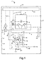
- FIG. 1 shows a household appliance 1 which comprises a housing 2 that contains all components of the appliance 1 to be described herein below and that is disposed in a suitable household ambient.
- the appliance 1 further comprises a drying chamber 3 that is provided in the form of a drum 3 rotatable around an axis of rotation 4.
- the drum 3 may be accessed by door 5, for charging with articles 6 to be dried in form of humid laundry 6. After being dried, the laundry 6 may be discharged through door 5 as well.
- first air conduit 7 For the purpose of drying the laundry 6, air is drawn into the appliance 1 through first air conduit 7 by a blower 8 that is operable by motor 9. To prevent dust and other dirt from contaminating the laundry 6, a filter 10 is provided in the first air conduit 7.
- Process air being drawn through the first air conduit 7 may be heated by electric heater 11.
- Electric heater 11 may be replaced by a heater operated by combustion of liquid or gaseous fuel in accordance with pertinent knowledge in the field of laundry dryers. In the present case, heater 11 is only an accessory component; the main share of the heating of the process air is accomplished by a heat pump 12, 13, 14, 15, 16, 17 which comprises a heat source 13 that forms a part of the first air conduit 7.
- the appliance 1 may be specified to be an exhaust-type laundry dryer, because process air that is conveyed through first air conduit 7 is guided in an open cycle, by being drawn to the appliance 1 through first air conduit 7, passing the articles 6 only once and being exhausted from the appliance 1 subsequently.
- the heat pump 12, 13, 14, 15, 16, 17 comprises besides the heat source 13 and the heat sink 14 that is coupled to a second air conduit 18, a heat transfer loop 12 containing a heat transfer fluid that is circulated by a compressor 15 driven by a compressor motor 16, and a nozzle 17.
- the heat transfer fluid which may be one of refrigerants R134a, R152a, R290, R407C, and R410A, will enter heat sink 14 in liquid form, to be evaporated by taking up heat from secondary air flowing through second air conduit 18 that the heat sink 14 belongs to.
- the heat transfer fluid After vaporization in the heat sink 14, the heat transfer fluid will flow through compressor 15, which will compress the heat transfer fluid to increase both its internal pressure and its temperature. Subsequently, the compressed heat transfer fluid will enter the heat source 13 and will be liquefied there, by releasing heat to the process air flowing through the first air conduit 7. Upon exiting the heat source 13, the heat transfer loop 12 will guide the liquefied heat transfer fluid through a nozzle 17, where the internal pressure of the liquid heat transfer fluid will be reduced.
- the nozzle 17 is to be understood as a representative for a plurality of suitable means including the nozzle 17, a capillary and a check valve. Downstream of the nozzle 17, the liquid heat transfer fluid with reduced internal pressure will be guided back to the heat sink 14 to complete its cycle through the heat transfer loop 12.
- process air flowing through the first air conduit 7 will be heated by heat extracted from secondary air flowing through the second air conduit 18. Accordingly, it is heat extracted from the ambient of the appliance 1 which is transferred into the process air for the purpose of heating to dry the laundry 6 contained in the drum 3.
- thermoelectric heat pumps and adsorption-type heat pumps may be mentioned.
- the second air conduit 18 has an inlet 19 that is not directly open to the appliance's 1 ambient. Rather, the inlet 19 is disposed within the housing 2, for air from inside the housing 2 to be drawn into the second air conduit 18.
- the housing 2 in turn has openings 20 in the form of small slits 20 or the like, which allow air from the ambient of the appliance 1 to enter the housing 2 and replace air that has been drawn into the second air conduit 18.
- heat sink 14 provides for a considerable cooling of the secondary air, condensation of humidity contained in such secondary air at the heat sink 14 must be expected. Accordingly and in conformance with pertinent knowledge, heat sink 14 is designed in such a way to allow for collection of such condensate and guiding such condensate to a condensate collector 21 for disposal after completion of a drying process.
- the second air conduit 18 comprises a cooler portion 22 that is arranged in operative connection to the compressor 15 and the compressor motor 16, to provide for some cooling of these components. By such cooling, accumulation of excess heat within the heat transfer loop 12 can be avoided, and stable operation of the heat transfer loop 12 assured.
- the first air conduit 7 and the second air conduit 18 are combined into a single exhaust conduit 23 downstream of the drum 3 and the cooler portion 22, respectively.
- Blower 8 is disposed within the exhaust conduit 23, to draw both the process air through the first air conduit 7 and the secondary air through the second air conduit 18 simultaneously.
- a temperature sensor 24 is placed at the heat sink 14 to detect a local temperature at the heat sink 14.
- a condensate sensor 25 is placed at the condensate collector 21 to allow for monitoring the generation of condensate at the heat sink 14.
- operation of the heat sink 14 may be controlled to avoid undesirably low temperatures at the heat sink 14 which might cause the formation of ice within the second air conduit 18.
- Temperature sensor 24 may be applied to monitor the temperature of the heat sink 14 directly, and the condensate sensor 25 may be used to monitor the operating condition of the heat sink 14 indirectly via an assessment of condensate produced during operation of the appliance 1. Details have been specified hereinabove.
- the sensors 24 and 25 shown are not meant to be the totality of sensors present in the appliance 1 and used to provide full control of its operation. Reference is made to pertinent knowledge for further sensors that may be used, in particular for sensors within the first air conduit 7, to monitor temperatures of the laundry 6 and thus control operation of the appliance 1.
- control is exercised by the control device 26 which is connected to all operative an controllable components of the appliance 1 through connection lines 27 for power supply or for reception of signals, as may be the case.
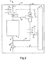
- FIG 2 shows a development of the embodiment from figure 1 , with only those components shown which are important in the present context.
- the second air conduit 18 draws air not from within the housing 2, but directly from the ambient of the appliance 1.
- the bypass conduit 28 that connects the first air conduit 7 and the second air conduit 18, and branches off from the first air conduit 7 downstream of the heat source 13, in particular even downstream of the heater 11 but upstream of the drum 3. Accordingly, the bypass conduit 28 allows conveying a fraction of the process air into the second air conduit 18 after heating up by the heat source 13 and the optional heater 11. This has the advantage that an undesirably low temperature at the heat sink 14 and monitored by temperature sensor 27, for example, can be avoided by rising the temperature of the secondary air at the heat sink 14.
- the heat sink 14 and neighbouring portions of the second air conduit 18 may be pre-heated during a heat up phase of the drying process, by operating the switching device 29 (exemplified as a flap 29) at the bypass conduit 28 to shut off the second air conduit 18 from its normal inlet 19, to draw only air which has been heated up by the heat source 13 and/or the heater 11.
- Such pre-heating may also be performed during a steady phase of a drying process; in such circumstance, normal operation of the heat pump 12, 13, 14, 15, 16, 17 should be discontinued to avoid further cooling at the heat sink 14, but heated air being still obtainable at least for a while by making use of residual heat contained in the heat source 13.
- the bypass conduit 28 can be very useful to avoid undesirable operating conditions at the heat sink 14.
- the embodiment shown in figure 2 incorporates as well a control device 26, to operate the various components mentioned here through appropriate connecting lines 27.
- FIG 3 shows an alternative embodiment of the appliance 1, which is characterized by keeping the first air conduit 7 and the second conduit 18 separate from each other. It should be noted that this embodiment may be further developed by incorporating a bypass conduit 28 and a switching device 29 as shown in Figure 2 .
- an exhaust hose 30 is connected to the outlet 31 of the first air conduit 7.
- process air that is exhausted from the first air conduit 7 will contain a considerable amount of humidity. Accordingly, such process air should not be exhausted into the immediate ambient of the appliance 1, to avoid precipitation of such humidity in that ambient.
- hose 30 should also be considered when placing an appliance 1 as shown in Figure 1 or Figure 2 within a building.
- the second air conduit 18 includes a separate second blower 32 to drive the secondary air there through. It should be noted that it may be desirable to drive both blowers 8 and 32 by a single blower motor 9 as shown in figure 1 . It should also be noted that the cooler portion 22 of the second air conduit 18 is embodied as an enclosure wherein the drive means 15 and 16 of the heat pump 12, 13, 14, 15, 16, 17, in particular the compressor 15 and the compressor motor 16, are disposed.
- appliances shown in detail herein are characterized by incorporating recovery of heat used in a drying process at least to a considerable extent, while retaining all pertinent positive features of normal exhaust-type appliances designed for drying.
Landscapes
- Engineering & Computer Science (AREA)
- Textile Engineering (AREA)
- Detail Structures Of Washing Machines And Dryers (AREA)
Priority Applications (7)
| Application Number | Priority Date | Filing Date | Title |
|---|---|---|---|
| EP07380356A EP2071069A1 (de) | 2007-12-11 | 2007-12-11 | Haushaltsgerät mit einer ersten Luftleitung und einer Wärmepumpe |
| EP08860807.0A EP2235249B1 (de) | 2007-12-11 | 2008-11-26 | Haushaltsgerät mit einer ersten luftleitung und einer wärmepumpe |
| PL08860807.0T PL2235249T3 (pl) | 2007-12-11 | 2008-11-26 | Urządzenie gospodarstwa domowego zawierające pierwszy przewód powietrzny i pompę ciepła |
| US12/746,188 US20100263225A1 (en) | 2007-12-11 | 2008-11-26 | Household appliance comprising a first air conduit and a heat pump |
| PCT/EP2008/066214 WO2009074455A1 (en) | 2007-12-11 | 2008-11-26 | Household appliance comprising a first air conduit and a heat pump |
| CN2008801202126A CN101896660B (zh) | 2007-12-11 | 2008-11-26 | 包括第一风管和热泵的家用电器 |
| EA201070688A EA017367B1 (ru) | 2007-12-11 | 2008-11-26 | Бытовой прибор, включающий воздуховод первичного воздуха и тепловой насос |
Applications Claiming Priority (1)
| Application Number | Priority Date | Filing Date | Title |
|---|---|---|---|
| EP07380356A EP2071069A1 (de) | 2007-12-11 | 2007-12-11 | Haushaltsgerät mit einer ersten Luftleitung und einer Wärmepumpe |
Publications (1)
| Publication Number | Publication Date |
|---|---|
| EP2071069A1 true EP2071069A1 (de) | 2009-06-17 |
Family
ID=39494656
Family Applications (1)
| Application Number | Title | Priority Date | Filing Date |
|---|---|---|---|
| EP07380356A Withdrawn EP2071069A1 (de) | 2007-12-11 | 2007-12-11 | Haushaltsgerät mit einer ersten Luftleitung und einer Wärmepumpe |
Country Status (1)
| Country | Link |
|---|---|
| EP (1) | EP2071069A1 (de) |
Cited By (2)
| Publication number | Priority date | Publication date | Assignee | Title |
|---|---|---|---|---|
| EP2690214A1 (de) * | 2012-07-27 | 2014-01-29 | Electrolux Home Products Corporation N.V. | Gerät zur Behandlung von Artikeln |
| US11186943B2 (en) | 2017-10-09 | 2021-11-30 | Whirlpool Corporation | Filter configured for being used in a machine for drying laundry and machine for drying laundry equipped with such a filter |
Citations (8)
| Publication number | Priority date | Publication date | Assignee | Title |
|---|---|---|---|---|
| DE4330456C1 (de) * | 1993-09-08 | 1995-03-16 | Blomberg Werke Gmbh | Wäschetrockner |
| EP0467188B1 (de) | 1990-07-19 | 2001-04-04 | BSH Bosch und Siemens Hausgeräte GmbH | Wäschetrockner mit einem Wärmepumpenkreis |
| DE19738735C2 (de) | 1997-09-04 | 2003-02-20 | Bsh Bosch Siemens Hausgeraete | Kondensationstrockner mit einem geschlossenen Trocknungsluftkreislauf |
| JP2004089415A (ja) | 2002-08-30 | 2004-03-25 | Matsushita Electric Ind Co Ltd | 衣類乾燥装置 |
| WO2006029953A1 (de) | 2004-09-13 | 2006-03-23 | BSH Bosch und Siemens Hausgeräte GmbH | Trocknungsverfahren für ein haushaltsgerät und haushaltsgerät zur durchführung des trocknungsverfahren |
| US20060117593A1 (en) * | 2004-12-07 | 2006-06-08 | Ahn Seung P | Clothes dryer with a dehumidifier |
| EP1672295A2 (de) | 2004-12-16 | 2006-06-21 | BSH Bosch und Siemens Hausgeräte GmbH | Klimaanlage |
| EP1672294A2 (de) | 2004-12-14 | 2006-06-21 | BSH Bosch und Siemens Hausgeräte GmbH | Klimaanlage |
-
2007
- 2007-12-11 EP EP07380356A patent/EP2071069A1/de not_active Withdrawn
Patent Citations (8)
| Publication number | Priority date | Publication date | Assignee | Title |
|---|---|---|---|---|
| EP0467188B1 (de) | 1990-07-19 | 2001-04-04 | BSH Bosch und Siemens Hausgeräte GmbH | Wäschetrockner mit einem Wärmepumpenkreis |
| DE4330456C1 (de) * | 1993-09-08 | 1995-03-16 | Blomberg Werke Gmbh | Wäschetrockner |
| DE19738735C2 (de) | 1997-09-04 | 2003-02-20 | Bsh Bosch Siemens Hausgeraete | Kondensationstrockner mit einem geschlossenen Trocknungsluftkreislauf |
| JP2004089415A (ja) | 2002-08-30 | 2004-03-25 | Matsushita Electric Ind Co Ltd | 衣類乾燥装置 |
| WO2006029953A1 (de) | 2004-09-13 | 2006-03-23 | BSH Bosch und Siemens Hausgeräte GmbH | Trocknungsverfahren für ein haushaltsgerät und haushaltsgerät zur durchführung des trocknungsverfahren |
| US20060117593A1 (en) * | 2004-12-07 | 2006-06-08 | Ahn Seung P | Clothes dryer with a dehumidifier |
| EP1672294A2 (de) | 2004-12-14 | 2006-06-21 | BSH Bosch und Siemens Hausgeräte GmbH | Klimaanlage |
| EP1672295A2 (de) | 2004-12-16 | 2006-06-21 | BSH Bosch und Siemens Hausgeräte GmbH | Klimaanlage |
Cited By (4)
| Publication number | Priority date | Publication date | Assignee | Title |
|---|---|---|---|---|
| EP2690214A1 (de) * | 2012-07-27 | 2014-01-29 | Electrolux Home Products Corporation N.V. | Gerät zur Behandlung von Artikeln |
| WO2014016426A3 (en) * | 2012-07-27 | 2014-04-03 | Electrolux Home Products Corporation N.V. | Appliance for treating articles |
| US11186943B2 (en) | 2017-10-09 | 2021-11-30 | Whirlpool Corporation | Filter configured for being used in a machine for drying laundry and machine for drying laundry equipped with such a filter |
| US11761141B2 (en) | 2017-10-09 | 2023-09-19 | Whirlpool Corporation | Filter configured for being used in a machine for drying laundry and machine for drying laundry equipped with such a filter |
Similar Documents
| Publication | Publication Date | Title |
|---|---|---|
| EP2235249B1 (de) | Haushaltsgerät mit einer ersten luftleitung und einer wärmepumpe | |
| US8356423B2 (en) | Household appliance containing a heat transfer fluid | |
| EP2132370B1 (de) | Haushaltsgerät mit wärmepumpe | |
| EP2640885B1 (de) | Maschine mit wärmepumpe und zugehöriger verfahrenssatz | |
| CN101939479B (zh) | 包括热泵和加热器的滚筒干衣机及其操作方法 | |
| EP2212463B1 (de) | Haushaltsgerät mit wärmepumpeneinheit und mittel zur kühlung einer komponente davon | |
| US20090139107A1 (en) | Exhaust air dryer with a heat pump and a first fan | |
| US20100132216A1 (en) | Dryer with a heat pump and an electrical heating element and also a method for its operation | |
| EA014949B1 (ru) | Конденсационная сушилка с тепловым насосом и способ её работы | |
| WO2012110353A2 (en) | A heat pump laundry dryer | |
| EP2060671B1 (de) | Haushaltswäschetrockner | |
| JP2000304449A (ja) | エアサイクル式乾燥システム | |
| EP2071069A1 (de) | Haushaltsgerät mit einer ersten Luftleitung und einer Wärmepumpe | |
| US20040255394A1 (en) | Spin cycle methodology and article drying apparatus | |
| JP2004089413A (ja) | 衣類乾燥装置 | |
| EP2147999A1 (de) | Haushaltswäschetrockner | |
| EP2412868A1 (de) | Maschine und Verfahren zum Trocknen von feuchten Artikeln mit Überhitzung eines Kühlmittels | |
| CN112760901A (zh) | 家用洗衣-干衣机 | |
| CN113756068A (zh) | 具有包括膨胀装置的热泵的家用器具、特别是洗涤物烘干机 |
Legal Events
| Date | Code | Title | Description |
|---|---|---|---|
| PUAI | Public reference made under article 153(3) epc to a published international application that has entered the european phase |
Free format text: ORIGINAL CODE: 0009012 |
|
| AK | Designated contracting states |
Kind code of ref document: A1 Designated state(s): AT BE BG CH CY CZ DE DK EE ES FI FR GB GR HU IE IS IT LI LT LU LV MC MT NL PL PT RO SE SI SK TR |
|
| AX | Request for extension of the european patent |
Extension state: AL BA HR MK RS |
|
| AKX | Designation fees paid | ||
| REG | Reference to a national code |
Ref country code: DE Ref legal event code: 8566 |
|
| STAA | Information on the status of an ep patent application or granted ep patent |
Free format text: STATUS: THE APPLICATION IS DEEMED TO BE WITHDRAWN |
|
| 18D | Application deemed to be withdrawn |
Effective date: 20091218 |