EP2070874A1 - Water purification device - Google Patents
Water purification device Download PDFInfo
- Publication number
- EP2070874A1 EP2070874A1 EP07405353A EP07405353A EP2070874A1 EP 2070874 A1 EP2070874 A1 EP 2070874A1 EP 07405353 A EP07405353 A EP 07405353A EP 07405353 A EP07405353 A EP 07405353A EP 2070874 A1 EP2070874 A1 EP 2070874A1
- Authority
- EP
- European Patent Office
- Prior art keywords
- water collecting
- collecting device
- water
- expansion means
- volume
- Prior art date
- Legal status (The legal status is an assumption and is not a legal conclusion. Google has not performed a legal analysis and makes no representation as to the accuracy of the status listed.)
- Withdrawn
Links
- XLYOFNOQVPJJNP-UHFFFAOYSA-N water Substances O XLYOFNOQVPJJNP-UHFFFAOYSA-N 0.000 title claims abstract description 206
- 238000000746 purification Methods 0.000 title claims abstract description 17
- 239000012528 membrane Substances 0.000 claims abstract description 16
- 239000000463 material Substances 0.000 claims description 15
- 238000000034 method Methods 0.000 claims description 4
- 238000005452 bending Methods 0.000 claims description 3
- 230000000694 effects Effects 0.000 claims description 3
- 230000008859 change Effects 0.000 claims description 2
- 238000001914 filtration Methods 0.000 description 8
- 238000003466 welding Methods 0.000 description 5
- 239000010410 layer Substances 0.000 description 4
- 230000007246 mechanism Effects 0.000 description 4
- 235000015097 nutrients Nutrition 0.000 description 3
- 239000004033 plastic Substances 0.000 description 3
- 239000000654 additive Substances 0.000 description 2
- 239000000356 contaminant Substances 0.000 description 2
- 239000013013 elastic material Substances 0.000 description 2
- 230000005226 mechanical processes and functions Effects 0.000 description 2
- 239000000203 mixture Substances 0.000 description 2
- 239000011148 porous material Substances 0.000 description 2
- 239000000126 substance Substances 0.000 description 2
- 241000894006 Bacteria Species 0.000 description 1
- RFSUNEUAIZKAJO-ARQDHWQXSA-N Fructose Chemical compound OC[C@H]1O[C@](O)(CO)[C@@H](O)[C@@H]1O RFSUNEUAIZKAJO-ARQDHWQXSA-N 0.000 description 1
- 229930091371 Fructose Natural products 0.000 description 1
- 239000005715 Fructose Substances 0.000 description 1
- 241000700605 Viruses Species 0.000 description 1
- 230000009471 action Effects 0.000 description 1
- 239000000919 ceramic Substances 0.000 description 1
- 239000003610 charcoal Substances 0.000 description 1
- 238000004140 cleaning Methods 0.000 description 1
- 230000006835 compression Effects 0.000 description 1
- 238000007906 compression Methods 0.000 description 1
- 230000001419 dependent effect Effects 0.000 description 1
- 238000010612 desalination reaction Methods 0.000 description 1
- 238000004146 energy storage Methods 0.000 description 1
- 230000002401 inhibitory effect Effects 0.000 description 1
- 239000002184 metal Substances 0.000 description 1
- -1 nourishment Chemical class 0.000 description 1
- 235000016709 nutrition Nutrition 0.000 description 1
- 230000035764 nutrition Effects 0.000 description 1
- 230000003204 osmotic effect Effects 0.000 description 1
- 239000002245 particle Substances 0.000 description 1
- 239000002985 plastic film Substances 0.000 description 1
- 230000008569 process Effects 0.000 description 1
- 230000002787 reinforcement Effects 0.000 description 1
- 239000013535 sea water Substances 0.000 description 1
- 238000007789 sealing Methods 0.000 description 1
- 238000010008 shearing Methods 0.000 description 1
- 239000002356 single layer Substances 0.000 description 1
- 235000000346 sugar Nutrition 0.000 description 1
- 150000008163 sugars Chemical class 0.000 description 1
- 235000013343 vitamin Nutrition 0.000 description 1
- 229940088594 vitamin Drugs 0.000 description 1
- 229930003231 vitamin Natural products 0.000 description 1
- 239000011782 vitamin Substances 0.000 description 1
Images


Classifications
-
- C—CHEMISTRY; METALLURGY
- C02—TREATMENT OF WATER, WASTE WATER, SEWAGE, OR SLUDGE
- C02F—TREATMENT OF WATER, WASTE WATER, SEWAGE, OR SLUDGE
- C02F1/00—Treatment of water, waste water, or sewage
- C02F1/001—Processes for the treatment of water whereby the filtration technique is of importance
- C02F1/002—Processes for the treatment of water whereby the filtration technique is of importance using small portable filters for producing potable water, e.g. personal travel or emergency equipment, survival kits, combat gear
-
- B—PERFORMING OPERATIONS; TRANSPORTING
- B01—PHYSICAL OR CHEMICAL PROCESSES OR APPARATUS IN GENERAL
- B01D—SEPARATION
- B01D29/00—Filters with filtering elements stationary during filtration, e.g. pressure or suction filters, not covered by groups B01D24/00 - B01D27/00; Filtering elements therefor
- B01D29/11—Filters with filtering elements stationary during filtration, e.g. pressure or suction filters, not covered by groups B01D24/00 - B01D27/00; Filtering elements therefor with bag, cage, hose, tube, sleeve or like filtering elements
- B01D29/117—Filters with filtering elements stationary during filtration, e.g. pressure or suction filters, not covered by groups B01D24/00 - B01D27/00; Filtering elements therefor with bag, cage, hose, tube, sleeve or like filtering elements arranged for outward flow filtration
-
- B—PERFORMING OPERATIONS; TRANSPORTING
- B01—PHYSICAL OR CHEMICAL PROCESSES OR APPARATUS IN GENERAL
- B01D—SEPARATION
- B01D61/00—Processes of separation using semi-permeable membranes, e.g. dialysis, osmosis or ultrafiltration; Apparatus, accessories or auxiliary operations specially adapted therefor
- B01D61/14—Ultrafiltration; Microfiltration
- B01D61/18—Apparatus therefor
-
- B—PERFORMING OPERATIONS; TRANSPORTING
- B01—PHYSICAL OR CHEMICAL PROCESSES OR APPARATUS IN GENERAL
- B01D—SEPARATION
- B01D63/00—Apparatus in general for separation processes using semi-permeable membranes
-
- B—PERFORMING OPERATIONS; TRANSPORTING
- B01—PHYSICAL OR CHEMICAL PROCESSES OR APPARATUS IN GENERAL
- B01D—SEPARATION
- B01D2313/00—Details relating to membrane modules or apparatus
- B01D2313/18—Specific valves
-
- B—PERFORMING OPERATIONS; TRANSPORTING
- B01—PHYSICAL OR CHEMICAL PROCESSES OR APPARATUS IN GENERAL
- B01D—SEPARATION
- B01D2313/00—Details relating to membrane modules or apparatus
- B01D2313/24—Specific pressurizing or depressurizing means
-
- C—CHEMISTRY; METALLURGY
- C02—TREATMENT OF WATER, WASTE WATER, SEWAGE, OR SLUDGE
- C02F—TREATMENT OF WATER, WASTE WATER, SEWAGE, OR SLUDGE
- C02F1/00—Treatment of water, waste water, or sewage
- C02F1/44—Treatment of water, waste water, or sewage by dialysis, osmosis or reverse osmosis
Definitions
- the invention relates to the field of water purification devices, and in particular to a low-cost, small scale purification device as described in the preamble of claim 1.
- US 4,879,030 describes a water purification and emergency nutrition package.
- the package comprises a compartment having a semipermeable membrane which allows it to desalinate water, and a compartment comprising a mixture of water-soluble nutrients such as fructose. Once a minimum amount of water has entered the package, osmotic pressure caused by the water-soluble nutrients drives the further transfer of water through the semipermeable membrane. Applicability of the device is limited in that it can be used only once, in that it does not provide water alone, but rather a mixture of water and sugars, i.e. nourishment, and in that it is focused on the desalination of sea water.
- the water purification device comprises an expandable water collecting device having a variable volume, wherein at least part of the surface of the water collecting device comprises a filter area, the filter area being permeable to water and allowing water to enter the water collecting device when the filter area is submerged in water.
- the device further comprises a mechanically driven expansion means, for exerting a force for increasing the volume of the water collecting device and thereby drawing water through the filter area into the water collecting device.
- the water collecting device is first compressed, that is, brought into a reduced volume or, ideally, a minimum volume configuration. This is done e.g. by flattening the water collecting device, counteracting the force of the expansion means. While flattening the water collecting device, a clean water outlet should be opened, allowing air trapped in the water collecting device to escape. For practical reasons, the water collecting device will preferably also be delivered and stored in a reduced volume configuration.
- the water collecting device is then submerged in water that requires filtering before consumption, i.e. in a well or a river or the like.
- the water collecting device may also be left to rest on the water, with the filter area being at least partially submerged, i.e. in contact with the water.
- the expansion means is then released, allowing the water collecting device to expand, whereby water enters the water collecting device through the filter membrane.
- the water collecting device is removed from the water, and the filtered water is drained from the water collecting device through an outlet.
- the water collecting device is extremely simple to use.
- a retainer or restraint is arranged to keep the water collecting device in the reduced volume configuration until it is submerged. This can be done, for example, by a bracket or clip reaching around the water collecting device and holding it in a compressed, reduced volume configuration. The bracket is slid off or pulled away after submerging the water collecting device. Alternatively, the water collecting device may be held in the reduced volume configuration by hand until it is submerged.
- the water collecting device comprises an escape valve, e.g. molded from elastic plastic. This allows to manually submerge the water collecting device and then to manually compress the water collecting device while holding it under water, forcing out remaining air through the escape valve.
- the water collecting device preferably further comprises an outlet for removing clean water accumulated in the water collecting device; alternatively, the outlet may be identical to the escape valve, since it is only necessary to empty the water collecting device through the outlet valve, whereas the water collecting device is filled through its filter surface. The outlet may be reclosable.
- the water collecting device preferably comprises a means for attaching a weight or for being attached to an external support.
- Said means can be an eyelet or grommet, or a piece of string or band attached to the water collecting device.
- the band may be made of the same material as the water collecting device, e.g. a strip of material that is partially cut from a sheet constituting the water collecting device.
- the water collecting device comprises holding elements such as straps. These straps may be attached in, or close to, regions which are pushed away from each other by the expansion means. In consequence, an expansion force can be generated or increased by manually pulling the holding elements.
- the water collecting device is preferably made of a flexible sheet material shaped to form a container (except for the fact that the container walls are, at least in the filter areas, permeable).
- the water collecting device comprises two sections of a filter membrane material that are joined in a watertight manner along edges of the sections, forming in the expanded state of the water collecting device a substantially pillow-shaped bag.
- the water collecting device may be formed by a cylindrical filter surface, which is expanded by a helical spring inside the water collecting device. A multitude of other geometrical shapes which can be folded and unfolded and in this manner exhibit two different volumes may be used for the water collecting device.
- a substantial part of the entire surface of the water collecting device is made of a material serving as the filter.
- at least a quarter or at least half the surface area of the water collecting device is made of said filtering material.
- the filter is permeable to water but impermeable to a group of water contaminants, reducing the concentration of contaminants in the filtered water.
- the filter may be a simple mechanical filter, inhibiting passage of particles exceeding a predetermined size, but may also be chemically treated or coated or comprise multiple layers implementing different water treatment functions and mechanical functions.
- the filter pore size is preferably smaller than one micrometer, and in particular smaller than 0.5 or 0.1 micrometers or less, for filtering out bacteria and preferably also viruses.
- the filter, and the water collecting device as a whole are preferably made of a biodegradable material.
- the water treatment and mechanical functions implemented by said multiple layers are, for example: fine pore filtering, chemical treatment, charcoal filter, stiffening the container walls of the water collecting device, mechanical reinforcement, or mechanical protection.
- Each of these functions may be implemented by a dedicated layer, or one or more functions may be implemented by a single layer.
- the layer or layers may be treated by welding them along welding lines or in a plurality of welding points. This serves to reinforce, join, and/or to stiffen the layers.
- the expansion means when the water collecting device is in a first configuration, comprising a reduced volume, the expansion means comprises stored energy, and release of said stored energy causes the volume of the water collecting device to increase.
- the expansion means comprises, in a loaded state, potential spring energy, which is used to expand the water collecting device from a substantially empty, low volume state, to an unloaded or released state in which it is filled with water, and in which the expansion means is in a state of minimal energy.
- the expansion means is arranged inside the water collecting device.
- the first configuration corresponds to an essentially flat configuration of the expansion means
- the increase of volume of the water collecting device corresponds to the expansion means assuming a three-dimensional configuration
- the water collecting device In the reduced volume state, the water collecting device is well suited for efficient storage and transport.
- the water collecting device will preferably be produced to be stored in a reduced volume state, e.g. pre-folded, with the faces of the water collecting device being folded inwards or outwards.
- the expansion means preferably comprises at least one resilient element which releases stored energy by deforming, i.e. by changing its shape, in particular by at least one of the following: bending, unbending, expanding, contracting.
- the expansion means preferably comprises one or more struts that form a frame supporting the water collecting device and transferring and distributing the forces for expanding the water collecting device to the water collecting device surface.
- the struts themselves constitute resilient elements for releasing stored energy and/or are arranged in co-operation with separate resilient elements for releasing stored energy.
- a strut may, for example, be an elongated, stick-like body, or a section of a flat but elastic sheet of material, or a perforated sheet of elastic material.
- the expansion means comprises, in addition to the struts, separate resilient elements, these resilient elements may be arranged, in order to increase the volume of the water collecting device:
- the expansion means may comprise two flat, star-shaped structures, e.g. made of a plastic sheet, arranged inside a pillow-like bag or container and pressed apart by a spring.
- the expansion means comprises a frame of flexible wires that can be bent into a flat shape and then expands to a three-dimensional shape.
- the energy stored in the resilient elements may be stored by deforming the elements, or by providing, as part of the elements, airtight volumes which can be inflated. Inflating the volumes causes them to expand, providing a resilient element.
- the struts may be formed as inflatable volumes.
- the struts are inflated, e.g. with a simple pump, establishing the tension which causes the struts to expand the water collecting device.
- driving the expansion mechanically also includes the use of such pneumatic energy storage, which is converted to mechanical forces driving the expansion.
- the energy for expanding the water collecting device is stored by a resilient element which has a porous or sponge-like structure.
- a resilient element which has a porous or sponge-like structure.
- Such an element also may comprise mechanical water filtering and/or chemical purification functions.
- the expansion means is manually activated, for example by directly driving the expansion, or by storing energy in a resilient element, e.g. by manually deforming (compressing or loading) a spring or another elastic element. The elastic element then gradually relaxes while the water collecting device expands.
- the water collecting device comprises a supply of alimentary additives such as nutrients or vitamins.
- the additives are dissolved or diluted or mixed with the filtered water collecting in the water collecting device.
- the purification device comprises a watertight outer envelope in which the water collecting device may be arranged.
- the outer envelope may be welded or otherwise attached to the water collecting device, or may be a loose component. If the outer envelope is attached to the water collecting device, it may be either put over the water collecting container or pulled back to expose the water collecting device for filtering (when immersed in water) or for cleaning the filter area.
- the outer envelope is arranged to contain the water collecting device, it can preferably be closed around the water collecting device, e.g. by a minigrip®-like sealing mechanism.
- the filtration device is not submerged as a whole, but the outer envelope is filled with water, and the water collecting device expands within the outer envelope, drawing in the water from the outer envelope.
- the volume of the water collecting device is preferably in the range of 0.5 liters to 2 liters, with its dimensions being, for example, 150 by 80 by 40 millimeters or more.
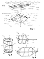
- FIG. 1 schematically shows the use of a water collecting device 1 for water purification according to the invention.
- the water collecting device 1 comprises a filter membrane 2, which constitutes the walls of the water collecting device 1 itself, and a frame made up of struts 3.
- a resilient element 4 such as a spring, is arranged to push opposing sides of the frame apart, increasing the volume of the water collecting device 1.
- An outlet 6 serves to extract the filtered water.
- the outlet 6 is either openable and reclosable, or has a valve function which allows water and air to exit the water collecting device when pressure is applied to the water collecting device.
- optional straps 14 for manually driving or assisting in the expansion of the device.
- the spring 4 When the water collecting device 1 is submerged, the spring 4 is released. The spring 4 gradually increases the volume of the water collecting device 1, as water flows though the filter membrane 2 into the water collecting device 1. When the maximum volume has been reached (bottom part of Figure 1 ), the water collecting device 1 can be retrieved and emptied by means of the outlet 6.
- the water collecting device 1 should be entirely submerged in order to prevent air from being sucked in through the filter membrane 2.
- the filter membrane 2 may be welded together, for example, at front and back end sections of the water collecting device 1.
- One of the welds shown comprises an eyelet 8 for attaching the device to a weight or an external support (not shown) for submerging the water collecting device 1.
- FIG. 2 shows an expansion means of a first embodiment of the invention in a transport and storage configuration.
- the expansion means comprises two support structures 7 comprising several struts 3, and two O-shaped springs 9 serving as resilient elements 4.
- the support structures 7 themselves may also exhibit a certain resilience.
- Both the support structures 7 and the O-shaped springs 9 are made of a plastic material, preferably from sheets of material, such that they exhibit a certain stiffness within the plane of the sheet, and a comparatively larger elasticity in other directions.
- the O-shaped springs 9 preferably are in an unloaded state, which prevents them from losing their resilience.
- the O-shaped springs 9 and the support structures 7 are folded flat, preferably inside a corresponding water collecting device.
- the O-shaped springs 9 and support structures 7 are unfolded, whereby the O-shaped springs 9 snap and/or lock into a position in which they press the support structure 7 away from each other.
- Figure 3 shows said expansion means in the resulting state, that is, in a ready-to-use configuration.
- This snapping action is accomplished, e.g. by pulling flat sections of the support structures 7 and the O-shaped springs 9 against one another by means of rubber bands 12.
- said flat sections of the support structures 7 and the O-shaped springs 9 are at right angles to one another and the rubber bands 12 going around both of them are elongated.
- said flat sections lie flat on each other and the rubber bands 12 are shortened.
- FIG. 4 shows said expansion means in a ready-to-use configuration inside the corresponding water collecting device. Also shown are optional straps 14 for manually driving or assisting in the expansion of the device.
- Figure 5 shows a frame of a further embodiment of the invention in a reduced volume configuration.
- the frame is constituted of a set of struts 3 made of a flexible and elastic material, preferably metal or a plastic that is not subject to material fatigue.
- the frame is compressed by forcing the two middle struts 3 together.
- Figure 6 shows said frame in a released or expanded configuration.
- Figure 7 shows said frame inside the corresponding water collecting device 1, again in the expanded configuration.
- the frame defined by the struts 3 is arranged inside the volume formed by the membrane 2, which may be welded together at the edges by welding seams 18. If the volume is expanded by the resilience of the struts 3, then no further expansion means is mandatory, otherwise, a spring or other expanding device for pushing selected struts 3 apart may be arranged inside the volume, as in the embodiment of Figure 1 .
- Straps 14 are attached to the membrane and preferably also to struts 3.
- An optional watertight outer envelope 16 may be attached to the device 1, arranged in an extended position as shown in the figure.
- the outer envelope 16 may be folded around the collecting device 1 (as indicated by arrows) and then closed by a closing means or closure 17, e.g. a minigrip® seal. Such an outer envelope 16 may of course be added to any of the other embodiments as well. The outer envelope 16 may also be detached from the device 1.
- Figure 8 shows a cylindrical water collecting device 1 comprising a helical spring 10 in an expanded state.
- the helical spring 10 is compressed to an essentially planar configuration, and the filter membrane 2 folds accordingly.
- Figure 9 shows a water collecting device 1 with a manually operable expansion means in a half-filled state and a full (maximum volume) state.
- the device comprises rigid rings 11 attached to the inside of the (filter membrane) surface 2 of the device 1. When pulled apart by the expansion means, the rings 11 define a cylindrical volume which is spanned by the membrane 2.
- the mechanically driven expansion means is constituted by a rod 12 which is guided through a cap 13 attached to a first end of the device, and pushes an opposing end of the device away from the first end.
- a resilient element such as a spring, e.g. an O-shaped spring 9, may be arranged to be compressed by the rod 12 when the rod 12 is pushed into the device.
- the spring 9 expands gradually as water enters the device through the filter 2.
- the rod 12 can be pushed in again, repeating the process until the device 1 is full.
- part or all of the surface of the collecting device 1 is elastic, and is tensioned when the rod 12 is pushed into the device.
- the cap 13 preferably comprises a screw mechanism or a ratchet mechanism which prevents the rod 12 from sliding out after being pushed in. If a screw mechanism is used, then one part of the cap can be turned with respect to the other one, or the rod can be turned with respect to the rest of the device in order to create the linear movement of the rod with respect to the cap when expanding the device 1.
- the outlet, optional straps etc. are omitted in Figure 9 for clarity.
Landscapes
- Chemical & Material Sciences (AREA)
- Engineering & Computer Science (AREA)
- Water Supply & Treatment (AREA)
- Chemical Kinetics & Catalysis (AREA)
- Life Sciences & Earth Sciences (AREA)
- Hydrology & Water Resources (AREA)
- Environmental & Geological Engineering (AREA)
- Organic Chemistry (AREA)
- Filtration Of Liquid (AREA)
- Separation Using Semi-Permeable Membranes (AREA)
Abstract
A water purification device comprises an expandable water collecting device (1) having a variable volume, wherein at least part of the surface of the water collecting device comprises a filter area (2), the filter area (2) being permeable to water and allowing water to enter the water collecting device (1) when the filter area (2) is submerged in water. The device further comprises a mechanically driven expansion means (3, 4) for exerting a force for increasing the volume of the water collecting device (1) and thereby drawing water through the filter area into the water collecting device (1). In use, the water collecting device (1) is submerged and the expansion means is released, drawing water into the water collecting device (1) through the filter membrane (2).
Description
- The invention relates to the field of water purification devices, and in particular to a low-cost, small scale purification device as described in the preamble of claim 1.
- Access to clean water is an essential human necessity. In developing countries, in emergency situations, and simply for outdoor activities, there is a need for simple, lightweight, and cheap water purification devices. Numerous filtering devices, e.g. using ceramic filters, multiple water collecting devices with intervening filters etc. are known.
-
US 4,879,030 describes a water purification and emergency nutrition package. The package comprises a compartment having a semipermeable membrane which allows it to desalinate water, and a compartment comprising a mixture of water-soluble nutrients such as fructose. Once a minimum amount of water has entered the package, osmotic pressure caused by the water-soluble nutrients drives the further transfer of water through the semipermeable membrane. Applicability of the device is limited in that it can be used only once, in that it does not provide water alone, but rather a mixture of water and sugars, i.e. nourishment, and in that it is focused on the desalination of sea water. - It is therefore an object of the invention to create a water purification device of the type mentioned initially, which overcomes the disadvantages mentioned above.
- These objects are achieved by a water purification device according to claim 1.
- The water purification device comprises an expandable water collecting device having a variable volume, wherein at least part of the surface of the water collecting device comprises a filter area, the filter area being permeable to water and allowing water to enter the water collecting device when the filter area is submerged in water. The device further comprises a mechanically driven expansion means, for exerting a force for increasing the volume of the water collecting device and thereby drawing water through the filter area into the water collecting device.
- For use, the water collecting device is first compressed, that is, brought into a reduced volume or, ideally, a minimum volume configuration. This is done e.g. by flattening the water collecting device, counteracting the force of the expansion means. While flattening the water collecting device, a clean water outlet should be opened, allowing air trapped in the water collecting device to escape. For practical reasons, the water collecting device will preferably also be delivered and stored in a reduced volume configuration. The water collecting device is then submerged in water that requires filtering before consumption, i.e. in a well or a river or the like. The water collecting device may also be left to rest on the water, with the filter area being at least partially submerged, i.e. in contact with the water. The expansion means is then released, allowing the water collecting device to expand, whereby water enters the water collecting device through the filter membrane. When a predetermined amount of filtered water has accumulated inside the water collecting device, the water collecting device is removed from the water, and the filtered water is drained from the water collecting device through an outlet. The water collecting device is extremely simple to use.
- In situations in which air flows through the filter area rather rapidly, the water collecting device may expand before being submerged, by taking in air through the filter. Therefore, in a preferred embodiment of the invention, a retainer or restraint is arranged to keep the water collecting device in the reduced volume configuration until it is submerged. This can be done, for example, by a bracket or clip reaching around the water collecting device and holding it in a compressed, reduced volume configuration. The bracket is slid off or pulled away after submerging the water collecting device. Alternatively, the water collecting device may be held in the reduced volume configuration by hand until it is submerged.
- In a further preferred embodiment of the invention, the water collecting device comprises an escape valve, e.g. molded from elastic plastic. This allows to manually submerge the water collecting device and then to manually compress the water collecting device while holding it under water, forcing out remaining air through the escape valve. The water collecting device preferably further comprises an outlet for removing clean water accumulated in the water collecting device; alternatively, the outlet may be identical to the escape valve, since it is only necessary to empty the water collecting device through the outlet valve, whereas the water collecting device is filled through its filter surface. The outlet may be reclosable.
- In order to ease the submerging, in case some air is trapped in the water collecting device, the water collecting device preferably comprises a means for attaching a weight or for being attached to an external support. Said means can be an eyelet or grommet, or a piece of string or band attached to the water collecting device. The band may be made of the same material as the water collecting device, e.g. a strip of material that is partially cut from a sheet constituting the water collecting device.
- In a further preferred embodiment of the invention, the water collecting device comprises holding elements such as straps. These straps may be attached in, or close to, regions which are pushed away from each other by the expansion means. In consequence, an expansion force can be generated or increased by manually pulling the holding elements.
The water collecting device is preferably made of a flexible sheet material shaped to form a container (except for the fact that the container walls are, at least in the filter areas, permeable). For example, the water collecting device comprises two sections of a filter membrane material that are joined in a watertight manner along edges of the sections, forming in the expanded state of the water collecting device a substantially pillow-shaped bag. Or, the water collecting device may be formed by a cylindrical filter surface, which is expanded by a helical spring inside the water collecting device. A multitude of other geometrical shapes which can be folded and unfolded and in this manner exhibit two different volumes may be used for the water collecting device. - In a preferred embodiment of the invention, a substantial part of the entire surface of the water collecting device is made of a material serving as the filter. In other preferred embodiments, at least a quarter or at least half the surface area of the water collecting device is made of said filtering material. The filter is permeable to water but impermeable to a group of water contaminants, reducing the concentration of contaminants in the filtered water. The filter may be a simple mechanical filter, inhibiting passage of particles exceeding a predetermined size, but may also be chemically treated or coated or comprise multiple layers implementing different water treatment functions and mechanical functions. The filter pore size is preferably smaller than one micrometer, and in particular smaller than 0.5 or 0.1 micrometers or less, for filtering out bacteria and preferably also viruses. The filter, and the water collecting device as a whole, are preferably made of a biodegradable material.
- The water treatment and mechanical functions implemented by said multiple layers are, for example: fine pore filtering, chemical treatment, charcoal filter, stiffening the container walls of the water collecting device, mechanical reinforcement, or mechanical protection. Each of these functions may be implemented by a dedicated layer, or one or more functions may be implemented by a single layer.
- In further embodiments of the invention, the layer or layers may be treated by welding them along welding lines or in a plurality of welding points. This serves to reinforce, join, and/or to stiffen the layers.
- In a further preferred embodiment of the invention, when the water collecting device is in a first configuration, comprising a reduced volume, the expansion means comprises stored energy, and release of said stored energy causes the volume of the water collecting device to increase. In other words; the expansion means comprises, in a loaded state, potential spring energy, which is used to expand the water collecting device from a substantially empty, low volume state, to an unloaded or released state in which it is filled with water, and in which the expansion means is in a state of minimal energy. In a further preferred embodiment of the invention, the expansion means is arranged inside the water collecting device.
- In a preferred embodiment of the invention, the first configuration corresponds to an essentially flat configuration of the expansion means, and the increase of volume of the water collecting device corresponds to the expansion means assuming a three-dimensional configuration.
- In the reduced volume state, the water collecting device is well suited for efficient storage and transport. Thus, the water collecting device will preferably be produced to be stored in a reduced volume state, e.g. pre-folded, with the faces of the water collecting device being folded inwards or outwards.
- The expansion means preferably comprises at least one resilient element which releases stored energy by deforming, i.e. by changing its shape, in particular by at least one of the following: bending, unbending, expanding, contracting.
- The expansion means preferably comprises one or more struts that form a frame supporting the water collecting device and transferring and distributing the forces for expanding the water collecting device to the water collecting device surface. The struts themselves constitute resilient elements for releasing stored energy and/or are arranged in co-operation with separate resilient elements for releasing stored energy. A strut may, for example, be an elongated, stick-like body, or a section of a flat but elastic sheet of material, or a perforated sheet of elastic material.
- In the case in which the expansion means comprises, in addition to the struts, separate resilient elements, these resilient elements may be arranged, in order to increase the volume of the water collecting device:
- to effect a change of angle between adjacent struts; or
- to push sections of the struts away from each other; or
- to pull sections of the struts towards each other.
- For example, the expansion means may comprise two flat, star-shaped structures, e.g. made of a plastic sheet, arranged inside a pillow-like bag or container and pressed apart by a spring. Or, in another preferred embodiment of the invention, the expansion means comprises a frame of flexible wires that can be bent into a flat shape and then expands to a three-dimensional shape.
- The energy stored in the resilient elements may be stored by deforming the elements, or by providing, as part of the elements, airtight volumes which can be inflated. Inflating the volumes causes them to expand, providing a resilient element. For example, the struts may be formed as inflatable volumes. In order to use the purification device, the struts are inflated, e.g. with a simple pump, establishing the tension which causes the struts to expand the water collecting device. Thus, driving the expansion mechanically also includes the use of such pneumatic energy storage, which is converted to mechanical forces driving the expansion.
- In another preferred embodiment of the invention, the energy for expanding the water collecting device is stored by a resilient element which has a porous or sponge-like structure. Such an element also may comprise mechanical water filtering and/or chemical purification functions.
- In yet a further preferred embodiment of the invention, the expansion means is manually activated, for example by directly driving the expansion, or by storing energy in a resilient element, e.g. by manually deforming (compressing or loading) a spring or another elastic element. The elastic element then gradually relaxes while the water collecting device expands.
- In a further preferred embodiment of the invention, the water collecting device comprises a supply of alimentary additives such as nutrients or vitamins. The additives are dissolved or diluted or mixed with the filtered water collecting in the water collecting device.
- In a further preferred embodiment of the invention, the purification device comprises a watertight outer envelope in which the water collecting device may be arranged. The outer envelope may be welded or otherwise attached to the water collecting device, or may be a loose component. If the outer envelope is attached to the water collecting device, it may be either put over the water collecting container or pulled back to expose the water collecting device for filtering (when immersed in water) or for cleaning the filter area. When the outer envelope is arranged to contain the water collecting device, it can preferably be closed around the water collecting device, e.g. by a minigrip®-like sealing mechanism. In another application of the invention, the filtration device is not submerged as a whole, but the outer envelope is filled with water, and the water collecting device expands within the outer envelope, drawing in the water from the outer envelope.
- The volume of the water collecting device is preferably in the range of 0.5 liters to 2 liters, with its dimensions being, for example, 150 by 80 by 40 millimeters or more.
- Further preferred embodiments are evident from the dependent patent claims. Features of the method claims may be combined with features of the device claims and vice versa.
- The subject matter of the invention will be explained in more detail in the following text with reference to preferred exemplary embodiments which are illustrated in the attached drawings, in which:
- Figure 1
- schematically shows the use of a water collecting device for water purification according to the invention;
- Figure 2
- shows an expansion means of a first embodiment of the invention in a transport and storage configuration;
- Figure 3
- shows said expansion means in a ready-to-use configuration;
- Figure 4
- shows said expansion means in a ready-to-use configuration inside the corresponding water collecting device;
- Figure 5
- shows a frame of a further embodiment of the invention in a reduced volume configuration;
- Figure 6
- shows said frame in an expanded configuration;
- Figure 7
- shows said frame inside the corresponding water collecting device;
- Figure 8
- shows a water collecting device comprising a helical expansion means; and
- Figure 9
- shows a water collecting device with a manually operable expansion means.
- The reference symbols used in the drawings, and their meanings, are listed in summary form in the list of reference symbols. In principle, identical parts are provided with the same reference symbols in the figures.
-
Figure 1 schematically shows the use of a water collecting device 1 for water purification according to the invention. At the top ofFigure 1 there is a representation of the water collecting device 1 in a reduced volume state, right after submerging the water collecting device 1. The water collecting device 1 comprises afilter membrane 2, which constitutes the walls of the water collecting device 1 itself, and a frame made up ofstruts 3. Aresilient element 4, such as a spring, is arranged to push opposing sides of the frame apart, increasing the volume of the water collecting device 1. Anoutlet 6 serves to extract the filtered water. Theoutlet 6 is either openable and reclosable, or has a valve function which allows water and air to exit the water collecting device when pressure is applied to the water collecting device. Also shown areoptional straps 14 for manually driving or assisting in the expansion of the device. - When the water collecting device 1 is submerged, the
spring 4 is released. Thespring 4 gradually increases the volume of the water collecting device 1, as water flows though thefilter membrane 2 into the water collecting device 1. When the maximum volume has been reached (bottom part ofFigure 1 ), the water collecting device 1 can be retrieved and emptied by means of theoutlet 6. - Since, for this embodiment, all surfaces of the water collecting device are made of the
filter material 2, the water collecting device 1 should be entirely submerged in order to prevent air from being sucked in through thefilter membrane 2. For other embodiments, in which only part of the water collecting device surface works as a filter, it is allowable to submerge only those filter surfaces. Along some of theedges 5 of the water collecting device 1, thefilter membrane 2 may be welded together, for example, at front and back end sections of the water collecting device 1. One of the welds shown comprises aneyelet 8 for attaching the device to a weight or an external support (not shown) for submerging the water collecting device 1. -
Figure 2 shows an expansion means of a first embodiment of the invention in a transport and storage configuration. The expansion means comprises twosupport structures 7 comprisingseveral struts 3, and two O-shapedsprings 9 serving asresilient elements 4. Thesupport structures 7 themselves may also exhibit a certain resilience. Both thesupport structures 7 and the O-shapedsprings 9 are made of a plastic material, preferably from sheets of material, such that they exhibit a certain stiffness within the plane of the sheet, and a comparatively larger elasticity in other directions. During transport and storage, the O-shapedsprings 9 preferably are in an unloaded state, which prevents them from losing their resilience. The O-shapedsprings 9 and thesupport structures 7 are folded flat, preferably inside a corresponding water collecting device. In order to use the water collecting device, the O-shapedsprings 9 andsupport structures 7 are unfolded, whereby the O-shapedsprings 9 snap and/or lock into a position in which they press thesupport structure 7 away from each other.Figure 3 shows said expansion means in the resulting state, that is, in a ready-to-use configuration. This snapping action is accomplished, e.g. by pulling flat sections of thesupport structures 7 and the O-shapedsprings 9 against one another by means ofrubber bands 12. In the folded state, said flat sections of thesupport structures 7 and the O-shapedsprings 9 are at right angles to one another and therubber bands 12 going around both of them are elongated. In the unfolded state, said flat sections lie flat on each other and therubber bands 12 are shortened. The arrangement will remain in this configuration unless a shearing force is applied. A vertical compression force pushing thesupport structures 7 against each other compresses the O-shapedsprings 9 and brings the water collecting device 1 into the reduced volume state.Figure 4 shows said expansion means in a ready-to-use configuration inside the corresponding water collecting device. Also shown areoptional straps 14 for manually driving or assisting in the expansion of the device. -
Figure 5 shows a frame of a further embodiment of the invention in a reduced volume configuration. The frame is constituted of a set ofstruts 3 made of a flexible and elastic material, preferably metal or a plastic that is not subject to material fatigue. InFigure 5 , the frame is compressed by forcing the twomiddle struts 3 together.Figure 6 shows said frame in a released or expanded configuration. -
Figure 7 shows said frame inside the corresponding water collecting device 1, again in the expanded configuration. The frame defined by thestruts 3 is arranged inside the volume formed by themembrane 2, which may be welded together at the edges by welding seams 18. If the volume is expanded by the resilience of thestruts 3, then no further expansion means is mandatory, otherwise, a spring or other expanding device for pushing selectedstruts 3 apart may be arranged inside the volume, as in the embodiment ofFigure 1 .Straps 14 are attached to the membrane and preferably also to struts 3. An optional watertightouter envelope 16 may be attached to the device 1, arranged in an extended position as shown in the figure. Theouter envelope 16 may be folded around the collecting device 1 (as indicated by arrows) and then closed by a closing means orclosure 17, e.g. a minigrip® seal. Such anouter envelope 16 may of course be added to any of the other embodiments as well. Theouter envelope 16 may also be detached from the device 1. -
Figure 8 shows a cylindrical water collecting device 1 comprising ahelical spring 10 in an expanded state. In the reduced volume state, thehelical spring 10 is compressed to an essentially planar configuration, and thefilter membrane 2 folds accordingly. -
Figure 9 shows a water collecting device 1 with a manually operable expansion means in a half-filled state and a full (maximum volume) state. The device comprisesrigid rings 11 attached to the inside of the (filter membrane)surface 2 of the device 1. When pulled apart by the expansion means, therings 11 define a cylindrical volume which is spanned by themembrane 2. The mechanically driven expansion means is constituted by arod 12 which is guided through acap 13 attached to a first end of the device, and pushes an opposing end of the device away from the first end. A resilient element such as a spring, e.g. an O-shapedspring 9, may be arranged to be compressed by therod 12 when therod 12 is pushed into the device. After this, thespring 9 expands gradually as water enters the device through thefilter 2. When thespring 9 is expanded, therod 12 can be pushed in again, repeating the process until the device 1 is full. In an alternative embodiment, part or all of the surface of the collecting device 1 is elastic, and is tensioned when therod 12 is pushed into the device. Thecap 13 preferably comprises a screw mechanism or a ratchet mechanism which prevents therod 12 from sliding out after being pushed in. If a screw mechanism is used, then one part of the cap can be turned with respect to the other one, or the rod can be turned with respect to the rest of the device in order to create the linear movement of the rod with respect to the cap when expanding the device 1. The outlet, optional straps etc. are omitted inFigure 9 for clarity. - While the invention has been described in present preferred embodiments of the invention, it is distinctly understood that the invention is not limited thereto, but may be otherwise variously embodied and practised within the scope of the claims.
-
- 1
- water collecting device
- 2
- filter membrane
- 3
- strut
- 4
- resilient element
- 5
- edge
- 6
- outlet
- 7
- support structure
- 8
- eyelet, grommet
- 9
- O-shaped spring
- 10
- helical spring
- 11
- ring
- 12
- rubber band
- 13
- cap
- 14
- strap
- 15
- rod
- 16
- envelope
- 17
- closure
- 18
- welding seams
Claims (19)
- A water purification device, comprising a water collecting device (1) having a surface defining a variable volume, wherein at least part of the surface of the water collecting device comprises a filter area (2), the filter area (2) being permeable to water and allowing water to enter the water collecting device (1) when the filter area (2) is submerged in water,
characterized in that the device comprises a mechanically driven expansion means (3, 4) for exerting a force for increasing the volume of the water collecting device (1) and thereby drawing water through the filter area into the water collecting device (1). - The device of claim 1, further comprising an outlet (6) for removing clean water accumulated in the water collecting device (1).
- The device of one of the preceding claims, wherein the water collecting device (1) is made of a flexible sheet material.
- The device of claim 3, wherein the water collecting device comprises at least two sections of a filter membrane material (2) that are joined in a watertight manner along edges (2) of the sections, forming in the expanded state of the water collecting device (1) a substantially pillow-shaped bag.
- The device of one of the preceding claims, wherein substantially the entire surface of the water collecting device (1) is made of a material serving as the filter (2).
- The device of one of the preceding claims, wherein, when the water collecting device (1) is in a first configuration, comprising a reduced volume, the expansion means (3, 4) comprises stored energy, and release of said stored energy causes the volume of the water collecting device (1) to increase.
- The device of claim 6, wherein the first configuration corresponds to an essentially flat configuration of the expansion means (3, 4), and the increase of volume of the water collecting device (1) corresponds to the expansion means (3, 4) assuming a three-dimensional configuration.
- The device of one of the preceding claims, wherein the expansion means (3, 4) is arranged inside the water collecting device (1) and, when released, causes the water collecting device (1) to expand, increasing the volume of the water collecting device (1).
- The device of one of the preceding claims, wherein the expansion means comprises at least one resilient element (4) which releases stored energy by deforming, i.e. by changing its shape, in particular by at least one of bending or unbending or expanding or contracting.
- The device of one of the preceding claims, wherein the expansion means comprises one or more struts (3) that form a frame supporting the water collecting device, which struts (3) themselves constitute resilient elements (4) for releasing stored energy and/or are arranged in co-operation with resilient elements (4) for releasing stored energy.
- The device of claim 10, wherein, in a transport configuration of the water collecting device (1), the resilient elements (4) are not loaded (i.e. they are in a minimum energy state), and, in a ready-for-use configuration, the resilient elements (4) are arranged such that they are loaded by bringing the water collecting device (1) into a reduced volume configuration.
- The device of claim 10 or claim 11, wherein the expansion means comprises, in addition to the struts (3), resilient elements (3) that are arranged to• effect a change of angle between adjacent struts (3); and/or• push sections of the struts (3) away from each other; and/or• pull sections of the struts (3) towards each other;and thereby increase the volume of the water collecting device (1).
- The device of one of claims 9 to 12, wherein the energy in the resilient elements (3) is stored by bending or otherwise deforming the resilient elements (3).
- The device of claim 13, wherein the expansion means comprises two flat, star-shaped structures arranged inside a pillow-like water collecting device and pressed apart by a spring.
- The device of claim 11, wherein the expansion means comprises a frame of flexible wires that is bendable into a flat shape and when released expands to a three-dimensional shape supporting the water collecting device.
- The device of one of claims 9 to 15, wherein the energy in the resilient elements (3) is stored by inflating a volume which is part of the resilient elements (3).
- The device of one of the preceding claims, wherein the water collecting device (1) comprises a means (8) for attaching a weight or to attach it to an external structure.
- The device of one of the preceding claims, comprising a watertight outer envelope (16) in which the water collecting (1) device may be arranged.
- A method for water purification, using the water purification device of one of the preceding claims, the method comprising the steps of• in the case that the water collecting device (1) is not in a reduced volume configuration, compressing the water collecting device (1) such that it is in the reduced volume configuration;• submerging at least the filter area (2) of the water collecting device (1) in water;• releasing the expansion means (3, 4), allowing the water collecting device (1) to expand, whereby water enters the water collecting device (1) through the filter area (2);• when a predetermined amount of filtered water has accumulated inside the water collecting device (1), removing the water collecting device (1) from the water;• draining the accumulated filtered water from the water collecting device (1).
Priority Applications (17)
| Application Number | Priority Date | Filing Date | Title |
|---|---|---|---|
| EP07405353A EP2070874A1 (en) | 2007-12-13 | 2007-12-13 | Water purification device |
| AU2008336242A AU2008336242A1 (en) | 2007-12-13 | 2008-12-04 | Water purification device |
| EA201000985A EA201000985A1 (en) | 2007-12-13 | 2008-12-04 | WATER-EQUIPMENT DEVICE |
| JP2010537226A JP2011506067A (en) | 2007-12-13 | 2008-12-04 | Water purifier |
| PCT/CH2008/000515 WO2009073994A1 (en) | 2007-12-13 | 2008-12-04 | Water purification device |
| MX2010006541A MX2010006541A (en) | 2007-12-13 | 2008-12-04 | Water purification device. |
| AP2010005309A AP2010005309A0 (en) | 2007-12-13 | 2008-12-04 | Water purification device |
| EP08858940A EP2220002B1 (en) | 2007-12-13 | 2008-12-04 | Water purification device |
| BRPI0821507-3A BRPI0821507A2 (en) | 2007-12-13 | 2008-12-04 | water purification device and method |
| CN2008801206540A CN101952208B (en) | 2007-12-13 | 2008-12-04 | Water purification device |
| CA2708348A CA2708348A1 (en) | 2007-12-13 | 2008-12-04 | Water purification device |
| US12/747,707 US20110017668A1 (en) | 2007-12-13 | 2008-12-04 | Water purification device |
| MYPI2010002709A MY153489A (en) | 2007-12-13 | 2008-12-04 | Water purification device |
| KR1020107015393A KR20100135707A (en) | 2007-12-13 | 2008-12-04 | Water purifier |
| ZA2010/04168A ZA201004168B (en) | 2007-12-13 | 2010-06-10 | Water purification device |
| IL206306A IL206306A0 (en) | 2007-12-13 | 2010-06-10 | Water purification device |
| US14/192,991 US9212068B2 (en) | 2007-12-13 | 2014-02-28 | Water purification device |
Applications Claiming Priority (1)
| Application Number | Priority Date | Filing Date | Title |
|---|---|---|---|
| EP07405353A EP2070874A1 (en) | 2007-12-13 | 2007-12-13 | Water purification device |
Publications (1)
| Publication Number | Publication Date |
|---|---|
| EP2070874A1 true EP2070874A1 (en) | 2009-06-17 |
Family
ID=39333095
Family Applications (2)
| Application Number | Title | Priority Date | Filing Date |
|---|---|---|---|
| EP07405353A Withdrawn EP2070874A1 (en) | 2007-12-13 | 2007-12-13 | Water purification device |
| EP08858940A Not-in-force EP2220002B1 (en) | 2007-12-13 | 2008-12-04 | Water purification device |
Family Applications After (1)
| Application Number | Title | Priority Date | Filing Date |
|---|---|---|---|
| EP08858940A Not-in-force EP2220002B1 (en) | 2007-12-13 | 2008-12-04 | Water purification device |
Country Status (15)
| Country | Link |
|---|---|
| US (2) | US20110017668A1 (en) |
| EP (2) | EP2070874A1 (en) |
| JP (1) | JP2011506067A (en) |
| KR (1) | KR20100135707A (en) |
| CN (1) | CN101952208B (en) |
| AP (1) | AP2010005309A0 (en) |
| AU (1) | AU2008336242A1 (en) |
| BR (1) | BRPI0821507A2 (en) |
| CA (1) | CA2708348A1 (en) |
| EA (1) | EA201000985A1 (en) |
| IL (1) | IL206306A0 (en) |
| MX (1) | MX2010006541A (en) |
| MY (1) | MY153489A (en) |
| WO (1) | WO2009073994A1 (en) |
| ZA (1) | ZA201004168B (en) |
Cited By (2)
| Publication number | Priority date | Publication date | Assignee | Title |
|---|---|---|---|---|
| EP2594530A1 (en) * | 2011-11-17 | 2013-05-22 | Creaholic SA | Water purification device and method for operating a water purification device |
| US9212068B2 (en) | 2007-12-13 | 2015-12-15 | Creaholic S.A. | Water purification device |
Families Citing this family (11)
| Publication number | Priority date | Publication date | Assignee | Title |
|---|---|---|---|---|
| NO327759B1 (en) * | 2007-12-19 | 2009-09-21 | Onsite Treat Technologies As | Collection device and method using the same |
| US20120145632A1 (en) | 2009-07-15 | 2012-06-14 | Konraad Albert Louise Hector Dullaert | Electrospinning of polyamide nanofibers |
| ES2393252T3 (en) | 2009-08-03 | 2012-12-19 | Dsm Ip Assets B.V. | Antimicrobial material for water sterilization comprising a polyamide vehicle and elemental silver nanoparticles |
| CN103172186B (en) * | 2013-03-12 | 2014-12-10 | 同济大学 | Multifunctional positive permeable membrane water purification bag for providing emergency drinking water and manufacturing method thereof |
| US9724629B2 (en) | 2013-05-20 | 2017-08-08 | Thermos L.L.C. | Bottle system and method for filtering or treating a beverage |
| EP3222056A1 (en) * | 2014-11-20 | 2017-09-27 | Widex A/S | Granting access rights to a sub-set of the data set in a user account |
| JP6482448B2 (en) * | 2015-10-08 | 2019-03-13 | 日立造船株式会社 | Osmotic intake unit |
| US10106441B2 (en) | 2016-09-07 | 2018-10-23 | University Of Dammam | Submersible desalination apparatus |
| US12320087B2 (en) * | 2021-07-14 | 2025-06-03 | The United States Of America As Represented By The Secretary Of Agriculture | Submerged liquid intake strainers |
| US12442148B2 (en) * | 2022-07-07 | 2025-10-14 | The United States Of America As Represented By The Secretary Of Agriculture | Fish screen for suction strainer |
| FR3159534A1 (en) * | 2024-02-22 | 2025-08-29 | Illinois Tool Works Inc. | FILTER ASSEMBLY |
Citations (5)
| Publication number | Priority date | Publication date | Assignee | Title |
|---|---|---|---|---|
| DE3007075A1 (en) * | 1980-02-26 | 1981-09-10 | Peter 5330 Königswinter Grundmann | Chemical seal water emergency desalination kit - made of collapsible plastic hose with embedded steel wire spiral |
| EP0121099A2 (en) * | 1983-03-03 | 1984-10-10 | Knut Stache | Apparatus for the production of potable liquid from sea water, polluted water and the like |
| US4879030A (en) | 1978-11-25 | 1989-11-07 | Dd-Dynamic Devices Ltd. | Apparatus for transforming sea water, brackish water, polluted water or the like into a nutrious drink by means of osmosis |
| US20020008062A1 (en) * | 2000-05-19 | 2002-01-24 | Kenji Torigoe | Portable water purifier |
| WO2005049500A1 (en) * | 2003-11-18 | 2005-06-02 | Söll Gmbh | Device and method for treating water with the aid of membranes |
Family Cites Families (13)
| Publication number | Priority date | Publication date | Assignee | Title |
|---|---|---|---|---|
| US2751953A (en) * | 1953-10-01 | 1956-06-26 | Bruce F Grimm | Collapsible container |
| JPS6010644Y2 (en) * | 1978-10-16 | 1985-04-11 | 株式会社クラレ | simple water purifier |
| JPH0244805Y2 (en) * | 1986-01-17 | 1990-11-28 | ||
| JPH0723569Y2 (en) * | 1987-08-06 | 1995-05-31 | 日産自動車株式会社 | Fuel tank filter |
| US5200073A (en) * | 1991-02-22 | 1993-04-06 | Gelman Sciences Inc. | Polymeric film filter assembly |
| US5928516A (en) * | 1995-01-20 | 1999-07-27 | Pall Corporation | Filter package |
| JP3142464B2 (en) * | 1995-09-21 | 2001-03-07 | 株式会社ビジネスネットワーク | Simple filtration device |
| JPH1015362A (en) * | 1996-07-09 | 1998-01-20 | Teijin Ltd | Bag type membrane module |
| US5897012A (en) * | 1997-04-04 | 1999-04-27 | Sortwell & Co. | Collapsible intermediate bulk container |
| JP3956110B2 (en) * | 2001-09-26 | 2007-08-08 | 株式会社ニフコ | suction filter |
| US20060249440A1 (en) * | 2004-07-30 | 2006-11-09 | Adam Kaminski | Collapsible process tank for a water purification system |
| EP2070874A1 (en) | 2007-12-13 | 2009-06-17 | Creaholic SA | Water purification device |
| EP2356038A4 (en) | 2008-11-07 | 2014-01-01 | Harvard College | TRANSPORT AND TREATMENT OF WATER |
-
2007
- 2007-12-13 EP EP07405353A patent/EP2070874A1/en not_active Withdrawn
-
2008
- 2008-12-04 EA EA201000985A patent/EA201000985A1/en unknown
- 2008-12-04 AP AP2010005309A patent/AP2010005309A0/en unknown
- 2008-12-04 MY MYPI2010002709A patent/MY153489A/en unknown
- 2008-12-04 MX MX2010006541A patent/MX2010006541A/en active IP Right Grant
- 2008-12-04 KR KR1020107015393A patent/KR20100135707A/en not_active Ceased
- 2008-12-04 CA CA2708348A patent/CA2708348A1/en not_active Abandoned
- 2008-12-04 CN CN2008801206540A patent/CN101952208B/en not_active Expired - Fee Related
- 2008-12-04 EP EP08858940A patent/EP2220002B1/en not_active Not-in-force
- 2008-12-04 WO PCT/CH2008/000515 patent/WO2009073994A1/en not_active Ceased
- 2008-12-04 AU AU2008336242A patent/AU2008336242A1/en not_active Abandoned
- 2008-12-04 BR BRPI0821507-3A patent/BRPI0821507A2/en not_active Application Discontinuation
- 2008-12-04 US US12/747,707 patent/US20110017668A1/en not_active Abandoned
- 2008-12-04 JP JP2010537226A patent/JP2011506067A/en active Pending
-
2010
- 2010-06-10 ZA ZA2010/04168A patent/ZA201004168B/en unknown
- 2010-06-10 IL IL206306A patent/IL206306A0/en unknown
-
2014
- 2014-02-28 US US14/192,991 patent/US9212068B2/en not_active Expired - Fee Related
Patent Citations (5)
| Publication number | Priority date | Publication date | Assignee | Title |
|---|---|---|---|---|
| US4879030A (en) | 1978-11-25 | 1989-11-07 | Dd-Dynamic Devices Ltd. | Apparatus for transforming sea water, brackish water, polluted water or the like into a nutrious drink by means of osmosis |
| DE3007075A1 (en) * | 1980-02-26 | 1981-09-10 | Peter 5330 Königswinter Grundmann | Chemical seal water emergency desalination kit - made of collapsible plastic hose with embedded steel wire spiral |
| EP0121099A2 (en) * | 1983-03-03 | 1984-10-10 | Knut Stache | Apparatus for the production of potable liquid from sea water, polluted water and the like |
| US20020008062A1 (en) * | 2000-05-19 | 2002-01-24 | Kenji Torigoe | Portable water purifier |
| WO2005049500A1 (en) * | 2003-11-18 | 2005-06-02 | Söll Gmbh | Device and method for treating water with the aid of membranes |
Cited By (3)
| Publication number | Priority date | Publication date | Assignee | Title |
|---|---|---|---|---|
| US9212068B2 (en) | 2007-12-13 | 2015-12-15 | Creaholic S.A. | Water purification device |
| EP2594530A1 (en) * | 2011-11-17 | 2013-05-22 | Creaholic SA | Water purification device and method for operating a water purification device |
| WO2013071453A1 (en) * | 2011-11-17 | 2013-05-23 | Creaholic S.A. | Water purification device and method for operating a water purification device |
Also Published As
| Publication number | Publication date |
|---|---|
| US9212068B2 (en) | 2015-12-15 |
| US20140175014A1 (en) | 2014-06-26 |
| AU2008336242A1 (en) | 2009-06-18 |
| BRPI0821507A2 (en) | 2020-08-04 |
| KR20100135707A (en) | 2010-12-27 |
| ZA201004168B (en) | 2012-11-28 |
| AP2010005309A0 (en) | 2010-06-30 |
| EA201000985A1 (en) | 2010-12-30 |
| CA2708348A1 (en) | 2009-06-18 |
| US20110017668A1 (en) | 2011-01-27 |
| WO2009073994A1 (en) | 2009-06-18 |
| IL206306A0 (en) | 2010-12-30 |
| MY153489A (en) | 2015-02-13 |
| CN101952208B (en) | 2012-06-27 |
| EP2220002B1 (en) | 2012-11-07 |
| MX2010006541A (en) | 2010-08-02 |
| EP2220002A1 (en) | 2010-08-25 |
| JP2011506067A (en) | 2011-03-03 |
| CN101952208A (en) | 2011-01-19 |
Similar Documents
| Publication | Publication Date | Title |
|---|---|---|
| US9212068B2 (en) | Water purification device | |
| CA2620859A1 (en) | Gastric retaining devices and methods | |
| JP2016517764A (en) | Gas filtration and release for stoma appliances | |
| US20130219844A1 (en) | Method of adhering a pleated filtration media and filter and media filter stack using same | |
| JP2011506067A5 (en) | ||
| JP2018536602A (en) | Method and device for collecting water | |
| US3744639A (en) | Portable water purifier | |
| JPH08509915A (en) | A filter for separating solids and liquids from mud, especially mud from industrial processes. | |
| JP3069955B2 (en) | Filtration device and filtration method | |
| JP2014039920A (en) | Mat oil stopper | |
| US5393422A (en) | Disposable filter having a flexible casing | |
| EP2594530A1 (en) | Water purification device and method for operating a water purification device | |
| JP2004188378A (en) | Filter for cleaning drain water, production method therefor, and setting and taking out methods | |
| JPH11503803A (en) | Fluid pumping and sludge separation equipment | |
| JP2625590B2 (en) | Sewage treatment bag | |
| JP4824138B1 (en) | Water purification system | |
| US8074809B2 (en) | Apparatus and method for the treatment of liquid/solid mixtures | |
| JPH0815921B2 (en) | Sewage treatment bag | |
| GB2167530A (en) | Valve | |
| SE503586C2 (en) | Oil lance comprising floating body supporting limiting component under water surface. | |
| JP2014227116A (en) | Floating body structure | |
| JPH05200211A (en) | Water treatment bag | |
| CN208388083U (en) | A kind of water purification army pot with pressure-adjusting type super filter tube | |
| WO2013050531A1 (en) | Portable filtration device | |
| JP2007038039A (en) | Liquid absorption pack and liquid processing apparatus using the same |
Legal Events
| Date | Code | Title | Description |
|---|---|---|---|
| PUAI | Public reference made under article 153(3) epc to a published international application that has entered the european phase |
Free format text: ORIGINAL CODE: 0009012 |
|
| AK | Designated contracting states |
Kind code of ref document: A1 Designated state(s): AT BE BG CH CY CZ DE DK EE ES FI FR GB GR HU IE IS IT LI LT LU LV MC MT NL PL PT RO SE SI SK TR |
|
| AX | Request for extension of the european patent |
Extension state: AL BA HR MK RS |
|
| AKX | Designation fees paid | ||
| REG | Reference to a national code |
Ref country code: DE Ref legal event code: 8566 |
|
| STAA | Information on the status of an ep patent application or granted ep patent |
Free format text: STATUS: THE APPLICATION IS DEEMED TO BE WITHDRAWN |
|
| 18D | Application deemed to be withdrawn |
Effective date: 20091218 |