EP2070847A1 - Diverter for conveyors - Google Patents
Diverter for conveyors Download PDFInfo
- Publication number
- EP2070847A1 EP2070847A1 EP07123171A EP07123171A EP2070847A1 EP 2070847 A1 EP2070847 A1 EP 2070847A1 EP 07123171 A EP07123171 A EP 07123171A EP 07123171 A EP07123171 A EP 07123171A EP 2070847 A1 EP2070847 A1 EP 2070847A1
- Authority
- EP
- European Patent Office
- Prior art keywords
- switch
- conveyor belt
- belt
- discharge
- path
- Prior art date
- Legal status (The legal status is an assumption and is not a legal conclusion. Google has not performed a legal analysis and makes no representation as to the accuracy of the status listed.)
- Granted
Links
- 230000007935 neutral effect Effects 0.000 claims abstract description 17
- 239000000969 carrier Substances 0.000 claims description 15
- 238000007599 discharging Methods 0.000 claims description 3
- 238000004519 manufacturing process Methods 0.000 description 52
- 230000001133 acceleration Effects 0.000 description 3
- 238000003032 molecular docking Methods 0.000 description 3
- 125000006850 spacer group Chemical group 0.000 description 2
- 230000007547 defect Effects 0.000 description 1
- 230000003111 delayed effect Effects 0.000 description 1
- 238000000034 method Methods 0.000 description 1
- 230000001105 regulatory effect Effects 0.000 description 1
- 239000007787 solid Substances 0.000 description 1
Images


Classifications
-
- B—PERFORMING OPERATIONS; TRANSPORTING
- B65—CONVEYING; PACKING; STORING; HANDLING THIN OR FILAMENTARY MATERIAL
- B65G—TRANSPORT OR STORAGE DEVICES, e.g. CONVEYORS FOR LOADING OR TIPPING, SHOP CONVEYOR SYSTEMS OR PNEUMATIC TUBE CONVEYORS
- B65G47/00—Article or material-handling devices associated with conveyors; Methods employing such devices
- B65G47/74—Feeding, transfer, or discharging devices of particular kinds or types
- B65G47/76—Fixed or adjustable ploughs or transverse scrapers
- B65G47/766—Adjustable ploughs or transverse scrapers
-
- B—PERFORMING OPERATIONS; TRANSPORTING
- B65—CONVEYING; PACKING; STORING; HANDLING THIN OR FILAMENTARY MATERIAL
- B65G—TRANSPORT OR STORAGE DEVICES, e.g. CONVEYORS FOR LOADING OR TIPPING, SHOP CONVEYOR SYSTEMS OR PNEUMATIC TUBE CONVEYORS
- B65G47/00—Article or material-handling devices associated with conveyors; Methods employing such devices
- B65G47/74—Feeding, transfer, or discharging devices of particular kinds or types
- B65G47/82—Rotary or reciprocating members for direct action on articles or materials, e.g. pushers, rakes, shovels
-
- B—PERFORMING OPERATIONS; TRANSPORTING
- B65—CONVEYING; PACKING; STORING; HANDLING THIN OR FILAMENTARY MATERIAL
- B65G—TRANSPORT OR STORAGE DEVICES, e.g. CONVEYORS FOR LOADING OR TIPPING, SHOP CONVEYOR SYSTEMS OR PNEUMATIC TUBE CONVEYORS
- B65G47/00—Article or material-handling devices associated with conveyors; Methods employing such devices
- B65G47/74—Feeding, transfer, or discharging devices of particular kinds or types
- B65G47/84—Star-shaped wheels or devices having endless travelling belts or chains, the wheels or devices being equipped with article-engaging elements
- B65G47/841—Devices having endless travelling belts or chains equipped with article-engaging elements
Definitions
- the present invention relates to a switch, which is intended to be mounted above a conveyor, for example a conveyor belt of a production line, and serves to deflect workpiece carriers, which are transported on the conveyor in a conveying direction, either in another direction or without Pass direction change.
- Such switches are used in particular in production lines, in which a workpiece to be machined is transported on a conveyor belt from one processing station to the next, and at each processing station, a manufacturing step is performed. With the help of a switch of the type mentioned, the workpiece, or a workpiece carrier with a workpiece lying thereon, are discharged from the conveyor belt to a processing station.
- these switches must be electronically controlled to eject a workpiece carrier as needed in the direction of a manufacturing station or to transport on the conveyor belt on. So far, simple slides are often used for discharging individual workpiece carriers.
- the present invention is therefore an object of the invention to provide a switch, which overcomes the disadvantages described, and can be used in complex production lines with satisfactory results.
- the inventive switch is intended to be mounted above a conveyor on which workpiece carriers are transported in a conveying direction.
- the conveyor may be, for example, a single or multi-track operated conveyor belt.
- the switch comprises at least one discharge element which is movable along a closed path, said closed path being symmetrical about an axis extending parallel to the conveying direction.
- the outfeed element is adjustable between a neutral position and an active position outside the neutral position with respect to the axis of the web. When the rejection member is in its neutral position, a workpiece carrier carried under the diverter on the conveyor can continue unimpeded independently of the movement of the diverter element on the conveyor.
- the discharge element displaces a workpiece carrier lying on the conveyor in the direction of its movement along the path.
- a plurality of discharge elements are provided which are each independently adjustable. This can increase the efficiency of the switch.
- the discharge elements are coupled together so that they are only movable together along the path.
- a plurality of discharge elements may be attached to a belt connected to a drive along the closed path, wherein driving of the belt causes movement of the discharge elements along the path.
- the drive can be driven both forward and backward. Such a drive can be both part of the switch, as well as provided elsewhere.
- the distance should be slightly larger than the width of the workpieces or workpiece carriers to be transported, so that directly successively conveyed on the conveyor belt workpieces or workpiece carriers of two adjacent Outward transfer elements can be discharged in one movement in succession.
- the discharge element or the discharge elements are movable along the path in two mutually opposite directions.
- one and the same discharge element depending on the direction of movement both a Move workpiece away from a conveyor belt, as well as move vice versa from a manufacturing unit back to a conveyor belt.
- the switch also has a control unit coupled to an actuating unit for adjusting the discharge elements from the neutral position to the active position.
- the actuating unit may comprise, for example, a magnet or a pneumatic element.
- the switch according to the invention has a sensor coupled to a controller, which determines whether the discharge element is in the neutral or in the active position. With the aid of the sensor it can be determined whether an instruction given by a controller to an actuating element has also been successfully executed. If this is not the case, for example due to a defect, this is immediately noticed thanks to the sensor. In such a case, control of the switch may then cause an error message to be issued or may even send a command to stop a production line to a central processing unit to avoid consequential damage.
- the discharge element is formed according to a preferred embodiment for its simplicity as a horizontal, parallel to the axis of the web extending pair of strips, the two strips of the pair in the neutral position abut each other and are spaced apart in the active position. If the discharge elements are guided by a band on the closed path, then a first strip can be attached to the band, while the second strip of the pair is movably attached to the first strip.
- the switch according to the invention can be used for example in a production line with a conveyor belt and several production units, in which each production unit comprises a functional element and conveyor belts or other means for conveying workpiece carriers from the conveyor belt to the functional element and vice versa.
- a workpiece carrier can be pushed by the conveyor belt onto a conveyor belt, on which it is then conveyed to the functional element.
- the workpiece carrier can be conveyed by the second conveyor belt back in the direction of the conveyor belt to be subsequently pushed back onto the conveyor belt by a diverting element of the diverter now moving in the opposite direction.
- the workpiece carriers are preferably not stopped, but the switch is controlled so that they are deflected from the movement on the conveyor belt out in the direction of the functional element of the manufacturing unit.
- the switch may already "approach” before the workpiece carrier is completely under the switch, so that it simultaneously transported further in the transport direction and is deflected by the switch. In this case, then results in a curved path of the workpiece carrier of the conveyor belt in the direction of the production unit.
- the switch can be controlled so that there is an approximately sinusoidal velocity curve of the discharge elements.
- the workpiece carrier is thus gradually accelerated to a maximum speed, and before the transfer to a Brake conveyor or the conveyor belt braked again. In this way, the time required to move the workpiece carrier is minimized without exposing the workpiece located on the workpiece carrier to the forces encountered in the high accelerations and jerky movements.
- the inventive switch can also be used to move the workpiece carrier from one track to the other. If the production units are all arranged on one side of the conveyor belt, one of the two tracks effectively acts as a turning lane, while the lane facing away from the production units serves as a passing lane.
- One of the discharge elements can, for example, move a workpiece carrier lying on the track ("passing lane") of the conveyor belt away from the production unit to the track ("turning lane") of the conveyor belt facing the production unit. Subsequently, this workpiece carrier can then be pushed by the same discharge element on a conveyor belt, which brings him to the functional element.
- the workpiece carrier shifted from the fast lane to the lane track can also be transported on the lane track.
- the ejection element must be adjusted to its neutral position after moving the workpiece carrier on the turning lane.
- the conveyor belt can also be operated with more than two tracks.
- a workpiece carrier which is not to be discharged to the next production unit, from the production unit facing track ("turning lane") of the conveyor belt on the production unit facing away lane (“Fast lane ”) are moved. It can also have two side by side switches used, which are driven in opposite directions. The drive can be realized with a motor wasdne, which is common to both switches.
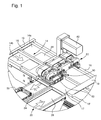
- Fig. 1 and Fig. 2 both show a switch 80, which belongs to a manufacturing unit 20 and is mounted above an endless circulating conveyor belt 14.
- the conveyor belt 14 is guided in known manner at two deflection points in each case via a rotatably mounted deflection roller.
- a motor is provided which is not visible in the figures, and which drives the conveyor belt 14 at a constant speed in a transport direction T.
- a plurality of workpiece carriers 50 are shown, which essentially have the shape of plates with a frame surrounding a rectangular base.
- any other workpiece carriers can be used, and it is also conceivable to transport workpieces without such a carrier directly on the conveyor belt 14.
- the switch 80 must always be adapted to the dimensions of the workpiece carriers used.
- the conveyor belt 14 is operated in two lanes. Each of the two tracks 14a, 14b is just wide enough for a workpiece carrier 50. On the outside of the The conveyor belt 14 are used in the transport direction T extending boundary webs 18, 18 'as a guide for the workpiece carrier 50. The two tracks 14a, 14b are separated by separating webs 16 which extend parallel to the lateral boundary webs 18, 18' and are held by bridges 19. At the side facing the viewer in the figures of the conveyor belt 14, a docking area 17 is provided at the height of the switch 80, in which the boundary web 18 'is cut out. In the area of this docking area 17, the workpiece carriers 50 can be transferred from the conveyor belt 14 to a production unit 20, from which in the Fig. 1 and 2 only a small part is shown.
- a region without a separating web is left free. This region without a separating web is just long enough to allow a workpiece carrier 50 to pass, and lies under the switch 80.
- a switchover of a workpiece carrier 50 from one track 14b, 14a to the other 14a is effected by the switch 80 and the region without a separating web. 14b, as explained below.
- the separating webs 16 and the limiting webs 18, 18 ' can be fastened both to a cover, not shown in the figures, of the conveyor belt 14 and to a production unit 20. Since the dividers 16 do not necessarily have to sit in the middle of the conveyor belt 14, and in principle can be placed at any point, the division of the conveyor belt 14 in two or more tracks is flexible.
- the diverter 80 is in Fig. 3 shown enlarged. It comprises a vertical support 81 to which a motor 82 is attached. This motor 82 serves to drive a deflection roller 85, over which a circulating belt 84 is guided.
- the belt 84 is perpendicular to the Conveyor belt 14 and extends above this over its entire width, that is from one of the lateral boundary webs 18 to the other 18 '.
- the driven deflection roller 85 and the motor 82 lie above the boundary of the production unit 20 facing away from the driven pulley 85 and one above the other, the production unit 20 facing boundary web 18 lying second pulley 85 'are both each on one side to a rear side part 86 and rotatably mounted on the other side to a central portion 89. Between the rear side part 86 and the middle part 89, a cavity extends into the Figures 1-3 but is obscured by the band 84. On the other side of the middle part 89, a further cavity is provided, which is connected via spacers 98 with a front side part 87. Both the two side parts 86, 87 and the middle part 89 each extend from the driven deflection roller 85 to the second deflection roller 85 '.
- the front side part 86 is formed integrally, the rear side part 86 and the middle part 89 are each composed of two halves. Between the two halves, a gap 72 is provided, the width of which can be regulated in order to adjust the belt tension of the circulating belt 84.
- a total of five pairs of strips 90 are fastened at equal intervals on the outside.
- the distance between two adjacent strip pairs 90 is chosen so that a workpiece carrier 50 just fits between the two strip pairs 90, without jamming.
- the belt 84 is driven by the motor 82 via the guide roller 85, the strip pairs 90 move in a path along the belt 84 about an axis extending parallel to the transporting direction T of the conveyor belt above the separating webs 16.
- Fig. 1 and 3 and 2 respectively different positions are shown in which, however, always three pairs of strips 90 at a bottom of the Soft 80 and two strip pairs 90 are located on an upper side of the switch 80.
- Each pair of ledges 90 includes a fixed ledge 94 secured to the band 84 and an adjustable ledge 92 which is connected to the stationary ledge 94 via connecting pins 93 provided on one side of the ledge pair 90.
- the pins 93 at the same time limit the distance between the two strips 92, 94.
- the pins 93 are each firmly pressed into a hole in the adjustable bar 92 and extend through a further hole in the fixed bar.
- the fixed bar 94 has a region of greater thickness, so that the bore is sufficiently long to form a guide for the pin 93.
- the connecting pin 93 terminates at its beyond the bore in the fixed bar 94 also projecting end with a disc-shaped head 97, whose diameter corresponds approximately to the width of the strips 92, 94, and thus exceeds the diameter of the bore and the connecting pin 93 significantly.
- This disc-shaped head limits the distance between the two strips 92, 94th
- the two front of the in the Fig. 1 to 3 below the switch 80 lying strip pairs 90 are each in an active position in which the fixed bar 92 and the movable bar 94 are spaced from each other. In this position, the head 97 of the connecting pin 93 rests on top of the fixed bar 92 and thereby limits the distance between the two bars 92, 94.
- a total of six sensors 96 are arranged in pairs one above the other.
- the Outlet members 90 are each a pair of sensors 96 at the level of lying on the underside of the switch 80 Ausschleussiatas 90. More specifically, the heads 97 of the Verbindu nsbuilde 93 respectively in front of a pair of sensors 96, wherein a lower sensor 96 is at the same height as the head 97 of the connecting pin 93 when the movable bar 92 is maximally spaced from the fixed bar 94.
- the upper sensor 96 is then at the level of the head 97 of the connecting pin 93, when the adjustable bar 92 abuts against the fixed bar 94, and the discharge element 90 is thus in its neutral position. For a pair of strips 90, therefore, whenever one of the pairs of sensors 96 passes, it can be determined whether the two strips 92, 94 are spaced from each other or abut each other, ie, whether the reject element is in its active or in its neutral position.
- the sensors 96 are connected to a control, not shown in the figures and after issuing a command for adjusting one of the adjustable strips 92 can be checked by means of the sensors 96, whether the desired position has actually been brought about. If this is not the case, for example, an error message can be output.
- the production unit 20 has two parallel, endlessly circulating conveyor belts 24, 26, which are driven in opposite conveying directions F 1 , F 2 .
- the two conveyor belts 24, 26 perpendicular to the conveyor belt 14.
- the in the Fig. 1 and 2 left conveyor belt 24 is used to convey a workpiece carrier 50 of the conveyor belt 14 to a functional element 22 of the manufacturing unit 20, not shown Fig. 1 and 2
- the conveyor belt 26 on the right conveys the workpiece carriers 50 back to the conveyor belt 14.
- Each of the workpiece carriers 50 is provided with an RFID transponder having a writable memory.
- the sequence of the steps to be carried out that is to say the sequence of the production units 20 to be controlled and / or manual workstations, is initially stored in this memory.
- each manufacturing unit 20 may be assigned an identification number, these identification numbers then being stored in the desired order.
- the read heads are mounted on the production unit 20 such that they are mounted in the assembled production unit 20 below the in Fig. 1 and 2 with the reference numeral 44 designated areas of the conveyor belt 14 come to rest.
- An RFID transponder attached to a workpiece carrier 50 can thus be read out when the workpiece carrier 50 on one of the two tracks 14a, 14b of the conveyor belt 14 passes the reading head underneath.
- the read heads are still in front of the switch 80 in relation to the transport direction T of the conveyor belt 14, so that the latter can be actuated in dependence on the data read out by means of the read heads.
- the writing unit on the other hand, which is not shown in the figures, lies under the second conveyor belt 26 and serves to mark or delete the processing step performed by the functional element as done. It can also lie under the first conveyor belt 24, so that the corresponding processing step is already marked as completed before the actual processing.
- the read head transmits the stored information to the control unit of the production unit 20.
- the control unit of the production unit 20 stores the identification number assigned to the respective production unit 20.
- the control unit may check whether the next processing step to be performed stored in the memory of the RFID transponder is the one performed by the present manufacturing unit 20, for example by a simple comparison of the identification numbers. In the event of a match, the controller will issue the command to move the relevant workpiece carrier 50 on the conveyor belt 24 of the manufacturing unit 20.
- a first discharge element 90 is first adjusted to its active state, and then the circulating belt 84 driven by the discharge elements 90.
- the workpiece carrier 50 is thereby pushed by the discharge element 90 on the "turning lane" 14b.
- the same discharge element 90 is left in its active position and the belt 84 is further driven so that the workpiece carrier 50 is pushed onto the conveyor belt 24. From the conveyor belt 24 of the workpiece carrier 50 is then transported to the functional element, not shown, of which the corresponding processing step is performed.
- the second conveyor belt 26 conveys the workpiece carrier 50 again after completion of the processing step in the direction of the conveyor belt 14.
- a slide not shown in the figures or a switch, also not shown in the figures, may be used.
- a writing unit arranged below the second conveyor belt 26 in the writable memory of the workpiece carrier marks the processing step carried out as completed.
- control for the switch 80 can be integrated into the switch 80 itself as well as elsewhere in the manufacturing unit 20. Central control of the entire production line is not required in any case.
Abstract
Description
Die vorliegende Erfindung betrifft eine Weiche, welche dazu bestimmt ist, oberhalb eines Förderers, beispielsweise eines Förderbandes einer Fertigungslinie, angebracht zu werden, und dazu dient, Werkstückträger, die auf dem Förderer in eine Förderrichtung transportiert werden, wahlweise in eine andere Richtung umzulenken oder ohne Richtungsänderung durchzulassen.The present invention relates to a switch, which is intended to be mounted above a conveyor, for example a conveyor belt of a production line, and serves to deflect workpiece carriers, which are transported on the conveyor in a conveying direction, either in another direction or without Pass direction change.
Derartige Weichen kommen insbesondere in Fertigungslinien zum Einsatz, bei denen ein zu bearbeitendes Werkstück auf einem Transportband von einer Bearbeitungsstation zur nächsten transportiert wird, und an jeder Bearbeitungsstation ein Fertigungsschritt durchgeführt wird. Mit Hilfe einer Weiche der eingangs genannten Art kann das Werkstück, bzw. ein Werkstückträger mit einem darauf liegenden Werkstück, von dem Transportband zu einer Bearbeitungsstation ausgeschleust werden. Insbesondere bei modularen Fertigungslinien müssen diese Weichen elektronisch ansteuerbar sein, um einen Werkstückträger je nach Bedarf in Richtung einer Fertigungsstation auszuschleusen oder auf dem Transportband weiter zu transportieren. Bisher werden zum Ausschleusen von einzelnen Werkstückträgern häufig einfache Schieber verwendet. Bei komplizierten Anordnungen, vor allem, wenn ein mehrspurig betriebenes Transportband verwendet wird, ist dies jedoch nicht zufrieden stellend, da sowohl für Spurwechsel als auch zum Ausschleusen und zur Rückgabe eines Werkstückträgers von einer Fertigungseinheit an das Transportband jeweils separate Schieber benötigt werden. Die Ansteuerung einer Vielzahl separater Schieber ist jedoch vergleichsweise kompliziert. Jeder Schieber muss, nachdem er einen Werkstückträger verschoben hat, wieder an seine Ausgangsposition zurückgefahren werden, und ist somit nicht sofort wieder einsatzbereit. Um dennoch eine hohe Fertigungsrate zu erzielen, müssen die Schieber mit hohen Geschwindigkeiten bewegt werden. Um zu vermeiden, dass mehrere Schieber sich gegenseitig behindern, werden diese bei herkömmlichen Fertigungslinien nebeneinander angeordnet, so dass für eine Ausschleusungs- und Spurwechsel- Weiche, die mit Schiebern realisiert wird, viel Platz benötigt wird.Such switches are used in particular in production lines, in which a workpiece to be machined is transported on a conveyor belt from one processing station to the next, and at each processing station, a manufacturing step is performed. With the help of a switch of the type mentioned, the workpiece, or a workpiece carrier with a workpiece lying thereon, are discharged from the conveyor belt to a processing station. In particular, in modular production lines, these switches must be electronically controlled to eject a workpiece carrier as needed in the direction of a manufacturing station or to transport on the conveyor belt on. So far, simple slides are often used for discharging individual workpiece carriers. In complicated arrangements, especially when a multi-track operated conveyor belt is used, but this is not satisfactory, since both for lane change and for discharging and return of a workpiece carrier from a manufacturing unit to the conveyor belt each separate slides are needed. The control of a variety of separate slide is, however comparatively complicated. Each slide must be moved back to its original position after it has moved a workpiece carrier and is therefore not immediately ready for use. Nevertheless, to achieve a high production rate, the slide must be moved at high speeds. In order to avoid that several slides interfere with each other, these are arranged side by side in conventional production lines, so that for a Ausschleusungs- and lane change switch, which is realized with sliders, a lot of space is needed.
Der vorliegenden Erfindung liegt daher die Aufgabe zugrunde, eine Weiche zu schaffen, die die geschilderten Nachteile überwindet, und auch in komplexen Fertigungslinien mit zufrieden stellenden Ergebnissen eingesetzt werden kann.The present invention is therefore an object of the invention to provide a switch, which overcomes the disadvantages described, and can be used in complex production lines with satisfactory results.
Diese Aufgabe wird erfindungsgemäss durch eine Weiche gemäss Anspruch 1 gelöst.This object is achieved according to the invention by a switch according to claim 1.
Die erfindungsgemässe Weiche ist dazu bestimmt, oberhalb eines Förderers angebracht zu werden, auf welchem Werkstückträger in eine Förderrichtung transportiert werden. Bei dem Förderer kann es sich beispielsweise um ein ein- oder mehrspurig betriebenes Transportband handeln. Die Weiche umfasst wenigstens ein Ausschleuselement, welches entlang einer geschlossenen Bahn beweglich ist, wobei diese geschlossene Bahn symmetrisch um eine Achse verläuft, die sich parallel zu der Förderrichtung erstreckt. Zudem ist das Ausschleuselement zwischen einer neutralen Position und einer in Bezug auf die Achse der Bahn aussenseitig von der neutralen Position liegenden aktiven Position verstellbar. Wenn das Ausschleuselement sich in seiner neutralen Position befindet, kann ein Werkstückträger, der unter der Weiche auf dem Förderer transportiert wird, unabhängig von der Bewegung des Ausschleuselementes auf der Bahn ungehindert seinen Weg fortsetzen. Wenn das Ausschleuselement sich jedoch in seiner aktiven Position aussenseitig von der neutralen Position befindet, dann existiert ein Abschnitt der Bahn, auf dem es näher an dem Förderer liegt. Bei geschickter Wahl der Geometrie der Bahn und des Abstandes des Ausschleuselementes von dem Förderer verschiebt das Ausschleuselement einen auf dem Förderer liegenden Werkstückträger in Richtung seiner Bewegung entlang der Bahn.The inventive switch is intended to be mounted above a conveyor on which workpiece carriers are transported in a conveying direction. The conveyor may be, for example, a single or multi-track operated conveyor belt. The switch comprises at least one discharge element which is movable along a closed path, said closed path being symmetrical about an axis extending parallel to the conveying direction. In addition, the outfeed element is adjustable between a neutral position and an active position outside the neutral position with respect to the axis of the web. When the rejection member is in its neutral position, a workpiece carrier carried under the diverter on the conveyor can continue unimpeded independently of the movement of the diverter element on the conveyor. However, when the ejection element is in its active position on the outside of the neutral position, then there is a portion of the track on which it is closer to the conveyor. With skillful choice of the geometry of the web and the distance of the discharge element from the conveyor, the discharge element displaces a workpiece carrier lying on the conveyor in the direction of its movement along the path.
Gemäss einer besonders bevorzugten Ausführungsform der Erfindung sind mehrere Ausschleuselemente vorgesehen, die jeweils unabhängig voneinander verstellbar sind. Dadurch kann die Effizienz der Weiche erhöht werden.According to a particularly preferred embodiment of the invention, a plurality of discharge elements are provided which are each independently adjustable. This can increase the efficiency of the switch.
Vorzugsweise sind die Ausschleuselemente derart miteinander gekoppelt, dass sie nur gemeinsam entlang der Bahn beweglich sind. Beispielsweise können mehrere Ausschleuselemente an einem entlang der geschlossenen Bahn umlaufenden, mit einem Antrieb verbundenen Band befestigt sein, wobei ein Antreiben des Bandes eine Bewegung der Ausschleuselemente entlang der Bahn bewirkt. Vorzugsweise kann der Antrieb sowohl vorwärts als auch rückwärts angetrieben werden. Ein solcher Antrieb kann sowohl Bestandteil der Weiche sein, als auch an anderer Stelle bereitgestellt werden.Preferably, the discharge elements are coupled together so that they are only movable together along the path. For example, a plurality of discharge elements may be attached to a belt connected to a drive along the closed path, wherein driving of the belt causes movement of the discharge elements along the path. Preferably, the drive can be driven both forward and backward. Such a drive can be both part of the switch, as well as provided elsewhere.
Wenn ein Band verwendet wird, an dem mehrere Ausschleuselemente mit gleichmässigen Abständen voneinander befestigt sind, dann sollte der Abstand dabei geringfügig grösser als die Breite der zu befördernden Werkstücke oder Werkstückträger gewählt werden, so dass direkt nacheinander auf dem Transportband beförderte Werkstücke oder Werkstückträger von zwei benachbarten Ausschleuselementen in einer Bewegung nacheinander ausgeschleust werden können.If a belt is used, to which a plurality of discharge elements are fixed at regular intervals from each other, then the distance should be slightly larger than the width of the workpieces or workpiece carriers to be transported, so that directly successively conveyed on the conveyor belt workpieces or workpiece carriers of two adjacent Outward transfer elements can be discharged in one movement in succession.
Gemäss einer bevorzugten Ausführungsform der Erfindung ist das Ausschleuselement bzw. sind die Ausschleuselemente entlang der Bahn in zwei einander entgegen gesetzte Richtungen beweglich. Damit kann ein- und dasselbe Ausschleuselement je nach Bewegungsrichtung sowohl ein Werkstück von einem Transportband weg ausschleusen, als auch umgekehrt von einer Fertigungseinheit zurück auf ein Transportband verschieben.According to a preferred embodiment of the invention, the discharge element or the discharge elements are movable along the path in two mutually opposite directions. Thus, one and the same discharge element depending on the direction of movement both a Move workpiece away from a conveyor belt, as well as move vice versa from a manufacturing unit back to a conveyor belt.
Gemäss einer besonders vorteilhaften Ausführungsform der Erfindung weist die Weiche auch eine mit einer Steuerung gekoppelte Betätigungseinheit zum Verstellen der Ausschleuselemente von der neutralen Position in die aktive Position auf.
Die Betätigungseinheit kann beispielsweise einen Magneten oder ein pneumatisches Element umfassen.According to a particularly advantageous embodiment of the invention, the switch also has a control unit coupled to an actuating unit for adjusting the discharge elements from the neutral position to the active position.
The actuating unit may comprise, for example, a magnet or a pneumatic element.
Vorzugsweise verfügt die erfindungsgemässe Weiche über einen mit einer Steuerung gekoppelten Sensor, welcher feststellt, ob das Ausschleuselement sich in der neutralen oder in der aktiven Position befindet. Mit Hilfe des Sensors kann festgestellt werden, ob ein von einer Steuerung an ein Betätigungselement gegebener Befehl auch erfolgreich ausgeführt worden ist. Falls dem nicht so sein sollte, beispielsweise aufgrund eines Defekts, so wird dies dank des Sensors sofort bemerkt. In einem solchen Fall kann eine Steuerung der Weiche dann veranlassen, dass eine Fehlermeldung ausgegeben wird, oder kann sogar an eine Zentraleinheit einen Befehl zum Anhalten der Fertigungslinie senden, um Folgeschäden zu vermeiden.Preferably, the switch according to the invention has a sensor coupled to a controller, which determines whether the discharge element is in the neutral or in the active position. With the aid of the sensor it can be determined whether an instruction given by a controller to an actuating element has also been successfully executed. If this is not the case, for example due to a defect, this is immediately noticed thanks to the sensor. In such a case, control of the switch may then cause an error message to be issued or may even send a command to stop a production line to a central processing unit to avoid consequential damage.
Das Ausschleuselement ist gemäss einer aufgrund ihrer Einfachheit bevorzugten Ausführungsform als horizontales, sich parallel zu der Achse der Bahn erstreckendes Leistenpaar ausgebildet, wobei die beiden Leisten des Paares in der neutralen Position aneinander anliegen und in der aktiven Position voneinander beabstandet sind. Wenn die Ausschleuselemente von einem Band auf der geschlossenen Bahn geführt werden, dann kann jeweils eine erste Leiste an dem Band befestigt sein, während die zweite Leiste des Paares beweglich an der ersten Leiste befestigt ist.The discharge element is formed according to a preferred embodiment for its simplicity as a horizontal, parallel to the axis of the web extending pair of strips, the two strips of the pair in the neutral position abut each other and are spaced apart in the active position. If the discharge elements are guided by a band on the closed path, then a first strip can be attached to the band, while the second strip of the pair is movably attached to the first strip.
Die erfindungsgemässe Weiche kann beispielsweise in einer Fertigungslinie mit einem Transportband und mehreren Fertigungseinheiten verwendet werden, bei der jede Fertigungseinheit ein Funktionselement und Förderbänder oder andere Mittel zum Befördern von Werkstückträgern von dem Transportband zu dem Funktionselement und umgekehrt umfasst.The switch according to the invention can be used for example in a production line with a conveyor belt and several production units, in which each production unit comprises a functional element and conveyor belts or other means for conveying workpiece carriers from the conveyor belt to the functional element and vice versa.
Mit Hilfe eines Ausschleuselementes kann ein Werkstückträger von dem Transportband auf ein Förderband geschoben werden, auf dem er dann zu dem Funktionselement befördert wird. Nach erfolgter Bearbeitung durch das Funktionselement kann der Werkstückträger von dem zweiten Förderband zurück in Richtung des Transportbandes befördert werden, um anschliessend von einem sich nun in die Gegenrichtung Richtung bewegenden Ausschleuselement der Weiche wieder auf das Transportband geschoben zu werden. Die Werkstückträger werden dabei vorzugsweise nicht gestoppt, sondern die Weiche wird so gesteuert, dass diese aus der Bewegung auf dem Transportband heraus in Richtung des Funktionselementes der Fertigungseinheit umgelenkt werden. Dadurch werden die bei einem abrupten Stoppen der Werkstückträger auftretenden hohen Beschleunigungen vermieden, und der Ausschleusungsvorgang von dem Transportband zu der Fertigungseinheit nimmt nur sehr wenig Zeit in Anspruch. Die Weiche kann dabei schon "anfahren", bevor der Werkstückträger vollständig unter der Weiche liegt, so dass er gleichzeitig weiter in die Transportrichtung befördert und von der Weiche umgelenkt wird. In diesem Fall ergibt sich dann eine kurvenförmige Bahn des Werkstückträgers von dem Transportband in Richtung der Fertigungseinheit.With the aid of an ejection element, a workpiece carrier can be pushed by the conveyor belt onto a conveyor belt, on which it is then conveyed to the functional element. After processing by the functional element, the workpiece carrier can be conveyed by the second conveyor belt back in the direction of the conveyor belt to be subsequently pushed back onto the conveyor belt by a diverting element of the diverter now moving in the opposite direction. The workpiece carriers are preferably not stopped, but the switch is controlled so that they are deflected from the movement on the conveyor belt out in the direction of the functional element of the manufacturing unit. As a result, the high accelerations occurring when the workpiece carriers abruptly stop are avoided, and the discharge process from the conveyor belt to the production unit takes only a very short time. The switch may already "approach" before the workpiece carrier is completely under the switch, so that it simultaneously transported further in the transport direction and is deflected by the switch. In this case, then results in a curved path of the workpiece carrier of the conveyor belt in the direction of the production unit.
Um ruckartige Bewegungen und hohe Beschleunigungen der Werkstückträger und damit der darauf befindlichen Werkstücke zu vermeiden, kann die Weiche so angesteuert werden, dass sich eine in etwa sinusförmige Geschwindigkeitskurve der Ausschleuselemente ergibt. Der Werkstückträger wird also nach und nach bis auf eine Maximalgeschwindigkeit beschleunigt, und vor der Übergabe an ein Förderband bzw. das Transportband wieder abgebremst. Auf diese Weise wird die Zeit, die zum Verschieben des Werkstückträgers benötigt wird, minimiert, ohne dass das auf dem Werkstückträger befindliche Werkstück den bei den hohen Beschleunigungen und ruckartigen Bewegungen auftretenden Kräften ausgesetzt würde.To avoid jerky movements and high accelerations of the workpiece carrier and thus of the workpieces located thereon, the switch can be controlled so that there is an approximately sinusoidal velocity curve of the discharge elements. The workpiece carrier is thus gradually accelerated to a maximum speed, and before the transfer to a Brake conveyor or the conveyor belt braked again. In this way, the time required to move the workpiece carrier is minimized without exposing the workpiece located on the workpiece carrier to the forces encountered in the high accelerations and jerky movements.
Bei einem zwei- oder mehrspurig betriebenen Transportband kann die erfindungsgemässe Weiche auch dazu verwendet werden, die Werkstückträger von einer Spur auf die andere zu verschieben. Wenn die Fertigungseinheiten alle auf einer Seite des Transportbandes angeordnet sind, fungiert eine der beiden Spuren gewissermassen als Abbiegespur, während die den Fertigungseinheiten abgewandte Spur als Überholspur dient.In a two- or multi-track operated conveyor belt, the inventive switch can also be used to move the workpiece carrier from one track to the other. If the production units are all arranged on one side of the conveyor belt, one of the two tracks effectively acts as a turning lane, while the lane facing away from the production units serves as a passing lane.
Eines der Ausschleuselemente kann beispielsweise einen auf der von der Fertigungseinheit abgewandten Spur ("Überholspur") des Transportbandes liegenden Werkstückträger auf die der Fertigungseinheit zugewandte Spur ("Abbiegespur") des Transportbandes verschieben. Anschliessend kann dieser Werkstückträger dann von dem gleichen Ausschleuselement auf ein Förderband geschoben werden, welches ihn zu dem Funktionselement bringt. Alternativ kann der von der Überholspur auf die Abbiegespur verschobene Werkstückträger auch auf der Abbiegespur weiter transportiert werden. Hierfür muss das Ausschleuselement nach dem Verschieben des Werkstückträgers auf die Abbiegespur in seine neutrale Position verstellt werden. Das Transportband kann je nach Art der konkreten Anwendung auch mit mehr als zwei Spuren betrieben werden.One of the discharge elements can, for example, move a workpiece carrier lying on the track ("passing lane") of the conveyor belt away from the production unit to the track ("turning lane") of the conveyor belt facing the production unit. Subsequently, this workpiece carrier can then be pushed by the same discharge element on a conveyor belt, which brings him to the functional element. Alternatively, the workpiece carrier shifted from the fast lane to the lane track can also be transported on the lane track. For this purpose, the ejection element must be adjusted to its neutral position after moving the workpiece carrier on the turning lane. Depending on the type of concrete application, the conveyor belt can also be operated with more than two tracks.
Wenn das umlaufende Band der Weiche in die andere Richtung angetrieben wird, kann ein Werkstückträger, der nicht zu der nächsten Fertigungseinheit hin ausgeschleust werden soll, von der der Fertigungseinheit zugewandten Spur ("Abbiegespur") des Transportbandes auf die der Fertigungseinheit abgewandte Spur ("Überholspur") verschoben werden. Es können auch zwei nebeneinander angeordnete Weichen verwendet werden, die in einander entgegen gesetzte Richtungen angetrieben sind. Der Antrieb kann dabei mit einem Motor realisiert werdne, der beiden Weichen gemeinsam ist.If the circulating belt of the switch is driven in the other direction, a workpiece carrier, which is not to be discharged to the next production unit, from the production unit facing track ("turning lane") of the conveyor belt on the production unit facing away lane ("Fast lane ") are moved. It can also have two side by side switches used, which are driven in opposite directions. The drive can be realized with a motor werdne, which is common to both switches.
Im Folgenden soll die Erfindung anhand eines bevorzugten Ausführungsbeispiels und unter Bezugnahme auf die beigefügten Zeichnungen näher beschrieben werden.In the following, the invention will be described with reference to a preferred embodiment and with reference to the accompanying drawings.
Dabei zeigen die Zeichnungen im Einzelnen:
-
Fig. 1 : eine perspektivische Ansicht einer an einer Fertigungslinie montierten Weiche, -
Fig. 2 : die Weiche ausFig. 1 in einer anderen Position, -
Fig. 3 : einen vergrösserten Ausschnitt ausFig. 1 .
-
Fig. 1 FIG. 3: a perspective view of a switch mounted on a production line, FIG. -
Fig. 2 : the switch offFig. 1 in another position, -
Fig. 3 : an enlarged sectionFig. 1 ,
In den Figuren sind beispielhaft jeweils mehrere Werkstückträger 50 dargestellt, die im Wesentlichen die Form von Tellern mit einem eine rechteckige Grundfläche umgebenden Rahmen besitzen. Selbstverständlich können auch beliebige andere Werkstückträger verwendet werden, und es ist auch denkbar, zu bearbeitende Werkstücke ohne einen solchen Träger direkt auf dem Transportband 14 zu transportieren. Die Weiche 80 muss in jedem Fall an die Dimensionen der verwendeten Werkstückträger angepasst sein.In the figures, for example, in each case a plurality of
Wie man in den
Auch zwischen den Trennstegen 16, welche die beiden Spuren 14a, 14b voneinander trennen, ist ein Bereich ohne einen Trennsteg frei gelassen. Dieser Bereich ohne Trennsteg ist gerade lang genug, um einen Werkstückträger 50 passieren zu lassen, und liegt unter der Weiche 80. Durch die Weiche 80 und den Bereich ohne Trennsteg wird ein Spurwechsel eines Werkstückträgers 50 von einer Spur 14b, 14a auf die andere 14a, 14b ermöglicht, wie weiter unten erläutert wird.Also between the separating
Die Trennstege 16 und die Begrenzungsstege 18, 18' können sowohl an einer in den Figuren nicht gezeigten Abdeckung des Transportbandes 14 als auch an einer Fertigungseinheit 20 befestigt sein. Da die Trennstege 16 nicht zwangsläufig in der Mitte des Transportbandes 14 sitzen müssen, und im Prinzip an beliebiger Stelle platziert werden können, ist die Einteilung des Transportbandes 14 in zwei oder mehr Spuren flexibel.The separating
Die Weiche 80 ist in
An dem umlaufenden Band 84 sind aussenseitig insgesamt fünf Leistenpaare 90 in gleichmässigen Abständen befestigt. Der Abstand zwischen zwei benachbarten Leistenpaaren 90 ist dabei so gewählt, dass ein Werkstückträger 50 gerade zwischen die beiden Leistenpaare 90 passt, ohne zu verklemmen. Wenn das Band 84 über die Umlenkrolle 85 von dem Motor 82 angetrieben wird, bewegen sich die Leistenpaare 90 auf einer Bahn entlang des Bandes 84 um eine sich parallel zu der Transportrichtung T des Transportbandes oberhalb der Trennstege 16 erstreckende Achse. In den
Jedes Leistenpaar 90 umfasst eine feststehende Leiste 94, die an dem Band 84 befestigt ist, und eine verstellbare Leiste, 92, die über an einer Seite aussen an dem Leistenpaar 90 vorgesehene Verbindungsstifte 93 mit der feststehenden Leiste 94 verbunden ist. Die Verbindungsstifte 93 begrenzen dabei gleichzeitig den Abstand zwischen den beiden Leisten 92, 94. Die Stifte 93 sind jeweils in einer Bohrung in der verstellbaren Leiste 92 fest eingepresst und erstrecken sich durch eine weitere Bohrung in der feststehenden Leiste hindurch. Im Bereich dieser Bohrung weist die feststehende Leiste 94 einen Bereich grösserer Dicke auf, so dass die Bohrung ausreichend lang ist, um eine Führung für den Stift 93 zu bilden. Durch diese Führung des Stifts 93 in der Bohrung wird die verstellbare Leiste 92 parallel zu der feststehenden Leiste und damit parallel zu dem Transportband 14 gehalten. Der Verbindungsstift 93 endet an seinem über die Bohrung in der feststehenden Leiste 94 hinaus ragenden Ende mit einem scheibenförmigen Kopf 97, dessen Durchmesser in etwa der Breite der Leisten 92, 94 entspricht, und damit den Durchmesser der Bohrung und des Verbindungsstiftes 93 deutlich überschreitet. Dieser scheibenförmige Kopf begrenzt den Abstand zwischen den beiden Leisten 92, 94.Each pair of
Die beiden vorderen der in den
An der Aussenseite des vorderen Seitenteils 87 sind insgesamt sechs Sensoren 96 jeweils paarweise übereinander angeordnet. In der in
Die Ansteuerung der verstellbaren Leisten 92 erfolgt über zwischen dem Mittelteil 89 und dem vorderen Seitenteil 87 angeordnete Pneumatikzylinder 88.The actuation of the
Wie man in
Die bereits erwähnte, in den
Die Fertigungseinheit 20 weist zwei parallel verlaufende, endlos umlaufende Förderbänder 24, 26 auf, die in einander entgegen gesetzte Förderrichtungen F1, F2 angetrieben sind. Wenn die Fertigungseinheit 20 auf im Grundgestell 10 befestigt ist, verlaufen die beiden Förderbänder 24, 26 senkrecht zu dem Transportband 14. Das in den
In die Fertigungseinheit 20 sind zudem zwei in den Figuren nicht dargestellte RFID - Leseköpfe und eine in den Figuren ebenfalls nicht dargstellte Schreibeinheit zum Beschreiben eines in einen RFID - Transponder integrierten Speichers integriert.In addition, two RFID read heads (not shown in the figures) and a write unit likewise not illustrated in the figures for writing a memory integrated in an RFID transponder are integrated into the
Jeder der Werkstückträger 50 ist mit einem RFID - Transponder versehen, der einen beschreibbaren Speicher besitzt. In diesem Speicher wird zu Beginn die Reihenfolge der durchzuführenden Schritte, das heisst die Reihenfolge der anzusteuernden Fertigungseinheiten 20 und/oder Handarbeitsplätze abgespeichert. Beispielsweise kann jeder Fertigungseinheit 20 eine Kennnummer zugeordnet werden, wobei diese Kennnummern dann in der gewünschten Reihenfolge gespeichert werden.Each of the
Die Leseköpfe sind derart an der Fertigungseinheit 20 angebracht, dass sie bei montierter Fertigungseinheit 20 unterhalb der in
Wenn ein Werkstückträger 50 von dem Transportband 14 über einen der beiden Leseköpfe transportiert wird, gibt der Lesekopf die gespeicherten Informationen an die Steuereinheit der Fertigungseinheit 20 weiter. In der Steuereinheit der Fertigungseinheit 20 ist die der jeweiligen Fertigungseinheit 20 zugeordnete Kennnummer gespeichert. Die Steuereinheit kann also nach Erhalt der Daten von dem Lesekopf prüfen, ob der in dem Speicher des RFID-Transponders gespeicherte nächste durchzuführende Bearbeitungsschritt derjenige ist, der von der vorliegenden Fertigungseinheit 20 durchgeführt wird, beispielsweise durch einen einfachen Vergleich der Kennnummern. Im Fall einer Übereinstimmung wird die Steuerung den Befehl erteilen, den betreffenden Werkstückträger 50 auf das Förderband 24 der Fertigungseinheit 20 zu verschieben. Hierzu wird zunächst, falls der Werkstückträger 50 sich auf der dem Förderband 24 abgewandten Spur 14a befindet, ein erstes Ausschleuselement 90 ins seinen aktiven Zustand verstellt, und dann das umlaufende Band 84 mit den Ausschleuselementen 90 angetrieben. Der Werkstückträger 50 wird dadurch von dem Ausschleuselement 90 auf die "Abbiegespur" 14b geschoben. Im Anschluss wird das gleiche Ausschleuselement 90 in seiner aktiven Position belassen und das Band 84 weiter angetrieben, sodass der Werkstückträger 50 auf das Förderband 24 geschoben wird. Von dem Förderband 24 wird der Werkstückträger 50 anschliessend zu dem nicht dargestellten Funktionselement befördert, von dem der entsprechende Bearbeitungsschritt ausgeführt wird.When a
Das zweite Förderband 26 befördert den Werkstückträger 50 nach Abschluss des Bearbeitungsschrittes wieder in Richtung des Transportbandes 14. Um den Werkstücksträger 50 dann von diesem zweiten Förderband 26 auf die in "Überholspur" 14b des Transportbandes 14 zu befördern, kann ein in den Figuren nicht dargestellter Schieber oder eine in den Figuren ebenfalls nicht dargestellte Weiche verwendet werden. Vor der Übergabe an das Transportband 14 markiert eine unterhalb des zweiten Förderbandes 26 angeordnete Schreibeinheit in dem beschreibbaren Speicher des Werkstückträgers den durchgeführten Bearbeitungsschritt als erledigt.The
Die bereits erwähnte Steuerung für die Weiche 80 kann im Übrigen sowohl in die Weiche 80 selbst als auch an anderer Stelle in die Fertigungseinheit 20 integriert sein. Eine zentrale Steuerung der gesamten Fertigungslinie ist in keinem Fall erforderlich.Incidentally, the already mentioned control for the
- 1414
- Transportbandconveyor belt
- 14a, 14b14a, 14b
- Spur auf TransportbandTrack on conveyor belt
- 15, 15'15, 15 '
- Umlenkpunktturning point
- 1616
- Trennstegdivider
- 1717
- Andockbereichdocking
- 18, 18'18, 18 '
- Begrenzungssteglimiting web
- 1919
- Brückebridge
- 2020
- Fertigungseinheitmanufacturing unit
- 24, 2624, 26
- Förderbandconveyor belt
- 4444
- Ort, unter dem Lesekopf angeordnet istLocation, located under the reading head
- 50, 50'50, 50 '
- WerkstückträgerWorkpiece carrier
- 7272
- Spaltgap
- 8080
- Weicheswitch
- 8181
- Träger für MotorCarrier for engine
- 8282
- Motorengine
- 8484
- umlaufendes Bandcirculating band
- 85, 85'85, 85 '
- Umlenkrolleidler pulley
- 8686
- rückwärtiges Seitenteilrear side panel
- 8787
- vorderes Seitenteilfront side panel
- 8888
- Pneumatikzylinderpneumatic cylinder
- 8989
- Mittelteilmidsection
- 9090
- Ausschleuselementejecting element
- 9292
- verstellbare Leisteadjustable bar
- 9393
- Verbindungsstiftconnecting pin
- 9494
- feste Leistesolid bar
- 9595
- Mitnehmertakeaway
- 9696
- Sensorsensor
- 9797
- Kopf des VerbindungsstiftesHead of the connecting pin
- 9898
- Abstandshalterspacer
- F1 F 1
- Förderrichtungconveying direction
- F2 F 2
- Förderrichtungconveying direction
- TT
- Transportrichtungtransport direction
- R, VR, V
- Bewegungsrichtung des BandesDirection of movement of the band
Claims (12)
dadurch gekennzeichnet, dass mehrere Ausschleuselemente 90 vorgesehen sind, die jeweils unabhängig voneinander verstellbar sind.Switch 80 according to claim 1,
characterized in that a plurality of discharge elements 90 are provided which are each independently adjustable.
dadurch gekennzeichnet, dass die Ausschleuselemente 90 derart miteinander gekoppelt sind, dass sie nur gemeinsam entlang der Bahn beweglich sind.Switch 80 according to claim 2,
characterized in that the discharge elements 90 are coupled together such that they are movable only together along the path.
dadurch gekennzeichnet, dass die Bahn zumindest einen Abschnitt aufweist, der horizontal verläuft.Switch 80 according to one of the preceding claims,
characterized in that the web has at least a portion which extends horizontally.
dadurch gekennzeichnet, dass das Ausschleuselement 90 entlang der Bahn in zwei einander entgegen gesetzte Richtungen R, V beweglich ist.Switch 80 according to one of the preceding claims,
characterized in that the discharge element 90 is movable along the path in two mutually opposite directions R, V.
dadurch gekennzeichnet, dass das Ausschleuselement 90 an einem entlang der geschlossenen Bahn umlaufenden, mit einem Antrieb 82 verbundenen Band 84 befestigt ist, wobei ein Antreiben des Bandes 84 eine Bewegung des Ausschleuselementes 90 entlang der Bahn bewirkt.Switch 80 according to one of the preceding claims,
characterized in that the discharge element 90 is secured to a belt 84 circulating along the closed path and connected to a drive 82, wherein driving of the belt 84 causes movement of the discharge element 90 along the path.
dadurch gekennzeichnet, dass mehrere Ausschleuselemente 90 mit gleichmässigen Abständen voneinander an dem Band 84 befestigt sind.Switch 80 according to claim 6,
characterized in that a plurality of discharge elements 90 are fixed at uniform intervals from each other on the belt 84.
dadurch gekennzeichnet, dass sie einen Antrieb 82 zum Antreiben des Bandes 84 aufweist, insbesondere einen sowohl vorwärts als auch rückwärts antreibbaren Antrieb.Switch 80 according to claim 6 or 7,
characterized in that it comprises a drive 82 for driving the belt 84, in particular a drive drivable both forwards and backwards.
dadurch gekennzeichnet, dass sie eine mit einer Steuerung gekoppelte Betätigungseinheit 88 zum Verstellen der Ausschleuselemente 90 von der neutralen Position in die aktive Position umfasst.Switch 80 according to one of the preceding claims,
characterized in that it comprises a control unit coupled to a control unit 88 for adjusting the discharge elements 90 from the neutral position to the active position.
dadurch gekennzeichnet, dass die Betätigungseinheit 88 einen Magneten oder ein pneumatisches Element umfasst.Switch 80 according to one of the preceding claims,
characterized in that the actuating unit 88 comprises a magnet or a pneumatic element.
dadurch gekennzeichnet, dass sie einen mit einer Steuerung gekoppelten Sensor 96 aufweist, welcher feststellt, ob das Ausschleuselement 90 sich in der neutralen oder in der aktiven Position befindet.Switch 80 according to one of the preceding claims,
characterized in that it comprises a sensor 96 coupled to a controller which determines whether the discharge element 90 is in the neutral or in the active position.
dadurch gekennzeichnet, dass das Ausschleuselement 90 als horizontales, sich parallel zu der Achse der Bahn erstreckendes Leistenpaar ausgebildet ist, wobei die beiden Leisten 92, 94 des Paares in der neutralen Position aneinander anliegen und in der aktiven Position voneinander beabstandet sind.Switch according to one of the preceding claims,
characterized in that the ejection element 90 is formed as a horizontal, parallel to the axis of the web extending pair of strips, the two strips 92, 94 of the pair abut each other in the neutral position and are spaced apart in the active position.
Priority Applications (5)
| Application Number | Priority Date | Filing Date | Title |
|---|---|---|---|
| AT07123171T ATE517833T1 (en) | 2007-12-13 | 2007-12-13 | SWITCH FOR SUPPORTERS |
| EP07123171A EP2070847B1 (en) | 2007-12-13 | 2007-12-13 | Diverter for conveyors |
| EP08020774A EP2070648B1 (en) | 2007-12-13 | 2008-11-28 | Transport belt module |
| AT08020774T ATE511942T1 (en) | 2007-12-13 | 2008-11-28 | CONVEYOR BELT MODULE |
| US12/627,158 US20100133069A1 (en) | 2007-12-13 | 2009-11-30 | Conveyor belt module |
Applications Claiming Priority (1)
| Application Number | Priority Date | Filing Date | Title |
|---|---|---|---|
| EP07123171A EP2070847B1 (en) | 2007-12-13 | 2007-12-13 | Diverter for conveyors |
Publications (2)
| Publication Number | Publication Date |
|---|---|
| EP2070847A1 true EP2070847A1 (en) | 2009-06-17 |
| EP2070847B1 EP2070847B1 (en) | 2011-07-27 |
Family
ID=39316585
Family Applications (1)
| Application Number | Title | Priority Date | Filing Date |
|---|---|---|---|
| EP07123171A Active EP2070847B1 (en) | 2007-12-13 | 2007-12-13 | Diverter for conveyors |
Country Status (2)
| Country | Link |
|---|---|
| EP (1) | EP2070847B1 (en) |
| AT (1) | ATE517833T1 (en) |
Cited By (4)
| Publication number | Priority date | Publication date | Assignee | Title |
|---|---|---|---|---|
| DE102009033183A1 (en) * | 2009-07-13 | 2011-01-27 | Ief Werner Gmbh | Transport system for a production plant |
| DE102010017828A1 (en) * | 2010-04-20 | 2011-10-20 | Mtu Aero Engines Gmbh | Method for controlling of processing machine for processing component, involves clamping component in tensioning device of component retainer and measuring component in its actual position |
| WO2012062862A1 (en) * | 2010-11-12 | 2012-05-18 | Christian Hieronimi | System for determining and/or monitoring the orientation of objects |
| DE102020132677A1 (en) | 2020-12-08 | 2022-06-09 | CENTRO Kontrollsysteme Gesellschaft mit beschränkter Haftung | Sorting unit and ejection method |
Citations (3)
| Publication number | Priority date | Publication date | Assignee | Title |
|---|---|---|---|---|
| DE3916424A1 (en) | 1989-05-19 | 1990-11-22 | Centro Kontrollsysteme | Feeder machine for packages such as boxes - consists of horizontal main belt with parallel belt, and double chain with conveyor plates |
| EP0659665A1 (en) * | 1993-12-23 | 1995-06-28 | P.R.B. Packaging Systems S.R.L. | Device for continuously feeding articles from a main conveying line to intermediate outlet ways arranged angularly with respect to the main line |
| EP1468944A1 (en) * | 1998-11-25 | 2004-10-20 | United Parcel Service Of America, Inc. | Overhead mounted sorter for conveyors |
-
2007
- 2007-12-13 EP EP07123171A patent/EP2070847B1/en active Active
- 2007-12-13 AT AT07123171T patent/ATE517833T1/en active
Patent Citations (3)
| Publication number | Priority date | Publication date | Assignee | Title |
|---|---|---|---|---|
| DE3916424A1 (en) | 1989-05-19 | 1990-11-22 | Centro Kontrollsysteme | Feeder machine for packages such as boxes - consists of horizontal main belt with parallel belt, and double chain with conveyor plates |
| EP0659665A1 (en) * | 1993-12-23 | 1995-06-28 | P.R.B. Packaging Systems S.R.L. | Device for continuously feeding articles from a main conveying line to intermediate outlet ways arranged angularly with respect to the main line |
| EP1468944A1 (en) * | 1998-11-25 | 2004-10-20 | United Parcel Service Of America, Inc. | Overhead mounted sorter for conveyors |
Cited By (5)
| Publication number | Priority date | Publication date | Assignee | Title |
|---|---|---|---|---|
| DE102009033183A1 (en) * | 2009-07-13 | 2011-01-27 | Ief Werner Gmbh | Transport system for a production plant |
| DE102010017828A1 (en) * | 2010-04-20 | 2011-10-20 | Mtu Aero Engines Gmbh | Method for controlling of processing machine for processing component, involves clamping component in tensioning device of component retainer and measuring component in its actual position |
| WO2012062862A1 (en) * | 2010-11-12 | 2012-05-18 | Christian Hieronimi | System for determining and/or monitoring the orientation of objects |
| US9322903B2 (en) | 2010-11-12 | 2016-04-26 | Christian Hieronimi | System for determining and/or controlling the location of objects |
| DE102020132677A1 (en) | 2020-12-08 | 2022-06-09 | CENTRO Kontrollsysteme Gesellschaft mit beschränkter Haftung | Sorting unit and ejection method |
Also Published As
| Publication number | Publication date |
|---|---|
| EP2070847B1 (en) | 2011-07-27 |
| ATE517833T1 (en) | 2011-08-15 |
Similar Documents
| Publication | Publication Date | Title |
|---|---|---|
| EP3372538B1 (en) | Transport section, method for adjusting and/or configuring at least one transport line within a transport section and packaging plant | |
| DE10313774B4 (en) | Device for processing a moving material web | |
| EP2110348B1 (en) | Palletising device and method for transferring packets from an intake station to a packet grabber | |
| EP2243606B1 (en) | Assembly for producing boards from wooden lamellae and method for producing such boards | |
| WO2003057602A1 (en) | Positioning system | |
| DE69934375T2 (en) | Plant for producing and packaging roll-shaped objects | |
| EP0883565B1 (en) | Conveyor and gathering system | |
| EP0613823B1 (en) | Device for the simultaneous introduction of an object and an insert into a box-like container | |
| EP2070847B1 (en) | Diverter for conveyors | |
| DE4224010A1 (en) | Handling device for strip or sheet of paper - incorporates cross-beams and longitudinal support for tool-carrying positioner guided across path of incoming material | |
| EP2070647B1 (en) | Modular production line | |
| EP1938977B1 (en) | Device and method for drawing at least one material strip or at least one web strand into a folding unit | |
| DE10009672A1 (en) | Wafer block cutter | |
| DE3627498A1 (en) | DEVICE FOR ALIGNING AND ARRANGING PACKAGES | |
| DE3107438A1 (en) | "DEVICE FOR CENTERING ALIGNMENT OF PANEL-SHAPED WORKPIECES" | |
| DE602005000340T3 (en) | FIFO memory with variable capacity, with an ejection station | |
| EP0520945B1 (en) | Method and device for storing and equalising printed products in shingled formation and for closure of gaps in said formation | |
| DE10059312C2 (en) | Centering device for conveyed goods | |
| EP4032669A1 (en) | Multi-track cutting machine with independently controllable grippers | |
| DE4203683A1 (en) | FEEDING DEVICE OF A ROLLER KNIFE ANGLE SHEAR | |
| DE10047385C2 (en) | Method and device for machining continuously moving workpieces | |
| EP1319480A1 (en) | Method and apparatus for blockwise positioning knife holders of a slitting machine | |
| DE10018568C2 (en) | Method for operating a maneuvering unit of a transport device for portions of food to be cut and maneuvering unit | |
| AT516092A1 (en) | Apparatus and method for transporting tubular bag bodies | |
| DE2653895A1 (en) | CONVEYOR DEVICE FOR CHOOSING TRANSPORT TRAILS |
Legal Events
| Date | Code | Title | Description |
|---|---|---|---|
| PUAI | Public reference made under article 153(3) epc to a published international application that has entered the european phase |
Free format text: ORIGINAL CODE: 0009012 |
|
| AK | Designated contracting states |
Kind code of ref document: A1 Designated state(s): AT BE BG CH CY CZ DE DK EE ES FI FR GB GR HU IE IS IT LI LT LU LV MC MT NL PL PT RO SE SI SK TR |
|
| AX | Request for extension of the european patent |
Extension state: AL BA HR MK RS |
|
| 17P | Request for examination filed |
Effective date: 20091217 |
|
| 17Q | First examination report despatched |
Effective date: 20100111 |
|
| RIN1 | Information on inventor provided before grant (corrected) |
Inventor name: BAER, MANFRED Inventor name: DURAND, FRIEDRICH Inventor name: SENN, JEAN-PHILIPPE |
|
| AKX | Designation fees paid |
Designated state(s): AT BE BG CH CY CZ DE DK EE ES FI FR GB GR HU IE IS IT LI LT LU LV MC MT NL PL PT RO SE SI SK TR |
|
| GRAP | Despatch of communication of intention to grant a patent |
Free format text: ORIGINAL CODE: EPIDOSNIGR1 |
|
| RIN1 | Information on inventor provided before grant (corrected) |
Inventor name: BAER, MANFRED Inventor name: SENN, JEAN-PHILIPPE Inventor name: DURAND, FRIEDRICH |
|
| GRAS | Grant fee paid |
Free format text: ORIGINAL CODE: EPIDOSNIGR3 |
|
| GRAA | (expected) grant |
Free format text: ORIGINAL CODE: 0009210 |
|
| AK | Designated contracting states |
Kind code of ref document: B1 Designated state(s): AT BE BG CH CY CZ DE DK EE ES FI FR GB GR HU IE IS IT LI LT LU LV MC MT NL PL PT RO SE SI SK TR |
|
| REG | Reference to a national code |
Ref country code: GB Ref legal event code: FG4D Free format text: NOT ENGLISH |
|
| REG | Reference to a national code |
Ref country code: CH Ref legal event code: EP |
|
| REG | Reference to a national code |
Ref country code: CH Ref legal event code: NV Representative=s name: ICB INGENIEURS CONSEILS EN BREVETS SA |
|
| REG | Reference to a national code |
Ref country code: DE Ref legal event code: R096 Ref document number: 502007007784 Country of ref document: DE Effective date: 20110915 |
|
| REG | Reference to a national code |
Ref country code: NL Ref legal event code: VDEP Effective date: 20110727 |
|
| PG25 | Lapsed in a contracting state [announced via postgrant information from national office to epo] |
Ref country code: IS Free format text: LAPSE BECAUSE OF FAILURE TO SUBMIT A TRANSLATION OF THE DESCRIPTION OR TO PAY THE FEE WITHIN THE PRESCRIBED TIME-LIMIT Effective date: 20111127 Ref country code: NL Free format text: LAPSE BECAUSE OF FAILURE TO SUBMIT A TRANSLATION OF THE DESCRIPTION OR TO PAY THE FEE WITHIN THE PRESCRIBED TIME-LIMIT Effective date: 20110727 Ref country code: PT Free format text: LAPSE BECAUSE OF FAILURE TO SUBMIT A TRANSLATION OF THE DESCRIPTION OR TO PAY THE FEE WITHIN THE PRESCRIBED TIME-LIMIT Effective date: 20111128 Ref country code: SE Free format text: LAPSE BECAUSE OF FAILURE TO SUBMIT A TRANSLATION OF THE DESCRIPTION OR TO PAY THE FEE WITHIN THE PRESCRIBED TIME-LIMIT Effective date: 20110727 Ref country code: FI Free format text: LAPSE BECAUSE OF FAILURE TO SUBMIT A TRANSLATION OF THE DESCRIPTION OR TO PAY THE FEE WITHIN THE PRESCRIBED TIME-LIMIT Effective date: 20110727 Ref country code: LT Free format text: LAPSE BECAUSE OF FAILURE TO SUBMIT A TRANSLATION OF THE DESCRIPTION OR TO PAY THE FEE WITHIN THE PRESCRIBED TIME-LIMIT Effective date: 20110727 |
|
| PG25 | Lapsed in a contracting state [announced via postgrant information from national office to epo] |
Ref country code: LV Free format text: LAPSE BECAUSE OF FAILURE TO SUBMIT A TRANSLATION OF THE DESCRIPTION OR TO PAY THE FEE WITHIN THE PRESCRIBED TIME-LIMIT Effective date: 20110727 Ref country code: SI Free format text: LAPSE BECAUSE OF FAILURE TO SUBMIT A TRANSLATION OF THE DESCRIPTION OR TO PAY THE FEE WITHIN THE PRESCRIBED TIME-LIMIT Effective date: 20110727 Ref country code: GR Free format text: LAPSE BECAUSE OF FAILURE TO SUBMIT A TRANSLATION OF THE DESCRIPTION OR TO PAY THE FEE WITHIN THE PRESCRIBED TIME-LIMIT Effective date: 20111028 Ref country code: CY Free format text: LAPSE BECAUSE OF FAILURE TO SUBMIT A TRANSLATION OF THE DESCRIPTION OR TO PAY THE FEE WITHIN THE PRESCRIBED TIME-LIMIT Effective date: 20110727 Ref country code: PL Free format text: LAPSE BECAUSE OF FAILURE TO SUBMIT A TRANSLATION OF THE DESCRIPTION OR TO PAY THE FEE WITHIN THE PRESCRIBED TIME-LIMIT Effective date: 20110727 |
|
| REG | Reference to a national code |
Ref country code: IE Ref legal event code: FD4D |
|
| PG25 | Lapsed in a contracting state [announced via postgrant information from national office to epo] |
Ref country code: CZ Free format text: LAPSE BECAUSE OF FAILURE TO SUBMIT A TRANSLATION OF THE DESCRIPTION OR TO PAY THE FEE WITHIN THE PRESCRIBED TIME-LIMIT Effective date: 20110727 Ref country code: IE Free format text: LAPSE BECAUSE OF FAILURE TO SUBMIT A TRANSLATION OF THE DESCRIPTION OR TO PAY THE FEE WITHIN THE PRESCRIBED TIME-LIMIT Effective date: 20110727 Ref country code: SK Free format text: LAPSE BECAUSE OF FAILURE TO SUBMIT A TRANSLATION OF THE DESCRIPTION OR TO PAY THE FEE WITHIN THE PRESCRIBED TIME-LIMIT Effective date: 20110727 |
|
| PG25 | Lapsed in a contracting state [announced via postgrant information from national office to epo] |
Ref country code: RO Free format text: LAPSE BECAUSE OF FAILURE TO SUBMIT A TRANSLATION OF THE DESCRIPTION OR TO PAY THE FEE WITHIN THE PRESCRIBED TIME-LIMIT Effective date: 20110727 Ref country code: IT Free format text: LAPSE BECAUSE OF FAILURE TO SUBMIT A TRANSLATION OF THE DESCRIPTION OR TO PAY THE FEE WITHIN THE PRESCRIBED TIME-LIMIT Effective date: 20110727 Ref country code: EE Free format text: LAPSE BECAUSE OF FAILURE TO SUBMIT A TRANSLATION OF THE DESCRIPTION OR TO PAY THE FEE WITHIN THE PRESCRIBED TIME-LIMIT Effective date: 20110727 |
|
| PLBE | No opposition filed within time limit |
Free format text: ORIGINAL CODE: 0009261 |
|
| STAA | Information on the status of an ep patent application or granted ep patent |
Free format text: STATUS: NO OPPOSITION FILED WITHIN TIME LIMIT |
|
| PG25 | Lapsed in a contracting state [announced via postgrant information from national office to epo] |
Ref country code: DK Free format text: LAPSE BECAUSE OF FAILURE TO SUBMIT A TRANSLATION OF THE DESCRIPTION OR TO PAY THE FEE WITHIN THE PRESCRIBED TIME-LIMIT Effective date: 20110727 |
|
| BERE | Be: lapsed |
Owner name: ETA SA MANUFACTURE HORLOGERE SUISSE Effective date: 20111231 |
|
| 26N | No opposition filed |
Effective date: 20120502 |
|
| PG25 | Lapsed in a contracting state [announced via postgrant information from national office to epo] |
Ref country code: MC Free format text: LAPSE BECAUSE OF NON-PAYMENT OF DUE FEES Effective date: 20111231 |
|
| REG | Reference to a national code |
Ref country code: DE Ref legal event code: R097 Ref document number: 502007007784 Country of ref document: DE Effective date: 20120502 |
|
| GBPC | Gb: european patent ceased through non-payment of renewal fee |
Effective date: 20111213 |
|
| PG25 | Lapsed in a contracting state [announced via postgrant information from national office to epo] |
Ref country code: BE Free format text: LAPSE BECAUSE OF NON-PAYMENT OF DUE FEES Effective date: 20111231 Ref country code: GB Free format text: LAPSE BECAUSE OF NON-PAYMENT OF DUE FEES Effective date: 20111213 |
|
| PG25 | Lapsed in a contracting state [announced via postgrant information from national office to epo] |
Ref country code: MT Free format text: LAPSE BECAUSE OF FAILURE TO SUBMIT A TRANSLATION OF THE DESCRIPTION OR TO PAY THE FEE WITHIN THE PRESCRIBED TIME-LIMIT Effective date: 20110727 |
|
| PG25 | Lapsed in a contracting state [announced via postgrant information from national office to epo] |
Ref country code: ES Free format text: LAPSE BECAUSE OF FAILURE TO SUBMIT A TRANSLATION OF THE DESCRIPTION OR TO PAY THE FEE WITHIN THE PRESCRIBED TIME-LIMIT Effective date: 20111107 |
|
| PG25 | Lapsed in a contracting state [announced via postgrant information from national office to epo] |
Ref country code: LU Free format text: LAPSE BECAUSE OF NON-PAYMENT OF DUE FEES Effective date: 20111213 |
|
| PG25 | Lapsed in a contracting state [announced via postgrant information from national office to epo] |
Ref country code: BG Free format text: LAPSE BECAUSE OF FAILURE TO SUBMIT A TRANSLATION OF THE DESCRIPTION OR TO PAY THE FEE WITHIN THE PRESCRIBED TIME-LIMIT Effective date: 20111027 |
|
| PG25 | Lapsed in a contracting state [announced via postgrant information from national office to epo] |
Ref country code: TR Free format text: LAPSE BECAUSE OF FAILURE TO SUBMIT A TRANSLATION OF THE DESCRIPTION OR TO PAY THE FEE WITHIN THE PRESCRIBED TIME-LIMIT Effective date: 20110727 |
|
| PG25 | Lapsed in a contracting state [announced via postgrant information from national office to epo] |
Ref country code: HU Free format text: LAPSE BECAUSE OF FAILURE TO SUBMIT A TRANSLATION OF THE DESCRIPTION OR TO PAY THE FEE WITHIN THE PRESCRIBED TIME-LIMIT Effective date: 20110727 |
|
| REG | Reference to a national code |
Ref country code: AT Ref legal event code: MM01 Ref document number: 517833 Country of ref document: AT Kind code of ref document: T Effective date: 20121213 |
|
| PG25 | Lapsed in a contracting state [announced via postgrant information from national office to epo] |
Ref country code: AT Free format text: LAPSE BECAUSE OF NON-PAYMENT OF DUE FEES Effective date: 20121213 |
|
| REG | Reference to a national code |
Ref country code: FR Ref legal event code: PLFP Year of fee payment: 9 |
|
| REG | Reference to a national code |
Ref country code: FR Ref legal event code: PLFP Year of fee payment: 10 |
|
| REG | Reference to a national code |
Ref country code: FR Ref legal event code: PLFP Year of fee payment: 11 |
|
| P01 | Opt-out of the competence of the unified patent court (upc) registered |
Effective date: 20230701 |
|
| PGFP | Annual fee paid to national office [announced via postgrant information from national office to epo] |
Ref country code: FR Payment date: 20231122 Year of fee payment: 17 Ref country code: DE Payment date: 20231121 Year of fee payment: 17 |
|
| PGFP | Annual fee paid to national office [announced via postgrant information from national office to epo] |
Ref country code: CH Payment date: 20240102 Year of fee payment: 17 |