EP2070617B2 - A basic body for tools for chip removing machining - Google Patents
A basic body for tools for chip removing machining Download PDFInfo
- Publication number
- EP2070617B2 EP2070617B2 EP08169647.8A EP08169647A EP2070617B2 EP 2070617 B2 EP2070617 B2 EP 2070617B2 EP 08169647 A EP08169647 A EP 08169647A EP 2070617 B2 EP2070617 B2 EP 2070617B2
- Authority
- EP
- European Patent Office
- Prior art keywords
- cage
- seating
- duct
- drill body
- ducts
- Prior art date
- Legal status (The legal status is an assumption and is not a legal conclusion. Google has not performed a legal analysis and makes no representation as to the accuracy of the status listed.)
- Active
Links
Images
Classifications
-
- B—PERFORMING OPERATIONS; TRANSPORTING
- B23—MACHINE TOOLS; METAL-WORKING NOT OTHERWISE PROVIDED FOR
- B23B—TURNING; BORING
- B23B51/00—Tools for drilling machines
- B23B51/06—Drills with lubricating or cooling equipment
-
- B—PERFORMING OPERATIONS; TRANSPORTING
- B23—MACHINE TOOLS; METAL-WORKING NOT OTHERWISE PROVIDED FOR
- B23B—TURNING; BORING
- B23B27/00—Tools for turning or boring machines; Tools of a similar kind in general; Accessories therefor
- B23B27/10—Cutting tools with special provision for cooling
-
- B—PERFORMING OPERATIONS; TRANSPORTING
- B23—MACHINE TOOLS; METAL-WORKING NOT OTHERWISE PROVIDED FOR
- B23B—TURNING; BORING
- B23B51/00—Tools for drilling machines
- B23B51/08—Drills combined with tool parts or tools for performing additional working
-
- B—PERFORMING OPERATIONS; TRANSPORTING
- B23—MACHINE TOOLS; METAL-WORKING NOT OTHERWISE PROVIDED FOR
- B23B—TURNING; BORING
- B23B47/00—Constructional features of components specially designed for boring or drilling machines; Accessories therefor
- B23B47/34—Arrangements for removing chips out of the holes made; Chip- breaking arrangements attached to the tool
-
- B—PERFORMING OPERATIONS; TRANSPORTING
- B23—MACHINE TOOLS; METAL-WORKING NOT OTHERWISE PROVIDED FOR
- B23C—MILLING
- B23C5/00—Milling-cutters
- B23C5/28—Features relating to lubricating or cooling
-
- B—PERFORMING OPERATIONS; TRANSPORTING
- B23—MACHINE TOOLS; METAL-WORKING NOT OTHERWISE PROVIDED FOR
- B23C—MILLING
- B23C5/00—Milling-cutters
- B23C5/28—Features relating to lubricating or cooling
- B23C5/282—Coolant channel characterised by its cross-sectional shape
-
- B—PERFORMING OPERATIONS; TRANSPORTING
- B23—MACHINE TOOLS; METAL-WORKING NOT OTHERWISE PROVIDED FOR
- B23B—TURNING; BORING
- B23B2222/00—Materials of tools or workpieces composed of metals, alloys or metal matrices
- B23B2222/84—Steel
-
- B—PERFORMING OPERATIONS; TRANSPORTING
- B23—MACHINE TOOLS; METAL-WORKING NOT OTHERWISE PROVIDED FOR
- B23B—TURNING; BORING
- B23B2226/00—Materials of tools or workpieces not comprising a metal
- B23B2226/27—Composites
-
- B—PERFORMING OPERATIONS; TRANSPORTING
- B23—MACHINE TOOLS; METAL-WORKING NOT OTHERWISE PROVIDED FOR
- B23B—TURNING; BORING
- B23B2240/00—Details of connections of tools or workpieces
- B23B2240/21—Glued connections
-
- B—PERFORMING OPERATIONS; TRANSPORTING
- B23—MACHINE TOOLS; METAL-WORKING NOT OTHERWISE PROVIDED FOR
- B23B—TURNING; BORING
- B23B2240/00—Details of connections of tools or workpieces
- B23B2240/28—Shrink-fitted connections, i.e. using heating and cooling to produce interference fits
-
- B—PERFORMING OPERATIONS; TRANSPORTING
- B23—MACHINE TOOLS; METAL-WORKING NOT OTHERWISE PROVIDED FOR
- B23B—TURNING; BORING
- B23B2260/00—Details of constructional elements
- B23B2260/138—Screw threads
-
- Y—GENERAL TAGGING OF NEW TECHNOLOGICAL DEVELOPMENTS; GENERAL TAGGING OF CROSS-SECTIONAL TECHNOLOGIES SPANNING OVER SEVERAL SECTIONS OF THE IPC; TECHNICAL SUBJECTS COVERED BY FORMER USPC CROSS-REFERENCE ART COLLECTIONS [XRACs] AND DIGESTS
- Y10—TECHNICAL SUBJECTS COVERED BY FORMER USPC
- Y10S—TECHNICAL SUBJECTS COVERED BY FORMER USPC CROSS-REFERENCE ART COLLECTIONS [XRACs] AND DIGESTS
- Y10S82/00—Turning
- Y10S82/901—Chip removal
-
- Y—GENERAL TAGGING OF NEW TECHNOLOGICAL DEVELOPMENTS; GENERAL TAGGING OF CROSS-SECTIONAL TECHNOLOGIES SPANNING OVER SEVERAL SECTIONS OF THE IPC; TECHNICAL SUBJECTS COVERED BY FORMER USPC CROSS-REFERENCE ART COLLECTIONS [XRACs] AND DIGESTS
- Y10—TECHNICAL SUBJECTS COVERED BY FORMER USPC
- Y10T—TECHNICAL SUBJECTS COVERED BY FORMER US CLASSIFICATION
- Y10T407/00—Cutters, for shaping
- Y10T407/14—Cutters, for shaping with means to apply fluid to cutting tool
-
- Y—GENERAL TAGGING OF NEW TECHNOLOGICAL DEVELOPMENTS; GENERAL TAGGING OF CROSS-SECTIONAL TECHNOLOGIES SPANNING OVER SEVERAL SECTIONS OF THE IPC; TECHNICAL SUBJECTS COVERED BY FORMER USPC CROSS-REFERENCE ART COLLECTIONS [XRACs] AND DIGESTS
- Y10—TECHNICAL SUBJECTS COVERED BY FORMER USPC
- Y10T—TECHNICAL SUBJECTS COVERED BY FORMER US CLASSIFICATION
- Y10T407/00—Cutters, for shaping
- Y10T407/24—Cutters, for shaping with chip breaker, guide or deflector
-
- Y—GENERAL TAGGING OF NEW TECHNOLOGICAL DEVELOPMENTS; GENERAL TAGGING OF CROSS-SECTIONAL TECHNOLOGIES SPANNING OVER SEVERAL SECTIONS OF THE IPC; TECHNICAL SUBJECTS COVERED BY FORMER USPC CROSS-REFERENCE ART COLLECTIONS [XRACs] AND DIGESTS
- Y10—TECHNICAL SUBJECTS COVERED BY FORMER USPC
- Y10T—TECHNICAL SUBJECTS COVERED BY FORMER US CLASSIFICATION
- Y10T82/00—Turning
- Y10T82/16—Severing or cut-off
- Y10T82/16065—Combined with means to apply fluid
Definitions
- This invention relates to a basic body intended for cutting or chip removing tools of the type that comprises an internal duct and an inlet including a female thread for supply of liquid to the duct, as known from US 3 791 660 A .
- the cutting edges of drills requisite for the chip removal may either be permanently integrated in the drill body or be included in replaceable cutting inserts of a particularly hard material, such as cemented carbide.
- conventional short hole drills are formed with external chip flutes (usually two in number), which extend rearward from the cutting inserts or the cutting edges of the front tip of the drill toward the rear end.
- the chip flutes are delimited between bars, inside which ducts are formed for feed of liquid to the front end of the drill with the purpose of cooling and lubricating the cutting inserts. Because the chip flutes are deep and mutually spaced-apart by fairly thin webs in the centre of the drill, the internal liquid ducts have to be located as near the envelope surface of the bars as possible, where the material is sufficiently sturdy to house the same.
- a popular type of twist drill i.e., a drill, the external chip flutes and bars of which extend helicoidally along the front part of the drill
- a drill the external chip flutes and bars of which extend helicoidally along the front part of the drill
- a side inlet which mouths in the envelope surface, usually in a collar, which separates a front part of the drill from a rear part.
- a front part in which the bars and the liquid ducts are formed, as well as a rear part, in which the two inlets are formed and interconnected via acentrally running duct, which mouths in a hollow space with which the two liquid ducts of the front part can communicate after assembly of the two parts.
- the manufacture of the front part is carried out by drilling, in a cylindrical blank of steel, straight holes in order to form the two liquid ducts, preferably by pipe-drilling, and then by hot working turn the blank so that the ducts obtain a helix shape having the desired pitch. After that, grooves are milled having the same helix shape as the ducts, in order to form chip flutes.
- the two parts are integrated with each other via a suitable metallurgical joint, e.g., a welded joint.
- twist drills which are manufactured in the above-mentioned way, is that the completed drill may obtain inferior precision and varying tolerances, which leads to poor machining results. Therefore, in practice, it occurs too often that the finish-produced drills have to be discarded.
- twist drill which rotate in orderto machine fixedly mounted workpieces, lack side inlets, and are formed with liquid ducts, which mouth directly in the rear end of the drill body without having any threads.
- the drill body can be manufactured in a solid design based on a blank, in which the two holes of the liquid duct can be pipe-drilled all the way between the front end and the rear one, after which the front part of the blank on one hand is turned in a heated state in order to give the ducts the desired helix shape, and on the other hand is machined by milling in order to form the external chip flutes.
- the completed drill obtains considerably better tolerances and performance than the previously described, two-part drill.
- a primary object of the invention is to provide a basic body made with one or more liquid conduit ducts, in which the requisite inlet or inlets to the ducts optionally can be placed on suitable spots along the same without risk of liquid leakage between, on one hand, the female thread of the inlet, and on the other hand the male thread of a hose connection or a plug. It is also an object to provide a basic body having improved flexibility relating to the possibilities of connecting to the same different hose connections.
- Another object is to provide exactly a drill body, which can be manufactured in one single solid piece and be formed with one or more inlets, which are threaded and in spite of this ensuring leakage-proof connection of hoses or plugs.
- the invention particularly aims at providing an improved twist drill having double, internal liquid feeding ducts and having optimal properties in respect of dimensional accuracy and performance.
- An additional object is to provide a basic body, which can be manufactured of a material, e.g., a composite material, which, in contrast to steel, is hard to form with threads.
- the invention is based on forming the female threads of the liquid inlets in particular cages, which are mounted in seatings, against the insides of which the outsides of the cages seal. In such a way, it is ensured that liquid from, for instance, pipe-drilled ducts cannot leak out via the threaded joint between, on one hand, the female thread and on the other hand, the male thread of a hose connection or a sealing plug.
- a drill body is shown in the form of a completed, usable drill, which is manufactured in one single solid piece of material, preferably steel, and includes a rear part 1, which is spaced-apart from a front part 2 via a collar 3. Similar to other drills, the drill body has an envelope surface in its entirety 4 designated as well as front and rear ends 5, 6, the last-mentioned one of which is in the form of a ring-shaped, plane surface, which extends perpendicularly to a geometrical centre axis C, around which the drill body can be rotated. In the front end or the tip 5, there are cutting inserts or cutting edges (not visible) for the chip removal and hole making.
- the envelope surface in its entirety designated 4 includes three different part surfaces, viz . a part surface 4a along the front part 2, a part surface 4b along the collar 3, as well as a part surface 4c along the rear part 1.
- a plane surface 9 is formed in order to enable transfer of torque to the drill body or clamp the same, when the rear part 1 is mounted in a machine attachment.
- liquid ducts 10 are formed, the rear portions of which are visible in Figs. 2 and the front portions of which extend through the bars 8 of the front part 2 of the drill body. More precisely, the ducts 10 extend up to outlets 11, one of which is visible in Fig. 1 .
- liquid can in this case be supplied via two inlets 12, 13, inlet 12 opening in the rear end of the drill body, and inlet 13 opening in the envelope surface, more precisely in the part surface 4b, which is included in the collar 3.
- a sealing plug 14 or a hose connection could be coupled in order to afford the user the possibility of supplying the liquid either from behind or from the side, the unutilized inlet being closed by a plug.
- the sealing plugs as well as the hose connections are formed with male threads 15 intended to be screwed into female threads, which surround or delimit the inlets 12, 13.
- both types of threads are in a conventional way formed with a slight conicity.
- the female thread of the individual inlet 12, 13 is formed in a cage, which in turn is inserted in a seating.
- the cages principally are made in one and the same way, although they have different dimensions, the same have been provided with one and the same reference designation 16, while the two seatings individually are designated 17 and 18, respectively.
- the cages as well as the appurtenant seatings have a rotationally symmetrical basic shape. More precisely, the individual cage 16 (see Fig.
- a female thread 22 is formed, which, such as previously has been mentioned, has a slightly conical shape, something which entails that the internal, ring-shaped end surface 20 of the cage is somewhat wider than the outer end surface 21.
- the seating 17 as well as the seating 18 are delimited by, on one hand, an endless or rotationally symmetrical inner wall 23, and on the other hand a bottom 24.
- the inner wall 23 is cylindrical and has a diameter ID 1 , which corresponds to the outer diameter OD 1 of the cage in orderto seal against the cylindrical outside 19 of the individual cage.
- the cage may be fixed in the appurtenant seating in various ways, which however always should ensure a seal so that liquid cannot pass between the outside of the cage and the inner wall of the seating. Tests made have shown that the cage may be glued into the seating, but also otherjoints are possible, e.g., shrinkage fits.
- the cage 16 is in practice manufactured of steel or another equivalent material, in which strong threads can be formed, in particular by turning.
- the cage 16, which is mounted in the rear seating 17 of the drill body is shorter than the proper seating.
- a space or gap 25 arises between the inner end 20 of the cage and the bottom 24 of the seating (which bottom is plane and circular), in which space the ducts 10 open with full cross-sectional area.
- the two liquid ducts 10 also open in the seating 18, but in this case in the cylindrical inner wall 23 of the seating, more precisely in the space, which is formed between the inner end surface 20 of the short cage 16 and the bottom surface 24 of the longer seating. From this space in the seating 18, the ducts continue out in the bars 8 of the front part 2 of the drill body.
- the two ducts 10 in the rear part 1 of the drill body are mutually situated in a diametrical plane P and spaced-apart at a distance L as measured between the radially outer portions of the insides of the ducts.
- the cage 16 has an outer diameter OD 1 , which is somewhat greater than the distance L, which in turn is greater than the smallest diameter ID 2 of the female thread 22. Due to the space 25 between the cage 16 and the bottom 24 of the seating, the cage will however not block a free liquid flow into the ducts.
- a ring-shaped shoulder surface 26 is formed in the cylindrical inner wall 23 of the seating, more precisely in order to serve as a stop, which determines the inner end position of the cage in the seating. See also Fig. 6 .
- the female threads of the inlets 12,13 in cages or mountings of the type described above no threaded bores need to intersect or cross the liquid feeding ducts 10 of the drill body.
- the ducts may be provided by pipe-drilling of one single piece of material. More precisely, the drill may be manufactured in the following way.
- a cylindrical blank e.g., of steel
- two parallel holes are drilled, suitably by pipe drills, which holes extend all the way between the front and rear ends of the blank, the holes being located fairly near the envelope surface of the blank in order to later end up in those parts of the bars 8, which contain much material.
- the blank is heated and is clamped with the rear part thereof fixed in a fixture, after which the front part is turned so that the drilled holes obtain the desired helix shape.
- the invention affords the advantage that a thread-provided inlet to an internal duct of the basic body may optionally be placed in a suitable spot, without risk of liquid leakage in the threaded joint to, for instance, a hose connection or a plug.
- the invention affords substantial advantages in respect of the choice of material of the basic body.
- the basic body may be manufactured of a material, in which it is difficult or impossible to form strong threads.
- the cage having the female thread may be manufactured of steel or another equivalent material, while the basic body is manufactured of another material than steel, e.g., a composite material.
- the invention furthermore affords the advantage that the requisite liquid ducts may be pipe-drilled in a continuous blank irrespective of the number of ducts in the same, the completed drill body obtaining excellent properties in respect of dimensional accuracy and tolerances in comparison with such drills, which have to be assembled of two pre-machined parts.
- the invention is not solely limited to the embodiment described above and shown in the drawings. Thus, it is possible to apply the invention also to such basic bodies, which are not included in drills and which include another number of liquid conduit ducts than exactly two, e.g., only one. It is also applicable to drills having chip flutes and bars, which have another shape than exactly helicoidal, e.g., straight. It is even possible to manufacture the drill body or the basic bodybased on two different kinds of materials, viz. by metallurgically uniting two part bodies while forming an initial blank, which at a later stage is formed with through duct holes, chip flutes and seatings for the cages in the way described above. Generally, the invention may also be applied to any cutting tools other than exactly drills, e.g., milling cutter tools, turning tools, universal tools, etc.
- any cutting tools other than exactly drills e.g., milling cutter tools, turning tools, universal tools, etc.
Abstract
Description
- This invention relates to a basic body intended for cutting or chip removing tools of the type that comprises an internal duct and an inlet including a female thread for supply of liquid to the duct, as known from
US 3 791 660 A . - Although the invention is generally applicable to all types of such cutting tools, which are used for chip removing machining of, above all, workpieces of metal, the same is in practice based on problems, which are particularly difficult to master in connection with the manufacture of drills or drill bodies for hole-making purposes.
- The cutting edges of drills requisite for the chip removal may either be permanently integrated in the drill body or be included in replaceable cutting inserts of a particularly hard material, such as cemented carbide. In order to evacuate the removed chips from the recessed hole, conventional short hole drills are formed with external chip flutes (usually two in number), which extend rearward from the cutting inserts or the cutting edges of the front tip of the drill toward the rear end. The chip flutes are delimited between bars, inside which ducts are formed for feed of liquid to the front end of the drill with the purpose of cooling and lubricating the cutting inserts. Because the chip flutes are deep and mutually spaced-apart by fairly thin webs in the centre of the drill, the internal liquid ducts have to be located as near the envelope surface of the bars as possible, where the material is sufficiently sturdy to house the same.
- A popular type of twist drill (i.e., a drill, the external chip flutes and bars of which extend helicoidally along the front part of the drill), which during operation is fixedly mounted in order to machine a rotating workpiece, is formed with two inlets to the internal liquid conduits, viz. a rear inlet, which mouths in the rear end surface of the drill body, and a side inlet, which mouths in the envelope surface, usually in a collar, which separates a front part of the drill from a rear part. In such a way, the user is offered the possibility of - depending on the existing machine equipment - engage the threaded hose or conduit connections of the machine to either the side inlet or the rear inlet, the unutilized inlet being closed by means of a likewise threaded plug. However, if a liquid-leading duct inside a tool body would be crossed or intersected by a threaded bore, an imminent risk of liquid leakage arises via the thread. Forthis reason, it has previously been necessary to manufacture drills of the type in question by assembling two parts, viz. a front part in which the bars and the liquid ducts are formed, as well as a rear part, in which the two inlets are formed and interconnected via acentrally running duct, which mouths in a hollow space with which the two liquid ducts of the front part can communicate after assembly of the two parts. The manufacture of the front part is carried out by drilling, in a cylindrical blank of steel, straight holes in order to form the two liquid ducts, preferably by pipe-drilling, and then by hot working turn the blank so that the ducts obtain a helix shape having the desired pitch. After that, grooves are milled having the same helix shape as the ducts, in order to form chip flutes. In a concluding step, the two parts are integrated with each other via a suitable metallurgical joint, e.g., a welded joint.
- However, a disadvantage of twist drills, which are manufactured in the above-mentioned way, is that the completed drill may obtain inferior precision and varying tolerances, which leads to poor machining results. Therefore, in practice, it occurs too often that the finish-produced drills have to be discarded.
- An entirely different type of twist drill, which rotate in orderto machine fixedly mounted workpieces, lack side inlets, and are formed with liquid ducts, which mouth directly in the rear end of the drill body without having any threads. In such a way, the drill body can be manufactured in a solid design based on a blank, in which the two holes of the liquid duct can be pipe-drilled all the way between the front end and the rear one, after which the front part of the blank on one hand is turned in a heated state in order to give the ducts the desired helix shape, and on the other hand is machined by milling in order to form the external chip flutes. As a consequence of the fact that such drills can be manufactured from one single blank in a continuous piece, the completed drill obtains considerably better tolerances and performance than the previously described, two-part drill.
- The present invention aims at obviating the respective disadvantages of previously known drill bodies or basic bodies and at providing an improved basic body of the tool. Therefore, a primary object of the invention is to provide a basic body made with one or more liquid conduit ducts, in which the requisite inlet or inlets to the ducts optionally can be placed on suitable spots along the same without risk of liquid leakage between, on one hand, the female thread of the inlet, and on the other hand the male thread of a hose connection or a plug. It is also an object to provide a basic body having improved flexibility relating to the possibilities of connecting to the same different hose connections. Another object is to provide exactly a drill body, which can be manufactured in one single solid piece and be formed with one or more inlets, which are threaded and in spite of this ensuring leakage-proof connection of hoses or plugs. Within the field of drills, the invention particularly aims at providing an improved twist drill having double, internal liquid feeding ducts and having optimal properties in respect of dimensional accuracy and performance.
- An additional object is to provide a basic body, which can be manufactured of a material, e.g., a composite material, which, in contrast to steel, is hard to form with threads.
- According to the invention, at least the primary object is attained by means of the features defined in the characterizing clause of the independent claim 1. Preferred embodiments of the invention are furthermore defined in the dependent claims 2-4.
- The invention is based on forming the female threads of the liquid inlets in particular cages, which are mounted in seatings, against the insides of which the outsides of the cages seal. In such a way, it is ensured that liquid from, for instance, pipe-drilled ducts cannot leak out via the threaded joint between, on one hand, the female thread and on the other hand, the male thread of a hose connection or a sealing plug.
- In the drawings:
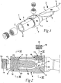
- Fig. 1
- is a perspective exploded view showing a basic body according to the invention exemplified in the form of a drill body, as well as two pairs of cages and sealing plugs for the same,
- Fig. 2
- is an exploded view shown partly in longitudinal section and partly in side view of the rear part of the drill body on an enlarged scale,
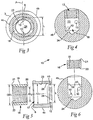
- Fig. 3
- is an enlarged cross section III-III in
Fig. 2 , - Fig. 4
- is an enlarged cross section IV-IV in
Fig. 2 , - Fig. 5
- is a detailed section showing the rear end portion of the drill body and a cage separated from the same, and
- Fig. 6
- is a cross section corresponding to
Fig. 4 , in which the cage is shown spaced-apart from the drill body. - In the drawings, a drill body is shown in the form of a completed, usable drill, which is manufactured in one single solid piece of material, preferably steel, and includes a rear part 1, which is spaced-apart from a
front part 2 via acollar 3. Similar to other drills, the drill body has an envelope surface in itsentirety 4 designated as well as front andrear ends tip 5, there are cutting inserts or cutting edges (not visible) for the chip removal and hole making. More precisely, two cutting edges are included to which chip flutes 7 are connected, which separate twobars 8. In this case, when the tool is a twist drill, thebars 8 as well as the chip flutes 7 are helicoidal and extend rearward from thetip 5 approximately up to thecollar 3. The envelope surface in its entirety designated 4 includes three different part surfaces, viz. apart surface 4a along thefront part 2, apart surface 4b along thecollar 3, as well as apart surface 4c along the rear part 1. In the last-mentionedpart surface 4c, aplane surface 9 is formed in order to enable transfer of torque to the drill body or clamp the same, when the rear part 1 is mounted in a machine attachment. - Inside the drill body, two
liquid ducts 10 are formed, the rear portions of which are visible inFigs. 2 and the front portions of which extend through thebars 8 of thefront part 2 of the drill body. More precisely, theducts 10 extend up tooutlets 11, one of which is visible inFig. 1 . To theducts 10, liquid can in this case be supplied via twoinlets part surface 4b, which is included in thecollar 3. To these inlets, either asealing plug 14 or a hose connection (not shown) could be coupled in order to afford the user the possibility of supplying the liquid either from behind or from the side, the unutilized inlet being closed by a plug. The sealing plugs as well as the hose connections are formed withmale threads 15 intended to be screwed into female threads, which surround or delimit theinlets - According to the invention, the female thread of the
individual inlet same reference designation 16, while the two seatings individually are designated 17 and 18, respectively. In the shown, preferred embodiment, the cages as well as the appurtenant seatings have a rotationally symmetrical basic shape. More precisely, the individual cage 16 (seeFig. 5 ) is ring-shaped and delimited by, on one hand, an external,smooth surface 19, which in this case is cylindrical and has an outer diameter OD1, and on the other hand two ring-shaped end surfaces 20, 21, which extend perpendicularly to the centre axis (lacks reference designation) of the cage. In the internal surface of the cage, afemale thread 22 is formed, which, such as previously has been mentioned, has a slightly conical shape, something which entails that the internal, ring-shapedend surface 20 of the cage is somewhat wider than theouter end surface 21. Theseating 17 as well as theseating 18 are delimited by, on one hand, an endless or rotationally symmetricalinner wall 23, and on the other hand a bottom 24. In both cases, theinner wall 23 is cylindrical and has a diameter ID1, which corresponds to the outer diameter OD1 of the cage in orderto seal against the cylindrical outside 19 of the individual cage. In this connection, the cage may be fixed in the appurtenant seating in various ways, which however always should ensure a seal so that liquid cannot pass between the outside of the cage and the inner wall of the seating. Tests made have shown that the cage may be glued into the seating, but also otherjoints are possible, e.g., shrinkage fits. - The
cage 16 is in practice manufactured of steel or another equivalent material, in which strong threads can be formed, in particular by turning. - As seen in
Figs. 2 and5 , thecage 16, which is mounted in therear seating 17 of the drill body, is shorter than the proper seating. In such a way, a space orgap 25 arises between theinner end 20 of the cage and the bottom 24 of the seating (which bottom is plane and circular), in which space theducts 10 open with full cross-sectional area. The twoliquid ducts 10 also open in theseating 18, but in this case in the cylindricalinner wall 23 of the seating, more precisely in the space, which is formed between theinner end surface 20 of theshort cage 16 and thebottom surface 24 of the longer seating. From this space in theseating 18, the ducts continue out in thebars 8 of thefront part 2 of the drill body. - As seen in
Fig. 3 , the twoducts 10 in the rear part 1 of the drill body are mutually situated in a diametrical plane P and spaced-apart at a distance L as measured between the radially outer portions of the insides of the ducts. InFig. 5 , it is seen that thecage 16 has an outer diameter OD1, which is somewhat greater than the distance L, which in turn is greater than the smallest diameter ID2 of thefemale thread 22. Due to thespace 25 between thecage 16 and the bottom 24 of the seating, the cage will however not block a free liquid flow into the ducts. - In
Fig. 5 , it is also shown that a ring-shapedshoulder surface 26 is formed in the cylindricalinner wall 23 of the seating, more precisely in order to serve as a stop, which determines the inner end position of the cage in the seating. See alsoFig. 6 . - By forming, in accordance with the invention, the female threads of the
inlets liquid feeding ducts 10 of the drill body. This affords in practice a plurality of advantages, one of which is that the ducts may be provided by pipe-drilling of one single piece of material. More precisely, the drill may be manufactured in the following way. - In a cylindrical blank, e.g., of steel, two parallel holes are drilled, suitably by pipe drills, which holes extend all the way between the front and rear ends of the blank, the holes being located fairly near the envelope surface of the blank in order to later end up in those parts of the
bars 8, which contain much material. In the next step, the blank is heated and is clamped with the rear part thereof fixed in a fixture, after which the front part is turned so that the drilled holes obtain the desired helix shape. In the next step, when the blank has cooled, forming of the chip flutes 7 in the front part of the blank follows, something which may take place by milling and/or grinding, as well as formation of theseatings - In the general application thereof to tool basic bodies, the invention affords the advantage that a thread-provided inlet to an internal duct of the basic body may optionally be placed in a suitable spot, without risk of liquid leakage in the threaded joint to, for instance, a hose connection or a plug. In addition, the invention affords substantial advantages in respect of the choice of material of the basic body. Thus, the basic body may be manufactured of a material, in which it is difficult or impossible to form strong threads. In other words, the cage having the female thread may be manufactured of steel or another equivalent material, while the basic body is manufactured of another material than steel, e.g., a composite material. In the application thereof to exactly drill bodies, the invention furthermore affords the advantage that the requisite liquid ducts may be pipe-drilled in a continuous blank irrespective of the number of ducts in the same, the completed drill body obtaining excellent properties in respect of dimensional accuracy and tolerances in comparison with such drills, which have to be assembled of two pre-machined parts.
- The invention is not solely limited to the embodiment described above and shown in the drawings. Thus, it is possible to apply the invention also to such basic bodies, which are not included in drills and which include another number of liquid conduit ducts than exactly two, e.g., only one. It is also applicable to drills having chip flutes and bars, which have another shape than exactly helicoidal, e.g., straight. It is even possible to manufacture the drill body or the basic bodybased on two different kinds of materials, viz. by metallurgically uniting two part bodies while forming an initial blank, which at a later stage is formed with through duct holes, chip flutes and seatings for the cages in the way described above. Generally, the invention may also be applied to any cutting tools other than exactly drills, e.g., milling cutter tools, turning tools, universal tools, etc.
Claims (4)
- Drill body for chip removing machining, comprising an internal duct (10) and an inlet (12, 13) including a female thread (22) for the supply of liquid to the duct, characterized in that the female thread (22) of the inlet (12, 13) is formed in a cage (16), which is inserted in a seating (17, 18) delimited by an endless inner wall (23) as well as a bottom (24), in which seating the duct (10) mouths, wherein the drill body includes an envelope surface (4) and front as well as rear ends (5, 6) between which a geometrical centre axis (C) extends, and in which the duct (10) extends from the front end (5) toward the rear end (6), characterized in that the inlet cage (16) is placed in a seating (17), which opens in the rear end (6), and extends in an extension of the duct (10), wherein the drill body includes two ducts (10), both of which are spaced-apart from the centre axis (C) and at least in a rear part (1) of the basic body mutually situated in a diametrical plane (P), wherein the bottom (24) of the seating (17) has a circular contour shape and a diameter (D1), which is greater than the greatest diametrical distance (L) between the insides of the two ducts (10), and wherein the cage (16) has an inner diameter (ID2), which is smaller than the greatest distance (L) between the insides of the ducts (10), and is shorter than the seating (17) such that, between the inner end (20) of the cage and the bottom (24) of the seating, a space (25) is delimited, in which the duct (10) opens with full cross-sectional area.
- Drill body according to claim 1, characterized in that the cage (16) and the basic body are manufactured of different materials.
- Drill body according to claim 2, characterized in that the cage (16) consists of steel.
- Drill body according to any one of the preceding claims, characterized in that the inner end (20) of the cage (16) is pressed against a ring-shaped shoulder surface (26), which is axially spaced apart from the bottom (24) of the seating (17, 18).
Applications Claiming Priority (1)
| Application Number | Priority Date | Filing Date | Title |
|---|---|---|---|
| SE0702759A SE531842C2 (en) | 2007-12-12 | 2007-12-12 | Basic body for chip separation tools |
Publications (3)
| Publication Number | Publication Date |
|---|---|
| EP2070617A1 EP2070617A1 (en) | 2009-06-17 |
| EP2070617B1 EP2070617B1 (en) | 2011-04-06 |
| EP2070617B2 true EP2070617B2 (en) | 2016-07-20 |
Family
ID=40348310
Family Applications (1)
| Application Number | Title | Priority Date | Filing Date |
|---|---|---|---|
| EP08169647.8A Active EP2070617B2 (en) | 2007-12-12 | 2008-11-21 | A basic body for tools for chip removing machining |
Country Status (9)
| Country | Link |
|---|---|
| US (1) | US7938048B2 (en) |
| EP (1) | EP2070617B2 (en) |
| JP (1) | JP5221312B2 (en) |
| KR (1) | KR101473012B1 (en) |
| CN (1) | CN101456087B (en) |
| AT (1) | ATE504378T1 (en) |
| DE (1) | DE602008005997D1 (en) |
| ES (1) | ES2363457T3 (en) |
| SE (1) | SE531842C2 (en) |
Families Citing this family (10)
| Publication number | Priority date | Publication date | Assignee | Title |
|---|---|---|---|---|
| TWI488251B (en) | 2012-10-19 | 2015-06-11 | Inotera Memories Inc | Over-head buffer device and wafer transfer system |
| CN105562789A (en) * | 2016-02-26 | 2016-05-11 | 太原重工股份有限公司 | Internal and external cooling dual-purpose drill rod |
| CN109715322B (en) * | 2016-09-29 | 2020-10-02 | 京瓷株式会社 | Cutting tool and method for manufacturing cut product using same |
| TWI606878B (en) * | 2016-12-06 | 2017-12-01 | 越有股份有限公司 | Boring fixture |
| JP6722153B2 (en) | 2017-07-28 | 2020-07-15 | 株式会社Subaru | Drill, drilling unit and drilling method |
| CN108296873A (en) * | 2018-04-02 | 2018-07-20 | 合肥市远大轴承锻造有限公司 | Cold conversion equipment in a kind of wind power bearing coil assembly drilling processing |
| KR101946199B1 (en) * | 2018-04-30 | 2019-02-08 | 전덕용 | A Machine Tools Having a Structure of Providing a Cutting Fluid through a Inner Path |
| JP7207983B2 (en) | 2018-12-10 | 2023-01-18 | 株式会社Subaru | Drills, drilling units and methods of making workpieces |
| JP7267766B2 (en) * | 2019-02-14 | 2023-05-02 | 株式会社Subaru | Rotary cutting tool, rotary cutting unit and method of making workpiece |
| JP2021186914A (en) | 2020-05-27 | 2021-12-13 | 株式会社Subaru | Hole-finish processing tool and manufacturing method for hole-finished product |
Citations (2)
| Publication number | Priority date | Publication date | Assignee | Title |
|---|---|---|---|---|
| US2955847A (en) † | 1957-01-08 | 1960-10-11 | Kennametal Inc | Cemented carbide drill rod pipe coupling having a replaceable wear element |
| US6565291B2 (en) † | 2000-08-18 | 2003-05-20 | Iscar, Ltd. | Cutting tool assembly |
Family Cites Families (17)
| Publication number | Priority date | Publication date | Assignee | Title |
|---|---|---|---|---|
| US3028772A (en) * | 1959-07-31 | 1962-04-10 | Carl W Mossberg | Liquid cooled counter-boring tool |
| GB1067975A (en) * | 1964-03-10 | 1967-05-10 | Sandvikens Jernverks Ab | Adapter device for percussion drill |
| US3333489A (en) * | 1965-05-06 | 1967-08-01 | Waukesha Cutting Tools Inc | Liquid cooled spade drills |
| US3364800A (en) * | 1965-05-07 | 1968-01-23 | Erickson Tool Co | Mist coolant spade drill |
| US3443819A (en) * | 1966-12-22 | 1969-05-13 | Erickson Tool Co | Drill chuck with coolant supply |
| US3561299A (en) * | 1969-05-06 | 1971-02-09 | Waukesha Cutting Tools Inc | Pulsating coolant adapter |
| US3791660A (en) * | 1973-01-09 | 1974-02-12 | Bendix Corp | Device for gripping, driving and supplying coolant to a cutting tool having coolant passages therein |
| JPH07111510B2 (en) * | 1988-08-22 | 1995-11-29 | 大日本スクリーン製造株式会社 | Image scanning recorder |
| JPH0256518U (en) * | 1988-10-14 | 1990-04-24 | ||
| US5037250A (en) * | 1990-01-08 | 1991-08-06 | Westinghouse Electric Corp. | Rotary tool holder |
| JP3764489B2 (en) * | 1991-07-15 | 2006-04-05 | ソニー株式会社 | Magnetic recording device |
| IL99297A (en) * | 1991-08-26 | 1995-11-27 | Iscar Ltd | Sealing bushing for the shaft for a work piece |
| JPH0520853U (en) * | 1991-08-30 | 1993-03-19 | 株式会社アツギユニシア | Drill unit structure of cutting machine |
| US6045300A (en) * | 1997-06-05 | 2000-04-04 | Antoun; Gregory S. | Tool holder with integral coolant passage and replaceable nozzle |
| US20030110781A1 (en) * | 2001-09-13 | 2003-06-19 | Zbigniew Zurecki | Apparatus and method of cryogenic cooling for high-energy cutting operations |
| GB0213019D0 (en) * | 2002-06-06 | 2002-07-17 | Clark John | Drilling attachment |
| US7090448B2 (en) * | 2004-08-03 | 2006-08-15 | Ford Motor Company | Tool holder assembly |
-
2007
- 2007-12-12 SE SE0702759A patent/SE531842C2/en not_active IP Right Cessation
-
2008
- 2008-11-21 EP EP08169647.8A patent/EP2070617B2/en active Active
- 2008-11-21 ES ES08169647T patent/ES2363457T3/en active Active
- 2008-11-21 AT AT08169647T patent/ATE504378T1/en not_active IP Right Cessation
- 2008-11-21 DE DE602008005997T patent/DE602008005997D1/en active Active
- 2008-11-25 US US12/277,348 patent/US7938048B2/en not_active Expired - Fee Related
- 2008-12-10 KR KR1020080125029A patent/KR101473012B1/en active IP Right Grant
- 2008-12-12 CN CN2008101867441A patent/CN101456087B/en not_active Expired - Fee Related
- 2008-12-12 JP JP2008317181A patent/JP5221312B2/en not_active Expired - Fee Related
Patent Citations (2)
| Publication number | Priority date | Publication date | Assignee | Title |
|---|---|---|---|---|
| US2955847A (en) † | 1957-01-08 | 1960-10-11 | Kennametal Inc | Cemented carbide drill rod pipe coupling having a replaceable wear element |
| US6565291B2 (en) † | 2000-08-18 | 2003-05-20 | Iscar, Ltd. | Cutting tool assembly |
Also Published As
| Publication number | Publication date |
|---|---|
| EP2070617A1 (en) | 2009-06-17 |
| SE531842C2 (en) | 2009-08-25 |
| KR20090063114A (en) | 2009-06-17 |
| SE0702759L (en) | 2009-06-13 |
| CN101456087B (en) | 2010-12-29 |
| JP5221312B2 (en) | 2013-06-26 |
| JP2009142984A (en) | 2009-07-02 |
| EP2070617B1 (en) | 2011-04-06 |
| DE602008005997D1 (en) | 2011-05-19 |
| ES2363457T3 (en) | 2011-08-04 |
| KR101473012B1 (en) | 2014-12-15 |
| ATE504378T1 (en) | 2011-04-15 |
| CN101456087A (en) | 2009-06-17 |
| US7938048B2 (en) | 2011-05-10 |
| US20090155006A1 (en) | 2009-06-18 |
Similar Documents
| Publication | Publication Date | Title |
|---|---|---|
| EP2070617B2 (en) | A basic body for tools for chip removing machining | |
| US8662800B2 (en) | Cutting head with coolant channel | |
| EP2979794A1 (en) | Three-bladed drill with cutting fluid supply hole | |
| US9604286B2 (en) | Drill | |
| US9238273B2 (en) | Milling tool | |
| EP2524755B2 (en) | A rotatable drilling tool as well as a basic body therefor | |
| JP5967583B2 (en) | Milling tools | |
| US20110268519A1 (en) | Method for Forming Through-Hole | |
| TW200902196A (en) | Method for manufacturing drill head | |
| KR102600217B1 (en) | Modular cutting tool body and method of manufacturing the same | |
| SE533277C2 (en) | Drill body and support strip for this | |
| WO2018206400A1 (en) | Drill body and drill | |
| KR20170135513A (en) | A Machine Tools Having a Structure of Providing a Cutting Fluid through a Inner Path | |
| JP2004283969A (en) | Deep hole cutting tool | |
| KR101946199B1 (en) | A Machine Tools Having a Structure of Providing a Cutting Fluid through a Inner Path | |
| JP2004283970A (en) | Deep hole cutting tool | |
| JP4047703B2 (en) | Deep hole cutting tool | |
| JP4272021B2 (en) | Deep hole cutting tool | |
| JP2004106065A (en) | Rotary cutting tool | |
| JP2004283971A (en) | Deep hole cutting tool |
Legal Events
| Date | Code | Title | Description |
|---|---|---|---|
| PUAI | Public reference made under article 153(3) epc to a published international application that has entered the european phase |
Free format text: ORIGINAL CODE: 0009012 |
|
| 17P | Request for examination filed |
Effective date: 20081121 |
|
| AK | Designated contracting states |
Kind code of ref document: A1 Designated state(s): AT BE BG CH CY CZ DE DK EE ES FI FR GB GR HR HU IE IS IT LI LT LU LV MC MT NL NO PL PT RO SE SI SK TR |
|
| AX | Request for extension of the european patent |
Extension state: AL BA MK RS |
|
| AKX | Designation fees paid |
Designated state(s): AT BE BG CH CY CZ DE DK EE ES FI FR GB GR HR HU IE IS IT LI LT LU LV MC MT NL NO PL PT RO SE SI SK TR |
|
| GRAP | Despatch of communication of intention to grant a patent |
Free format text: ORIGINAL CODE: EPIDOSNIGR1 |
|
| GRAS | Grant fee paid |
Free format text: ORIGINAL CODE: EPIDOSNIGR3 |
|
| GRAA | (expected) grant |
Free format text: ORIGINAL CODE: 0009210 |
|
| AK | Designated contracting states |
Kind code of ref document: B1 Designated state(s): AT BE BG CH CY CZ DE DK EE ES FI FR GB GR HR HU IE IS IT LI LT LU LV MC MT NL NO PL PT RO SE SI SK TR |
|
| REG | Reference to a national code |
Ref country code: GB Ref legal event code: FG4D |
|
| REG | Reference to a national code |
Ref country code: CH Ref legal event code: EP |
|
| REG | Reference to a national code |
Ref country code: IE Ref legal event code: FG4D |
|
| REF | Corresponds to: |
Ref document number: 602008005997 Country of ref document: DE Date of ref document: 20110519 Kind code of ref document: P |
|
| REG | Reference to a national code |
Ref country code: DE Ref legal event code: R096 Ref document number: 602008005997 Country of ref document: DE Effective date: 20110519 |
|
| REG | Reference to a national code |
Ref country code: NL Ref legal event code: VDEP Effective date: 20110406 |
|
| REG | Reference to a national code |
Ref country code: ES Ref legal event code: FG2A Ref document number: 2363457 Country of ref document: ES Kind code of ref document: T3 Effective date: 20110804 |
|
| PG25 | Lapsed in a contracting state [announced via postgrant information from national office to epo] |
Ref country code: SI Free format text: LAPSE BECAUSE OF FAILURE TO SUBMIT A TRANSLATION OF THE DESCRIPTION OR TO PAY THE FEE WITHIN THE PRESCRIBED TIME-LIMIT Effective date: 20110406 |
|
| LTIE | Lt: invalidation of european patent or patent extension |
Effective date: 20110406 |
|
| PG25 | Lapsed in a contracting state [announced via postgrant information from national office to epo] |
Ref country code: SE Free format text: LAPSE BECAUSE OF FAILURE TO SUBMIT A TRANSLATION OF THE DESCRIPTION OR TO PAY THE FEE WITHIN THE PRESCRIBED TIME-LIMIT Effective date: 20110406 Ref country code: PT Free format text: LAPSE BECAUSE OF FAILURE TO SUBMIT A TRANSLATION OF THE DESCRIPTION OR TO PAY THE FEE WITHIN THE PRESCRIBED TIME-LIMIT Effective date: 20110808 Ref country code: LT Free format text: LAPSE BECAUSE OF FAILURE TO SUBMIT A TRANSLATION OF THE DESCRIPTION OR TO PAY THE FEE WITHIN THE PRESCRIBED TIME-LIMIT Effective date: 20110406 Ref country code: NO Free format text: LAPSE BECAUSE OF FAILURE TO SUBMIT A TRANSLATION OF THE DESCRIPTION OR TO PAY THE FEE WITHIN THE PRESCRIBED TIME-LIMIT Effective date: 20110706 Ref country code: HR Free format text: LAPSE BECAUSE OF FAILURE TO SUBMIT A TRANSLATION OF THE DESCRIPTION OR TO PAY THE FEE WITHIN THE PRESCRIBED TIME-LIMIT Effective date: 20110406 |
|
| PG25 | Lapsed in a contracting state [announced via postgrant information from national office to epo] |
Ref country code: CY Free format text: LAPSE BECAUSE OF FAILURE TO SUBMIT A TRANSLATION OF THE DESCRIPTION OR TO PAY THE FEE WITHIN THE PRESCRIBED TIME-LIMIT Effective date: 20110406 Ref country code: AT Free format text: LAPSE BECAUSE OF FAILURE TO SUBMIT A TRANSLATION OF THE DESCRIPTION OR TO PAY THE FEE WITHIN THE PRESCRIBED TIME-LIMIT Effective date: 20110406 Ref country code: GR Free format text: LAPSE BECAUSE OF FAILURE TO SUBMIT A TRANSLATION OF THE DESCRIPTION OR TO PAY THE FEE WITHIN THE PRESCRIBED TIME-LIMIT Effective date: 20110707 Ref country code: IS Free format text: LAPSE BECAUSE OF FAILURE TO SUBMIT A TRANSLATION OF THE DESCRIPTION OR TO PAY THE FEE WITHIN THE PRESCRIBED TIME-LIMIT Effective date: 20110806 Ref country code: BE Free format text: LAPSE BECAUSE OF FAILURE TO SUBMIT A TRANSLATION OF THE DESCRIPTION OR TO PAY THE FEE WITHIN THE PRESCRIBED TIME-LIMIT Effective date: 20110406 Ref country code: FI Free format text: LAPSE BECAUSE OF FAILURE TO SUBMIT A TRANSLATION OF THE DESCRIPTION OR TO PAY THE FEE WITHIN THE PRESCRIBED TIME-LIMIT Effective date: 20110406 Ref country code: LV Free format text: LAPSE BECAUSE OF FAILURE TO SUBMIT A TRANSLATION OF THE DESCRIPTION OR TO PAY THE FEE WITHIN THE PRESCRIBED TIME-LIMIT Effective date: 20110406 |
|
| PG25 | Lapsed in a contracting state [announced via postgrant information from national office to epo] |
Ref country code: NL Free format text: LAPSE BECAUSE OF FAILURE TO SUBMIT A TRANSLATION OF THE DESCRIPTION OR TO PAY THE FEE WITHIN THE PRESCRIBED TIME-LIMIT Effective date: 20110406 |
|
| PLBI | Opposition filed |
Free format text: ORIGINAL CODE: 0009260 |
|
| PG25 | Lapsed in a contracting state [announced via postgrant information from national office to epo] |
Ref country code: EE Free format text: LAPSE BECAUSE OF FAILURE TO SUBMIT A TRANSLATION OF THE DESCRIPTION OR TO PAY THE FEE WITHIN THE PRESCRIBED TIME-LIMIT Effective date: 20110406 Ref country code: CZ Free format text: LAPSE BECAUSE OF FAILURE TO SUBMIT A TRANSLATION OF THE DESCRIPTION OR TO PAY THE FEE WITHIN THE PRESCRIBED TIME-LIMIT Effective date: 20110406 |
|
| PLAX | Notice of opposition and request to file observation + time limit sent |
Free format text: ORIGINAL CODE: EPIDOSNOBS2 |
|
| 26 | Opposition filed |
Opponent name: ISCAR LTD. Effective date: 20120105 |
|
| PG25 | Lapsed in a contracting state [announced via postgrant information from national office to epo] |
Ref country code: PL Free format text: LAPSE BECAUSE OF FAILURE TO SUBMIT A TRANSLATION OF THE DESCRIPTION OR TO PAY THE FEE WITHIN THE PRESCRIBED TIME-LIMIT Effective date: 20110406 Ref country code: SK Free format text: LAPSE BECAUSE OF FAILURE TO SUBMIT A TRANSLATION OF THE DESCRIPTION OR TO PAY THE FEE WITHIN THE PRESCRIBED TIME-LIMIT Effective date: 20110406 |
|
| REG | Reference to a national code |
Ref country code: DE Ref legal event code: R026 Ref document number: 602008005997 Country of ref document: DE Effective date: 20120105 |
|
| PLAF | Information modified related to communication of a notice of opposition and request to file observations + time limit |
Free format text: ORIGINAL CODE: EPIDOSCOBS2 |
|
| PG25 | Lapsed in a contracting state [announced via postgrant information from national office to epo] |
Ref country code: MC Free format text: LAPSE BECAUSE OF NON-PAYMENT OF DUE FEES Effective date: 20111130 |
|
| PLBB | Reply of patent proprietor to notice(s) of opposition received |
Free format text: ORIGINAL CODE: EPIDOSNOBS3 |
|
| REG | Reference to a national code |
Ref country code: IE Ref legal event code: MM4A |
|
| PG25 | Lapsed in a contracting state [announced via postgrant information from national office to epo] |
Ref country code: IE Free format text: LAPSE BECAUSE OF NON-PAYMENT OF DUE FEES Effective date: 20111121 |
|
| PG25 | Lapsed in a contracting state [announced via postgrant information from national office to epo] |
Ref country code: MT Free format text: LAPSE BECAUSE OF FAILURE TO SUBMIT A TRANSLATION OF THE DESCRIPTION OR TO PAY THE FEE WITHIN THE PRESCRIBED TIME-LIMIT Effective date: 20110406 |
|
| PG25 | Lapsed in a contracting state [announced via postgrant information from national office to epo] |
Ref country code: LU Free format text: LAPSE BECAUSE OF NON-PAYMENT OF DUE FEES Effective date: 20111121 |
|
| PG25 | Lapsed in a contracting state [announced via postgrant information from national office to epo] |
Ref country code: BG Free format text: LAPSE BECAUSE OF FAILURE TO SUBMIT A TRANSLATION OF THE DESCRIPTION OR TO PAY THE FEE WITHIN THE PRESCRIBED TIME-LIMIT Effective date: 20110706 |
|
| REG | Reference to a national code |
Ref country code: CH Ref legal event code: PL |
|
| PG25 | Lapsed in a contracting state [announced via postgrant information from national office to epo] |
Ref country code: CH Free format text: LAPSE BECAUSE OF NON-PAYMENT OF DUE FEES Effective date: 20121130 Ref country code: LI Free format text: LAPSE BECAUSE OF NON-PAYMENT OF DUE FEES Effective date: 20121130 |
|
| PG25 | Lapsed in a contracting state [announced via postgrant information from national office to epo] |
Ref country code: TR Free format text: LAPSE BECAUSE OF FAILURE TO SUBMIT A TRANSLATION OF THE DESCRIPTION OR TO PAY THE FEE WITHIN THE PRESCRIBED TIME-LIMIT Effective date: 20110406 |
|
| PG25 | Lapsed in a contracting state [announced via postgrant information from national office to epo] |
Ref country code: HU Free format text: LAPSE BECAUSE OF FAILURE TO SUBMIT A TRANSLATION OF THE DESCRIPTION OR TO PAY THE FEE WITHIN THE PRESCRIBED TIME-LIMIT Effective date: 20110406 |
|
| PLAB | Opposition data, opponent's data or that of the opponent's representative modified |
Free format text: ORIGINAL CODE: 0009299OPPO |
|
| R26 | Opposition filed (corrected) |
Opponent name: ISCAR LTD. Effective date: 20120105 |
|
| REG | Reference to a national code |
Ref country code: FR Ref legal event code: PLFP Year of fee payment: 8 |
|
| APBM | Appeal reference recorded |
Free format text: ORIGINAL CODE: EPIDOSNREFNO |
|
| APBP | Date of receipt of notice of appeal recorded |
Free format text: ORIGINAL CODE: EPIDOSNNOA2O |
|
| APAH | Appeal reference modified |
Free format text: ORIGINAL CODE: EPIDOSCREFNO |
|
| PGFP | Annual fee paid to national office [announced via postgrant information from national office to epo] |
Ref country code: ES Payment date: 20151014 Year of fee payment: 8 |
|
| APBU | Appeal procedure closed |
Free format text: ORIGINAL CODE: EPIDOSNNOA9O |
|
| PUAH | Patent maintained in amended form |
Free format text: ORIGINAL CODE: 0009272 |
|
| STAA | Information on the status of an ep patent application or granted ep patent |
Free format text: STATUS: PATENT MAINTAINED AS AMENDED |
|
| 27A | Patent maintained in amended form |
Effective date: 20160720 |
|
| AK | Designated contracting states |
Kind code of ref document: B2 Designated state(s): AT BE BG CH CY CZ DE DK EE ES FI FR GB GR HR HU IE IS IT LI LT LU LV MC MT NL NO PL PT RO SE SI SK TR |
|
| REG | Reference to a national code |
Ref country code: DE Ref legal event code: R102 Ref document number: 602008005997 Country of ref document: DE |
|
| REG | Reference to a national code |
Ref country code: FR Ref legal event code: PLFP Year of fee payment: 9 |
|
| PG25 | Lapsed in a contracting state [announced via postgrant information from national office to epo] |
Ref country code: ES Free format text: LAPSE BECAUSE OF FAILURE TO SUBMIT A TRANSLATION OF THE DESCRIPTION OR TO PAY THE FEE WITHIN THE PRESCRIBED TIME-LIMIT Effective date: 20160720 |
|
| REG | Reference to a national code |
Ref country code: FR Ref legal event code: PLFP Year of fee payment: 10 |
|
| REG | Reference to a national code |
Ref country code: FR Ref legal event code: PLFP Year of fee payment: 11 |
|
| PGFP | Annual fee paid to national office [announced via postgrant information from national office to epo] |
Ref country code: DE Payment date: 20191105 Year of fee payment: 12 |
|
| PGFP | Annual fee paid to national office [announced via postgrant information from national office to epo] |
Ref country code: FR Payment date: 20191023 Year of fee payment: 12 Ref country code: IT Payment date: 20191108 Year of fee payment: 12 |
|
| PGFP | Annual fee paid to national office [announced via postgrant information from national office to epo] |
Ref country code: GB Payment date: 20191122 Year of fee payment: 12 |
|
| REG | Reference to a national code |
Ref country code: DE Ref legal event code: R119 Ref document number: 602008005997 Country of ref document: DE |
|
| GBPC | Gb: european patent ceased through non-payment of renewal fee |
Effective date: 20201121 |
|
| PG25 | Lapsed in a contracting state [announced via postgrant information from national office to epo] |
Ref country code: IT Free format text: LAPSE BECAUSE OF NON-PAYMENT OF DUE FEES Effective date: 20201121 Ref country code: FR Free format text: LAPSE BECAUSE OF NON-PAYMENT OF DUE FEES Effective date: 20201130 |
|
| PG25 | Lapsed in a contracting state [announced via postgrant information from national office to epo] |
Ref country code: GB Free format text: LAPSE BECAUSE OF NON-PAYMENT OF DUE FEES Effective date: 20201121 Ref country code: DE Free format text: LAPSE BECAUSE OF NON-PAYMENT OF DUE FEES Effective date: 20210601 |