EP2070175B1 - Verfahren zum betrieb einer mit dem versorgungsnetz verbundenen windturbine bei netzstörungen, windturbine und windenergieanlage - Google Patents
Verfahren zum betrieb einer mit dem versorgungsnetz verbundenen windturbine bei netzstörungen, windturbine und windenergieanlage Download PDFInfo
- Publication number
- EP2070175B1 EP2070175B1 EP07801386.9A EP07801386A EP2070175B1 EP 2070175 B1 EP2070175 B1 EP 2070175B1 EP 07801386 A EP07801386 A EP 07801386A EP 2070175 B1 EP2070175 B1 EP 2070175B1
- Authority
- EP
- European Patent Office
- Prior art keywords
- wind turbine
- operating
- utility grid
- active
- frequency
- Prior art date
- Legal status (The legal status is an assumption and is not a legal conclusion. Google has not performed a legal analysis and makes no representation as to the accuracy of the status listed.)
- Revoked
Links
Images


Classifications
-
- H—ELECTRICITY
- H02—GENERATION; CONVERSION OR DISTRIBUTION OF ELECTRIC POWER
- H02J—CIRCUIT ARRANGEMENTS OR SYSTEMS FOR SUPPLYING OR DISTRIBUTING ELECTRIC POWER; SYSTEMS FOR STORING ELECTRIC ENERGY
- H02J3/00—Circuit arrangements for ac mains or ac distribution networks
- H02J3/38—Arrangements for parallely feeding a single network by two or more generators, converters or transformers
- H02J3/381—Dispersed generators
-
- H—ELECTRICITY
- H02—GENERATION; CONVERSION OR DISTRIBUTION OF ELECTRIC POWER
- H02J—CIRCUIT ARRANGEMENTS OR SYSTEMS FOR SUPPLYING OR DISTRIBUTING ELECTRIC POWER; SYSTEMS FOR STORING ELECTRIC ENERGY
- H02J2300/00—Systems for supplying or distributing electric power characterised by decentralized, dispersed, or local generation
- H02J2300/20—The dispersed energy generation being of renewable origin
- H02J2300/28—The renewable source being wind energy
-
- Y—GENERAL TAGGING OF NEW TECHNOLOGICAL DEVELOPMENTS; GENERAL TAGGING OF CROSS-SECTIONAL TECHNOLOGIES SPANNING OVER SEVERAL SECTIONS OF THE IPC; TECHNICAL SUBJECTS COVERED BY FORMER USPC CROSS-REFERENCE ART COLLECTIONS [XRACs] AND DIGESTS
- Y02—TECHNOLOGIES OR APPLICATIONS FOR MITIGATION OR ADAPTATION AGAINST CLIMATE CHANGE
- Y02E—REDUCTION OF GREENHOUSE GAS [GHG] EMISSIONS, RELATED TO ENERGY GENERATION, TRANSMISSION OR DISTRIBUTION
- Y02E10/00—Energy generation through renewable energy sources
- Y02E10/70—Wind energy
- Y02E10/76—Power conversion electric or electronic aspects
Definitions
- the invention relates to a method for operating a wind turbine connected to a utility grid during a utility grid disturbance, wind turbine and wind park.
- European patent no. EP 1 493 921 discloses an example of a method for controlling the phase angle between active and reactive power in dependency of measured voltage level.
- the document WO 01 86143 discloses a method for operating a wind turbine according the preamble of claim 1.
- the invention provides a method for operating a wind turbine connected to a utility grid during a utility grid disturbance, said method comprises the steps of:
- active and/or reactive current is supplied to the utility grid connection point of the wind turbine by other types of sources beyond the wind turbine. Her eby it is ensured that power produced by other types of sources is controllable supplied to the utility grid during said grid disturbance.
- Other types of sources can e.g. be capacitor banks, diesel generators etc.
- controlling of active and reactive current is executed after at least one control algorithm.
- said control can be done e.g. on the basis of actual measured parameters producing an optimal control of said currents.
- control algorithm is implemented in at least one PID controller.
- i Q is the active current
- i D is the reactive current.
- controlling of the wind turbine can be adapted to fulfil many specific demands in a flexible way, depending of the coefficients of said control algorithm. Furthermore it is ensured that the control algorithm can be adapted to fulfil the compliance with various grid codes.
- values of drive train oscillations ⁇ ⁇ are additional control parameters of said active current control.
- said active current is controlled in dependency of the frequency deviation outside of a frequency dead band comprising a reference frequency.
- said reactive current is controlled in dependency of the voltage deviation outside of a voltage dead band comprising a reference voltage.
- said frequency dead band is in the range of ⁇ 4 ⁇ from said reference frequency e.g. 49.8 Hz to 50.2 Hz in a 50 Hz system.
- said frequency dead band comply with existing grid codes.
- said voltage dead band is in the range of 100% to 85% of said reference voltage, preferably in the range of 100% to 90% of said reference voltage.
- said reference values of voltage and/or frequency are utility grid nominal values e.g. a nominal frequency value of 50 or 60 Hz.
- the invention also relates to a wind turbine connected to a utility grid during a utility grid disturbance comprising control means for controlling the wind turbine with a method according to any of the preceding claims.
- said wind turbine comprise a variable speed generator and at least one converter system to control active and/or reactive current supplied to the utility grid.
- the invention also relates to a wind park comprising at least two wind turbines.
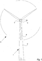
- Fig. 1 illustrates a modern wind turbine 1 with a tower 2 and a wind turbine nacelle 3 positioned on top of the tower.
- the wind turbine rotor comprising at least one blade such as three wind turbine blades 5 as illustrated, is connected to the hub 4 through pitch mechanisms 6.
- Each pitch mechanism includes a blade bearing and pitch actuating means which allows the blade to pitch.
- the pitch process is controlled by a pitch controller.
- wind over a certain level will activate the rotor and allow it to rotate in a perpendicular direction to the wind.
- the rotation movement is converted to electric power which usually is supplied to the utility grid as will be known by skilled persons within the area.
- Fig. 2 illustrates schematically one preferred embodiment of a wind turbine with a control system, or controller, for controlling the operation of a wind turbine.
- Data of the wind turbine 1 are measured e.g. with sensor means 7 located in the nacelle 3 such as pitch position sensors, blade load sensors, rotor azimuth sensors, tower acceleration sensors etc.
- the measured sensor data are supplied to computing means 8 in order to convert the data to feedback signals.
- the feedback signals are used in various control systems e.g. the pitch control system 9a for controlling the pitch angle by establishing control values for controlling said at least one wind turbine blade 5.
- sensor means can comprise means for measuring parameters of components or systems connected to said wind turbine such as actual supplied power and/or current to a utility grid, actual frequency of the grid or like. Said measured parameters are also supplied to computing means 8 in order to convert the data to feedback signals used for the control of e.g. a wind turbine converter control system.
- the computing means 8 preferably includes a microprocessor and computer storage means for continuous control of the said feedback signal. Since many grid disturbances are caused by short circuits somewhere in the utility grid resulting in excessive power consumption (dissipation), the grid disturbance may influence both the voltage level in PCC and the frequency of said grid.
- the generated active power/current from the turbine helps in stabilizing the utility grid frequency whereas the voltage in the PCC is mainly influenced by the reactive power/current generated by the wind turbine/wind park.
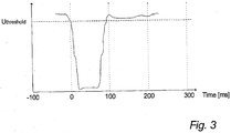
- Fig. 3 illustrates an example of a voltage vs. time curve illustrating a realistic grid fault event.
- the grid disturbance may influence both the voltage level in PCC and the frequency of said grid.
- the generated active power/current from the turbine helps in stabilizing the utility grid frequency whereas the voltage in the PCC is mainly influenced by the reactive power/current generated by the wind turbine/wind park.
- time 0 when the voltage drops to below a U threshold of e.g. 85% of nominal.
- the grid fault lasts approx. 100 ms as indicated on the figure. It is important for the operation of a wind turbine that it is able to stay connected to the grid during said fault event in order to continuously supply power to the grid.
- Fig. 4 illustrates for one embodiment of the invention the power control system during normal operation i.e. without utility grid disturbance.
- Said power control system is preferably implemented on a microprocessor based system, executing preprogrammed algorithms for regulating a set of output parameters on the basis of sets of input parameters.
- the active power control system 10 is operated in the following way:
- the coefficients for said first 12 and second 13 controllers are chosen as to give a desired active power control system 10 response on the basis of its input.
- a similar control structure 11 applies to the control of reactive power, but with another set of control parameters e.g. the actual supplied reactive power Q, the demanded reactive power Q* and the measured reactive current supplied to the grid id.
- Fig. 5 illustrates for one embodiment of the invention the control structure for controlling the active and reactive current respectively supplied to the grid during a utility grid disturbance.
- controlling active current is done in dependency of the frequency deviation from a reference frequency and controlling reactive current is done in dependency of the voltage deviation from a reference voltage.
- Frequency and voltage parameters are therefore used as control parameters to the current control system during said disturbance.
- the coefficients for said first 14 and second 15 controllers are chosen as to give a desired active current control system 16 response on the basis of its input.
- a similar control structure 17 applies to the control of reactive current, but with another set of control parameters e.g. the actual grid voltage v, a reference grid voltage v* and the measured reactive current supplied to the grid id.
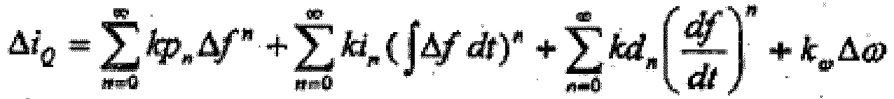
- the control algorithm for regulating the active current during a utility grid disturbance furthermore comprises a sequence as to damp the mechanical oscillations in the drive train triggered by said grid disturbance.
- said first controller 14 receives an input signal representing said oscillations in the drive train.
- Figs. 7a-e illustrate simulated responses for different embodiments of the invented current controller under influence of a simulated grid disturbance as shown in fig. 6 .
- Table 1 and table 2 lists the coefficients for said first controllers 14, 18 for different embodiments of the invention.
- Table 1 shows the coefficients for the active current first controller 14 whereas table 2 shows the coefficients for the reactive current first controller 18.
- the present invention relates to any type of wind turbine comprising a generator and one or more converter systems to control active and reactive power and/or active and reactive current supply to a utility grid such as a full scale converter for a synchronous- or asynchronous generator or a rotor side converter for a double-fed asynchron generator.
Claims (15)
- Verfahren zum Betreiben einer Windturbine (1), verbunden mit einem Energieversorgungsnetz während einer Störung des Energieversorgungsnetzes, das Verfahren umfassend die Schritte:Steuern erzeugten Wirkstroms von der Turbine in Abhängigkeit von der Frequenzabweichung von einer Bezugsfrequenz, undgekennzeichnet dadurch, dass dieses weiterhin die Schritte umfasst:Steuern erzeugten Wirkstroms von der Turbine in Abhängigkeit von der Spannungsabweichung von einer Bezugsspannung.
- Verfahren zum Betreiben einer Windturbine nach Anspruch 1, wobei Wirkstrom und/oder Blindstrom zu dem Energieversorgungsnetz-Verbindungspunkt der Windturbine mittels anderer Arten von Quellen außer der Windturbine geliefert wird.
- Verfahren zum Betreiben einer Windturbine nach Ansprüchen 1 oder 2, wobei das Steuern von Wirkstrom und Blindstrom nach zumindest einem Steueralgorithmus ausgeführt wird.
- Verfahren zum Betreiben einer Windturbine nach Anspruch 3, wobei der Steueralgorithmus in zumindest eine PID-Steuervorrichtung implementiert wird.
- Verfahren zum Betreiben einer Windturbine nach einem der Ansprüche 3 oder 4, wobei der Steueralgorithmus ist:


- Verfahren zum Betreiben einer Windturbine nach einem der vorhergehenden Ansprüche, wobei die Werte von Antriebsstrangoszillationen Δω zusätzliche Steuerparameter der Wirkstromsteuerung sind.
- Verfahren zum Betreiben einer Windturbine nach einem der vorhergehenden Ansprüche, wobei der Steueralgorithmus ist:

- Verfahren zum Betreiben einer Windturbine nach einem der vorhergehenden Ansprüche, wobei der Wirkstrom in Abhängigkeit von der Frequenzabweichung außerhalb eines Frequenzunempfindlichkeitsbereiches, der eine Bezugsfrequenz umfasst, gesteuert wird.
- Verfahren zum Betreiben einer Windturbine nach einem der vorhergehenden Ansprüche, wobei der Blindstrom in Abhängigkeit von der Spannungsabweichung außerhalb eines Spannungsunempfindlichkeitsbereiches, der eine Bezugsspannung umfasst, gesteuert wird.
- Verfahren zum Betreiben einer Windturbine nach einem der vorhergehenden Ansprüche, wobei der Frequenzunempfindlichkeitsbereich sich in dem Bereich von +/- 4‰ von der Bezugsfrequenz befindet, z.B. 49,8 Hz bis 50,2 Hz in einem 50 Hz System.
- Verfahren zum Betreiben einer Windturbine nach einem der vorhergehenden Ansprüche, wobei der Spannungsunempfindlichkeitsbereich sich in dem Bereich von 100% bis 85% der Bezugsspannung, vorzugsweise in dem Bereich von 100% bis 90% der Bezugsspannung, befindet.
- Verfahren zum Betreiben einer Windturbine nach einem der vorhergehenden Ansprüche, wobei die Bezugswerte der Spannung und/oder Frequenz Nominalwerte des Energieversorgungsnetzes sind, z.B. ein nominaler Frequenzwert von 50 oder 60 Hz.
- Windturbine, verbunden mit einem Energieversorgungsnetz während einer Störung des Energieversorgungsnetzes, umfassend Steuermittel zum Steuern der Windturbine mit einem Verfahren nach einem der vorhergehenden Ansprüche.
- Windturbine nach Anspruch 13, umfassend einen variablen Geschwindigkeitsgenerator und zumindest ein Wandlersystem zum Steuern von Wirkstrom und/oder Blindstrom, der zu dem Energieversorgungsnetz geliefert wird.
- Windpark umfassend zumindest zwei Turbinen nach Anspruch 13 und/oder 14.
Applications Claiming Priority (2)
| Application Number | Priority Date | Filing Date | Title |
|---|---|---|---|
| DKPA200601275 | 2006-10-02 | ||
| PCT/DK2007/000423 WO2008040350A2 (en) | 2006-10-02 | 2007-10-02 | Method for operating a wind turbine connected to a utility grid during utility grid disturbance, wind turbine and wind park |
Publications (2)
| Publication Number | Publication Date |
|---|---|
| EP2070175A2 EP2070175A2 (de) | 2009-06-17 |
| EP2070175B1 true EP2070175B1 (de) | 2016-12-07 |
Family
ID=39209157
Family Applications (1)
| Application Number | Title | Priority Date | Filing Date |
|---|---|---|---|
| EP07801386.9A Revoked EP2070175B1 (de) | 2006-10-02 | 2007-10-02 | Verfahren zum betrieb einer mit dem versorgungsnetz verbundenen windturbine bei netzstörungen, windturbine und windenergieanlage |
Country Status (9)
| Country | Link |
|---|---|
| US (1) | US8041466B2 (de) |
| EP (1) | EP2070175B1 (de) |
| CN (1) | CN101542864A (de) |
| AU (1) | AU2007304636B2 (de) |
| BR (1) | BRPI0717267A2 (de) |
| CA (1) | CA2664924C (de) |
| ES (1) | ES2611131T3 (de) |
| MX (1) | MX2009002659A (de) |
| WO (1) | WO2008040350A2 (de) |
Families Citing this family (23)
| Publication number | Priority date | Publication date | Assignee | Title |
|---|---|---|---|---|
| DE102006054870A1 (de) | 2006-11-20 | 2008-06-12 | Repower Systems Ag | Windenergieanlage mit Gegensystemregelung und Betriebsverfahren |
| WO2010000663A1 (en) * | 2008-06-30 | 2010-01-07 | Vestas Wind Systems A/S | Method and system for controlling a wind power plant comprising a number of wind turbine generators |
| DE102009014012B4 (de) | 2009-03-23 | 2014-02-13 | Wobben Properties Gmbh | Verfahren zum Betreiben einer Windenergieanlage |
| CN101981310B (zh) * | 2009-06-05 | 2013-10-30 | 三菱重工业株式会社 | 风力发电装置及其控制方法、风力发电系统 |
| ES2382631B1 (es) * | 2009-09-03 | 2013-05-03 | Gamesa Innovation & Technology, S.L. | Metodos y sistemas de control de aerogeneradores |
| US9478987B2 (en) * | 2009-11-10 | 2016-10-25 | Siemens Aktiengesellschaft | Power oscillation damping employing a full or partial conversion wind turbine |
| DE102010021070A1 (de) * | 2010-05-19 | 2011-11-24 | Siemens Aktiengesellschaft | Verfahren zur Regelung der Stabilität eines elektrichen Versorgungsnetzwerks |
| US20120104753A1 (en) | 2010-10-29 | 2012-05-03 | Mitsubishi Heavy Industries, Ltd. | Control system of wind power generator, wind farm, and method for controlling wind power generator |
| US8405247B2 (en) * | 2010-12-16 | 2013-03-26 | General Electric Company | Method and apparatus for control of fault-induced delayed voltage recovery (FIDVR) with photovoltaic and other inverter-based devices |
| US20120209548A1 (en) * | 2011-02-10 | 2012-08-16 | General Electric Company | Monitoring occurrence of transmission and distribution grid code event by power consumption device |
| WO2012136843A1 (en) * | 2011-04-08 | 2012-10-11 | Sma Solar Technology Ag | Optimized load management |
| CN103827483B (zh) * | 2011-09-30 | 2016-08-17 | 维斯塔斯风力系统集团公司 | 包含电站损失的快速回流控制 |
| EP2607692B1 (de) * | 2011-12-22 | 2015-04-15 | Siemens Aktiengesellschaft | Verfahren zur Bestimmung eines Spannungsbegrenzungsbereichs |
| EP2645530B1 (de) * | 2012-03-27 | 2018-08-15 | Siemens Aktiengesellschaft | Verfahren zur Steuerung einer Windfarm, Windfarmregler, Windfarm, computerlesbares Medium und Programmelement |
| JP2013221404A (ja) * | 2012-04-12 | 2013-10-28 | Yaskawa Electric Corp | 発電装置および発電システム |
| DE102014016665A1 (de) * | 2014-11-12 | 2016-05-12 | Senvion Gmbh | Windenergieanlage und Verfahren zum Betreiben einer Windenergieanlage |
| WO2017202428A1 (en) * | 2016-05-25 | 2017-11-30 | Vestas Wind Systems A/S | Operating a wind turbine generator during an abnormal grid event |
| DE102016120700A1 (de) | 2016-10-28 | 2018-05-03 | Wobben Properties Gmbh | Verfahren zum Betreiben einer Windenergieanlage |
| CN109424502B (zh) * | 2017-09-04 | 2022-05-27 | 通用电气公司 | 用于防止风力涡轮电力系统的电压骤降的系统及方法 |
| DE102018125529A1 (de) * | 2018-10-15 | 2020-04-16 | Wobben Properties Gmbh | Dynamisches Windkraftwerk |
| EP3734799A1 (de) * | 2019-05-02 | 2020-11-04 | Siemens Gamesa Renewable Energy A/S | Betrieb einer windturbinde und zugehörige methode |
| CN111082471B (zh) * | 2019-12-04 | 2022-09-09 | 中国电力科学研究院有限公司 | 一种稳态下的逆变器有功无功电流动态分配方法及系统 |
| US11671039B2 (en) | 2020-12-10 | 2023-06-06 | General Electric Renovables Espana, S.L. | System and method for operating an asynchronous inverter-based resource as a virtual synchronous machine to provide grid-forming control thereof |
Citations (6)
| Publication number | Priority date | Publication date | Assignee | Title |
|---|---|---|---|---|
| DE3311299A1 (de) | 1983-03-28 | 1984-10-04 | Siemens AG, 1000 Berlin und 8000 München | Verfahren und vorrichtung zum stabilisieren von frequenz und spannung eines aus einem antriebsaggregat gespeisten netzes |
| US6137187A (en) | 1997-08-08 | 2000-10-24 | Zond Energy Systems, Inc. | Variable speed wind turbine generator |
| WO2001086143A1 (de) | 2000-05-11 | 2001-11-15 | Aloys Wobben | Verfahren zum betreiben einer windenergienanlage sowie windenergieanlage |
| EP1493921A1 (de) | 2001-04-24 | 2005-01-05 | Aloys Wobben | Verfahren zum Betreiben einer Windenergieanlage |
| WO2005031160A2 (de) | 2003-09-25 | 2005-04-07 | Repower Systems Ag | Windenergieanlage mit einem blindleistungsmodul zur netzstützung und verfahren dazu |
| US20060066111A1 (en) | 2004-09-30 | 2006-03-30 | Shashikanth Suryanarayanan | Vibration damping system and method for variable speed wind turbines |
Family Cites Families (13)
| Publication number | Priority date | Publication date | Assignee | Title |
|---|---|---|---|---|
| US4189648A (en) * | 1978-06-15 | 1980-02-19 | United Technologies Corporation | Wind turbine generator acceleration control |
| JP3547355B2 (ja) | 1999-12-28 | 2004-07-28 | 株式会社日立製作所 | 電力変換システム |
| NO20001641L (no) | 2000-03-29 | 2001-10-01 | Abb Research Ltd | Vindkraftanlegg |
| EP1284045A1 (de) * | 2000-05-23 | 2003-02-19 | Vestas Wind System A/S | Windturbine variabler geschwindigkeit mit einem matrixwandler |
| DE10059018C2 (de) | 2000-11-28 | 2002-10-24 | Aloys Wobben | Windenergieanlage bzw. Windpark bestehend aus einer Vielzahl von Windenergieanlagen |
| US6876176B2 (en) * | 2000-12-02 | 2005-04-05 | Ford Global Technologies, Llc | Toroidally wound induction motor-generator with selectable number of poles and vector control |
| DE50214671D1 (de) | 2001-04-20 | 2010-11-04 | Baw Gmbh | Verfahren zum betreiben einer windenergieanlage |
| US6858953B2 (en) * | 2002-12-20 | 2005-02-22 | Hawaiian Electric Company, Inc. | Power control interface between a wind farm and a power transmission system |
| EP1467463B1 (de) | 2003-04-09 | 2016-12-21 | General Electric Company | Windpark und Verfahren zum Betrieb des Windparks |
| US6924565B2 (en) | 2003-08-18 | 2005-08-02 | General Electric Company | Continuous reactive power support for wind turbine generators |
| WO2005025026A1 (de) * | 2003-09-03 | 2005-03-17 | Repower Systems Ag | Verfahren zum betrieb bzw. regelung einer windenergieanlage sowie verfahren zur bereitstellung von primärrefelleistung mit windenergieanlagen |
| BRPI0418588B1 (pt) | 2004-03-12 | 2021-10-13 | General Electric Company | Método para operar um conversor de frequência de um gerador e uma turbina de energia eólica apresentando um gerador operado de acordo com o método |
| ES2277724B1 (es) * | 2005-02-23 | 2008-06-16 | GAMESA INNOVATION & TECHNOLOGY, S.L. | Procedimiento y dispositivo para inyectar intensidad reactiva durante un hueco de tension de red. |
-
2007
- 2007-10-02 AU AU2007304636A patent/AU2007304636B2/en not_active Ceased
- 2007-10-02 CA CA2664924A patent/CA2664924C/en not_active Expired - Fee Related
- 2007-10-02 CN CNA2007800370524A patent/CN101542864A/zh active Pending
- 2007-10-02 MX MX2009002659A patent/MX2009002659A/es active IP Right Grant
- 2007-10-02 WO PCT/DK2007/000423 patent/WO2008040350A2/en active Application Filing
- 2007-10-02 EP EP07801386.9A patent/EP2070175B1/de not_active Revoked
- 2007-10-02 BR BRPI0717267 patent/BRPI0717267A2/pt not_active Application Discontinuation
- 2007-10-02 ES ES07801386.9T patent/ES2611131T3/es active Active
-
2009
- 2009-04-02 US US12/417,365 patent/US8041466B2/en not_active Expired - Fee Related
Patent Citations (6)
| Publication number | Priority date | Publication date | Assignee | Title |
|---|---|---|---|---|
| DE3311299A1 (de) | 1983-03-28 | 1984-10-04 | Siemens AG, 1000 Berlin und 8000 München | Verfahren und vorrichtung zum stabilisieren von frequenz und spannung eines aus einem antriebsaggregat gespeisten netzes |
| US6137187A (en) | 1997-08-08 | 2000-10-24 | Zond Energy Systems, Inc. | Variable speed wind turbine generator |
| WO2001086143A1 (de) | 2000-05-11 | 2001-11-15 | Aloys Wobben | Verfahren zum betreiben einer windenergienanlage sowie windenergieanlage |
| EP1493921A1 (de) | 2001-04-24 | 2005-01-05 | Aloys Wobben | Verfahren zum Betreiben einer Windenergieanlage |
| WO2005031160A2 (de) | 2003-09-25 | 2005-04-07 | Repower Systems Ag | Windenergieanlage mit einem blindleistungsmodul zur netzstützung und verfahren dazu |
| US20060066111A1 (en) | 2004-09-30 | 2006-03-30 | Shashikanth Suryanarayanan | Vibration damping system and method for variable speed wind turbines |
Non-Patent Citations (7)
| Title |
|---|
| "Grid Code - High and Extra High Voltage", E.ON, 1 April 2006 (2006-04-01), pages 1 - 46, XP055418455 |
| "PID Controller", WIKIPEDIA, 5 September 2017 (2017-09-05), pages 1 - 17, XP055418467 |
| "Wind Energy Handbook", 2001, article T. BURTON ET AL. |
| "Wind Turbines Connected to Grids with Voltages above 100 kV - Technical regulations for the properties and the regulation of wind turbines", EKRAFT SYSTEM REGULATION TF 3.2.5, 3 December 2004 (2004-12-03), pages 1 - 34, XP055418462 |
| A. D. HANSEN ET AL.: "Centralised power control of wind farm with doubly fed induction genera- tors", RENEWABLE ENERGY, vol. 31, 2006, pages 935 - 951, XP002471696, [retrieved on 20050810] |
| E. A. BOSSANYI ET AL.: "The Design of Closed Loop Controllers for Wind Turbines", WIND ENERG., vol. 3, 2000, pages 149 - 163, XP007908706 |
| P. SØRENSEN ET AL.: "Wind farm models and control strategies", RISO REPORT, August 2005 (2005-08-01), Roskilde, Denmark, pages 1 - 63, XP055262131 |
Also Published As
| Publication number | Publication date |
|---|---|
| US8041466B2 (en) | 2011-10-18 |
| MX2009002659A (es) | 2009-06-05 |
| CA2664924A1 (en) | 2008-04-10 |
| AU2007304636B2 (en) | 2010-10-14 |
| AU2007304636A1 (en) | 2008-04-10 |
| CA2664924C (en) | 2016-07-05 |
| EP2070175A2 (de) | 2009-06-17 |
| ES2611131T3 (es) | 2017-05-05 |
| CN101542864A (zh) | 2009-09-23 |
| BRPI0717267A2 (pt) | 2015-02-03 |
| WO2008040350A3 (en) | 2008-06-19 |
| US20090254223A1 (en) | 2009-10-08 |
| WO2008040350A2 (en) | 2008-04-10 |
Similar Documents
| Publication | Publication Date | Title |
|---|---|---|
| EP2070175B1 (de) | Verfahren zum betrieb einer mit dem versorgungsnetz verbundenen windturbine bei netzstörungen, windturbine und windenergieanlage | |
| CN110446853B (zh) | 用于管理风力涡轮机塔架的扭转振荡的系统和方法 | |
| EP2061967B1 (de) | Verfahren zur steuerung einer mit dem versorgungsnetz verbundenen windturbine, windturbine und windenergiepark | |
| Bossanyi et al. | Validation of individual pitch control by field tests on two-and three-bladed wind turbines | |
| US7948104B2 (en) | Method of operating a wind turbine with pitch control, a wind turbine and a cluster of wind turbines | |
| EP3504425B1 (de) | Dämpfung von windturbinenturmschwingungen | |
| US8793027B2 (en) | Power curtailment of wind turbines | |
| EP3318751B1 (de) | Dämpfung mechanischer schwingungen einer windturbine | |
| US7851934B2 (en) | Method for controlling a wind turbine connected to the utility grid, wind turbine and wind park | |
| US20150369214A1 (en) | Model based controller for a wind turbine generator | |
| US20130187383A1 (en) | System and method for operating a wind turbine using adaptive reference variables | |
| US20100072751A1 (en) | Variable Speed Wind Turbine, A Resonant Control System, A Method Of Operating A Variable Speed Wind Turbine, Use Of A Resonant Control System And Use Of A Method In A Variable Speed Wind Turbine | |
| EP2500562A2 (de) | Verfahren und System zur Verringerung der in Windturbinen durch Windasymmetrien entstehenden Belastungen | |
| US20090224542A1 (en) | Wind turbine operational method | |
| CN114286892A (zh) | 来自风力涡轮机系统的快速频率支持 | |
| KR20110009072A (ko) | 풍력 발전 장치 및 그 제어 방법 | |
| CN105794067A (zh) | 具有改进的上升时间的风力发电站 | |
| CN103052794B (zh) | 风力发电装置的控制装置、风力发电系统及风力发电装置的控制方法 | |
| EP2113659B1 (de) | Verfahren zum Betreiben einer Windturbine zur Minimierung der Schwingungen des Turms | |
| Bossanyi et al. | Field test results with individual pitch control on the NREL CART3 wind turbine | |
| CN112368903A (zh) | 用于将电功率馈入供电网中的方法 | |
| WO2020125879A1 (en) | Levelling of fatigue levels of power generating units of a power plant comprising one or more wind turbine generators |
Legal Events
| Date | Code | Title | Description |
|---|---|---|---|
| PUAI | Public reference made under article 153(3) epc to a published international application that has entered the european phase |
Free format text: ORIGINAL CODE: 0009012 |
|
| 17P | Request for examination filed |
Effective date: 20090331 |
|
| AK | Designated contracting states |
Kind code of ref document: A2 Designated state(s): AT BE BG CH CY CZ DE DK EE ES FI FR GB GR HU IE IS IT LI LT LU LV MC MT NL PL PT RO SE SI SK TR |
|
| AX | Request for extension of the european patent |
Extension state: AL BA HR MK RS |
|
| DAX | Request for extension of the european patent (deleted) | ||
| RAP1 | Party data changed (applicant data changed or rights of an application transferred) |
Owner name: VESTAS WIND SYSTEMS A/S |
|
| RAP1 | Party data changed (applicant data changed or rights of an application transferred) |
Owner name: VESTAS WIND SYSTEMS A/S |
|
| GRAP | Despatch of communication of intention to grant a patent |
Free format text: ORIGINAL CODE: EPIDOSNIGR1 |
|
| INTG | Intention to grant announced |
Effective date: 20160701 |
|
| GRAS | Grant fee paid |
Free format text: ORIGINAL CODE: EPIDOSNIGR3 |
|
| GRAA | (expected) grant |
Free format text: ORIGINAL CODE: 0009210 |
|
| STAA | Information on the status of an ep patent application or granted ep patent |
Free format text: STATUS: THE PATENT HAS BEEN GRANTED |
|
| AK | Designated contracting states |
Kind code of ref document: B1 Designated state(s): AT BE BG CH CY CZ DE DK EE ES FI FR GB GR HU IE IS IT LI LT LU LV MC MT NL PL PT RO SE SI SK TR |
|
| REG | Reference to a national code |
Ref country code: GB Ref legal event code: FG4D |
|
| REG | Reference to a national code |
Ref country code: CH Ref legal event code: EP Ref country code: AT Ref legal event code: REF Ref document number: 852473 Country of ref document: AT Kind code of ref document: T Effective date: 20161215 |
|
| REG | Reference to a national code |
Ref country code: IE Ref legal event code: FG4D |
|
| REG | Reference to a national code |
Ref country code: DE Ref legal event code: R096 Ref document number: 602007049059 Country of ref document: DE |
|
| PG25 | Lapsed in a contracting state [announced via postgrant information from national office to epo] |
Ref country code: LV Free format text: LAPSE BECAUSE OF FAILURE TO SUBMIT A TRANSLATION OF THE DESCRIPTION OR TO PAY THE FEE WITHIN THE PRESCRIBED TIME-LIMIT Effective date: 20161207 |
|
| REG | Reference to a national code |
Ref country code: LT Ref legal event code: MG4D |
|
| REG | Reference to a national code |
Ref country code: NL Ref legal event code: MP Effective date: 20161207 |
|
| PG25 | Lapsed in a contracting state [announced via postgrant information from national office to epo] |
Ref country code: GR Free format text: LAPSE BECAUSE OF FAILURE TO SUBMIT A TRANSLATION OF THE DESCRIPTION OR TO PAY THE FEE WITHIN THE PRESCRIBED TIME-LIMIT Effective date: 20170308 Ref country code: SE Free format text: LAPSE BECAUSE OF FAILURE TO SUBMIT A TRANSLATION OF THE DESCRIPTION OR TO PAY THE FEE WITHIN THE PRESCRIBED TIME-LIMIT Effective date: 20161207 Ref country code: LT Free format text: LAPSE BECAUSE OF FAILURE TO SUBMIT A TRANSLATION OF THE DESCRIPTION OR TO PAY THE FEE WITHIN THE PRESCRIBED TIME-LIMIT Effective date: 20161207 |
|
| REG | Reference to a national code |
Ref country code: ES Ref legal event code: FG2A Ref document number: 2611131 Country of ref document: ES Kind code of ref document: T3 Effective date: 20170505 |
|
| REG | Reference to a national code |
Ref country code: AT Ref legal event code: MK05 Ref document number: 852473 Country of ref document: AT Kind code of ref document: T Effective date: 20161207 |
|
| PG25 | Lapsed in a contracting state [announced via postgrant information from national office to epo] |
Ref country code: FI Free format text: LAPSE BECAUSE OF FAILURE TO SUBMIT A TRANSLATION OF THE DESCRIPTION OR TO PAY THE FEE WITHIN THE PRESCRIBED TIME-LIMIT Effective date: 20161207 |
|
| PG25 | Lapsed in a contracting state [announced via postgrant information from national office to epo] |
Ref country code: NL Free format text: LAPSE BECAUSE OF FAILURE TO SUBMIT A TRANSLATION OF THE DESCRIPTION OR TO PAY THE FEE WITHIN THE PRESCRIBED TIME-LIMIT Effective date: 20161207 |
|
| PG25 | Lapsed in a contracting state [announced via postgrant information from national office to epo] |
Ref country code: SK Free format text: LAPSE BECAUSE OF FAILURE TO SUBMIT A TRANSLATION OF THE DESCRIPTION OR TO PAY THE FEE WITHIN THE PRESCRIBED TIME-LIMIT Effective date: 20161207 Ref country code: RO Free format text: LAPSE BECAUSE OF FAILURE TO SUBMIT A TRANSLATION OF THE DESCRIPTION OR TO PAY THE FEE WITHIN THE PRESCRIBED TIME-LIMIT Effective date: 20161207 Ref country code: EE Free format text: LAPSE BECAUSE OF FAILURE TO SUBMIT A TRANSLATION OF THE DESCRIPTION OR TO PAY THE FEE WITHIN THE PRESCRIBED TIME-LIMIT Effective date: 20161207 Ref country code: IS Free format text: LAPSE BECAUSE OF FAILURE TO SUBMIT A TRANSLATION OF THE DESCRIPTION OR TO PAY THE FEE WITHIN THE PRESCRIBED TIME-LIMIT Effective date: 20170407 Ref country code: CZ Free format text: LAPSE BECAUSE OF FAILURE TO SUBMIT A TRANSLATION OF THE DESCRIPTION OR TO PAY THE FEE WITHIN THE PRESCRIBED TIME-LIMIT Effective date: 20161207 |
|
| PG25 | Lapsed in a contracting state [announced via postgrant information from national office to epo] |
Ref country code: BE Free format text: LAPSE BECAUSE OF FAILURE TO SUBMIT A TRANSLATION OF THE DESCRIPTION OR TO PAY THE FEE WITHIN THE PRESCRIBED TIME-LIMIT Effective date: 20161207 Ref country code: PT Free format text: LAPSE BECAUSE OF FAILURE TO SUBMIT A TRANSLATION OF THE DESCRIPTION OR TO PAY THE FEE WITHIN THE PRESCRIBED TIME-LIMIT Effective date: 20170407 Ref country code: IT Free format text: LAPSE BECAUSE OF FAILURE TO SUBMIT A TRANSLATION OF THE DESCRIPTION OR TO PAY THE FEE WITHIN THE PRESCRIBED TIME-LIMIT Effective date: 20161207 Ref country code: PL Free format text: LAPSE BECAUSE OF FAILURE TO SUBMIT A TRANSLATION OF THE DESCRIPTION OR TO PAY THE FEE WITHIN THE PRESCRIBED TIME-LIMIT Effective date: 20161207 Ref country code: AT Free format text: LAPSE BECAUSE OF FAILURE TO SUBMIT A TRANSLATION OF THE DESCRIPTION OR TO PAY THE FEE WITHIN THE PRESCRIBED TIME-LIMIT Effective date: 20161207 Ref country code: BG Free format text: LAPSE BECAUSE OF FAILURE TO SUBMIT A TRANSLATION OF THE DESCRIPTION OR TO PAY THE FEE WITHIN THE PRESCRIBED TIME-LIMIT Effective date: 20170307 |
|
| REG | Reference to a national code |
Ref country code: DE Ref legal event code: R026 Ref document number: 602007049059 Country of ref document: DE |
|
| PLBI | Opposition filed |
Free format text: ORIGINAL CODE: 0009260 |
|
| PLAX | Notice of opposition and request to file observation + time limit sent |
Free format text: ORIGINAL CODE: EPIDOSNOBS2 |
|
| 26 | Opposition filed |
Opponent name: GE WIND ENERGY GMBH Effective date: 20170907 |
|
| REG | Reference to a national code |
Ref country code: FR Ref legal event code: PLFP Year of fee payment: 11 |
|
| PG25 | Lapsed in a contracting state [announced via postgrant information from national office to epo] |
Ref country code: SI Free format text: LAPSE BECAUSE OF FAILURE TO SUBMIT A TRANSLATION OF THE DESCRIPTION OR TO PAY THE FEE WITHIN THE PRESCRIBED TIME-LIMIT Effective date: 20161207 Ref country code: DK Free format text: LAPSE BECAUSE OF FAILURE TO SUBMIT A TRANSLATION OF THE DESCRIPTION OR TO PAY THE FEE WITHIN THE PRESCRIBED TIME-LIMIT Effective date: 20161207 |
|
| PLBB | Reply of patent proprietor to notice(s) of opposition received |
Free format text: ORIGINAL CODE: EPIDOSNOBS3 |
|
| PG25 | Lapsed in a contracting state [announced via postgrant information from national office to epo] |
Ref country code: MC Free format text: LAPSE BECAUSE OF FAILURE TO SUBMIT A TRANSLATION OF THE DESCRIPTION OR TO PAY THE FEE WITHIN THE PRESCRIBED TIME-LIMIT Effective date: 20161207 |
|
| REG | Reference to a national code |
Ref country code: CH Ref legal event code: PL |
|
| REG | Reference to a national code |
Ref country code: IE Ref legal event code: MM4A |
|
| PG25 | Lapsed in a contracting state [announced via postgrant information from national office to epo] |
Ref country code: CH Free format text: LAPSE BECAUSE OF NON-PAYMENT OF DUE FEES Effective date: 20171031 Ref country code: LI Free format text: LAPSE BECAUSE OF NON-PAYMENT OF DUE FEES Effective date: 20171031 Ref country code: LU Free format text: LAPSE BECAUSE OF NON-PAYMENT OF DUE FEES Effective date: 20171002 |
|
| PG25 | Lapsed in a contracting state [announced via postgrant information from national office to epo] |
Ref country code: MT Free format text: LAPSE BECAUSE OF NON-PAYMENT OF DUE FEES Effective date: 20171002 |
|
| REG | Reference to a national code |
Ref country code: FR Ref legal event code: PLFP Year of fee payment: 12 |
|
| PG25 | Lapsed in a contracting state [announced via postgrant information from national office to epo] |
Ref country code: IE Free format text: LAPSE BECAUSE OF NON-PAYMENT OF DUE FEES Effective date: 20171002 |
|
| RDAF | Communication despatched that patent is revoked |
Free format text: ORIGINAL CODE: EPIDOSNREV1 |
|
| REG | Reference to a national code |
Ref country code: DE Ref legal event code: R064 Ref document number: 602007049059 Country of ref document: DE Ref country code: DE Ref legal event code: R103 Ref document number: 602007049059 Country of ref document: DE |
|
| PGFP | Annual fee paid to national office [announced via postgrant information from national office to epo] |
Ref country code: ES Payment date: 20181127 Year of fee payment: 12 Ref country code: GB Payment date: 20181031 Year of fee payment: 12 Ref country code: FR Payment date: 20181025 Year of fee payment: 12 |
|
| PGFP | Annual fee paid to national office [announced via postgrant information from national office to epo] |
Ref country code: DE Payment date: 20181228 Year of fee payment: 12 |
|
| RDAG | Patent revoked |
Free format text: ORIGINAL CODE: 0009271 |
|
| STAA | Information on the status of an ep patent application or granted ep patent |
Free format text: STATUS: PATENT REVOKED |
|
| 27W | Patent revoked |
Effective date: 20190224 |
|
| GBPR | Gb: patent revoked under art. 102 of the ep convention designating the uk as contracting state |
Effective date: 20190224 |
|
| PG25 | Lapsed in a contracting state [announced via postgrant information from national office to epo] |
Ref country code: CY Free format text: LAPSE BECAUSE OF FAILURE TO SUBMIT A TRANSLATION OF THE DESCRIPTION OR TO PAY THE FEE WITHIN THE PRESCRIBED TIME-LIMIT Effective date: 20161207 |
|
| PG25 | Lapsed in a contracting state [announced via postgrant information from national office to epo] |
Ref country code: TR Free format text: LAPSE BECAUSE OF FAILURE TO SUBMIT A TRANSLATION OF THE DESCRIPTION OR TO PAY THE FEE WITHIN THE PRESCRIBED TIME-LIMIT Effective date: 20161207 |