EP2069112B1 - Multi-function robot for moving on wall using indoor global positioning system - Google Patents
Multi-function robot for moving on wall using indoor global positioning system Download PDFInfo
- Publication number
- EP2069112B1 EP2069112B1 EP07808417.5A EP07808417A EP2069112B1 EP 2069112 B1 EP2069112 B1 EP 2069112B1 EP 07808417 A EP07808417 A EP 07808417A EP 2069112 B1 EP2069112 B1 EP 2069112B1
- Authority
- EP
- European Patent Office
- Prior art keywords
- unit
- robot
- mobile
- wall climbing
- module
- Prior art date
- Legal status (The legal status is an assumption and is not a legal conclusion. Google has not performed a legal analysis and makes no representation as to the accuracy of the status listed.)
- Active
Links
Images


Classifications
-
- G—PHYSICS
- G01—MEASURING; TESTING
- G01S—RADIO DIRECTION-FINDING; RADIO NAVIGATION; DETERMINING DISTANCE OR VELOCITY BY USE OF RADIO WAVES; LOCATING OR PRESENCE-DETECTING BY USE OF THE REFLECTION OR RERADIATION OF RADIO WAVES; ANALOGOUS ARRANGEMENTS USING OTHER WAVES
- G01S1/00—Beacons or beacon systems transmitting signals having a characteristic or characteristics capable of being detected by non-directional receivers and defining directions, positions, or position lines fixed relatively to the beacon transmitters; Receivers co-operating therewith
- G01S1/02—Beacons or beacon systems transmitting signals having a characteristic or characteristics capable of being detected by non-directional receivers and defining directions, positions, or position lines fixed relatively to the beacon transmitters; Receivers co-operating therewith using radio waves
- G01S1/08—Systems for determining direction or position line
- G01S1/44—Rotating or oscillating beam beacons defining directions in the plane of rotation or oscillation
- G01S1/54—Narrow-beam systems producing at a receiver a pulse-type envelope signal of the carrier wave of the beam, the timing of which is dependent upon the angle between the direction of the receiver from the beacon and a reference direction from the beacon; Overlapping broad beam systems defining a narrow zone and producing at a receiver a pulse-type envelope signal of the carrier wave of the beam, the timing of which is dependent upon the angle between the direction of the receiver from the beacon and a reference direction from the beacon
-
- B—PERFORMING OPERATIONS; TRANSPORTING
- B25—HAND TOOLS; PORTABLE POWER-DRIVEN TOOLS; MANIPULATORS
- B25J—MANIPULATORS; CHAMBERS PROVIDED WITH MANIPULATION DEVICES
- B25J9/00—Program-controlled manipulators
- B25J9/16—Program controls
- B25J9/1656—Program controls characterised by programming, planning systems for manipulators
- B25J9/1664—Program controls characterised by programming, planning systems for manipulators characterised by motion, path, trajectory planning
-
- B—PERFORMING OPERATIONS; TRANSPORTING
- B62—LAND VEHICLES FOR TRAVELLING OTHERWISE THAN ON RAILS
- B62D—MOTOR VEHICLES; TRAILERS
- B62D55/00—Endless track vehicles
- B62D55/08—Endless track units; Parts thereof
- B62D55/18—Tracks
- B62D55/26—Ground engaging parts or elements
- B62D55/265—Ground engaging parts or elements having magnetic or pneumatic adhesion
-
- G—PHYSICS
- G05—CONTROLLING; REGULATING
- G05D—SYSTEMS FOR CONTROLLING OR REGULATING NON-ELECTRIC VARIABLES
- G05D1/00—Control of position, course, altitude or attitude of land, water, air or space vehicles, e.g. using automatic pilots
- G05D1/02—Control of position or course in two dimensions
- G05D1/021—Control of position or course in two dimensions specially adapted to land vehicles
- G05D1/0231—Control of position or course in two dimensions specially adapted to land vehicles using optical position detecting means
- G05D1/0234—Control of position or course in two dimensions specially adapted to land vehicles using optical position detecting means using optical markers or beacons
- G05D1/0236—Control of position or course in two dimensions specially adapted to land vehicles using optical position detecting means using optical markers or beacons in combination with a laser
-
- G—PHYSICS
- G05—CONTROLLING; REGULATING
- G05D—SYSTEMS FOR CONTROLLING OR REGULATING NON-ELECTRIC VARIABLES
- G05D1/00—Control of position, course, altitude or attitude of land, water, air or space vehicles, e.g. using automatic pilots
- G05D1/02—Control of position or course in two dimensions
- G05D1/021—Control of position or course in two dimensions specially adapted to land vehicles
- G05D1/0268—Control of position or course in two dimensions specially adapted to land vehicles using internal positioning means
- G05D1/0274—Control of position or course in two dimensions specially adapted to land vehicles using internal positioning means using mapping information stored in a memory device
-
- G—PHYSICS
- G05—CONTROLLING; REGULATING
- G05D—SYSTEMS FOR CONTROLLING OR REGULATING NON-ELECTRIC VARIABLES
- G05D1/00—Control of position, course, altitude or attitude of land, water, air or space vehicles, e.g. using automatic pilots
- G05D1/02—Control of position or course in two dimensions
- G05D1/021—Control of position or course in two dimensions specially adapted to land vehicles
- G05D1/0268—Control of position or course in two dimensions specially adapted to land vehicles using internal positioning means
- G05D1/027—Control of position or course in two dimensions specially adapted to land vehicles using internal positioning means comprising intertial navigation means, e.g. azimuth detector
-
- G—PHYSICS
- G05—CONTROLLING; REGULATING
- G05D—SYSTEMS FOR CONTROLLING OR REGULATING NON-ELECTRIC VARIABLES
- G05D1/00—Control of position, course, altitude or attitude of land, water, air or space vehicles, e.g. using automatic pilots
- G05D1/02—Control of position or course in two dimensions
- G05D1/021—Control of position or course in two dimensions specially adapted to land vehicles
- G05D1/0268—Control of position or course in two dimensions specially adapted to land vehicles using internal positioning means
- G05D1/0272—Control of position or course in two dimensions specially adapted to land vehicles using internal positioning means comprising means for registering the travel distance, e.g. revolutions of wheels
-
- Y—GENERAL TAGGING OF NEW TECHNOLOGICAL DEVELOPMENTS; GENERAL TAGGING OF CROSS-SECTIONAL TECHNOLOGIES SPANNING OVER SEVERAL SECTIONS OF THE IPC; TECHNICAL SUBJECTS COVERED BY FORMER USPC CROSS-REFERENCE ART COLLECTIONS [XRACs] AND DIGESTS
- Y10—TECHNICAL SUBJECTS COVERED BY FORMER USPC
- Y10S—TECHNICAL SUBJECTS COVERED BY FORMER USPC CROSS-REFERENCE ART COLLECTIONS [XRACs] AND DIGESTS
- Y10S901/00—Robots
- Y10S901/01—Mobile robot
-
- Y—GENERAL TAGGING OF NEW TECHNOLOGICAL DEVELOPMENTS; GENERAL TAGGING OF CROSS-SECTIONAL TECHNOLOGIES SPANNING OVER SEVERAL SECTIONS OF THE IPC; TECHNICAL SUBJECTS COVERED BY FORMER USPC CROSS-REFERENCE ART COLLECTIONS [XRACs] AND DIGESTS
- Y10—TECHNICAL SUBJECTS COVERED BY FORMER USPC
- Y10S—TECHNICAL SUBJECTS COVERED BY FORMER USPC CROSS-REFERENCE ART COLLECTIONS [XRACs] AND DIGESTS
- Y10S901/00—Robots
- Y10S901/30—End effector
- Y10S901/41—Tool
- Y10S901/42—Welding
Definitions
- the present invention relates to a wall climbing robot that uses an indoor global positioning system.
- a Global Positioning System is a device for recognizing and determining three-dimensional coordinate values (hereinafter referred to as "coordinate values") corresponding to the position of a GPS receiver using three or more GPS satellites.
- U.S. Patent No. 6,501,543 discloses transmitters corresponding to the above-described GPS satellites, and a receiver corresponding to the GPS receiver.
- Each of the transmitters emits two rotating fan beams.
- the rotating fan beams may be laser fan beams or another type of light emission medium.
- the receiver receives rotating fan beams emitted from the transmitters, and determines positions relative to the transmitters.
- the rotating fan beams cross each other at predetermined angles, the coordinate values of the receiver for receiving the rotating fan beams, that is, the position or altitude thereof, can be measured.
- the basic concept of existing autonomous mobile robots is to travel on flat surfaces, that is, horizontal flat surfaces, using self-generated information or real-time positioning information transmitted through communication
- one core element of such conventional autonomous mobile robots is a drive mechanism, and the drive mechanism includes chain, wheel, and multilegged-type drive mechanisms.
- spider robots or attachment robots are robots which overcome the limitations of the flat-surface mobile robots and travel on ceilings or vertical surfaces.
- the conventional ceiling-surface/vertical-surface mobile robots cannot travel autonomously, as compared with general flat-surface mobile robot, and are semi-autonomous mobile robots which must ride on fixed rails or be remotely controlled by a person.
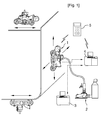
- a conventional surface attachment mobile robot 1 includes a vacuum generator 2 located on the ground so as to form a vacuum space for realizing attachment to the surface of a wall; an auxiliary controller 3 for controlling the vacuum generator 2; a main controller 4 for controlling the surface attachment mobile robot 1; and a wireless controller 5 capable of being attached/detached to/from the main controller 4, driving motors and the vacuum generator 2, and controlling the surface attachment mobile robot 1.
- the conventional surface attachment mobile robot 1 is a semi-autonomous mobile robot which always requires the wireless controller 5.
- the conventional surface attachment mobile robot 1 since the conventional surface attachment mobile robot 1 has a bidirectional wheel structure, it has a disadvantage in that it cannot freely travel on the inside surface of a cargo hold.
- US 5 809 099 A discloses an underwater robot, which is controlled by a laser pointer, wherein the robot moves such that the laser pointer arrives at the center of a position sensitive detector of the robot.
- EP 0 461 506 A1 discloses an underwater mobile type inspection system having a mobile vehicle device for travelling along internal wall surfaces in order to detect flaws.
- an object of the present invention is to provide a wall climbing robot using an indoor global positioning system, which can autonomously travel along the ceiling surface or vertical surfaces of the inside of a cargo hold or a tank using the IGPS signals of the indoor global positioning system.
- the wall climbing robot may include a navigation receiver configured to receive rotating fan beams emitted from one or more navigation transmitters of the indoor global positioning system, and recognize the rotating fan beams as IGPS signals; a robot frame to which the navigation receiver is mounted; a mobile controller configured to be installed on the robot frame, and to recognize and determine its own position using the IGPS signals; and a drive mechanism configured to travel along the surfaces of the room under control of the mobile controller.
- IGPS Indoor Global Positioning System
- the wall climbing robot further includes a marking module coupled to a mobile unit in which the mobile controller is installed, and configured to perform a marking operation.
- the wall climbing robot further includes a stud bolt welding module coupled to a mobile unit in which the mobile controller is installed, and configured to perform an operation of welding a stud bolt.
- a grinder module is further coupled to the mobile unit at an installation position where a preliminary grinding operation is performed with respect to the stud bolt welding module.
- the wall climbing robot further includes a depth measuring module coupled to a mobile unit in which the mobile controller is installed, and configured to perform a depth measurement operation.
- a plurality of first and second clamp units and a plurality of fastening elements are provided to a bottom of the drive mechanism so as to replace or simultaneously mount task modules.
- wall climbing robot using an indoor global positioning system includes a navigation receiver which recognizes rotating fan beams, emitted from navigation transmitters of the indoor global positioning system, as IGPS signals, it has an advantage in that it is possible for the robot to recognize and determine the current position thereof, and to autonomously travel or move to a target position.
- the wall climbing robot using an indoor global positioning system has an advantage in that it can more exactly and precisely perform traveling motion, compared to existing robots which depend only on encoder signals.
- the wall climbing robot using an indoor global positioning system includes a marking module, a stud bolt welding module, a grinder module, and a depth measuring module, or further includes an integrated module in which the respective modules are integrated, it has an advantage in that it can perform all of a marking operation, a welding operation, a preliminary grinding operation, and a depth measuring operation.
- FIG. 2 is a diagram showing the configuration of a system for a wall climbing robot using an indoor global positioning system according to an embodiment of the present invention
- FIG. 2 is a diagram showing the configuration of a system for a wall climbing robot using an indoor global positioning system according to an embodiment of the present invention.
- an indoor global positioning system 5 supplies information about an IGPS coordinate system for hull dimensions to a host system 200. Further, the indoor global positioning system 5 can transmit information about a current position to a mobile unit 100 or task modules 300, 400, 500, and 600.
- the task modules 300, 400, 500, and 600 which will be described in detail later, are a marking module 300, a stud bolt welding module 400, a grinder module 500, and a depth measuring module 600.
- the host system 200 receives the Computer-Aided Design (CAD) design data of a hull, cargo hold design data, or the CAD design data of a specific space, which are separately input from the outside, determines the target position of a robot based on the data, and transmits information about the determined target position of the robot to the mobile unit 100.
- CAD Computer-Aided Design
- the wall climbing robot using an indoor global positioning system applies the coordinate values of a current position, transmitted from the indoor global positioning system 5 in real time, to the information about the target position of the robot, which is digital map information transmitted from the host system 200, so that the wall climbing robot can travel to the target position.
- the size of a room 10 can be obtained by mounting well-known laser measurement devices and a laser receiver in corner portions of the room 10, and repeatedly measuring the lengths of the diagonals or edges of respective surfaces based on the corner portions.
- the coordinate values of the respective corner portions or reference positions are converted into global coordinate values or coordinate values of the IGPS coordinate system for the hull dimensions, thereby completing digital map information based on the actual measurement of the corresponding room 10.
- more accurately and precisely completed digital map information can be stored and used in the central host computer 210 using a method of installing a separate length measurement transmitter (not shown) for transmitting IGPS signals and a plurality of length measurement receivers (not shown) for receiving the IGPS signals so as to measure the size of the room 10 in the room 10, measuring the positions of respective vertexes of the inside of the room 10 using the length measurement receivers, three-dimensionally realizing the room 10 based on the measured positions of the respective vertexes, and measuring the size of the room 10 (using a trigonometrical function).
- the present invention relates to a wall climbing robot using an indoor global positioning system, which receives IGPS signals and autonomously travels.
- the present invention employs a plurality of navigation transmitters 20, such as the IGPS installed in the room 10.
- Each of the navigation transmitters 20 emits two rotating fan beams 22 and 24, and includes a variable magnet 28 capable of being attached/detached to/from one end of the housing of the navigation transmitter 20 such that the navigation transmitter 20 can be temporarily attached to the flat portion of a membrane, which is the surface of the room 10.
- the variable magnet 28 is configured such that the generation or offset of the magnetic action of the variable magnet 28 can be controlled by switching a lever.
- the navigation transmitter 20 be installed at the corresponding position in the room 10 using the variable magnet 28.
- the installation position of the navigation transmitter 20 is the same as the position indicated by the coordinate values input to the central host computer 210 in advance.
- the host system 200 can upgrade auxiliary data for the brain-mounted mobile unit 100, unlike the existing network type or remote control type.
- the host system 200 includes a central host computer 210 having digital map information in which the space inside the room 10 is three-dimensionally coordinated; and an attachment force generator 220 for supplying a surface attachment medium "b" which corresponds to vacuum force for a plurality of vacuum pads (not shown) or electromagnetic force for a plurality of magnetic wheels, for the traveling motion of the mobile unit 100 according to the method of the drive mechanism of the mobile unit 100, that is, a vacuum method or a magnetic method.
- the central host computer 210 includes a wired or wireless first communication unit 211 capable of communicating with the mobile unit 100.
- the CAD design data which is digital map information, is input to the central host computer 210 of the host system 200.
- the central host computer 210 transmits the CAD design data, which is at least di gital map information, to the mobile unit 100 using the first communication unit 211, and receives position change checking information from the mobile unit 100. That is, the central host computer 210 performs bi-directional communication with the mobile unit 100 by transmitting/receiving data information "a" and can update the mobile unit 100.
- the central host computer 210 is connected to the attachment force generator 220 through an attachment force generator controller (not shown) so as to control the power supplying circuit (not shown) or the aspirator (not shown) of the attachment force generator 220.
- a central host computer 210 are provided with an attachment force generator driver and application programs for controlling the attachment force generator controller in the form of software.
- the attachment force generator driver and the application program adjust the amount of supply of the surface attachment medium "b" such as electromagnetic force, so as to realize the traveling motion of the mobile unit 100, for example, the motion of driving the mobile unit 100 with the magnetic wheels thereof attached to a flat portion.
- the central host computer 210 can display the current motion or working state of a robot on the monitor screen of the central host computer 210 using position change checking information transmitted from the mobile unit 100.
- the position change checking information preferably includes position information values (coordinate values) recognized and determined based on at least the motion of the robot.
- the mobile unit 100 includes a second communication unit 110 capable of performing mutual identification and data communication with the first communication unit 211 of the host system 200.
- the first communication unit 211 and the second communication unit 110 support well-known wired or wireless data communication interfaces, thereby having compatible structures.
- the mobile unit 100 includes a supply connection unit 120 based on a technical standard corresponding to a specific connection pipe or connection line so as to receive the surface attachment medium "b" supplied from the attachment force generator 220.
- a supply connection unit 120 is not shown in detail in the drawing, the supply connection unit 120 is configured to supply the surface attachment medium "b" toward the vacuum pads or the magnetic wheels.
- FIG. 4 is a schematic diagram showing the configuration of the robot shown in FIG. 3 .
- the mobile unit 100 further includes a light-emitting alarm unit 130, an alerting alarm unit 140, a mobile controller 150, corresponding to the brains of the robot, a navigation receiver 160, a robot frame 170, and a drive mechanism 180.
- the light-emitting alarm unit 130 and the alerting alarm unit 140 are mounted around the second communication unit 110 or on the robot frame 170, and are connected to the mobile controller 150, which will be described later.
- the light-emitting alarm unit 130 and the alerting alarm unit 140 generate a fall alarm or a collision alarm in the form of light or sound when a situation in which the robot falls or collides with an obstacle is predicted by the mobile controller 150.
- the navigation receiver 160 is mounted or provided by being supported by the robot frame 170.
- the navigation receiver 160 receives IGPS signals from the above-described plurality of navigation transmitters, obtains the three-dimensional coordinates of a position corresponding to the time point of the reception, and periodically transmits the coordinates to the mobile controller 150.
- the method of recognizing (detecting) and determining the relative coordinate values (position) from the navigation transmitter 20, as described above, is used as the method of obtaining the three-dimensional coordinates of the navigation receiver 160.
- the robot frame 170 is a body or a chassis for supporting or installing all structures to be mounted on the mobile unit 100, and is formed of lightweight material, such as aluminum profile, but has strong durability.
- the drive mechanism 180 is provided below the robot frame 170.
- the drive mechanism 180 includes an attitude control sensor 191, a plurality of omnidirectional obstacle recognizing sensors 192, and a distance measuring sensor 193.
- the drive mechanism 180 further includes an external encoder for measuring total traveling speed, a load cell, and a potentiometer.
- the attitude control sensor 191 is used to control the travel or attitude using any of a well-known gyroscope, an accelerometer, a tilt sensor, an approach sensor, or a combination thereof.
- the omnidirectional obstacle recognizing sensors 192 are used to determine whether external objects or obstacles are coming close during the travel (motion).
- the distance measuring sensor 193 is used to measure the distance from an attachment surface (for example, a ceiling surface or a vertical surface), such as the surface of a cargo hold, and predict that the mobile unit 100 is falling.
- an attachment surface for example, a ceiling surface or a vertical surface
- the external encoder for measuring total traveling speed feeds back the total traveling speed of the robot to a central processing unit through a sensor signal processor.
- the load cell or the potentiometer is mounted on a steering system, and is used to detect the magnitude of attachment force and input the detected magnitude of the attachment force to the central processing unit through the sensor signal processor.
- a plurality of encoders (an external encoder and a motor encoder), including the attitude control sensor 191, the omnidirectional obstacle-recognizing sensors 192 and the distance measuring sensor 193, the load cell, and the potentiometer are used to detect operational state information for realizing the functions of controlling the attitude of a robot, providing an alert related to a fall, attributable to the deficiency of attachment (or vacuum) to a ceiling surface or a vertical surface, recognizing an obstacle, avoiding a collision with a obstacle, and providing an alert related to the collision with the obstacle.
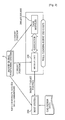
- the mobile controller 150 of FIG. 5 and the drive mechanism 180 of FIG. 6 will be described in detail below.
- the mobile controller 150 is provided in a robot, recognizes (determines) its own position using the IGPS signals, and enables the robot to autonomously travel to a target position.
- the mobile controller 150 includes a central processing unit 151, an input/output unit 152, a motion control unit 153, a drive control unit 154, a navigation control unit 155, a sensor signal processing unit 156, an emergency processing unit 157, an alarm generator 158, memory 159a, and a module connection unit 159b in an electronic circuit manner.
- these units will be divided according to the function and role thereof, and will then be described.
- the central processing unit 151 performs functions involved in the operation and control of all elements mounted on the robot according to the present invention.
- the central processing unit 151 uses a main board (for example, a Pulse-Code Modulation (PCM)-9577 board from Advantech Technologies, Inc.), which is small and supplies almost all computer control interfaces and is thus appropriate for robot engineering.
- the central processing unit 151 includes standard interfaces for a Video Graphics Array (VGA), a wired/wireless Local Area Network (LAN), a serial port, small-sized flash memory, a Universal Serial Bus (USB), a Hard Disk Drive (HDD), a Floppy Disk Drive (FDD), and the performance of various types of input/output, control, processing, and a generation function. Further, the central processing unit 151 is capable of being connected to a keyboard and a mouse.
- VGA Video Graphics Array
- LAN Local Area Network
- USB Universal Serial Bus
- HDD Hard Disk Drive
- FDD Floppy Disk Drive
- the input/output unit 152 includes a digital input/output module and an analog input/output module.
- the digital input/output module When the central processing unit 151 transmits digital signals to the outside, the digital input/output module has a function of receiving instructions from the central processing unit 151 and outputting the instructions to the outside through a PC104 bus. Further, when the central processing unit 151 receives digital signals from the outside, the digital input/output module has a function of receiving the digital signals from the outside and transmitting the digital signals to the central processing unit 151 through the PC104 bus.
- the analog input/output module has a function of receiving the instructions of the central processing unit 151 and outputting the instructions to the outside through the PC104 bus. Further, when the central processing unit 151 receives analog signals from the outside, the analog input/output module has a function of receiving the analog signals from the outside and transmitting the analog signals to the central processing unit 151 through the PC104 bus.
- the motion control unit 153 receives instructions, transmitted from the central processing unit 151 through the input/output unit 152, from an application program for performing the traveling motion of the wall climbing robot, analyzes and recognizes the instructions, and generates and outputs respective motor control signals for a first drive motor for steering the robot and a second drive motor for generating driving force.
- the motion control unit 153 occupies a small space and can prevent vibration using a PC104 bus structure, which is widely employed for an industrial central processing system.
- the instructions of the application program for performing the traveling motion of the wall climbing robot are transmitted to the main chip of the motion control unit 153, that is, a Field Programmable Gate Array (FPGA), which is one type of programmable logic chip, through the PC 104 bus.
- the FPGA transmits the motor control signals to the drive control unit 154.
- the motion control unit 153 receives motor encoder signals, fed back from the first and second drive motors, and recognizes the operational state of the first and second drive motors.
- the drive control unit 154 receives motor control signals output from the motion control unit 153, amplifies current, and generates motor output signals capable of actually driving the corresponding first and second drive motors of the drive mechanism, which will be described later.
- the motor output signals of the drive control unit 154 may be defined so as to be matched with any one of a motor control algorithm for a differential steering method used for conditions, such as off-road travel or high-speed travel, and a motor control algorithm for a holonomic control method of realizing omnidirectional drive.
- the navigation control unit 155 obtains coordinate values of the current position of the robot, as in a kind of localization, based on IGPS signals received by the navigation receiver 160 according to navigation execution commands input from the central processing unit 151, and recognizes and determines the current position of the robot by comparing the coordinate values with digital map information transmitted from the central host computer.
- the navigation control unit 155 plans paths for performing autonomous traveling or motion from the determined current position to a target position, or resets the paths so as to perform an operation of avoiding an obstacle.
- the sensor signal processing unit 156 can receive corresponding detection signals from the attitude control sensor 191, which corresponds to any one of a gyroscope, an accelerometer, a tilt sensor, and an proximity sensor, the omnidirectional obstacle-recognizing sensors 192, the distance measuring sensor 193, the external encoder for measuring total traveling speed, the motor encoder, the load cell, and the potentiometer.
- the sensor signal processing unit 156 converts the signals detected by the respective sensors into an internal digital signal form that the central processing unit 151 can recognize, and inputs the resulting signals to the central processing unit 151.
- the emergency processing unit 157 includes a specific artificial intelligent algorithm for recognizing obstacles or predicting that the robot will fall by comparing the detection signals of the respective sensors 191, 192, and 193 with preliminarily determined indexes and checking the comparison results in real time, in association with the central processing unit 151 and the sensor signal processing unit 156.
- the emergency processing unit 157 compares the detection signal of the attitude control sensor 191 with an attitude reference index, and checks the results of the comparison, and determines the attitude of the robot, thereby determining whether the robot is stable or unstable.
- the emergency processing unit 157 compares the detection signal of the omnidirectional obstacle recognizing sensors 192 with an obstacle reference index, and checks the results of the comparison, thereby determining whether external objects or obstacles are coming close during travel (motion).
- the emergency processing unit 157 compares a detection signal, detected by the distance measuring sensor 193, with a falling reference index, and checks the comparison result, thereby predicting that the robot will fall.
- Such determination results of the emergency processing unit 157 are transmitted to the alarm generator 158.
- the alarm generator 158 selectively applies or cuts off operational power in response to an alarm control signal (on/off signal) based on the determination results of the emergency processing unit 157, so that the light-emitting alarm unit or the alerting alarm unit generates a fall alarm or collision alarm using light or sound.
- the memory 159a is used to record and store the digital map information transmitted from the central host computer. Further, the memory 159a stores a predetermined operating system (for example, a Linux-based operating system), necessary for the overall operation of the robot according to the present invention, in a Random Access Memory (RAM) disk manner.
- a predetermined operating system for example, a Linux-based operating system
- RAM Random Access Memory
- the module connection unit 159b includes a well-known multichannel (Multiple Input Multiple Output (MIMO)) module connection interface for connecting the marking module, the stud bolt welding module, the grinder module, and the depth measuring module, which will be described later, to the mobile controller 150.
- MIMO Multiple Input Multiple Output
- the drive mechanism 180 includes omnidirectional wheels.
- the wheel structure of the drive mechanism 180 employed in the present invention is a tricycle, that is, the drive mechanism 180 includes first, second, and third drive wheel assemblies 181, 182, and 183.
- first, second, and third drive wheel assemblies 181, 182, and 183 a plurality of electromagnets is attached to the surface of a magnetic wheel 189, and the electromagnetic force is supplied to the electromagnets through rotational contact electrodes (not shown) for supplying power, so that attachment force can be generated on the flat portion of the membrane of the cargo hold by the electromagnetic force.
- the first drive wheel assembly 181 is provided for steering, and the remaining two drive wheel assemblies 182 and 183 may be manufactured to have a simple trailing wheel structure.
- the first drive wheel assembly 181 includes a first drive motor 184 for steering the robot and a second drive motor 185 for generating driving force.
- the pinion gear of the first drive motor 184 for steering is coupled to the rack gear of the circumference edge of the steering turntable 186.
- the first drive motor 184 rotates (steers) the steering turntable 186 and other objects combined therewith or related thereto in response to the motor output signal of the drive control unit.
- the housing of the second drive motor 185 is mounted on the steering turntable 186.
- the output rotating shaft of the deceleration gear of the second drive motor 185 rotatably passes through the steering turntable 186 toward a location below the steering turntable 186.
- a first intersecting shaft gear 187 coupled to the output rotating shaft of the second drive motor 185, is coupled to a second intersecting shaft gear 188 coupled to the first intersecting shaft gear 187.
- the shaft assembly of the second intersecting shaft gear 188 is combined to rotate the magnetic wheel 189 in the state of being supported by a suspension structure extending from the steering turntable 186.
- the second drive motor 185 generates turning force so as to provide the driving force of the magnetic wheel 189.
- the first drive motor 184 generates turning force so as to provide the steering of the first drive wheel assembly 181.
- second and third drive wheel assemblies 182 and 183 may be manufactured to realize steering and the generation of driving force in the same manner as the above-described first drive wheel assembly 181.
- each of motors is detected using an encoder corresponding to each of the plurality of drive motors (not shown) provided in the second and third drive wheel assemblies 182 and 183, in addition to the first and second drive motors 184 and 185 of the first drive wheel assembly 181, and omnidirectional control, which is generally performed to control a robot, is performed using a detected signal.
- the omnidirectional control may be implemented using a well-known method, and thus a description thereof will be omitted in the present invention.
- the above-described magnetic wheel 189 may be replaced by a vacuum wheel.
- FIG. 7 is a block diagram showing the marking module 300 to be coupled to the mobile unit 100 of the wall climbing robot using an indoor global positioning system according to the present invention.
- the marking module 300 shown in FIG. 7 is coupled to the first installation position of the mobile unit 100, which corresponds to any of the side and upper portions of the robot frame 170 and the bottom portion of the drive mechanism 180.
- the structure of supplying power between the rotation motor and the turntable which will be described later, may be a bevel gear structure, a worm and wormwheel gear structure, a pulley and belt structure, a direct rotational shaft-motor coupling structure, or a structure in which a motor is connected to a rotational shaft via a reduction gear in the present invention.
- the marking module 300 performs all marking operations, such as drawing lines or marking dots on the bottom, ceiling, and vertical surfaces of a cargo hold or tank.
- the marking module 300 includes a rotation motor 310 electrically connected to a marking controller (not shown) provided in the above-described mobile controller 150, and coupled to the installation position of the mobile unit 100 using a housing bracket; a turntable 320 coupled to receive the turning force of the rotation motor 310; a marking pen-carrying linear driver 330 provided below the turntable 320 and configured to generate moving force; a robot finger-type marking pen holder 340 configured to move by receiving the reciprocating feed force of the linear driver 330; a marking pen 350 mounted on the marking pen holder 340; and a marking pen changer 360 configured to detach/attach a plurality of marking pens 350 from/to the marking pen holder 340 based on the kind thereof.
- a marking controller not shown
- a well-known device such as a ball screw structure or a linear actuator, is used as means for generating moving force in the marking pen-carrying linear driver 330.
- the marking pen-carrying linear driver 330 has any one of liner, curved, circular, and rectangular arrangement structures based on the structural characteristics thereof.
- the marking pen-carrying linear driver 330 is connected to the marking controller (not shown) so as to mutually transmit control signals and feedback signals for checking the operation thereof.
- the marking controller is a well-known electronic circuit controller realized using a technique of planning and controlling paths formed by lines, circles, and dots, and is provided around the mobile controller 150.
- the marking pen-carrying linear driver 330 is connected to the mobile controller 150 through the marking controller and the module connection unit 159b illustrated in FIG. 5 , and is configured to associate the traveling motion with the marking operation of the robot.
- the marking controller is connected to a marking control driver provided in the operating system of the central processing unit of the mobile controller 150 using software, and is configured to perform a marking operation based on the instructions of an application program for a series of marking operations.
- FIG. 8 is a block diagram showing the stud bolt welding module 400 and the grinder module 500, which are coupled to the mobile unit 100 of the wall climbing robot using an indoor global positioning system according to the present invention.
- the stud bolt welding module 400 shown in FIG. 8 has the same construction as the well-known auto-carriage type welding device.
- the stud bolt welding module 400 is coupled to the second installation position of the mobile unit 100, which corresponds to any of the side and upper portions of the robot frame 170, the top portion of the mobile controller 150, and the bottom portion of the drive mechanism 180.
- the stud bolt welding module 400 may further include a multiple shaft mobile structure, which enables a swing operation, a tilt operation and an elevating operation using a plurality of ball screws and welding motors so as to realize multiple shaft motion, using a well-known method.
- the stud bolt welding module 400 includes a welding gun 430 on the end of the arm of the well-known multiple shaft mobile structure.
- the stud bolt welding module 400 further includes a welding/feeder controller (not shown) for performing motor control for rotating the ball screw thereof, operation control for welding, and stud bolt supply control.
- a welding/feeder controller (not shown) for performing motor control for rotating the ball screw thereof, operation control for welding, and stud bolt supply control.
- a welding/feeder control driver is further provided in the operating system of the central processing unit of the mobile controller 150 using software.
- the welding/feeder controller is physically connected to the mobile controller 150 through the module connection unit 159b shown in FIG. 5 , and is recognized in the mobile controller 150 through the welding/feeder control driver using software.
- the stud bolt welding module 400 can associate the welding operation with the grinder operation, which will be described later, while the mobile unit 100 performs the traveling motion.
- a stud bolt feeder 450 is provided in a portion which is placed beside the stud bolt welding module 400 and below the robot frame 170.
- the operation of the stud bolt feeder 450 is controlled by the above-described welding/feeder controller.
- the stud bolt feeder 450 is a kind of stud bolt supply device or loading device.
- the stud bolt feeder 450 separately supplies stud bolts toward the welding gun 430 such that the stud bolt welding module 400 welds the supplied stud bolts to the task position of a room (for example, a cargo hold).
- the stud bolt feeder 450 may include a bolt cartridge loaded with a plurality of stud bolts; a gripper feeding robot for carrying the stud bolts from the bolt cartridge to a task position; and a stud bolt loader provided on one end of the gripper feeding robot and formed so as not to obstruct the welding direction of the welding gun 430.
- the working position is determined based on data instructed (transmitted) by the central host computer.
- other methods of inputting a working position may include 1) a method of an operator directly inputting coordinate values; and 2) a method of a stud bolt attachment robot inputting coordinate values.
- An operator has a terminal for performing a coordinate input operation, which has the same technical spirit as the above-described navigation receiver and has personal Digital Assistant (PDA) functions capable of communicating with the central host computer.
- PDA personal Digital Assistant
- the operator manually attaches a stud bolt to the predetermined position of a cargo hold. Thereafter, the operator places the terminal for performing a coordinate input operation above the stud bolt.
- a coordinate input button is pressed through a Graphic User Interface (GUI) realized in the terminal
- the IGPS signals of the navigation receiver is received, so that the coordinate values of the position where the stud bolt is attached are automatically transmitted to the central host computer.
- the coordinate values of the position where the stud bolt is attached are the target position of the above-described robot according to the present invention.
- the above-described mobile unit 100 moves from its current position to the position where the stud bolt is attached, that is, the target position. Thereafter, the stud bolt welding module 400 provided in the mobile unit 100 performs welding on the contact between the stud bolt and the cargo hold.
- the stud bolt attachment robot is loaded with a plurality of stud bolts in the form of a cartridge, and can autonomously move inside the cargo hold using a wheel structure which is the same as that of the above-described mobile unit.
- Each of the stud bolts loaded in the form of a cartridge in the stud bolt attachment robot is provided with adhesive tape on the head thereof in advance so as to be separately attached on the cargo hold.
- the stud bolt attachment robot Whenever the stud bolt attachment robot separately attaches the stud bolts on the cargo hold, the stud bolt attachment robot recognizes and determines coordinate values corresponding to the attachment position using the IGPS signals of the above-described navigation receiver, and transmits the determined coordinate values to the central host computer.
- the mobile unit 100 moves from its current position to the position where the stud bolt in present, that is, the target position, and the stud bolt welding module 400, mounted on the mobile unit 100, performs welding.
- the grinder module 500 is coupled around the stud bolt welding module 400 or is coupled to the third installation position, which is loaded before the stud bolt welding module 400.
- the grinder module 500 is a module for performing a preliminary grinding operation with respect to a stud bolt welding position.
- the grinder module 500 may be used to remove the weld beads of a weld line formed by the stud bolt welding module 400.
- the grinder module 500 is connected to the mobile controller 150 through the grinder controller (not shown) and a module connection unit in the same way as the above-described marking module or the stud bolt welding module 400.
- the grinder module 500 generates turning force for performing preliminary grinding with respect to the stud bolt welding module 400, and is electrically connected to the mobile controller 150 so as to perform automation works using the mobile controller 150 according to the present invention or using general robot control technology, thereby receiving power for a grinding motor of the grinder module 500 and operating.
- FIG. 9 is a block diagram showing the depth measuring module 600 which is coupled to the multifunctional wall climbing robot according to the present invention using the indoor global positioning system.
- the depth measuring module 600 is coupled to the fourth installation position of the mobile unit 100, which corresponds to any of the side and upper portions of the robot frame 170 and the bottom portion of the drive mechanism 180.
- the depth measuring module 600 includes a measurement unit 610 configured to support any distance measurement method selected from among a stroke motion method, a laser method, and an ultrasonic method, in the same way as the above-described marking module, stud bolt welding module, and grinder module; and a depth measurement controller 620 mounted in the measurement unit 610 and configured to perform the operation of measuring depth.
- the depth measurement controller 620 is connected to the mobile controller 150 through the module connection unit.
- the depth measuring module 600 also performs automation works using the mobile controller 150 according to the present invention or according to general robot control technology. That is, the depth measurement controller of the depth measuring module 600 is connected to a depth measurement control driver provided in the operating system of the central processing unit of the mobile controller 150 using software, and is configured to perform the depth measurement operation based on the instructions of an application program for a series of depth measurement operations while the robot is traveling or stopped.
- the depth measurement operation is the operation in which the depth measuring module 600 determines a reference point of a flat portion and measures relative depth based on the reference point.
- a plurality of first clamp units 701, a plurality of second clamp units 702, and a plurality of fastening elements 703 are provided to the bottom of the drive mechanism 180 of a separate type mobile unit 100a so as to replace or mount the task modules 300, 400, 500, and 600.
- each of the first clamp units 701 is configured to have the shape of a coupling plate, and is coupled to each of the installation surfaces of the task modules 300, 400, 500, and 600.
- Each of the second clamp units 702 is configured to have a shape capable of fastening the first clamp unit 701, and is fastened to the bottom of the drive mechanism 180.
- Each of the fastening elements 703 is configured to have the shape of well-known locking/unlocking equipment, and is coupled to the side of the first and second clamp units 701 and 702 so as to attach/detach the first and second clamp units 701 and 702.
- the separate type mobile unit 100a has an advantage in that the task modules 300, 400, 500, and 600 can be individually selected if necessary.
- a combination type mobile unit 100b which has a different type of layout, includes a plurality of first clamp units 701, a plurality of second clamp units 702b, and a plurality of fastening elements 703 on the bottom of a drive mechanism 180b so as to simultaneously mount the task modules 300, 400, 500, and 600, so that there is an advantage in that multitasking is possible.
Landscapes
- Engineering & Computer Science (AREA)
- Physics & Mathematics (AREA)
- Radar, Positioning & Navigation (AREA)
- Remote Sensing (AREA)
- General Physics & Mathematics (AREA)
- Aviation & Aerospace Engineering (AREA)
- Automation & Control Theory (AREA)
- Electromagnetism (AREA)
- Optics & Photonics (AREA)
- Computer Networks & Wireless Communication (AREA)
- Mechanical Engineering (AREA)
- Chemical & Material Sciences (AREA)
- Combustion & Propulsion (AREA)
- Transportation (AREA)
- Robotics (AREA)
- Control Of Position, Course, Altitude, Or Attitude Of Moving Bodies (AREA)
- Manipulator (AREA)
Description
- The present invention relates to a wall climbing robot that uses an indoor global positioning system.
- Generally, a Global Positioning System (GPS) is a device for recognizing and determining three-dimensional coordinate values (hereinafter referred to as "coordinate values") corresponding to the position of a GPS receiver using three or more GPS satellites.
- This concept is applied to an Indoor Global Positioning System (IGPS).
U.S. Patent No. 6,501,543 discloses information using this concept. -
U.S. Patent No. 6,501,543 discloses transmitters corresponding to the above-described GPS satellites, and a receiver corresponding to the GPS receiver. - Each of the transmitters emits two rotating fan beams. The rotating fan beams may be laser fan beams or another type of light emission medium.
- The receiver receives rotating fan beams emitted from the transmitters, and determines positions relative to the transmitters. Here, since the rotating fan beams cross each other at predetermined angles, the coordinate values of the receiver for receiving the rotating fan beams, that is, the position or altitude thereof, can be measured.
- Meanwhile, the basic concept of existing autonomous mobile robots is to travel on flat surfaces, that is, horizontal flat surfaces, using self-generated information or real-time positioning information transmitted through communication
- In particular, one core element of such conventional autonomous mobile robots is a drive mechanism, and the drive mechanism includes chain, wheel, and multilegged-type drive mechanisms.
- Meanwhile, spider robots or attachment robots are robots which overcome the limitations of the flat-surface mobile robots and travel on ceilings or vertical surfaces.
- The conventional ceiling-surface/vertical-surface mobile robots cannot travel autonomously, as compared with general flat-surface mobile robot, and are semi-autonomous mobile robots which must ride on fixed rails or be remotely controlled by a person.
- In particular, such equipment using rails has limitations on the traveling range or operational area, and cannot be used in practice in an unsuitable installation space or a place where frames, such as rails, cannot be easily attached.
- For example, as shown in
FIG. 1 , a conventional surface attachment mobile robot 1 includes avacuum generator 2 located on the ground so as to form a vacuum space for realizing attachment to the surface of a wall; anauxiliary controller 3 for controlling thevacuum generator 2; a main controller 4 for controlling the surface attachment mobile robot 1; and awireless controller 5 capable of being attached/detached to/from the main controller 4, driving motors and thevacuum generator 2, and controlling the surface attachment mobile robot 1. The conventional surface attachment mobile robot 1 is a semi-autonomous mobile robot which always requires thewireless controller 5. - Further, since the conventional surface attachment mobile robot 1 has a bidirectional wheel structure, it has a disadvantage in that it cannot freely travel on the inside surface of a cargo hold.
- Furthermore, there are no ceiling surface/vertical surface-dedicated autonomous mobile robots which recognize their own positions and reach destinations.
-
US 5 809 099 A discloses an underwater robot, which is controlled by a laser pointer, wherein the robot moves such that the laser pointer arrives at the center of a position sensitive detector of the robot. -
EP 0 461 506 A1 discloses an underwater mobile type inspection system having a mobile vehicle device for travelling along internal wall surfaces in order to detect flaws. - Accordingly, the present invention has been made keeping in mind the above problems occurring in the prior art, and an object of the present invention is to provide a wall climbing robot using an indoor global positioning system, which can autonomously travel along the ceiling surface or vertical surfaces of the inside of a cargo hold or a tank using the IGPS signals of the indoor global positioning system.
- In order to accomplish the above object, the present invention provides a wall climbing robot using an Indoor Global Positioning System (IGPS) provided in a room according to claim 1. Preferred embodiments of the present invention are described in the dependent claims. The wall climbing robot may include a navigation receiver configured to receive rotating fan beams emitted from one or more navigation transmitters of the indoor global positioning system, and recognize the rotating fan beams as IGPS signals; a robot frame to which the navigation receiver is mounted; a mobile controller configured to be installed on the robot frame, and to recognize and determine its own position using the IGPS signals; and a drive mechanism configured to travel along the surfaces of the room under control of the mobile controller.
- According to the present invention, the wall climbing robot further includes a marking module coupled to a mobile unit in which the mobile controller is installed, and configured to perform a marking operation.
- According to the present invention, the wall climbing robot further includes a stud bolt welding module coupled to a mobile unit in which the mobile controller is installed, and configured to perform an operation of welding a stud bolt.
- According to the present invention, a grinder module is further coupled to the mobile unit at an installation position where a preliminary grinding operation is performed with respect to the stud bolt welding module.
- According to the present invention, the wall climbing robot further includes a depth measuring module coupled to a mobile unit in which the mobile controller is installed, and configured to perform a depth measurement operation.
- According to the present invention, a plurality of first and second clamp units and a plurality of fastening elements are provided to a bottom of the drive mechanism so as to replace or simultaneously mount task modules.
- wall climbing robot using an indoor global positioning system according to the present invention includes a navigation receiver which recognizes rotating fan beams, emitted from navigation transmitters of the indoor global positioning system, as IGPS signals, it has an advantage in that it is possible for the robot to recognize and determine the current position thereof, and to autonomously travel or move to a target position.
- Further, the wall climbing robot using an indoor global positioning system according to the present invention has an advantage in that it can more exactly and precisely perform traveling motion, compared to existing robots which depend only on encoder signals.
- Furthermore, since the wall climbing robot using an indoor global positioning system according to the present invention includes a marking module, a stud bolt welding module, a grinder module, and a depth measuring module, or further includes an integrated module in which the respective modules are integrated, it has an advantage in that it can perform all of a marking operation, a welding operation, a preliminary grinding operation, and a depth measuring operation.
- surface attachment mobile robot;
FIG. 2 is a diagram showing the configuration of a system for a wall climbing robot using an indoor global positioning system according to an embodiment of the present invention; -
FIG. 3 is a view showing the working state of the robot shown inFIG. 2 ; -
FIG. 4 is a block diagram showing the configuration of the robot shown inFIG. 3 ; -
FIG. 5 is a block diagram showing the mobile controller shown inFIG. 4 ; -
FIG. 6 is a block diagram having an enlarged cross-sectional view for showing the drive mechanism shown inFIG. 4 ; -
FIG. 7 is a block diagram showing a marking module coupled to the wall climbing robot using an indoor global positioning system according to the present invention; -
FIG. 8 is a block diagram showing a stud bolt welding module and a grinder module coupled to the wall climbing robot using an indoor global positioning system according to the present invention; -
FIG. 9 is a block diagram showing a depth measuring module coupled to the wall climbing robot using an indoor global positioning system according to the present invention; -
FIG. 10 is a view showing an example of the application of the wall climbing robot using an indoor global positioning system according to the present invention; and -
FIG. 11 is a view showing another example of the application of the wall climbing robot using an indoor global positioning system according to the present invention. - The present invention will be described in detail with reference to the attached drawings below through descriptions of preferred embodiments. The same reference numerals used throughout the different drawings designate the same components.
-
FIG. 2 is a diagram showing the configuration of a system for a wall climbing robot using an indoor global positioning system according to an embodiment of the present invention. - As shown in
FIG. 2 , with regard to the input/output of the system for the robot according to the present invention, an indoorglobal positioning system 5 supplies information about an IGPS coordinate system for hull dimensions to ahost system 200. Further, the indoorglobal positioning system 5 can transmit information about a current position to amobile unit 100 ortask modules - The
task modules module 300, a studbolt welding module 400, agrinder module 500, and a depth measuringmodule 600. - The
host system 200 receives the Computer-Aided Design (CAD) design data of a hull, cargo hold design data, or the CAD design data of a specific space, which are separately input from the outside, determines the target position of a robot based on the data, and transmits information about the determined target position of the robot to themobile unit 100. - The wall climbing robot using an indoor global positioning system according to the present invention applies the coordinate values of a current position, transmitted from the indoor
global positioning system 5 in real time, to the information about the target position of the robot, which is digital map information transmitted from thehost system 200, so that the wall climbing robot can travel to the target position. - Referring to a diagram showing the working state of a robot illustrated in
FIG. 3 , the size of aroom 10 can be obtained by mounting well-known laser measurement devices and a laser receiver in corner portions of theroom 10, and repeatedly measuring the lengths of the diagonals or edges of respective surfaces based on the corner portions. - Thereafter, the coordinate values of the respective corner portions or reference positions are converted into global coordinate values or coordinate values of the IGPS coordinate system for the hull dimensions, thereby completing digital map information based on the actual measurement of the
corresponding room 10. - The digital map information completed as described above or the CAD design data about the
room 10, which is separately input from the outside, are recorded, stored, and managed by acentral host computer 210, are transmitted to the wall climbing robot using an indoor global positioning system according to the present invention, which will be described later, via a wired or wireless communication method, and are used for the navigation of the robot. - Meanwhile, according to the present invention, more accurately and precisely completed digital map information can be stored and used in the
central host computer 210 using a method of installing a separate length measurement transmitter (not shown) for transmitting IGPS signals and a plurality of length measurement receivers (not shown) for receiving the IGPS signals so as to measure the size of theroom 10 in theroom 10, measuring the positions of respective vertexes of the inside of theroom 10 using the length measurement receivers, three-dimensionally realizing theroom 10 based on the measured positions of the respective vertexes, and measuring the size of the room 10 (using a trigonometrical function). - The present invention relates to a wall climbing robot using an indoor global positioning system, which receives IGPS signals and autonomously travels.
- For this purpose, the present invention employs a plurality of
navigation transmitters 20, such as the IGPS installed in theroom 10. - Each of the
navigation transmitters 20 emits two rotating fan beams 22 and 24, and includes avariable magnet 28 capable of being attached/detached to/from one end of the housing of thenavigation transmitter 20 such that thenavigation transmitter 20 can be temporarily attached to the flat portion of a membrane, which is the surface of theroom 10. Thevariable magnet 28 is configured such that the generation or offset of the magnetic action of thevariable magnet 28 can be controlled by switching a lever. - It is preferable that the
navigation transmitter 20 be installed at the corresponding position in theroom 10 using thevariable magnet 28. - Here, the installation position of the
navigation transmitter 20 is the same as the position indicated by the coordinate values input to thecentral host computer 210 in advance. - The
host system 200 according to the present invention can upgrade auxiliary data for the brain-mountedmobile unit 100, unlike the existing network type or remote control type. - The
host system 200 includes acentral host computer 210 having digital map information in which the space inside theroom 10 is three-dimensionally coordinated; and anattachment force generator 220 for supplying a surface attachment medium "b" which corresponds to vacuum force for a plurality of vacuum pads (not shown) or electromagnetic force for a plurality of magnetic wheels, for the traveling motion of themobile unit 100 according to the method of the drive mechanism of themobile unit 100, that is, a vacuum method or a magnetic method. - The
central host computer 210 includes a wired or wirelessfirst communication unit 211 capable of communicating with themobile unit 100. - First, the CAD design data, which is digital map information, is input to the
central host computer 210 of thehost system 200. - The
central host computer 210 transmits the CAD design data, which is at least di gital map information, to themobile unit 100 using thefirst communication unit 211, and receives position change checking information from themobile unit 100. That is, thecentral host computer 210 performs bi-directional communication with themobile unit 100 by transmitting/receiving data information "a" and can update themobile unit 100. - Further, the
central host computer 210 is connected to theattachment force generator 220 through an attachment force generator controller (not shown) so as to control the power supplying circuit (not shown) or the aspirator (not shown) of theattachment force generator 220. - In such a
central host computer 210 are provided with an attachment force generator driver and application programs for controlling the attachment force generator controller in the form of software. - Here, the attachment force generator driver and the application program adjust the amount of supply of the surface attachment medium "b" such as electromagnetic force, so as to realize the traveling motion of the
mobile unit 100, for example, the motion of driving themobile unit 100 with the magnetic wheels thereof attached to a flat portion. - Further, the
central host computer 210 can display the current motion or working state of a robot on the monitor screen of thecentral host computer 210 using position change checking information transmitted from themobile unit 100. - For this purpose, the position change checking information preferably includes position information values (coordinate values) recognized and determined based on at least the motion of the robot.
- Meanwhile, the
mobile unit 100 includes asecond communication unit 110 capable of performing mutual identification and data communication with thefirst communication unit 211 of thehost system 200. Thefirst communication unit 211 and thesecond communication unit 110 support well-known wired or wireless data communication interfaces, thereby having compatible structures. - The
mobile unit 100 includes asupply connection unit 120 based on a technical standard corresponding to a specific connection pipe or connection line so as to receive the surface attachment medium "b" supplied from theattachment force generator 220. Here, although thesupply connection unit 120 is not shown in detail in the drawing, thesupply connection unit 120 is configured to supply the surface attachment medium "b" toward the vacuum pads or the magnetic wheels. -
FIG. 4 is a schematic diagram showing the configuration of the robot shown inFIG. 3 . - As shown in
FIG. 4 , besides the above-describedsecond communication unit 110 andsupply connection unit 120, themobile unit 100 further includes a light-emittingalarm unit 130, an alertingalarm unit 140, amobile controller 150, corresponding to the brains of the robot, anavigation receiver 160, arobot frame 170, and adrive mechanism 180. - The light-emitting
alarm unit 130 and the alertingalarm unit 140 are mounted around thesecond communication unit 110 or on therobot frame 170, and are connected to themobile controller 150, which will be described later. - The light-emitting
alarm unit 130 and the alertingalarm unit 140 generate a fall alarm or a collision alarm in the form of light or sound when a situation in which the robot falls or collides with an obstacle is predicted by themobile controller 150. - The
navigation receiver 160 is mounted or provided by being supported by therobot frame 170. Thenavigation receiver 160 receives IGPS signals from the above-described plurality of navigation transmitters, obtains the three-dimensional coordinates of a position corresponding to the time point of the reception, and periodically transmits the coordinates to themobile controller 150. Here, the method of recognizing (detecting) and determining the relative coordinate values (position) from thenavigation transmitter 20, as described above, is used as the method of obtaining the three-dimensional coordinates of thenavigation receiver 160. - The
robot frame 170 is a body or a chassis for supporting or installing all structures to be mounted on themobile unit 100, and is formed of lightweight material, such as aluminum profile, but has strong durability. - The
drive mechanism 180 is provided below therobot frame 170. Thedrive mechanism 180 includes anattitude control sensor 191, a plurality of omnidirectionalobstacle recognizing sensors 192, and adistance measuring sensor 193. Preferably, thedrive mechanism 180 further includes an external encoder for measuring total traveling speed, a load cell, and a potentiometer. - Here, the
attitude control sensor 191 is used to control the travel or attitude using any of a well-known gyroscope, an accelerometer, a tilt sensor, an approach sensor, or a combination thereof. - The omnidirectional
obstacle recognizing sensors 192 are used to determine whether external objects or obstacles are coming close during the travel (motion). - The
distance measuring sensor 193 is used to measure the distance from an attachment surface (for example, a ceiling surface or a vertical surface), such as the surface of a cargo hold, and predict that themobile unit 100 is falling. - The external encoder for measuring total traveling speed feeds back the total traveling speed of the robot to a central processing unit through a sensor signal processor.
- The load cell or the potentiometer is mounted on a steering system, and is used to detect the magnitude of attachment force and input the detected magnitude of the attachment force to the central processing unit through the sensor signal processor.
- A plurality of encoders (an external encoder and a motor encoder), including the
attitude control sensor 191, the omnidirectional obstacle-recognizingsensors 192 and thedistance measuring sensor 193, the load cell, and the potentiometer are used to detect operational state information for realizing the functions of controlling the attitude of a robot, providing an alert related to a fall, attributable to the deficiency of attachment (or vacuum) to a ceiling surface or a vertical surface, recognizing an obstacle, avoiding a collision with a obstacle, and providing an alert related to the collision with the obstacle. - The
mobile controller 150 ofFIG. 5 and thedrive mechanism 180 ofFIG. 6 will be described in detail below. - The
mobile controller 150 is provided in a robot, recognizes (determines) its own position using the IGPS signals, and enables the robot to autonomously travel to a target position. - As shown in
FIG. 5 , themobile controller 150 includes acentral processing unit 151, an input/output unit 152, amotion control unit 153, adrive control unit 154, anavigation control unit 155, a sensorsignal processing unit 156, anemergency processing unit 157, analarm generator 158,memory 159a, and amodule connection unit 159b in an electronic circuit manner. In this embodiment, these units will be divided according to the function and role thereof, and will then be described. - The
central processing unit 151 performs functions involved in the operation and control of all elements mounted on the robot according to the present invention. Thecentral processing unit 151 uses a main board (for example, a Pulse-Code Modulation (PCM)-9577 board from Advantech Technologies, Inc.), which is small and supplies almost all computer control interfaces and is thus appropriate for robot engineering. Thecentral processing unit 151 includes standard interfaces for a Video Graphics Array (VGA), a wired/wireless Local Area Network (LAN), a serial port, small-sized flash memory, a Universal Serial Bus (USB), a Hard Disk Drive (HDD), a Floppy Disk Drive (FDD), and the performance of various types of input/output, control, processing, and a generation function. Further, thecentral processing unit 151 is capable of being connected to a keyboard and a mouse. - The input/
output unit 152 includes a digital input/output module and an analog input/output module. - When the
central processing unit 151 transmits digital signals to the outside, the digital input/output module has a function of receiving instructions from thecentral processing unit 151 and outputting the instructions to the outside through a PC104 bus. Further, when thecentral processing unit 151 receives digital signals from the outside, the digital input/output module has a function of receiving the digital signals from the outside and transmitting the digital signals to thecentral processing unit 151 through the PC104 bus. - In the same way, when the
central processing unit 151 transmits analog signals to the outside, the analog input/output module has a function of receiving the instructions of thecentral processing unit 151 and outputting the instructions to the outside through the PC104 bus. Further, when thecentral processing unit 151 receives analog signals from the outside, the analog input/output module has a function of receiving the analog signals from the outside and transmitting the analog signals to thecentral processing unit 151 through the PC104 bus. - The
motion control unit 153 receives instructions, transmitted from thecentral processing unit 151 through the input/output unit 152, from an application program for performing the traveling motion of the wall climbing robot, analyzes and recognizes the instructions, and generates and outputs respective motor control signals for a first drive motor for steering the robot and a second drive motor for generating driving force. Themotion control unit 153 occupies a small space and can prevent vibration using a PC104 bus structure, which is widely employed for an industrial central processing system. - Here, the instructions of the application program for performing the traveling motion of the wall climbing robot are transmitted to the main chip of the
motion control unit 153, that is, a Field Programmable Gate Array (FPGA), which is one type of programmable logic chip, through the PC 104 bus. The FPGA transmits the motor control signals to thedrive control unit 154. Further, themotion control unit 153 receives motor encoder signals, fed back from the first and second drive motors, and recognizes the operational state of the first and second drive motors. - The
drive control unit 154 receives motor control signals output from themotion control unit 153, amplifies current, and generates motor output signals capable of actually driving the corresponding first and second drive motors of the drive mechanism, which will be described later. - The motor output signals of the
drive control unit 154 may be defined so as to be matched with any one of a motor control algorithm for a differential steering method used for conditions, such as off-road travel or high-speed travel, and a motor control algorithm for a holonomic control method of realizing omnidirectional drive. - The
navigation control unit 155 obtains coordinate values of the current position of the robot, as in a kind of localization, based on IGPS signals received by thenavigation receiver 160 according to navigation execution commands input from thecentral processing unit 151, and recognizes and determines the current position of the robot by comparing the coordinate values with digital map information transmitted from the central host computer. - The
navigation control unit 155 plans paths for performing autonomous traveling or motion from the determined current position to a target position, or resets the paths so as to perform an operation of avoiding an obstacle. - The sensor
signal processing unit 156 can receive corresponding detection signals from theattitude control sensor 191, which corresponds to any one of a gyroscope, an accelerometer, a tilt sensor, and an proximity sensor, the omnidirectional obstacle-recognizingsensors 192, thedistance measuring sensor 193, the external encoder for measuring total traveling speed, the motor encoder, the load cell, and the potentiometer. - The sensor
signal processing unit 156 converts the signals detected by the respective sensors into an internal digital signal form that thecentral processing unit 151 can recognize, and inputs the resulting signals to thecentral processing unit 151. - The
emergency processing unit 157 includes a specific artificial intelligent algorithm for recognizing obstacles or predicting that the robot will fall by comparing the detection signals of therespective sensors central processing unit 151 and the sensorsignal processing unit 156. - That is, the
emergency processing unit 157 compares the detection signal of theattitude control sensor 191 with an attitude reference index, and checks the results of the comparison, and determines the attitude of the robot, thereby determining whether the robot is stable or unstable. - Further, the
emergency processing unit 157 compares the detection signal of the omnidirectionalobstacle recognizing sensors 192 with an obstacle reference index, and checks the results of the comparison, thereby determining whether external objects or obstacles are coming close during travel (motion). - Furthermore, the
emergency processing unit 157 compares a detection signal, detected by thedistance measuring sensor 193, with a falling reference index, and checks the comparison result, thereby predicting that the robot will fall. - Such determination results of the
emergency processing unit 157 are transmitted to thealarm generator 158. - The
alarm generator 158 selectively applies or cuts off operational power in response to an alarm control signal (on/off signal) based on the determination results of theemergency processing unit 157, so that the light-emitting alarm unit or the alerting alarm unit generates a fall alarm or collision alarm using light or sound. - The
memory 159a is used to record and store the digital map information transmitted from the central host computer. Further, thememory 159a stores a predetermined operating system (for example, a Linux-based operating system), necessary for the overall operation of the robot according to the present invention, in a Random Access Memory (RAM) disk manner. - The
module connection unit 159b includes a well-known multichannel (Multiple Input Multiple Output (MIMO)) module connection interface for connecting the marking module, the stud bolt welding module, the grinder module, and the depth measuring module, which will be described later, to themobile controller 150. - As shown in
FIG. 6 , thedrive mechanism 180 includes omnidirectional wheels. - For example, the wheel structure of the
drive mechanism 180 employed in the present invention is a tricycle, that is, thedrive mechanism 180 includes first, second, and thirddrive wheel assemblies - In the first, second, and third
drive wheel assemblies magnetic wheel 189, and the electromagnetic force is supplied to the electromagnets through rotational contact electrodes (not shown) for supplying power, so that attachment force can be generated on the flat portion of the membrane of the cargo hold by the electromagnetic force. - Here, the first
drive wheel assembly 181 is provided for steering, and the remaining twodrive wheel assemblies - For example, the first
drive wheel assembly 181 includes afirst drive motor 184 for steering the robot and asecond drive motor 185 for generating driving force. - The pinion gear of the
first drive motor 184 for steering is coupled to the rack gear of the circumference edge of thesteering turntable 186. Thefirst drive motor 184 rotates (steers) thesteering turntable 186 and other objects combined therewith or related thereto in response to the motor output signal of the drive control unit. - Here, the housing of the
second drive motor 185 is mounted on thesteering turntable 186. The output rotating shaft of the deceleration gear of thesecond drive motor 185 rotatably passes through thesteering turntable 186 toward a location below the steeringturntable 186. - Below the
steering turntable 186, a firstintersecting shaft gear 187, coupled to the output rotating shaft of thesecond drive motor 185, is coupled to a secondintersecting shaft gear 188 coupled to the firstintersecting shaft gear 187. - The shaft assembly of the second
intersecting shaft gear 188 is combined to rotate themagnetic wheel 189 in the state of being supported by a suspension structure extending from the steeringturntable 186. - The
second drive motor 185 generates turning force so as to provide the driving force of themagnetic wheel 189. Thefirst drive motor 184 generates turning force so as to provide the steering of the firstdrive wheel assembly 181. - Further, the second and third
drive wheel assemblies drive wheel assembly 181. - In this case, the operational state of each of motors is detected using an encoder corresponding to each of the plurality of drive motors (not shown) provided in the second and third
drive wheel assemblies second drive motors drive wheel assembly 181, and omnidirectional control, which is generally performed to control a robot, is performed using a detected signal. The omnidirectional control may be implemented using a well-known method, and thus a description thereof will be omitted in the present invention. - Further, according to the present invention, the above-described
magnetic wheel 189 may be replaced by a vacuum wheel. -
FIG. 7 is a block diagram showing the markingmodule 300 to be coupled to themobile unit 100 of the wall climbing robot using an indoor global positioning system according to the present invention. - The marking
module 300 shown inFIG. 7 is coupled to the first installation position of themobile unit 100, which corresponds to any of the side and upper portions of therobot frame 170 and the bottom portion of thedrive mechanism 180. - As the installation position of the
mobile unit 100 selectively changes, the structure of supplying power between the rotation motor and the turntable, which will be described later, may be a bevel gear structure, a worm and wormwheel gear structure, a pulley and belt structure, a direct rotational shaft-motor coupling structure, or a structure in which a motor is connected to a rotational shaft via a reduction gear in the present invention. - The marking
module 300 performs all marking operations, such as drawing lines or marking dots on the bottom, ceiling, and vertical surfaces of a cargo hold or tank. - For this purpose, the marking
module 300 includes a rotation motor 310 electrically connected to a marking controller (not shown) provided in the above-describedmobile controller 150, and coupled to the installation position of themobile unit 100 using a housing bracket; aturntable 320 coupled to receive the turning force of the rotation motor 310; a marking pen-carryinglinear driver 330 provided below theturntable 320 and configured to generate moving force; a robot finger-type markingpen holder 340 configured to move by receiving the reciprocating feed force of thelinear driver 330; a markingpen 350 mounted on the markingpen holder 340; and a markingpen changer 360 configured to detach/attach a plurality of markingpens 350 from/to the markingpen holder 340 based on the kind thereof. - Here, a well-known device, such as a ball screw structure or a linear actuator, is used as means for generating moving force in the marking pen-carrying
linear driver 330. - Further, the marking pen-carrying
linear driver 330 has any one of liner, curved, circular, and rectangular arrangement structures based on the structural characteristics thereof. - The marking pen-carrying
linear driver 330 is connected to the marking controller (not shown) so as to mutually transmit control signals and feedback signals for checking the operation thereof. - The marking controller is a well-known electronic circuit controller realized using a technique of planning and controlling paths formed by lines, circles, and dots, and is provided around the
mobile controller 150. - The marking pen-carrying
linear driver 330 is connected to themobile controller 150 through the marking controller and themodule connection unit 159b illustrated inFIG. 5 , and is configured to associate the traveling motion with the marking operation of the robot. - Further, the marking controller is connected to a marking control driver provided in the operating system of the central processing unit of the
mobile controller 150 using software, and is configured to perform a marking operation based on the instructions of an application program for a series of marking operations. -
FIG. 8 is a block diagram showing the studbolt welding module 400 and thegrinder module 500, which are coupled to themobile unit 100 of the wall climbing robot using an indoor global positioning system according to the present invention. - The stud
bolt welding module 400 shown inFIG. 8 has the same construction as the well-known auto-carriage type welding device. - That is, the stud
bolt welding module 400 is coupled to the second installation position of themobile unit 100, which corresponds to any of the side and upper portions of therobot frame 170, the top portion of themobile controller 150, and the bottom portion of thedrive mechanism 180. Further, as in a general multiple shaft linear robot, the studbolt welding module 400 may further include a multiple shaft mobile structure, which enables a swing operation, a tilt operation and an elevating operation using a plurality of ball screws and welding motors so as to realize multiple shaft motion, using a well-known method. - The stud
bolt welding module 400 includes awelding gun 430 on the end of the arm of the well-known multiple shaft mobile structure. - The stud
bolt welding module 400 further includes a welding/feeder controller (not shown) for performing motor control for rotating the ball screw thereof, operation control for welding, and stud bolt supply control. - A welding/feeder control driver is further provided in the operating system of the central processing unit of the
mobile controller 150 using software. - Therefore, the welding/feeder controller is physically connected to the
mobile controller 150 through themodule connection unit 159b shown inFIG. 5 , and is recognized in themobile controller 150 through the welding/feeder control driver using software. According to such a connection and reorganization relationship, the studbolt welding module 400 can associate the welding operation with the grinder operation, which will be described later, while themobile unit 100 performs the traveling motion. - Meanwhile, a
stud bolt feeder 450 is provided in a portion which is placed beside the studbolt welding module 400 and below therobot frame 170. The operation of thestud bolt feeder 450 is controlled by the above-described welding/feeder controller. - The
stud bolt feeder 450 is a kind of stud bolt supply device or loading device. Thestud bolt feeder 450 separately supplies stud bolts toward thewelding gun 430 such that the studbolt welding module 400 welds the supplied stud bolts to the task position of a room (for example, a cargo hold). - For this purpose, as in the well-known method, the
stud bolt feeder 450 may include a bolt cartridge loaded with a plurality of stud bolts; a gripper feeding robot for carrying the stud bolts from the bolt cartridge to a task position; and a stud bolt loader provided on one end of the gripper feeding robot and formed so as not to obstruct the welding direction of thewelding gun 430. - Here, the working position is determined based on data instructed (transmitted) by the central host computer.
- Further, other methods of inputting a working position may include 1) a method of an operator directly inputting coordinate values; and 2) a method of a stud bolt attachment robot inputting coordinate values.
- An operator has a terminal for performing a coordinate input operation, which has the same technical spirit as the above-described navigation receiver and has personal Digital Assistant (PDA) functions capable of communicating with the central host computer.
- Therefore, the operator manually attaches a stud bolt to the predetermined position of a cargo hold. Thereafter, the operator places the terminal for performing a coordinate input operation above the stud bolt. When a coordinate input button is pressed through a Graphic User Interface (GUI) realized in the terminal, the IGPS signals of the navigation receiver is received, so that the coordinate values of the position where the stud bolt is attached are automatically transmitted to the central host computer. Here, the coordinate values of the position where the stud bolt is attached are the target position of the above-described robot according to the present invention.
- Therefore, the above-described
mobile unit 100 moves from its current position to the position where the stud bolt is attached, that is, the target position. Thereafter, the studbolt welding module 400 provided in themobile unit 100 performs welding on the contact between the stud bolt and the cargo hold. - The stud bolt attachment robot is loaded with a plurality of stud bolts in the form of a cartridge, and can autonomously move inside the cargo hold using a wheel structure which is the same as that of the above-described mobile unit. Each of the stud bolts loaded in the form of a cartridge in the stud bolt attachment robot is provided with adhesive tape on the head thereof in advance so as to be separately attached on the cargo hold.
- Whenever the stud bolt attachment robot separately attaches the stud bolts on the cargo hold, the stud bolt attachment robot recognizes and determines coordinate values corresponding to the attachment position using the IGPS signals of the above-described navigation receiver, and transmits the determined coordinate values to the central host computer.
- Finally, the
mobile unit 100 moves from its current position to the position where the stud bolt in present, that is, the target position, and the studbolt welding module 400, mounted on themobile unit 100, performs welding. - Meanwhile, the
grinder module 500 is coupled around the studbolt welding module 400 or is coupled to the third installation position, which is loaded before the studbolt welding module 400. - The
grinder module 500 is a module for performing a preliminary grinding operation with respect to a stud bolt welding position. Of course, thegrinder module 500 may be used to remove the weld beads of a weld line formed by the studbolt welding module 400. - The
grinder module 500 is connected to themobile controller 150 through the grinder controller (not shown) and a module connection unit in the same way as the above-described marking module or the studbolt welding module 400. Thegrinder module 500 generates turning force for performing preliminary grinding with respect to the studbolt welding module 400, and is electrically connected to themobile controller 150 so as to perform automation works using themobile controller 150 according to the present invention or using general robot control technology, thereby receiving power for a grinding motor of thegrinder module 500 and operating. -
FIG. 9 is a block diagram showing thedepth measuring module 600 which is coupled to the multifunctional wall climbing robot according to the present invention using the indoor global positioning system. - As shown in
FIG. 9 , thedepth measuring module 600 is coupled to the fourth installation position of themobile unit 100, which corresponds to any of the side and upper portions of therobot frame 170 and the bottom portion of thedrive mechanism 180. - The
depth measuring module 600 includes a measurement unit 610 configured to support any distance measurement method selected from among a stroke motion method, a laser method, and an ultrasonic method, in the same way as the above-described marking module, stud bolt welding module, and grinder module; and adepth measurement controller 620 mounted in the measurement unit 610 and configured to perform the operation of measuring depth. Thedepth measurement controller 620 is connected to themobile controller 150 through the module connection unit. - The
depth measuring module 600 also performs automation works using themobile controller 150 according to the present invention or according to general robot control technology. That is, the depth measurement controller of thedepth measuring module 600 is connected to a depth measurement control driver provided in the operating system of the central processing unit of themobile controller 150 using software, and is configured to perform the depth measurement operation based on the instructions of an application program for a series of depth measurement operations while the robot is traveling or stopped. - Here, the depth measurement operation is the operation in which the
depth measuring module 600 determines a reference point of a flat portion and measures relative depth based on the reference point. - In addition, as shown in
FIG. 10 , a plurality offirst clamp units 701, a plurality ofsecond clamp units 702, and a plurality offastening elements 703 are provided to the bottom of thedrive mechanism 180 of a separate typemobile unit 100a so as to replace or mount thetask modules - For example, each of the
first clamp units 701 is configured to have the shape of a coupling plate, and is coupled to each of the installation surfaces of thetask modules second clamp units 702 is configured to have a shape capable of fastening thefirst clamp unit 701, and is fastened to the bottom of thedrive mechanism 180. Each of thefastening elements 703 is configured to have the shape of well-known locking/unlocking equipment, and is coupled to the side of the first andsecond clamp units second clamp units - The separate type
mobile unit 100a has an advantage in that thetask modules - In a similar way, as shown in
FIG. 11 , a combination typemobile unit 100b, which has a different type of layout, includes a plurality offirst clamp units 701, a plurality ofsecond clamp units 702b, and a plurality offastening elements 703 on the bottom of adrive mechanism 180b so as to simultaneously mount thetask modules
Claims (8)
- A wall climbing robot using an indoor global positioning system (5) (IGPS) provided in a room (10), comprising:a navigation receiver (160) configured to receive rotating fan beams (22, 24) emitted from one or more navigation transmitters (20) of the indoor global positioning system (5), and recognize the rotating fan beams (22, 24) as IGPS signals;a robot frame (170) to which the navigation receiver (160) is mounted; a drive mechanism (180);a mobile controller (150) installed on the robot frame (170), the mobile controller (150) recognizing and determining its own position by using the IGPS signals and including:a central processing unit (151) for operating and controlling all elements mounted on the robot;an input/output unit (152) for inputting/outputting digital or analog signals transmitted/received to/from the central processing unit (151);a motion control unit (153) for receiving instructions, transmitted from the central processing unit (151) through the input/output unit (152), of an application program for performing traveling motion of the wall climbing robot, and generating motor control signals for a drive motor of the drive mechanism (180);a drive control unit (154) for receiving the motor control signals output from the motion control unit (153), amplifying current, and generating motor output signals capable of actually driving the drive motor of the drive mechanism (180);a navigation control unit (155) for obtaining coordinate values of a current position of the robot based on the IGPS signals received by the navigation receiver (160) according to navigation execution commands input from the central processing unit (151), recognizing and determining the current position of the robot by comparing the coordinate values with digital map information transmitted from a central host computer (210), and planning paths for performing autonomous traveling from the current position to a target position; anda sensor signal processor (156) for converting detection signals, detected by a plurality of sensors installed on the drive mechanism (180), into an internal digital signal form capable of being recognized by the central processing unit (151), and inputting the resulting signals to the central processing unit (151);the drive mechanism (180) being configured to travel along surfaces of the room (10) under control of the mobile controller (150); anda memory (159a) for recording and storing digital map information, transmitted from the central host computer (210), and storing an operating system;the wall climbing robot characterised in that it further comprises:an emergency processing unit (157) for comparing each of the detection signals detected by the plurality of sensors provided on the drive mechanism (180) with any of an attitude reference index, an obstacle reference index, and a falling reference index, checking the results of the comparison, and outputting determination results, such as recognition of an obstacle and prediction of falling of the robot;an alarm generator (158) for controlling generation of a fall alarm or a collision alarm by a light-emitting alarm unit (130) or an alerting alarm unit (140) according to the results of the determination of the emergency processing unit (157).
- The wall climbing robot according to claim 1, wherein the light-emitting alarm unit (130) and the alerting alarm unit (140) are provided to the robot frame (170), and respectively generate a fall alarm and a collision alarm when a situation in which the robot falls or collides with an obstacle is predicted by the mobile controller (150).
- The wall climbing robot according to claim 1, further comprising a marking module (300) coupled to a mobile unit (100) in which the mobile controller (150) is installed, and configured to perform a marking operation.
- The wall climbing robot according to claim 1, further comprising a stud bolt welding module (400) coupled to a mobile unit (100) in which the mobile controller (150) is installed, and configured to perform an operation of welding a stud bolt.
- The wall climbing robot according to claim 4, further comprising a grinder module (500) coupled to the mobile unit (100) at an installation position where a preliminary grinding operation is performed with respect to the stud bolt welding module (400).
- The wall climbing robot according to claim 1, further comprising a depth measuring module (600) coupled to a mobile unit (100) in which the mobile controller (150) is installed, and configured to perform a depth measurement operation.
- The wall climbing robot according to claim 1, wherein a plurality of first and second clamp units (701, 702) and a plurality of fastening elements (703) are provided to a bottom of the drive mechanism (180) so as to replace or simultaneously mount task modules (300, 400, 500, 600).
- The wall climbing robot according to claim 1, further comprising a second communication unit (110) provided to the robot frame (170), the second communication unit (110) supporting a wired or wireless data communication interface so as to perform communication with a first communication unit (211) of a central host computer (210) to receive digital map information from the central host computer (210).
Applications Claiming Priority (2)
| Application Number | Priority Date | Filing Date | Title |
|---|---|---|---|
| KR1020060095902A KR100812724B1 (en) | 2006-09-29 | 2006-09-29 | Wall mobile robot using indoor positioning system |
| PCT/KR2007/004640 WO2008038960A1 (en) | 2006-09-29 | 2007-09-21 | Multi-function robot for moving on wall using indoor global positioning system |
Publications (3)
| Publication Number | Publication Date |
|---|---|
| EP2069112A1 EP2069112A1 (en) | 2009-06-17 |
| EP2069112A4 EP2069112A4 (en) | 2010-12-15 |
| EP2069112B1 true EP2069112B1 (en) | 2014-11-12 |
Family
ID=39230349
Family Applications (1)
| Application Number | Title | Priority Date | Filing Date |
|---|---|---|---|
| EP07808417.5A Active EP2069112B1 (en) | 2006-09-29 | 2007-09-21 | Multi-function robot for moving on wall using indoor global positioning system |
Country Status (7)
| Country | Link |
|---|---|
| US (1) | US8214081B2 (en) |
| EP (1) | EP2069112B1 (en) |
| JP (1) | JP4977210B2 (en) |
| KR (1) | KR100812724B1 (en) |
| CN (1) | CN101516580B (en) |
| ES (1) | ES2527268T3 (en) |
| WO (1) | WO2008038960A1 (en) |
Families Citing this family (110)
| Publication number | Priority date | Publication date | Assignee | Title |
|---|---|---|---|---|
| US10518411B2 (en) * | 2016-05-13 | 2019-12-31 | General Electric Company | Robotic repair or maintenance of an asset |
| KR100924857B1 (en) | 2008-07-02 | 2009-11-02 | 삼성중공업 주식회사 | Jig for measuring common point of indoor positioning system |
| US8418662B2 (en) * | 2008-07-18 | 2013-04-16 | Korea Plant Service & Engineering Co., Ltd. | Apparatus for visually inspecting and removing foreign substance from gap of heat tube bundle in upper part of tube sheet of second side of steam generator |
| US9440717B2 (en) | 2008-11-21 | 2016-09-13 | Raytheon Company | Hull robot |
| US9254898B2 (en) | 2008-11-21 | 2016-02-09 | Raytheon Company | Hull robot with rotatable turret |
| DE102009028145A1 (en) | 2009-07-31 | 2011-02-03 | Evonik Degussa Gmbh | Ceramic membranes with polyaramid fiber-containing support materials and process for making these membranes |
| US8393421B2 (en) | 2009-10-14 | 2013-03-12 | Raytheon Company | Hull robot drive system |
| DE102009052629A1 (en) | 2009-11-10 | 2011-05-12 | Vorwerk & Co. Interholding Gmbh | Method for controlling a robot |
| JP5398589B2 (en) * | 2010-03-01 | 2014-01-29 | 本田技研工業株式会社 | Target motion evaluation device for legged mobile robot |
| US8428780B2 (en) * | 2010-03-01 | 2013-04-23 | Honda Motor Co., Ltd. | External force target generating device of legged mobile robot |
| JP5398592B2 (en) * | 2010-03-01 | 2014-01-29 | 本田技研工業株式会社 | Motion evaluation system for legged mobile robots |
| CH702955A1 (en) * | 2010-04-14 | 2011-10-14 | Alstom Technology Ltd | DRIVE UNIT FOR AN IN PIPE SYSTEMS, OR THE LIKE CAVITIES BY TYPE OF ROBOT applicable VEHICLE AND VEHICLE WITH SUCH A DRIVE UNIT. |
| DE102010017689A1 (en) * | 2010-07-01 | 2012-01-05 | Vorwerk & Co. Interholding Gmbh | Automatically movable device and method for orientation of such a device |
| CH703891A1 (en) * | 2010-09-20 | 2012-03-30 | Alstom Technology Ltd | Robot platform for remote and / or self-inspection of technical facilities. |
| US9323250B2 (en) | 2011-01-28 | 2016-04-26 | Intouch Technologies, Inc. | Time-dependent navigation of telepresence robots |
| EP2511659A1 (en) * | 2011-04-14 | 2012-10-17 | Hexagon Technology Center GmbH | Geodesic marking system for marking target points |
| US8792869B2 (en) * | 2011-05-18 | 2014-07-29 | Qualcomm Incorporated | Method and apparatus for using proximity sensing for augmented reality gaming |
| US9098611B2 (en) | 2012-11-26 | 2015-08-04 | Intouch Technologies, Inc. | Enhanced video interaction for a user interface of a telepresence network |
| US8712602B1 (en) * | 2011-05-24 | 2014-04-29 | Timothy S. Oliver | Mobile target system |
| US9221506B1 (en) * | 2011-07-18 | 2015-12-29 | The Boeing Company | Location tracking and motion control of automated marking device |
| US8494674B2 (en) | 2011-08-24 | 2013-07-23 | International Business Machines Corporation | Fast-access self-repairing tape library using mobile robots |
| KR101130681B1 (en) | 2011-12-29 | 2012-04-02 | 주식회사 한국지중정보 | Measurment information updating system for manhole |
| WO2013176760A1 (en) * | 2012-05-22 | 2013-11-28 | Intouch Technologies, Inc. | Graphical user interfaces including touchpad driving interfaces for telemedicine devices |
| US9361021B2 (en) | 2012-05-22 | 2016-06-07 | Irobot Corporation | Graphical user interfaces including touchpad driving interfaces for telemedicine devices |
| US9051028B2 (en) | 2012-09-14 | 2015-06-09 | Raytheon Company | Autonomous hull inspection |
| KR101465116B1 (en) * | 2012-09-27 | 2014-11-25 | 대우조선해양 주식회사 | Small scale portable welding robot apparatus |
| CN103720426B (en) * | 2012-10-12 | 2016-08-03 | 科沃斯机器人有限公司 | A kind of glass-cleaning robot current failure emergency processing method |
| TWI493211B (en) * | 2012-11-02 | 2015-07-21 | Ind Tech Res Inst | Proximity sensing method, proximity sensing apparatus and mobile platform using the same |
| US8825389B1 (en) | 2013-01-23 | 2014-09-02 | Terry L. Campbell | Mobility device and method for guiding the visually impaired |
| US9263082B2 (en) * | 2013-01-30 | 2016-02-16 | International Business Machines Corporation | High density hybrid storage system |
| KR101467896B1 (en) * | 2013-01-31 | 2014-12-03 | 삼성중공업(주) | Robot position and posture measuring system |
| KR101883475B1 (en) * | 2013-02-28 | 2018-07-31 | 한화지상방산 주식회사 | Mini Integrated-control device |
| US9188472B2 (en) | 2013-05-21 | 2015-11-17 | Saudi Arabian Oil Company | Enhanced reference line tank calibration method and apparatus |
| KR101523268B1 (en) * | 2013-07-30 | 2015-05-28 | 한국로봇융합연구원 | System and method of floor-to-floor self navigation for mobile robots |
| RU2578759C2 (en) * | 2013-09-06 | 2016-03-27 | Общество С Ограниченной Ответственностью "Кибернетические Технологии" | Control device in cyber-physical systems, primarily for controlling mobile robots and/or unmanned aerial vehicles |
| CN103529831B (en) * | 2013-09-22 | 2016-05-04 | 苏州工业园区职业技术学院 | Four-wheel micro computer mouse MPU Controlled All Digital Servo System controller based on double-core |
| CN103586870B (en) * | 2013-11-05 | 2016-06-29 | 中国科学院深圳先进技术研究院 | Steam generator climbing robot |
| CN103616662A (en) * | 2013-11-07 | 2014-03-05 | 天津大学 | Transmitting base station capable of being reversely arranged at top for angle intersection measurement |
| US9193402B2 (en) | 2013-11-26 | 2015-11-24 | Elwha Llc | Structural assessment, maintenance, and repair apparatuses and methods |
| US9193068B2 (en) | 2013-11-26 | 2015-11-24 | Elwha Llc | Structural assessment, maintenance, and repair apparatuses and methods |
| US9886036B2 (en) | 2014-02-10 | 2018-02-06 | John Bean Technologies Corporation | Routing of automated guided vehicles |
| ES2746754T3 (en) * | 2014-04-17 | 2020-03-06 | Softbank Robotics Europe | Humanoid robot with omnidirectional wheels based on a predictive linear speed and position controller |
| US9494934B2 (en) * | 2014-06-06 | 2016-11-15 | Amazon Technologies, Inc. | Robotic communication with fiber-optics |
| US9152149B1 (en) | 2014-06-06 | 2015-10-06 | Amazon Technologies, Inc. | Fiducial markers with a small set of values |
| CN104181814A (en) * | 2014-08-13 | 2014-12-03 | 长春理工大学 | Robot Adaptive Control Method |
| CN104360685B (en) * | 2014-10-31 | 2017-02-22 | 北京特种机械研究所 | Omni-directional mobile platform autonomous navigation system based on iGPS |
| GB201420182D0 (en) * | 2014-11-13 | 2014-12-31 | Sewell Gary | Curved surface operating unmanned vehicle and applications thereof |
| CN104765364A (en) * | 2015-03-06 | 2015-07-08 | 苏州大方特种车股份有限公司 | Automatic navigation truck based on iGPS |
| US9864371B2 (en) | 2015-03-10 | 2018-01-09 | John Bean Technologies Corporation | Automated guided vehicle system |
| CN104875807B (en) * | 2015-04-14 | 2017-06-20 | 浙江工业大学 | A kind of running gear for climbing robot |
| CN104820438B (en) * | 2015-04-16 | 2018-06-08 | 广东电网有限责任公司佛山供电局 | Mobile inspection device inspection route obtains in real time and adjustment system |
| CN104880219A (en) * | 2015-05-13 | 2015-09-02 | 温州大学瓯江学院 | Novel wall-climbing positioning remote control device |
| JP6445151B2 (en) * | 2015-05-22 | 2018-12-26 | 富士フイルム株式会社 | Robot apparatus and movement control method of robot apparatus |
| CN104834315B (en) * | 2015-05-29 | 2017-09-08 | 桂林电子科技大学 | Small-sized grain-sunning ground harvester device people and its control method |
| US10849205B2 (en) | 2015-10-14 | 2020-11-24 | Current Lighting Solutions, Llc | Luminaire having a beacon and a directional antenna |
| KR101645005B1 (en) * | 2015-10-30 | 2016-08-03 | 주식회사 타스글로벌 | System and method for detecting location of underwater operating device using welding line of underwater structure |
| JP6540467B2 (en) * | 2015-11-11 | 2019-07-10 | Jfeスチール株式会社 | Automatic operation device and method of indoor crane |
| KR101838680B1 (en) * | 2016-01-06 | 2018-03-14 | 한국항공우주산업 주식회사 | Fastener cutting robot and method for driving thereof |
| CN105823552A (en) * | 2016-05-06 | 2016-08-03 | 简燕梅 | Intelligent detection robot car for architectural structure vibration |
| CN105922258B (en) * | 2016-05-27 | 2017-11-17 | 河北工业大学 | A kind of Omni-mobile manipulator autonomous navigation method based on iGPS |
| WO2017218586A1 (en) * | 2016-06-13 | 2017-12-21 | Gamma2Robotics | Methods and systems for reducing false alarms in a robotic device by sensor fusion |
| CN106422109B (en) * | 2016-11-15 | 2021-12-07 | 大连理工大学 | Tracking type safety rope stranded cable protector system for outer plate wall climbing operation body of ship and positioning protection using method thereof |
| US10690466B2 (en) | 2017-04-19 | 2020-06-23 | Global Tel*Link Corporation | Mobile correctional facility robots |
| US10949940B2 (en) * | 2017-04-19 | 2021-03-16 | Global Tel*Link Corporation | Mobile correctional facility robots |
| CN107685788B (en) * | 2017-09-06 | 2023-10-27 | 滨州学院 | A football robot |
| CN107443383A (en) * | 2017-09-15 | 2017-12-08 | 国家电网公司 | Robot used for intelligent substation patrol environmental map laser positioning guider and method |
| CN107678386B (en) * | 2017-10-11 | 2024-03-22 | 中建八局第二建设有限公司 | Overload-proof and inclination-proof discharging platform |
| CN108227702A (en) * | 2017-12-13 | 2018-06-29 | 北京卫星制造厂 | A kind of AGV positioning navigation methods, system and storage medium based on iGPS |
| ES2774199T3 (en) | 2017-12-15 | 2020-07-17 | Tankbots Inc | Methods of performing tasks in a tank containing dangerous substances |
| US10475203B2 (en) * | 2018-02-06 | 2019-11-12 | Saudi Arabian Oil Company | Computer vision system and method for tank calibration using optical reference line method |
| US11035669B2 (en) * | 2018-02-06 | 2021-06-15 | Saudi Arabian Oil Company | Tilt and distance profiling vehicle |
| US11880497B2 (en) | 2018-02-07 | 2024-01-23 | Cristian Darius FLUTURE | Omnidirectional mobility system |
| FR3079860B1 (en) * | 2018-04-04 | 2021-01-01 | Saint Gobain Placo | AUTOMATED DEVICE FOR CONSTRUCTION PANELS |
| WO2019193284A1 (en) * | 2018-04-04 | 2019-10-10 | Saint-Gobain Placo | Automated device for construction panels |
| CN108873946B (en) * | 2018-06-04 | 2021-12-10 | 浙江大华技术股份有限公司 | Positioning mechanism, positioning method and positioning system of holder and camera |
| DE102018114892B4 (en) * | 2018-06-20 | 2023-11-09 | RobArt GmbH | Autonomous mobile robot and method for controlling an autonomous mobile robot |
| US10685544B2 (en) * | 2018-08-30 | 2020-06-16 | Geoffrey Martin | Remotely-controlled magnetic surveillance and attack prevention system and method |
| TWI671610B (en) * | 2018-09-28 | 2019-09-11 | 財團法人工業技術研究院 | Automatic guided vehicle , agv control system, and agv control method |
| CN109333563A (en) * | 2018-11-23 | 2019-02-15 | 郑州航空工业管理学院 | Indoor fixed-point security robot and its security system |
| CN109612413A (en) * | 2018-11-27 | 2019-04-12 | 郑州金润高科电子有限公司 | A kind of magnetic climbs corrosion thickness measuring method and device |
| CN109227499B (en) * | 2018-11-28 | 2020-09-04 | 惠安县崇武镇阳璐广告设计中心 | Automatic telegraph pole climbing tool box for electrician |
| CN109746930B (en) * | 2019-02-01 | 2023-08-01 | 上海逍森自动化科技有限公司 | Multipurpose steam cleaning robot |
| EP3693695B1 (en) * | 2019-02-07 | 2021-04-21 | Gustav Hinnerskov | System and method for inspection of a cylinder liner |
| MX2021004777A (en) | 2019-02-20 | 2021-06-08 | Tankbots Inc | Methods for performing tasks inherently safely in a tank containing hazardous substances. |
| CN109835428B (en) * | 2019-04-17 | 2024-10-15 | 武汉润能时代科技有限公司 | A crawler wall climbing device |
| CN110082373A (en) * | 2019-05-31 | 2019-08-02 | 北京史河科技有限公司 | A kind of flaw detection robot |
| USD931948S1 (en) | 2019-08-27 | 2021-09-28 | E. Mishan & Sons, Inc. | Toy race car |
| JP2021068152A (en) * | 2019-10-23 | 2021-04-30 | 株式会社関電工 | Information processing apparatus, method using information processing apparatus, and program for making information processing apparatus execute procedure |
| CN110801352A (en) * | 2019-11-13 | 2020-02-18 | 大连大学 | Control system of intelligent perception wheelchair and control method of intelligent wheelchair |
| KR102397496B1 (en) * | 2020-08-24 | 2022-05-13 | 에스큐엔지니어링(주) | Facility inspection system using vacuum adsorption |
| KR102394322B1 (en) * | 2020-08-24 | 2022-05-06 | 에이아이안전연구원 주식회사 | Comprehensive inspection system for facility by wall climbing robot |
| CN112441157B (en) * | 2020-10-13 | 2022-11-04 | 国网安徽省电力有限公司 | A walking control method of climbing robot based on angle steel tower |
| US12370457B2 (en) | 2020-12-11 | 2025-07-29 | Universal City Studios Llc | Surface-mounted vehicle having a rail coupling system |
| AU2021414422A1 (en) * | 2020-12-30 | 2023-08-24 | Petróleo Brasileiro S.A. - Petrobras | Integrated system for removing and treating marine biofouling on submerged metal surfaces |
| CN112945260B (en) * | 2021-01-27 | 2023-11-17 | 中国铁建电气化局集团有限公司 | Portable intelligent measurement dolly that possesses anticollision function |
| CN113086044B (en) * | 2021-04-26 | 2024-08-20 | 彼合彼方机器人(天津)有限公司 | Magnetic wheel type wall climbing robot for detecting boiler water-cooled wall |
| CN113192301A (en) * | 2021-04-27 | 2021-07-30 | 北京雅利多创新科技有限公司 | Early warning method and system for climbing equipment |
| CN113335408B (en) * | 2021-05-31 | 2023-03-14 | 重庆邮电大学 | Self-sensing self-adaptive sandwich type magnetic-sensing rubber sole device |
| KR102298398B1 (en) * | 2021-06-08 | 2021-09-06 | (주)높임 | Steel marking robot for shipbuilding based on automatic control |
| JP7764177B2 (en) * | 2021-09-24 | 2025-11-05 | 株式会社トプコン | Marking device, control method and program for marking device |
| CN114013528B (en) * | 2021-11-01 | 2023-07-21 | 重庆大学 | A wall-climbing robot used for walking on the water wall of a boiler in a thermal power plant |
| CN114019986B (en) * | 2022-01-04 | 2022-05-20 | 北京史河科技有限公司 | Path planning method of wall-climbing robot |
| CN114348138A (en) * | 2022-01-22 | 2022-04-15 | 石家庄东方热电热力工程有限公司 | A wall-climbing robot navigation system and its navigation method in a water-cooled wall scene |
| CN114543786B (en) * | 2022-03-31 | 2024-02-02 | 华中科技大学 | A positioning method for wall-climbing robots based on visual inertial odometry |
| KR102735789B1 (en) * | 2022-05-26 | 2024-11-29 | 한국로봇융합연구원 | Automatic marking robot for welding inner brackets in tower sections |
| CN114954719B (en) * | 2022-06-15 | 2024-01-23 | 中国建筑第八工程局有限公司 | Automatic press and pressure adjustable wall climbing detection robot |
| KR102837509B1 (en) | 2022-10-13 | 2025-07-23 | (주)현대프로스 | Marking robot for steel plate |
| CN116571839A (en) * | 2023-04-27 | 2023-08-11 | 广东省科学院智能制造研究所 | Wall climbing welding/cutting integrated robot system and method based on 5G communication |
| CN119984274B (en) * | 2025-02-10 | 2025-09-02 | 华联世纪工程咨询股份有限公司 | A column positioning and identification method based on spatial information |
| CN121253689B (en) * | 2025-12-05 | 2026-03-31 | 山西钢构科工有限公司 | Ultrasonic testing device for steel structure welds during high-altitude crawling and movement detection |
Citations (1)
| Publication number | Priority date | Publication date | Assignee | Title |
|---|---|---|---|---|
| US4821192A (en) * | 1986-05-16 | 1989-04-11 | Denning Mobile Robotics, Inc. | Node map system and method for vehicle |
Family Cites Families (24)
| Publication number | Priority date | Publication date | Assignee | Title |
|---|---|---|---|---|
| USRE34597E (en) * | 1984-12-20 | 1994-05-03 | Gmfanuc Robotics Corporation | Robot-laser system |
| JP2816706B2 (en) | 1989-05-26 | 1998-10-27 | 株式会社小松製作所 | Driving instruction creation device for automatic guided vehicles |
| JPH03213279A (en) * | 1990-01-18 | 1991-09-18 | Hitachi Ltd | Travel controller for wall traveling robot and method thereof |
| JP2535550Y2 (en) | 1990-06-05 | 1997-05-14 | 三菱重工業株式会社 | Underwater mobile inspection system |
| JPH0635534A (en) * | 1992-07-15 | 1994-02-10 | Meitec Corp | Indoor radio mobile robot |
| JP3484619B2 (en) | 1995-07-05 | 2004-01-06 | バブコック日立株式会社 | Control device for endless track type traveling equipment |
| US5809099A (en) * | 1997-05-05 | 1998-09-15 | Korea Atomic Energy Research Institute | Laser-guided underwater wall climbing robot for reactor pressure vessel inspection |
| JPH1179019A (en) | 1997-09-12 | 1999-03-23 | Toshiba Corp | Wall-mounted cutting device |
| JP2000330639A (en) | 1999-05-25 | 2000-11-30 | Osaka Gas Co Ltd | Travel control method and traveling body |
| US6501543B2 (en) * | 2000-02-28 | 2002-12-31 | Arc Second, Inc. | Apparatus and method for determining position |
| US6491612B1 (en) * | 2000-10-23 | 2002-12-10 | Ati Industrial Automation, Inc. | Stud welding tool changer |
| KR20020088880A (en) * | 2001-05-22 | 2002-11-29 | 안현기 | Multi Functional Robot and Method for Controlling thereof |
| JP2005526229A (en) | 2001-08-22 | 2005-09-02 | オートメイティッド プレシジョン インコーポレイテッド | 6-dimensional laser tracking system and method |
| JP3826805B2 (en) * | 2002-02-07 | 2006-09-27 | Jfeスチール株式会社 | Collision prevention method for autonomous vehicles |
| JP2003300186A (en) | 2002-04-03 | 2003-10-21 | Mitsubishi Heavy Ind Ltd | Mobile robot system |
| US6898484B2 (en) * | 2002-05-01 | 2005-05-24 | Dorothy Lemelson | Robotic manufacturing and assembly with relative radio positioning using radio based location determination |
| US20050209736A1 (en) | 2002-11-13 | 2005-09-22 | Figla Co., Ltd. | Self-propelled working robot |
| KR100464462B1 (en) * | 2002-12-27 | 2005-01-03 | 삼성중공업 주식회사 | Blasting apparatus using method of vacuum adsorbing |
| JP2004226267A (en) | 2003-01-23 | 2004-08-12 | National Institute Of Information & Communication Technology | Spatially positioning device |
| KR100520078B1 (en) | 2003-08-04 | 2005-10-12 | 삼성전자주식회사 | robot system and beacon |
| JP2005346700A (en) | 2004-05-07 | 2005-12-15 | Figla Co Ltd | Self-propelled working robot |
| KR100633160B1 (en) | 2004-12-17 | 2006-10-11 | 삼성전자주식회사 | Robot system that can recognize position and direction using beacon |
| US8073564B2 (en) * | 2006-07-05 | 2011-12-06 | Battelle Energy Alliance, Llc | Multi-robot control interface |
| ES2325433B1 (en) * | 2006-07-31 | 2010-06-21 | Airbus Operations, S.L. | ROBOT TREPADOR EQUIPPED WITH A WORK UNIT, AND GOVERNMENT TEAM OF SUCH ROBOTS TREPADORES. |
-
2006
- 2006-09-29 KR KR1020060095902A patent/KR100812724B1/en not_active Expired - Fee Related
-
2007
- 2007-09-21 ES ES07808417.5T patent/ES2527268T3/en active Active
- 2007-09-21 EP EP07808417.5A patent/EP2069112B1/en active Active
- 2007-09-21 US US12/442,692 patent/US8214081B2/en active Active
- 2007-09-21 JP JP2009530264A patent/JP4977210B2/en active Active
- 2007-09-21 CN CN2007800359703A patent/CN101516580B/en active Active
- 2007-09-21 WO PCT/KR2007/004640 patent/WO2008038960A1/en not_active Ceased
Patent Citations (1)
| Publication number | Priority date | Publication date | Assignee | Title |
|---|---|---|---|---|
| US4821192A (en) * | 1986-05-16 | 1989-04-11 | Denning Mobile Robotics, Inc. | Node map system and method for vehicle |
Also Published As
| Publication number | Publication date |
|---|---|
| WO2008038960A1 (en) | 2008-04-03 |
| JP4977210B2 (en) | 2012-07-18 |
| EP2069112A1 (en) | 2009-06-17 |
| CN101516580A (en) | 2009-08-26 |
| CN101516580B (en) | 2012-01-11 |
| EP2069112A4 (en) | 2010-12-15 |
| ES2527268T3 (en) | 2015-01-22 |
| US20100030378A1 (en) | 2010-02-04 |
| US8214081B2 (en) | 2012-07-03 |
| JP2010505180A (en) | 2010-02-18 |
| KR100812724B1 (en) | 2008-03-12 |
Similar Documents
| Publication | Publication Date | Title |
|---|---|---|
| US8214081B2 (en) | Multi-function robot for moving on wall using indoor global positioning system | |
| EP0007789B1 (en) | Driverless vehicle carrying directional detectors auto-guided by light signals | |
| US5936240A (en) | Mobile autonomous robotic apparatus for radiologic characterization | |
| KR102626472B1 (en) | Self-propelled inspection device and inspection method for metal plates, and manufacturing method of metal plates | |
| EP0007790A1 (en) | Driverless vehicle carrying non-directional detectors auto-guided by light signals | |
| US20050242052A1 (en) | Method and apparatus for gantry crane sway determination and positioning | |
| US20140081535A1 (en) | Lifting device efficient load delivery, load monitoring, collision avoidance, and load hazard avoidance | |
| US7536242B2 (en) | Optical laser guidance system apparatus and method | |
| CN103003143A (en) | Vessel hull robot navigation subsystem | |
| US11719228B2 (en) | Methods and apparatus for maintaining airfoil-shaped body using cart that follows trailing edge | |
| KR20080092595A (en) | Mobile Robot Charging System and Method | |
| US20250348078A1 (en) | Sensing system for autonomous mobile vehicle | |
| CN109696126B (en) | A system for measuring the position and attitude of a roadheader | |
| US12497276B2 (en) | Autonomous load moving electric vehicle | |
| CN113165856A (en) | Crane with anti-collision device and method for mounting anti-collision device | |
| JP6438898B2 (en) | Miner position tracking and mapping | |
| US20110095865A1 (en) | Underwater RFID Arrangement for Optimizing Underwater Operations | |
| US20210247493A1 (en) | Non-destructive kit mounting system for driverless industrial vehicles | |
| US20250085710A1 (en) | System, apparatus, and method for providing augmented reality assistance to wayfinding and precision landing controls of an unmanned aerial vehicle to differently oriented inspection targets | |
| US20040181306A1 (en) | Device for checking the position of a spindle in a machine tool | |
| CN113895886A (en) | Submerged transfer robot | |
| CN204640230U (en) | A kind of can the robot platform of autonomous | |
| CN216859712U (en) | Four-wheel-drive map building navigation carrying robot | |
| JP6973425B2 (en) | Self-propelled inspection device and inspection method for metal plates | |
| CN212276270U (en) | Intelligent omnidirectional mobile robot and ultrasonic obstacle avoidance system and posture correction system thereof |
Legal Events
| Date | Code | Title | Description |
|---|---|---|---|
| PUAI | Public reference made under article 153(3) epc to a published international application that has entered the european phase |
Free format text: ORIGINAL CODE: 0009012 |
|
| 17P | Request for examination filed |
Effective date: 20090316 |
|
| AK | Designated contracting states |
Kind code of ref document: A1 Designated state(s): AT BE BG CH CY CZ DE DK EE ES FI FR GB GR HU IE IS IT LI LT LU LV MC MT NL PL PT RO SE SI SK TR |
|
| AX | Request for extension of the european patent |
Extension state: AL BA HR MK RS |
|
| RIN1 | Information on inventor provided before grant (corrected) |
Inventor name: CHOI, DOO-JIN Inventor name: PARK, YOUNG-JUN Inventor name: CHOI, YUN-SEO Inventor name: KIM, JAE-HOON Inventor name: HAN, SEONG-JONG |
|
| REG | Reference to a national code |
Ref country code: DE Ref legal event code: 8566 |
|
| DAX | Request for extension of the european patent (deleted) | ||
| RBV | Designated contracting states (corrected) |
Designated state(s): ES FR IT |
|
| A4 | Supplementary search report drawn up and despatched |
Effective date: 20101111 |
|
| RIC1 | Information provided on ipc code assigned before grant |
Ipc: B62D 57/024 20060101ALI20101105BHEP Ipc: G05D 1/02 20060101ALI20101105BHEP Ipc: G01S 1/54 20060101AFI20101105BHEP |
|
| 17Q | First examination report despatched |
Effective date: 20110907 |
|
| REG | Reference to a national code |
Ref country code: DE Ref legal event code: R079 Free format text: PREVIOUS MAIN CLASS: B25J0009100000 Ipc: G01S0001540000 |
|
| GRAP | Despatch of communication of intention to grant a patent |
Free format text: ORIGINAL CODE: EPIDOSNIGR1 |
|
| RIC1 | Information provided on ipc code assigned before grant |
Ipc: G05D 1/02 20060101ALI20140425BHEP Ipc: G01S 1/54 20060101AFI20140425BHEP |
|
| INTG | Intention to grant announced |
Effective date: 20140514 |
|
| GRAS | Grant fee paid |
Free format text: ORIGINAL CODE: EPIDOSNIGR3 |
|
| GRAA | (expected) grant |
Free format text: ORIGINAL CODE: 0009210 |
|
| AK | Designated contracting states |
Kind code of ref document: B1 Designated state(s): ES FR IT |
|
| REG | Reference to a national code |
Ref country code: ES Ref legal event code: FG2A Ref document number: 2527268 Country of ref document: ES Kind code of ref document: T3 Effective date: 20150122 |
|
| PLBE | No opposition filed within time limit |
Free format text: ORIGINAL CODE: 0009261 |
|
| STAA | Information on the status of an ep patent application or granted ep patent |
Free format text: STATUS: NO OPPOSITION FILED WITHIN TIME LIMIT |
|
| 26N | No opposition filed |
Effective date: 20150813 |
|
| PG25 | Lapsed in a contracting state [announced via postgrant information from national office to epo] |
Ref country code: IT Free format text: LAPSE BECAUSE OF FAILURE TO SUBMIT A TRANSLATION OF THE DESCRIPTION OR TO PAY THE FEE WITHIN THE PRESCRIBED TIME-LIMIT Effective date: 20141112 |
|
| REG | Reference to a national code |
Ref country code: FR Ref legal event code: PLFP Year of fee payment: 10 |
|
| REG | Reference to a national code |
Ref country code: FR Ref legal event code: PLFP Year of fee payment: 11 |
|
| REG | Reference to a national code |
Ref country code: FR Ref legal event code: PLFP Year of fee payment: 12 |
|
| PGFP | Annual fee paid to national office [announced via postgrant information from national office to epo] |
Ref country code: FR Payment date: 20250708 Year of fee payment: 19 |
|
| PGFP | Annual fee paid to national office [announced via postgrant information from national office to epo] |
Ref country code: ES Payment date: 20251015 Year of fee payment: 19 |