EP2069094B1 - Einspannvorrichtung für eine hubsägemaschine - Google Patents
Einspannvorrichtung für eine hubsägemaschine Download PDFInfo
- Publication number
- EP2069094B1 EP2069094B1 EP07788086A EP07788086A EP2069094B1 EP 2069094 B1 EP2069094 B1 EP 2069094B1 EP 07788086 A EP07788086 A EP 07788086A EP 07788086 A EP07788086 A EP 07788086A EP 2069094 B1 EP2069094 B1 EP 2069094B1
- Authority
- EP
- European Patent Office
- Prior art keywords
- clamping device
- saw blade
- stop
- torsion spring
- locking sleeve
- Prior art date
- Legal status (The legal status is an assumption and is not a legal conclusion. Google has not performed a legal analysis and makes no representation as to the accuracy of the status listed.)
- Active
Links
Images

Classifications
-
- B—PERFORMING OPERATIONS; TRANSPORTING
- B23—MACHINE TOOLS; METAL-WORKING NOT OTHERWISE PROVIDED FOR
- B23D—PLANING; SLOTTING; SHEARING; BROACHING; SAWING; FILING; SCRAPING; LIKE OPERATIONS FOR WORKING METAL BY REMOVING MATERIAL, NOT OTHERWISE PROVIDED FOR
- B23D51/00—Sawing machines or sawing devices working with straight blades, characterised only by constructional features of particular parts; Carrying or attaching means for tools, covered by this subclass, which are connected to a carrier at both ends
- B23D51/08—Sawing machines or sawing devices working with straight blades, characterised only by constructional features of particular parts; Carrying or attaching means for tools, covered by this subclass, which are connected to a carrier at both ends of devices for mounting straight saw blades or other tools
- B23D51/10—Sawing machines or sawing devices working with straight blades, characterised only by constructional features of particular parts; Carrying or attaching means for tools, covered by this subclass, which are connected to a carrier at both ends of devices for mounting straight saw blades or other tools for hand-held or hand-operated devices
-
- Y—GENERAL TAGGING OF NEW TECHNOLOGICAL DEVELOPMENTS; GENERAL TAGGING OF CROSS-SECTIONAL TECHNOLOGIES SPANNING OVER SEVERAL SECTIONS OF THE IPC; TECHNICAL SUBJECTS COVERED BY FORMER USPC CROSS-REFERENCE ART COLLECTIONS [XRACs] AND DIGESTS
- Y10—TECHNICAL SUBJECTS COVERED BY FORMER USPC
- Y10T—TECHNICAL SUBJECTS COVERED BY FORMER US CLASSIFICATION
- Y10T279/00—Chucks or sockets
- Y10T279/17—Socket type
- Y10T279/17761—Side detent
- Y10T279/17769—Pivoted or rotary
- Y10T279/17777—Sleeved
Definitions
- the invention relates to a clamping device according to the preamble of claim 1 and a lifting saw machine according to the preamble of claim 12.
- Clamping devices for clamping a saw blade in a Hubsägemaschine serve to connect the saw blade fixed to a motor-driven, reciprocating lifting rod Hubsägemaschine, with the most immovable locking of the saw blade is desired with a defined positional relationship to the holder to a good and accurate Saw result to achieve.
- a clamping device of the type mentioned is from the EP 1 236 530 B1 known.
- this clamping device makes it possible to exchange the saw blade quickly and easily and, on the other hand, makes it possible to hold even differently thicker saw blades immovably and in a defined position in the slot-shaped recess of the holder EP 1 236 530 B1 Also referred to as a sheet guide rotatable locking sleeve on the one hand when turning from the removal position into the locking position engages behind two lateral projections of the saw blade, so that this latter can not move out of the recess of the holder out, and on the other by the action of the cam surface of the cam member the guided in a guide opening of the support pressing ensures that this last is pressed against a broad side of the saw blade to press the saw blade with the opposite broad side against the adjacent boundary wall of the recess and thereby provide regardless of the thickness of the saw blade for a firm fixation ,
- the cam element of the locking sleeve is provided at both ends of the cam surface with stop portions, each formed by a hook-shaped inwardly bent end portion of the cam member, which in turn is radially inwardly of the cylindrical torsion spring in an annular space between the cylindrical outer peripheral surface of a Part of the holder and the inside of a cylindrical outer wall of the locking sleeve is arranged.
- the two inwardly bent and serving as abutment portions end portions of the cam member strike from opposite sides against an outwardly facing thickened head portion of the pressing member, when the locking sleeve is in the removal position or a basic or starting position in which no saw blade in the Holder is added and no force is applied to the locking sleeve by a user. In this way, a rotation of the locking sleeve beyond these two end positions can be prevented.
- this arrangement has two disadvantages: when a user rotates the locking sleeve by means of a pivot lever in the removal position while pressing forcefully on the pivot lever, the bent a bent end portion of the cam member of the locking sleeve due to the leverage with great force against the head portion of the pressing member, which may possibly result in bending of the end portion or tilting of the pressing element in the guide opening of the holder.
- a bending of the end portion is further promoted by the fact that in the removal position, the distance between the cam surface and the head portion of the pressing member is greatest, so that the bent end portion in the radial direction must extend relatively far inwardly over an adjacent portion of the cam member so that he strikes against the headboard.
- the relatively large projection of the bent end portion may also cause it to jam in the annular gap between the outer peripheral surface of the holder and the inner periphery of the cylindrical torsion spring.
- the present invention seeks to improve the known jig to the effect that overwinding the Locking sleeve beyond the removal position without the risk of tilting of the pressing element or without the risk of damaging the provided with the cam surface cam element can prevent.
- This object is achieved in that the stop cooperates with a portion of the torsion spring to prevent rotation of the locking sleeve on the removal position addition.
- the cooperating with the stop part of the torsion spring adjoins an inserted into a recess of the holder end face of the torsion spring, wherein the cooperating with the stop part projects radially outwardly beyond the holder and passes through the annular gap surrounding the holder.
- the same end portion of the cam surface cam member can be used to prevent twisting of the locking sleeve in one direction beyond the removal position and to a rotation of the locking sleeve in the opposite direction to the basic or initial position prevent, in which the locking sleeve is rotated by the torsion spring when no saw blade is in the recess of the holder.
- the end portion suggests appropriate as in the from EP 1 236 530 B1 known chuck against one side of a thickened head portion of the pressing member to prevent twisting of the locking sleeve beyond the basic or initial position addition.
- the cam element provided with the cam surface need only be provided on or in the vicinity of a front end with the stop areas, which ensure a limitation of the angle of rotation in both directions of rotation.
- the end face of the cam member need not be bent to form the stopper portion which abuts with the torsion spring, whereby its deformation resistance can be improved.
- a special great strength is achieved when the front end of the cam member extends slightly beyond the in the basic or initial position with the head part of the pressing member coming into abutment stop area addition and possibly slightly thickened, said front end then forms the coming into abutment with the torsion stop area , Since the front end is aligned substantially in the direction of movement of the cam member when it abuts against the torsion spring, the cam member in the stop direction on a high rigidity.
- the opposite end face of the cam member as a stop for limiting the rotational movement of the locking sleeve by the cam member is extended so far at this end, so that it in the basic or starting position of the opposite side abuts against the serving in the removal position as a stop for the cam member part of the torsion spring.
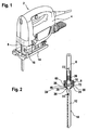
- the hand-held jigsaw 2 shown in the drawing comprises in a conventional manner a housing 4, an inside of the housing 4 arranged electric motor with a transmission (not shown), a linearly driven by the electric motor via the transmission, back and forth or up and down movable lifting rod 6, arranged at the free end of the lifting rod 6 jig 8 for clamping a head end 10 of a saw blade 12, and arranged between the jig 8 and an adjustable base plate 14 of the jigsaw 2 support roller unit 16 for supporting a saw blade back 18 of the saw blade 12th
- the clamping device 8 has a rigidly connected to the lower free end of the lifting rod 8 holder 20.
- the holder 20 is provided with a rectangular cross-section, downwardly open slot-shaped recess 22 into which the head end 10 of the saw blade 12 can be inserted from below and then locked in the holder 20.
- the head end 10 of the saw blade 12 is provided with two opposite lateral projections 24 and below the projections 24 with a narrowed neck portion 26, so that the projections 24 after insertion of the head end 10 of the saw blade 12 in the recess 22 of the holder 20 from the lower end face 28 of the holder 20 surrounding locking sleeve 30 can be engaged behind to hold the head end 10 of the saw blade 12 in the axial direction immovably in the recess 22.
- the holder 20 further has an upper part 32 with a larger diameter and a lower part 34 with a smaller diameter and is surrounded except for an upper dust cover 36 for the most part of the stepped stepped hollow cylindrical locking sleeve 30, which by means of a snap ring 38 about a longitudinal axis 40th the lifting rod 6 is rotatably mounted between two defined end positions on the holder 20.
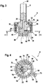
- the first, in 3 and 4 illustrated and referred to as a basic or initial position end position is the position in which the locking sleeve 30 is when no saw blade 12 is inserted into the recess 22 and no torque is applied by a user to the locking sleeve 30.
- the second, in FIGS. 5 and 6 illustrated end position is the removal position in which a rectangular slot opening 42 in the lower end face 28 of the locking sleeve 30 is aligned with the rectangular cross-section recess 22 in the holder 20, so that the head end 10 of the saw blade 12 including the projections 24 from below through the slot opening 42 can be inserted into the recess 22.
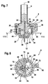
- FIGS. 7 and 8 illustrated locking position engage in the opposite edges of the slot opening 42 in the lower end face 28 of the locking sleeve 30, the two projections 24 of the saw blade 12, as best in Fig. 2 represented, and thereby prevent axial movement of the saw blade 12 from the recess 22.
- a pressure pin 46 is inserted transversely to the longitudinal axis 40 slidably.
- the pressure pin 46 serves to press the inserted into the recess 22 head 10 of the saw blade 12 in the locking position against a pressing pin 46 opposite boundary wall 48 of the recess 22 to the head end 10 of the saw blade 12 regardless of its thickness in a defined position against the Hold the boundary wall 48 fitting and thereby ensure a consistent and precise positioning of the saw blade 12.
- the pressure pin 46 must be displaced further into the recess 22, the thinner the saw blade 12 is.
- the rectangular cross-section Anpressbolzen 46 has on the underside of its protruding into the recess 22 inner end chamfer 50 so that it is displaced during insertion of the head end 10 of the saw blade 12 in the recess 22 to the outside until the head end 10 of the saw blade 12th between the free end of the Anpressbolzens 46 and the boundary wall 48 can pass through into the recess 22.
- the pressure pin 46 has an enlarged head portion 52 which projects into an annular space 54 between a cylindrical peripheral surface 56 of the lower part 34 of the holder 20 and the inside of an outer wall 58 of an enlarged upper part of the locking sleeve 30.
- a helically wound torsion spring 60 whose one end 62 is bent radially inwardly and opposite to the free end of the Anpressbolzens 46 in a radial receiving opening 64 in the lower part 34 of the holder 20 is inserted and the other end face 66 is bent radially outwardly and is inserted into a receiving opening 68 of a radially outwardly projecting beyond the outside of the locking sleeve 30 hollow projection 70.
- the torsion spring 60 has the task to rotate the locking sleeve 30 in the basic or initial position or in the locking position when the saw blade 12 has been removed in the removal position from the recess 22 of the holder 20 and inserted into the recess 22 of the holder 20 is and for rotating the locking sleeve 30 serving in the removal position, one-sided acting on the projection 70 unlocking lever (not shown) has been released by the user.
- the space 54 further serves to receive a cam member 72 integrally connected to the locking sleeve 30, which projects between the torsion spring 60 and the peripheral surface 56 of the lower portion 34 of the holder 20 from below into the space 54, as best in the Figures 3 . 5 and 6 shown.
- the cam element 72 has approximately the shape of a half spiral winding and is provided on its side facing the holder 20 with a cam surface 74 whose distance from the peripheral surface 56 of the lower part 34 of the holder 20 decreases in the counterclockwise direction.
- the pressure pin 46 is delivered by the force acting on its head part 52 cam surface 74 of the cam member 72 into the recess 22 and with its free end against the adjacent broad side of the inserted into the recess 22 head end 10 of the saw blade 12 and this in turn with its opposite broad side pressed against the adjacent boundary wall 48 of the recess 22 when the locking sleeve 30 of the torsion spring 60 in a clockwise direction, ie in the direction of the arrow in Fig. 4 , is rotated in the locked position.
- the cam element 72 has, in the vicinity of its one end face, a stop region 76 which in the basic or initial position against one side of the widened head part 52 of the pressure pin 46 abuts and a prevents further rotation of the cam member 72 and thus the locking sleeve 30 beyond the basic or initial position.
- the cam member 72 on the other side of the stop portion 76 on an extended end face 78 whose length is dimensioned so that it abuts in the removal position against a portion 80 of the torsion spring 60.
- This part 80 of the torsion spring 60 abuts against the end face 42 of the torsion spring 60 inserted into the receiving opening 64 and projects radially outwardly beyond the holder 22, extending transversely through the intermediate space 54.
Landscapes
- Engineering & Computer Science (AREA)
- Mechanical Engineering (AREA)
- Sawing (AREA)
- Soil Working Implements (AREA)
- Gripping Jigs, Holding Jigs, And Positioning Jigs (AREA)
- Body Structure For Vehicles (AREA)
Description
- Die Erfindung betrifft eine Einspannvorrichtung gemäß dem Oberbegriff des Anspruchs 1 sowie eine Hubsägemaschine gemäß dem Oberbegriff des Anspruchs 12.
- Einspannvorrichtungen zum Einspannen eines Sägeblatts in einer Hubsägemaschine dienen dazu, das Sägeblatt fest mit einer motorisch angetriebenen, hin und her bewegten Hubstange der Hubsägemaschine zu verbinden, wobei eine möglichst unbewegliche Arretierung des Sägeblatts mit einer definierten Lagebeziehung zur Halterung angestrebt wird, um ein gutes und präzises Sägeergebnis zu erzielen.
- Eine Einspannvorrichtung der eingangs genannten Art ist aus der
EP 1 236 530 B1 bekannt. Diese Einspannvorrichtung ermöglicht einerseits einen schnellen und einfachen Austausch des Sägeblatts und gestattet es andererseits, auch unterschiedlich dicke Sägeblätter unbeweglich und in einer definierten Lage in der schlitzförmigen Ausnehmung der Halterung festzuhalten, da die in derEP 1 236 530 B1 auch als Blattführung bezeichnete drehbare Verriegelungshülse zum einen beim Verdrehen aus der Entnahmestellung in die Verriegelungsstellung zwei seitliche Vorsprünge des Sägeblatts hintergreift, so dass sich dieses letztere nicht mehr aus der Ausnehmung der Halterung heraus bewegen kann, und zum anderen durch die Einwirkung der Kurvenfläche des Nockenelements auf das in einer Führungsöffnung der Halterung geführte Anpresselement dafür sorgt, dass dieses letzter gegen eine Breitseite des Sägeblatts angepresst wird, um das Sägeblatt mit der entgegengesetzten Breitseite gegen die benachbarte Begrenzungswand der Ausnehmung anzupressen und dadurch unabhängig von der Dicke des Sägeblatts für eine feste Fixierung zu sorgen. - Bei der bekannten Einspannvorrichtung ist das Nockenelement der Verriegelungshülse an beiden Stirnenden der Kurvenfläche mit Anschlagbereichen versehen, die jeweils von einem hakenförmig nach innen umgebogenen Endabschnitt des Nockenelements gebildet werden, das wiederum radial einwärts von der zylindrischen Torsionsfeder in einem ringförmigen Zwischenraum zwischen der zylindrischen äußeren Umfangsfläche eines Teils der Halterung und der Innenseite einer zylindrischen Außenwand der Verriegelungshülse angeordnet ist. Die beiden nach innen umgebogenen und als Anschlagbereiche dienenden Endabschnitte des Nockenelements schlagen von entgegengesetzten Seiten her gegen einen nach außen weisenden verdickten Kopfteil des Anpresselements an, wenn sich die Verriegelungshülse in der Entnahmestellung bzw. einer Grund- oder Ausgangsstellung befindet, in der kein Sägeblatt in der Halterung aufgenommen ist und von einem Benutzter keine Kraft auf die Verriegelungshülse aufgebracht wird. Auf diese Weise kann eine Drehung der Verriegelungshülse über diese beiden Endstellungen hinaus verhindert werden.
- Diese Anordnung hat jedoch zwei Nachteile: Wenn ein Benutzer die Verriegelungshülse mit Hilfe eines Schwenkhebel in die Entnahmestellung dreht und dabei kräftig auf den Schwenkhebel drückt, schlägt der eine umgebogene Endabschnitt des Nockenelements der Verriegelungshülse infolge der Hebelwirkung mit großer Kraft gegen den Kopfteil des Anpresselements an, was gegebenenfalls ein Verbiegen des Endabschnitts oder ein Verkanten des Anpresselements in der Führungsöffnung der Halterung zur Folge haben kann. Ein Verbiegen des Endabschnitts wird noch dadurch begünstigt, dass in der Entnahmestellung der Abstand zwischen der Kurvenfläche und dem Kopfteil des Anpresselements am größten ist, so dass der umgebogene Endabschnitt in radialer Richtung relativ weit nach innen über einen benachbarten Abschnitt des Nockenelements überstehen muss, damit er gegen den Kopfteil anschlägt. Der relativ große Überstand des umgebogenen Endabschnitts kann außerdem dazu führen, dass sich dieser im Ringspalt zwischen der äußeren Umfangsfläche der Halterung und dem inneren Umfang der zylindrischen Torsionsfeder verklemmt.
- Ausgehend hiervon liegt der Erfindung die Aufgabe zugrunde, die bekannte Einspannvorrichtung dahingehend zu verbessern, dass sich ein Überdrehen der Verriegelungshülse über die Entnahmestellung hinaus ohne die Gefahr eines Verkantens des Anpresselements bzw. ohne die Gefahr einer Beschädigung des mit der Kurvenfläche versehenen Nockenelements verhindern lässt.
- Diese Aufgabe wird erfindungsgemäß dadurch gelöst, dass der Anschlag mit einem Teil der Torsionsfeder zusammenwirkt, um ein Verdrehen der Verriegelungshülse über die Entnahmestellung hinaus zu verhindern.
- Vorzugsweise grenzt der mit dem Anschlag zusammenwirkende Teil der Torsionsfeder an ein in eine Aussparung der Halterung eingesetztes Stirnende der Torsionsfeder an, wobei der mit dem Anschlag zusammenwirkende Teil radial nach außen über die Halterung übersteht und den die Halterung umgebenden Ringspalt durchsetzt.
- Dies hat den Vorteil, dass derselbe Endabschnitt des mit der Kurvenfläche versehenen Nockenelements verwendet werden kann, um ein Verdrehen der Verriegelungshülse in einer Richtung über die Entnahmestellung hinaus zu verhindern und um ein Verdrehen der Verriegelungshülse in der entgegengesetzten Richtung über die Grund- oder Ausgangsstellung hinaus zu verhindern, in welche die Verriegelungshülse von der Torsionsfeder gedreht wird, wenn sich kein Sägeblatt in der Ausnehmung der Halterung befindet. In der Grund- oder Ausgangsstellung schlägt der Endabschnitt zweckmäßig wie bei der aus der
EP 1 236 530 B1 bekannten Einspannvorrichtung gegen eine Seite eines verdickten Kopfteils des Anpresselements an, um ein Verdrehen der Verriegelungshülse über die Grund- oder Ausgangsstellung hinaus zu verhindern. Mit anderen Worten braucht dann das mit der Kurvenfläche versehene Nockenelement nur an oder in der Nähe eines Stirnendes mit den Anschlagbereichen versehen werden, die für eine Begrenzung des Drehwinkels in beiden Drehrichtungen sorgen. - Außerdem braucht das Stirnende des Nockenelements zur Bildung des mit der Torsionsfeder in Anschlag tretenden Anschlagbereichs nicht umgebogen werden, wodurch seine Verformungsfestigkeit verbessert werden kann. Eine besonders große Festigkeit wird erreicht, wenn das Stirnende des Nockenelements etwas über das in der Grund- oder Ausgangsstellung mit dem Kopfteil des Anpresselements in Anschlag tretenden Anschlagbereich hinaus verlängert und gegebenenfalls etwas verdickt ausgebildet wird, wobei dieses Stirnende dann den mit der Torsionsfeder in Anschlag tretenden Anschlagbereich bildet. Da das Stirnende im Wesentlichen in Bewegungsrichtung des Nockenelements ausgerichtet ist, wenn es gegen die Torsionsfeder anschlägt, weist das Nockenelement in Anschlagrichtung eine große Steifigkeit auf.
- Die Winkelposition, in der das Stirnende des Nockenelements mit der Torsionsfeder in Anschlag tritt, kann entweder durch eine Veränderung der Winkelausrichtung der zur Aufnahme des Stirnendes der Torsionsfeder dienenden Öffnung der Halterung und/oder durch eine entsprechende Verlängerung des Stirnendes des Nockenelements über den in der Grund- oder Ausgangsstellung als Anschlagbereich dienenden Abschnitt hinaus erreicht werden.
- Alternativ wäre es jedoch auch denkbar, in der Grund- oder Ausgangsstellung das entgegengesetzte Stirnende des Nockenelements als Anschlag zur Begrenzung der Drehbewegung der Verriegelungshülse zu verwenden, indem das Nockenelement an diesem Ende so weit verlängert wird, so dass es in der Grund- oder Ausgangsstellung von der entgegengesetzten Seite her gegen den in der Entnahmestellung als Anschlag für das Nockenelement dienenden Teil der Torsionsfeder anschlägt.
- Im folgenden wird die Erfindung anhand eines in der Zeichnung dargestellten Ausführungsbeispiels näher erläutert. Es zeigen:
-
Fig. 1 : eine perspektivische Ansicht einer Stichsäge mit einem eingespanntem Sägeblatt; -
Fig. 2 : eine Längsschnittansicht einer Hubstange und einer Einspannvorrichtung der Stichsäge mit Sägeblatt; -
Fig. 3 : eine vergrößerte Schnittansicht der Einspannvorrichtung entlang der Linie III-III derFig. 2 , jedoch ohne ein eingespanntes Sägeblatt und in einer Grund- oder Ausgangsstellung einer Verriegelungshülse; -
Fig. 4 : eine vergrößerte Querschnittsansicht der Einspannvorrichtung entlang der Linie IV-IV derFig. 3 ; -
Fig. 5 : eine vergrößerte Schnittansicht der Einspannvorrichtung ohne ein eingespanntes Sägeblatt entsprechendFig. 3 , jedoch in einer Entnahmestellung der Verriegelungshülse. -
Fig. 6 : eine vergrößerte Querschnittsansicht der Einspannvorrichtung entlang der Linie VI-VI derFig. 5 ; -
Fig. 7 : eine vergrößerte Schnittansicht der Einspannvorrichtung entsprechendFig. 3 und5 , jedoch mit einem eingespannten Sägeblatt und in einer Verriegelungsstellung der Verriegelungshülse; -
Fig. 8 : eine vergrößerte Querschnittsansicht der Einspannvorrichtung entlang der Linie VIII-VIII derFig. 7 . - Die in
Fig. 1 der Zeichnung dargestellte handgeführte Stichsäge 2 umfasst in an sich bekannter Weise ein Gehäuse 4, einen innerhalb des Gehäuses 4 angeordneten Elektromotor mit einem Getriebe (nicht dargestellt), eine vom Elektromotor über das Getriebe linear angetriebene, hin und her bzw. auf und ab bewegliche Hubstange 6, eine am freien Ende der Hubstange 6 angeordnete Einspannvorrichtung 8 zum Einspannen eines Kopfendes 10 eines Sägeblatts 12, sowie eine zwischen der Einspannvorrichtung 8 und einer verstellbaren Fußplatte 14 der Stichsäge 2 angeordnete Stützrolleneinheit 16 zum Abstützen eines Sägeblattrückens 18 des Sägeblatts 12. - Wie am besten in den
Figuren 3 bis 8 dargestellt, weist die Einspannvorrichtung 8 eine starr mit dem unteren freien Ende der Hubstange 8 verbundene Halterung 20 auf. Die Halterung 20 ist mit einer im Querschnitt rechteckigen, nach unten zu offenen schlitzförmigen Ausnehmung 22 versehen, in die sich das Kopfende 10 des Sägeblatts 12 von unten her einführen und dann in der Halterung 20 verriegeln lässt. - Wie in
Fig. 2 dargestellt, ist zu diesem Zweck das Kopfende 10 des Sägeblatts 12 mit zwei entgegengesetzten seitlichen Vorsprüngen 24 und unterhalb der Vorsprünge 24 mit einem verengten Halsabschnitt 26 versehen, so dass die Vorsprünge 24 nach dem Einführen des Kopfendes 10 des Sägeblatts 12 in die Ausnehmung 22 der Halterung 20 vom unteren Stirnende 28 einer die Halterung 20 umgebenden Verriegelungshülse 30 hintergriffen werden können, um das Kopfende 10 des Sägeblatts 12 in axialer Richtung unverschiebbar in der Ausnehmung 22 festzuhalten. - Die Halterung 20 weist weiter einen oberen Teil 32 mit größerem Durchmesser und einen unteren Teil 34 mit kleinerem Durchmesser auf und wird abgesehen von einer oberen Staubschutzkappe 36 zum überwiegenden Teil von der stufenförmig abgesetzten hohlzylindrischen Verriegelungshülse 30 umschlossen, die mittels eines Sprengrings 38 um eine Längsachse 40 der Hubstange 6 zwischen zwei definierten Endstellungen drehbar an der Halterung 20 befestigt ist.
- Die erste, in
Fig. 3 und 4 dargestellte und als Grund- oder Ausgangsstellung bezeichnete Endstellung ist die Stellung, in der sich die Verriegelungshülse 30 befindet, wenn kein Sägeblatt 12 in die Ausnehmung 22 eingesetzt ist und keine Drehkraft von einem Benutzer auf die Verriegelungshülse 30 aufgebracht wird. - Die zweite, in
Fig. 5 und 6 dargestellte Endstellung ist die Entnahmestellung, in der eine rechteckige Schlitzöffnung 42 im unteren Stirnende 28 der Verriegelungshülse 30 mit der im Querschnitt rechteckigen Ausnehmung 22 in der Halterung 20 fluchtet, so dass sich das Kopfende 10 des Sägeblatts 12 einschließlich der Vorsprünge 24 von unten durch die Schlitzöffnung 42 in die Ausnehmung 22 einführen lässt. - Zwischen der Grund- oder Ausgangsstellung und der Entnahmestellung liegt die in
Fig. 7 und 8 dargestellte Verriegelungsstellung, in der gegenüberliegende Ränder der Schlitzöffnung 42 im unteren Stirnende 28 der Verriegelungshülse 30 die beiden Vorsprünge 24 des Sägeblatts 12 hintergreifen, wie am besten inFig. 2 dargestellt, und dadurch eine axiale Bewegung des Sägeblatts 12 aus der Ausnehmung 22 verhindern. - Im unteren Teil der Halterung 20 befindet sich eine quer zur Längsachse 40 der Hubstange 6 ausgerichtete Führungsöffnung 44, in die ein Anpressbolzen 46 quer zur Längsachse 40 verschiebbar eingesetzt ist. Der Anpressbolzen 46 dient dazu, das in die Ausnehmung 22 eingeführte Kopfende 10 des Sägeblatts 12 in der Verriegelungsstellung gegen eine dem Anpressbolzen 46 gegenüberliegende Begrenzungswand 48 der Ausnehmung 22 anzupressen, um das Kopfende 10 des Sägeblatts 12 unabhängig von seiner Dicke in einer definierten Lage gegen die Begrenzungswand 48 anliegend festzuhalten und dadurch für eine gleichbleibende und präzise Positionierung des Sägeblatts 12 zu sorgen. Dazu muss der Anpressbolzen 46 umso weiter in die Ausnehmung 22 hinein verschoben werden, je dünner das Sägeblatt 12 ist.
- Der im Querschnitt rechteckige Anpressbolzen 46 weist an der Unterseite seines in die Ausnehmung 22 ragenden inneren Endes eine Abschrägung 50 auf, so dass er beim Einführen des Kopfendes 10 des Sägeblatts 12 in die Ausnehmung 22 nach außen verschoben wird, bis das Kopfende 10 des Sägeblatts 12 zwischen dem freien Ende des Anpressbolzens 46 und der Begrenzungswand 48 hindurch in die Ausnehmung 22 eintreten kann. Weiter weist der Anpressbolzen 46 einen erweiterten Kopfteil 52 auf, der in einen ringförmigen Zwischenraum 54 zwischen einer zylindrischen Umfangsfläche 56 des unteren Teils 34 der Halterung 20 und der Innenseite einer Außenwand 58 eines erweiterten Oberteils der Verriegelungshülse 30 ragt.
- In diesem Zwischenraum 54 befindet sich eine schraubenförmig gewickelte Torsionsfeder 60, deren eines Stirnende 62 radial nach innen umgebogen und gegenüber vom freien Ende des Anpressbolzens 46 in eine radiale Aufnahmeöffnung 64 im unteren Teil 34 der Halterung 20 eingeführt ist und deren anderes Stirnende 66 radial nach außen umgebogen ist und in eine Aufnahmeöffnung 68 eines radial nach außen über die Außenseite der Verriegelungshülse 30 überstehenden hohlen Vorsprungs 70 eingeführt ist. Die Torsionsfeder 60 hat die Aufgabe, die Verriegelungshülse 30 in die Grund- oder Ausgangsstellung bzw. in die Verriegelungsstellung zu drehen, wenn das Sägeblatt 12 in der Entnahmestellung aus der Ausnehmung 22 der Halterung 20 entnommen bzw. in die Ausnehmung 22 der Halterung 20 eingesetzt worden ist und ein zum Verdrehen der Verriegelungshülse 30 in die Entnahmestellung dienender, einseitig auf den Vorsprung 70 einwirkender Entriegelungshebel (nicht dargestellt) vom Benutzer losgelassen worden ist.
- Der Zwischenraum 54 dient weiter zur Aufnahme eines einstückig mit der Verriegelungshülse 30 verbundenen Nockenelements 72, das zwischen der Torsionsfeder 60 und der Umfangsfläche 56 des unteren Teils 34 der Halterung 20 von unten her in den Zwischenraum 54 ragt, wie am besten in den
Figuren 3 ,5 und 6 dargestellt. Das Nockenelement 72 weist etwa die Form einer halben Spiralwindung auf und ist an seiner der Halterung 20 zugewandten Innenseite mit einer Kurvenfläche 74 versehen, deren Abstand von der Umfangsfläche 56 des unteren Teils 34 der Halterung 20 entgegen dem Uhrzeigersinn abnimmt. Dadurch wird der Anpressbolzen 46 von der auf seinen Kopfteil 52 einwirkenden Kurvenfläche 74 des Nockenelements 72 in die Ausnehmung 22 hinein zugestellt und mit seinem freien Ende gegen die benachbarte Breitseite des in die Ausnehmung 22 eingeführten Kopfendes 10 des Sägeblatts 12 und dieses wiederum mit seiner entgegengesetzten Breitseite gegen die benachbarte Begrenzungswand 48 der Ausnehmung 22 angepresst, wenn die Verriegelungshülse 30 von der Torsionsfeder 60 im Uhrzeigersinn, d.h. in Richtung des Pfeils inFig. 4 , in die Verriegelungsstellung gedreht wird. - Um zu verhindern, dass die Verriegelungshülse 30 von der Torsionsfeder 60 über die in
Fig. 3 und 4 dargestellte Grund- oder Ausgangsstellung hinaus gedreht wird, wenn kein Sägeblatt 12 in die Ausnehmung 22 eingeführt worden ist, weist das Nockenelement 72 in der Nähe seines einen Stirnendes einen Anschlagbereich 76 auf, der in der Grund- oder Ausgangsstellung gegen eine Seite des erweiterten Kopfteils 52 des Anpressbolzens 46 anschlägt und eine weitere Drehung des Nockenelements 72 und damit der Verriegelungshülse 30 über die Grund- oder Ausgangsstellung hinaus verhindert. - Um zu verhindern, dass die Verriegelungshülse 30 beim Austausch des Sägeblatts 12 vom Benutzer entgegen dem Uhrzeigersinn über die in
Fig. 5 und 6 dargestellte Entnahmestellung hinaus gedreht wird, weist das Nockenelement 72 jenseits des Anschlagbereichs 76 ein verlängertes Stirnende 78 auf, dessen Länge so bemessen ist, dass es in der Entnahmestellung gegen einen Teil 80 der Torsionsfeder 60 anschlägt. Dieser Teil 80 der Torsionsfeder 60 grenzt an das in die Aufnahmeöffnung 64 eingesetzte Stirnende 42 der Torsionsfeder 60 an und steht radial nach außen über die Halterung 22 über, wobei er sich quer durch den Zwischenraum 54 erstreckt. - Durch Veränderung der Länge des über den Anschlagbereich 76 überstehenden Stirnendes 78 des Nockenelements 72 ist es möglich, einen gewünschten Drehwinkel der Verriegelungshülse 30 zwischen der Entnahmestellung und der Grund- oder Ausgangsstellung einzustellen.
- Zur Veränderung dieses Drehwinkels wäre es aber auch möglich, die in der Halterung 22 ausgesparte Aufnahmeöffnung 62 für das Stirnende 42 der Torsionsfeder 60 statt genau gegenüber von der Führungsöffnung 44 des Anpressbolzens 46 in Bezug zur Achse 40 unter einem anderen Winkel zu dieser Öffnung 44 anzuordnen.
- Weiter ist es möglich, auf den Anschlagbereich 76 zu verzichten und das zum Stirnende 78 entgegengesetzte Stirnende 82 des Nockenelements 72 so weit zu verlängern, dass es in der Grund- oder Ausgangsstellung gegen die entgegengesetzte Seite des Teils 80 der Torsionsfeder 60 anschlägt (nicht dargestellt).
Claims (12)
- Einspannvorrichtung zum Verbinden eines Sägeblatts (12) mit einer Hubstange (6) einer Hubsägemaschine, insbesondere einer handgeführte Stichsäge, umfassend eine mit der Hubstange (6) verbundene Halterung (20), die eine Ausnehmung (22) zur Aufnahme eines Kopfendes (10) des Sägeblatts (12) aufweist, eine Verriegelungshülse (30), die in Bezug zur Halterung entgegen der Kraft einer Torsionsfeder (60) um die Achse drehbar ist, um das Kopfende (10) des Sägeblatts (12) in einer Verriegelungsstellung in der Ausnehmung (22) zu verriegeln und in einer Entnahmestellung eine Entnahme des Sägeblatts (12) zu erlauben, dadurch gekennzeichnet, dass ein Anschlag (78) mit einem Teil (80) der Torsionsfeder (60) zusammenwirkt, um die Bewegung der Verriegelungshülse (30) über die Entnahmestellung hinaus zu verhindern.
- Einspannvorrichtung nach Anspruch 1, dadurch gekennzeichnet, dass der mit dem Anschlag (78) zusammenwirkende Teil (80) der Torsionsfeder (60) im Wesentlichen radial zur Achse (40) ausgerichtet ist.
- Einspannvorrichtung nach Anspruch 1 oder 2, dadurch gekennzeichnet, dass der mit dem Anschlag (78) zusammenwirkende Teil (80) der Torsionsfeder (60) nach außen über einen Teil (34) der Halterung (22) übersteht.
- Einspannvorrichtung nach einem der vorangehenden Ansprüche, dadurch gekennzeichnet, dass der mit dem Anschlag (78) zusammenwirkende Teil (80) der Torsionsfeder (60) an ein in eine Aussparung (62) der Halterung (22) eingesetztes Stirnende (62) der Torsionsfeder (60) angrenzt.
- Einspannvorrichtung nach einem der vorangehenden Ansprüche, dadurch gekennzeichnet, dass die Hubstange (6) entlang einer Achse (40) hin und her beweglich ist.
- Einspannvorrichtung nach einem der vorangehenden Ansprüche, gekennzeichnet durch ein Anpresselement (46) zum Anpressen des Sägeblatts (12) gegen eine seitliche Begrenzungswand (48) der Ausnehmung (22).
- Einspannvorrichtung nach Anspruch 6, dadurch gekennzeichnet, dass das Anpresselement (46) in Bezug zur Halterung (20) quer zur Achse (40) beweglich ist
- Einspannvorrichtung nach Anspruch 6 oder 7, dadurch gekennzeichnet, dass die Verriegelungshülse (30) mit einer Kurvenfläche (74) eines Nockenelements (72) auf das Anpresselement (46) einwirkt, um das Sägeblatt (12) in der Verriegelungsstellung gegen die Begrenzungswand (48) der Ausnehmung (22) anzupressen.
- Einspannvorrichtung nach Anspruch 8, dadurch gekennzeichnet, dass das Nockenelement (72) mit einem Anschlag (78) versehen ist, der eine Bewegung der Verriegelungshülse (30) über die Entnahmestellung hinaus verhindert,
- Einspannvorrichtung nach Anspruch 9, dadurch gekennzeichnet, dass der Anschlag (78) von einem Stirnende (78) des Nockenelements (72) gebildet wird, das im Wesentlichen in Bewegungsrichtung des Nockenelements (72) weist.
- Einspannvorrichtung nach einem der Ansprüche 8 bis 10, dadurch gekennzeichnet, dass das Nockenelement (72) mit einem Anschlagbereich (76) versehen ist, der eine Bewegung der Verriegelungshülse (30) über eine Grund-oder Ausgangsstellung hinaus verhindert, und dass der Anschlag (78) und der Anschlagbereich (76) nahe beieinander auf dem Nockenelement (72) angeordnet sind.
- Hubsägemaschine, insbesondere handgeführte Stichsäge, gekennzeichnet durch eine Einspannvorrichtung nach einem der vorangehenden Ansprüche.
Applications Claiming Priority (2)
| Application Number | Priority Date | Filing Date | Title |
|---|---|---|---|
| DE102006043682A DE102006043682A1 (de) | 2006-09-18 | 2006-09-18 | Einspannvorrichtung für eine Hubsägemaschine |
| PCT/EP2007/057891 WO2008034666A1 (de) | 2006-09-18 | 2007-07-31 | Einspannvorrichtung für eine hubsägemaschine |
Publications (2)
| Publication Number | Publication Date |
|---|---|
| EP2069094A1 EP2069094A1 (de) | 2009-06-17 |
| EP2069094B1 true EP2069094B1 (de) | 2010-01-20 |
Family
ID=38656519
Family Applications (1)
| Application Number | Title | Priority Date | Filing Date |
|---|---|---|---|
| EP07788086A Active EP2069094B1 (de) | 2006-09-18 | 2007-07-31 | Einspannvorrichtung für eine hubsägemaschine |
Country Status (7)
| Country | Link |
|---|---|
| US (1) | US8024865B2 (de) |
| EP (1) | EP2069094B1 (de) |
| CN (1) | CN101516557B (de) |
| AT (1) | ATE455617T1 (de) |
| DE (2) | DE102006043682A1 (de) |
| RU (1) | RU2438840C2 (de) |
| WO (1) | WO2008034666A1 (de) |
Families Citing this family (21)
| Publication number | Priority date | Publication date | Assignee | Title |
|---|---|---|---|---|
| DE102006043682A1 (de) * | 2006-09-18 | 2008-03-27 | Robert Bosch Gmbh | Einspannvorrichtung für eine Hubsägemaschine |
| DE102007026444A1 (de) * | 2007-06-06 | 2008-12-11 | Robert Bosch Gmbh | Handhubsägemaschine mit Spannvorrichtung für ein hin- und herbewegbares Werkzeug, insbesondere Hubsägeblatt |
| DE102008055065B4 (de) * | 2008-12-22 | 2021-11-04 | Robert Bosch Gmbh | Handwerkzeugmaschinenvorrichtung mit Luftleitelement |
| US8800999B2 (en) * | 2009-02-27 | 2014-08-12 | Black & Decker Inc. | Bit retention device |
| US8555516B2 (en) | 2010-03-25 | 2013-10-15 | Black & Decker Inc. | Pivoting blade retainer |
| EP2694260B1 (de) | 2011-04-01 | 2017-01-18 | Milwaukee Electric Tool Corporation | Stichsäge |
| CN103203497B (zh) * | 2012-01-16 | 2017-05-03 | 博世电动工具(中国)有限公司 | 锯片夹持装置 |
| US8978253B2 (en) * | 2012-04-30 | 2015-03-17 | Spyderco, Inc. | Modular spring assembly for a folding tool |
| US9492916B2 (en) | 2012-04-30 | 2016-11-15 | Spyderco, Inc. | Locking mechanism for a push button activated folding tool |
| US9592612B2 (en) | 2012-05-17 | 2017-03-14 | Spyderco, Inc. | Split spring locking feature for a folding tool |
| JP5921385B2 (ja) * | 2012-08-22 | 2016-05-24 | 株式会社マキタ | レシプロソー |
| DE102013208132A1 (de) * | 2013-05-03 | 2014-11-06 | Robert Bosch Gmbh | Handwerkzeugmaschine |
| US9327413B2 (en) | 2013-11-11 | 2016-05-03 | Spyderco, Inc. | Folding knife with a two-piece backlock |
| US9943970B2 (en) | 2014-11-14 | 2018-04-17 | Spyderco, Inc. | Rotational wedge locking mechanism for a folding knife |
| USD818331S1 (en) * | 2017-03-23 | 2018-05-22 | 7Rdd Limited | Jigsaw |
| USD863015S1 (en) * | 2018-04-18 | 2019-10-15 | Black & Decker Inc. | Jigsaw |
| DE102018125175B4 (de) * | 2018-10-11 | 2026-02-26 | Mafell Ag | Stichsäge |
| US11738397B2 (en) | 2019-06-12 | 2023-08-29 | Black & Decker Inc. | Reciprocating saw |
| JP6697624B1 (ja) | 2019-11-12 | 2020-05-20 | 純平 間狩 | 折り畳み式ナイフ |
| KR102578164B1 (ko) * | 2020-12-29 | 2023-09-19 | 계양전기 주식회사 | 전동공구의 블레이드 탈착 구조 |
| US12420345B2 (en) | 2022-02-22 | 2025-09-23 | Techtronic Cordless Gp | Blade clamp for reciprocating saw |
Family Cites Families (12)
| Publication number | Priority date | Publication date | Assignee | Title |
|---|---|---|---|---|
| SU1348174A1 (ru) * | 1985-10-23 | 1987-10-30 | Всесоюзный конструкторско-технологический институт по механизации монтажных и специальных строительных работ | Приспособление дл распиливани |
| DE4138986A1 (de) * | 1991-11-27 | 1993-06-03 | Atlas Copco Elektrowerkzeuge | Spanneinrichtung fuer eine stichsaegemaschine |
| DE19509539A1 (de) * | 1995-03-16 | 1996-09-19 | Bosch Gmbh Robert | Stichsägemaschine |
| RU2763U1 (ru) * | 1995-05-19 | 1996-09-16 | Сергей Иванович Квашнин | Лобзик |
| US6725548B1 (en) * | 1996-03-01 | 2004-04-27 | Milwaukee Electric Tool Corporation | Keyless blade clamp mechanism |
| US6053675A (en) * | 1998-06-26 | 2000-04-25 | Black & Decker Inc. | Quick-acting tool bit holder |
| US6209208B1 (en) * | 1998-10-09 | 2001-04-03 | Milwaukee Electric Tool Corporarion | Keyless blade clamp mechanism |
| US6735876B2 (en) * | 2001-03-01 | 2004-05-18 | Makita Corporation | Blade clamps suitable for reciprocating power tools |
| CN2617509Y (zh) * | 2003-04-14 | 2004-05-26 | 苏州宝时得电动工具有限公司 | 工作元件的快换夹紧机构 |
| US7871080B2 (en) * | 2004-01-16 | 2011-01-18 | Robert Bosch Gmbh | Tool-less blade clamping apparatus for a reciprocating tool |
| DE102006043682A1 (de) * | 2006-09-18 | 2008-03-27 | Robert Bosch Gmbh | Einspannvorrichtung für eine Hubsägemaschine |
| DE102007009943B3 (de) * | 2007-03-01 | 2008-06-19 | Festool Gmbh | Hubsäge, insbesondere Stichsäge |
-
2006
- 2006-09-18 DE DE102006043682A patent/DE102006043682A1/de not_active Withdrawn
-
2007
- 2007-07-31 EP EP07788086A patent/EP2069094B1/de active Active
- 2007-07-31 CN CN200780034489.2A patent/CN101516557B/zh active Active
- 2007-07-31 AT AT07788086T patent/ATE455617T1/de active
- 2007-07-31 DE DE502007002700T patent/DE502007002700D1/de active Active
- 2007-07-31 US US12/094,662 patent/US8024865B2/en active Active
- 2007-07-31 RU RU2009114416/02A patent/RU2438840C2/ru not_active IP Right Cessation
- 2007-07-31 WO PCT/EP2007/057891 patent/WO2008034666A1/de not_active Ceased
Also Published As
| Publication number | Publication date |
|---|---|
| WO2008034666A1 (de) | 2008-03-27 |
| US20080289198A1 (en) | 2008-11-27 |
| DE502007002700D1 (de) | 2010-03-11 |
| CN101516557A (zh) | 2009-08-26 |
| DE102006043682A1 (de) | 2008-03-27 |
| RU2438840C2 (ru) | 2012-01-10 |
| RU2009114416A (ru) | 2010-10-27 |
| CN101516557B (zh) | 2011-06-15 |
| EP2069094A1 (de) | 2009-06-17 |
| US8024865B2 (en) | 2011-09-27 |
| ATE455617T1 (de) | 2010-02-15 |
Similar Documents
| Publication | Publication Date | Title |
|---|---|---|
| WO2008034666A1 (de) | Einspannvorrichtung für eine hubsägemaschine | |
| DE60205146T2 (de) | Blattaufspannvorrichtung für ein in axialer Richtung hin- und herbewegbares Kraftwerkzeug | |
| EP0623413B1 (de) | Schnellspannvorrichtung für Stichsägeblätter | |
| DE112012003011B4 (de) | Verstellvorrichtung für einen Kraftfahrzeugsitz | |
| WO2008148593A1 (de) | Handhubsägemaschine mit spannvorrichtung für ein hin- und herbewegbares werkzeug, insbesondere hubsägeblatt | |
| EP2262619A1 (de) | Zusatzhandgriff sowie handwerkzeugmaschine | |
| DE20113307U1 (de) | Ratschenschlüssel | |
| EP3341264B1 (de) | Klemmvorrichtung einer verstellbaren lenksäule für kraftfahrzeuge | |
| EP1964635A2 (de) | Hubsäge, insbesondere Stichsäge | |
| EP1974866B1 (de) | Spindelarretierung eines handgeführten Bohr- und Meißelhammers | |
| EP2965843B1 (de) | Spannfutter und spannmittel mit schnellwechselfunktion | |
| EP1857223A1 (de) | Oszillationsantrieb mit einem Tiefenanschlag und Tiefenanschlag für einen Oszillationsantrieb | |
| EP1900483A2 (de) | Vorspanneinrichtung zum Vorspannen einer Schraubenfelder | |
| WO2009153166A1 (de) | Klemmvorrichtung zur lagefixierung einer verstellbaren fahrzeuglenksäule | |
| EP2554314B1 (de) | Handgeführte Säge sowie Blattspannmechanismus hierfür | |
| EP1905545A2 (de) | Federspanner für Schraubenfedern | |
| EP1627394B1 (de) | Haptische begrenzung für einen stufenschalter oder ein potentiometer | |
| DE2730475A1 (de) | Einstellantrieb fuer feinmechanische geraete, insbesondere thermostate | |
| EP2357052A1 (de) | Handbetätigtes Werkzeug | |
| EP1172167B1 (de) | Spanneinrichtung für Werkzeug mit auswechselbaren Sägeblättern | |
| EP3733336B1 (de) | Klemmhalter | |
| DE9305188U1 (de) | Schnellspannvorrichtung für Stichsägeblätter | |
| EP3476655B1 (de) | Trägereinheit für eine dachträgeranordnung eines kraftfahrzeugs | |
| DE10247566B4 (de) | Radialrollkopf | |
| EP3540156A1 (de) | Drückerlagerung |
Legal Events
| Date | Code | Title | Description |
|---|---|---|---|
| PUAI | Public reference made under article 153(3) epc to a published international application that has entered the european phase |
Free format text: ORIGINAL CODE: 0009012 |
|
| 17P | Request for examination filed |
Effective date: 20090420 |
|
| AK | Designated contracting states |
Kind code of ref document: A1 Designated state(s): AT BE BG CH CY CZ DE DK EE ES FI FR GB GR HU IE IS IT LI LT LU LV MC MT NL PL PT RO SE SI SK TR |
|
| AX | Request for extension of the european patent |
Extension state: AL BA HR MK RS |
|
| GRAP | Despatch of communication of intention to grant a patent |
Free format text: ORIGINAL CODE: EPIDOSNIGR1 |
|
| GRAS | Grant fee paid |
Free format text: ORIGINAL CODE: EPIDOSNIGR3 |
|
| GRAA | (expected) grant |
Free format text: ORIGINAL CODE: 0009210 |
|
| AK | Designated contracting states |
Kind code of ref document: B1 Designated state(s): AT BE BG CH CY CZ DE DK EE ES FI FR GB GR HU IE IS IT LI LT LU LV MC MT NL PL PT RO SE SI SK TR |
|
| REG | Reference to a national code |
Ref country code: GB Ref legal event code: FG4D Free format text: NOT ENGLISH |
|
| REG | Reference to a national code |
Ref country code: CH Ref legal event code: EP |
|
| REG | Reference to a national code |
Ref country code: IE Ref legal event code: FG4D |
|
| REF | Corresponds to: |
Ref document number: 502007002700 Country of ref document: DE Date of ref document: 20100311 Kind code of ref document: P |
|
| REG | Reference to a national code |
Ref country code: NL Ref legal event code: VDEP Effective date: 20100120 |
|
| LTIE | Lt: invalidation of european patent or patent extension |
Effective date: 20100120 |
|
| PG25 | Lapsed in a contracting state [announced via postgrant information from national office to epo] |
Ref country code: PT Free format text: LAPSE BECAUSE OF FAILURE TO SUBMIT A TRANSLATION OF THE DESCRIPTION OR TO PAY THE FEE WITHIN THE PRESCRIBED TIME-LIMIT Effective date: 20100520 Ref country code: LT Free format text: LAPSE BECAUSE OF FAILURE TO SUBMIT A TRANSLATION OF THE DESCRIPTION OR TO PAY THE FEE WITHIN THE PRESCRIBED TIME-LIMIT Effective date: 20100120 Ref country code: NL Free format text: LAPSE BECAUSE OF FAILURE TO SUBMIT A TRANSLATION OF THE DESCRIPTION OR TO PAY THE FEE WITHIN THE PRESCRIBED TIME-LIMIT Effective date: 20100120 Ref country code: IS Free format text: LAPSE BECAUSE OF FAILURE TO SUBMIT A TRANSLATION OF THE DESCRIPTION OR TO PAY THE FEE WITHIN THE PRESCRIBED TIME-LIMIT Effective date: 20100520 Ref country code: ES Free format text: LAPSE BECAUSE OF FAILURE TO SUBMIT A TRANSLATION OF THE DESCRIPTION OR TO PAY THE FEE WITHIN THE PRESCRIBED TIME-LIMIT Effective date: 20100501 |
|
| REG | Reference to a national code |
Ref country code: IE Ref legal event code: FD4D |
|
| PG25 | Lapsed in a contracting state [announced via postgrant information from national office to epo] |
Ref country code: SI Free format text: LAPSE BECAUSE OF FAILURE TO SUBMIT A TRANSLATION OF THE DESCRIPTION OR TO PAY THE FEE WITHIN THE PRESCRIBED TIME-LIMIT Effective date: 20100120 Ref country code: PL Free format text: LAPSE BECAUSE OF FAILURE TO SUBMIT A TRANSLATION OF THE DESCRIPTION OR TO PAY THE FEE WITHIN THE PRESCRIBED TIME-LIMIT Effective date: 20100120 Ref country code: FI Free format text: LAPSE BECAUSE OF FAILURE TO SUBMIT A TRANSLATION OF THE DESCRIPTION OR TO PAY THE FEE WITHIN THE PRESCRIBED TIME-LIMIT Effective date: 20100120 Ref country code: LV Free format text: LAPSE BECAUSE OF FAILURE TO SUBMIT A TRANSLATION OF THE DESCRIPTION OR TO PAY THE FEE WITHIN THE PRESCRIBED TIME-LIMIT Effective date: 20100120 |
|
| PG25 | Lapsed in a contracting state [announced via postgrant information from national office to epo] |
Ref country code: GR Free format text: LAPSE BECAUSE OF FAILURE TO SUBMIT A TRANSLATION OF THE DESCRIPTION OR TO PAY THE FEE WITHIN THE PRESCRIBED TIME-LIMIT Effective date: 20100421 Ref country code: CY Free format text: LAPSE BECAUSE OF FAILURE TO SUBMIT A TRANSLATION OF THE DESCRIPTION OR TO PAY THE FEE WITHIN THE PRESCRIBED TIME-LIMIT Effective date: 20100120 Ref country code: SE Free format text: LAPSE BECAUSE OF FAILURE TO SUBMIT A TRANSLATION OF THE DESCRIPTION OR TO PAY THE FEE WITHIN THE PRESCRIBED TIME-LIMIT Effective date: 20100120 Ref country code: RO Free format text: LAPSE BECAUSE OF FAILURE TO SUBMIT A TRANSLATION OF THE DESCRIPTION OR TO PAY THE FEE WITHIN THE PRESCRIBED TIME-LIMIT Effective date: 20100120 Ref country code: EE Free format text: LAPSE BECAUSE OF FAILURE TO SUBMIT A TRANSLATION OF THE DESCRIPTION OR TO PAY THE FEE WITHIN THE PRESCRIBED TIME-LIMIT Effective date: 20100120 Ref country code: IE Free format text: LAPSE BECAUSE OF FAILURE TO SUBMIT A TRANSLATION OF THE DESCRIPTION OR TO PAY THE FEE WITHIN THE PRESCRIBED TIME-LIMIT Effective date: 20100120 |
|
| PLBE | No opposition filed within time limit |
Free format text: ORIGINAL CODE: 0009261 |
|
| STAA | Information on the status of an ep patent application or granted ep patent |
Free format text: STATUS: NO OPPOSITION FILED WITHIN TIME LIMIT |
|
| PG25 | Lapsed in a contracting state [announced via postgrant information from national office to epo] |
Ref country code: BG Free format text: LAPSE BECAUSE OF FAILURE TO SUBMIT A TRANSLATION OF THE DESCRIPTION OR TO PAY THE FEE WITHIN THE PRESCRIBED TIME-LIMIT Effective date: 20100420 Ref country code: SK Free format text: LAPSE BECAUSE OF FAILURE TO SUBMIT A TRANSLATION OF THE DESCRIPTION OR TO PAY THE FEE WITHIN THE PRESCRIBED TIME-LIMIT Effective date: 20100120 Ref country code: CZ Free format text: LAPSE BECAUSE OF FAILURE TO SUBMIT A TRANSLATION OF THE DESCRIPTION OR TO PAY THE FEE WITHIN THE PRESCRIBED TIME-LIMIT Effective date: 20100120 |
|
| 26N | No opposition filed |
Effective date: 20101021 |
|
| BERE | Be: lapsed |
Owner name: ROBERT BOSCH G.M.B.H. Effective date: 20100731 |
|
| PG25 | Lapsed in a contracting state [announced via postgrant information from national office to epo] |
Ref country code: DK Free format text: LAPSE BECAUSE OF FAILURE TO SUBMIT A TRANSLATION OF THE DESCRIPTION OR TO PAY THE FEE WITHIN THE PRESCRIBED TIME-LIMIT Effective date: 20100120 |
|
| PG25 | Lapsed in a contracting state [announced via postgrant information from national office to epo] |
Ref country code: MC Free format text: LAPSE BECAUSE OF NON-PAYMENT OF DUE FEES Effective date: 20100731 |
|
| PG25 | Lapsed in a contracting state [announced via postgrant information from national office to epo] |
Ref country code: IT Free format text: LAPSE BECAUSE OF FAILURE TO SUBMIT A TRANSLATION OF THE DESCRIPTION OR TO PAY THE FEE WITHIN THE PRESCRIBED TIME-LIMIT Effective date: 20100120 |
|
| PG25 | Lapsed in a contracting state [announced via postgrant information from national office to epo] |
Ref country code: BE Free format text: LAPSE BECAUSE OF NON-PAYMENT OF DUE FEES Effective date: 20100731 |
|
| PG25 | Lapsed in a contracting state [announced via postgrant information from national office to epo] |
Ref country code: MT Free format text: LAPSE BECAUSE OF FAILURE TO SUBMIT A TRANSLATION OF THE DESCRIPTION OR TO PAY THE FEE WITHIN THE PRESCRIBED TIME-LIMIT Effective date: 20100120 |
|
| REG | Reference to a national code |
Ref country code: CH Ref legal event code: PL |
|
| PG25 | Lapsed in a contracting state [announced via postgrant information from national office to epo] |
Ref country code: LI Free format text: LAPSE BECAUSE OF NON-PAYMENT OF DUE FEES Effective date: 20110731 Ref country code: CH Free format text: LAPSE BECAUSE OF NON-PAYMENT OF DUE FEES Effective date: 20110731 |
|
| PG25 | Lapsed in a contracting state [announced via postgrant information from national office to epo] |
Ref country code: LU Free format text: LAPSE BECAUSE OF NON-PAYMENT OF DUE FEES Effective date: 20100731 Ref country code: HU Free format text: LAPSE BECAUSE OF FAILURE TO SUBMIT A TRANSLATION OF THE DESCRIPTION OR TO PAY THE FEE WITHIN THE PRESCRIBED TIME-LIMIT Effective date: 20100721 |
|
| PG25 | Lapsed in a contracting state [announced via postgrant information from national office to epo] |
Ref country code: TR Free format text: LAPSE BECAUSE OF FAILURE TO SUBMIT A TRANSLATION OF THE DESCRIPTION OR TO PAY THE FEE WITHIN THE PRESCRIBED TIME-LIMIT Effective date: 20100120 |
|
| REG | Reference to a national code |
Ref country code: AT Ref legal event code: MM01 Ref document number: 455617 Country of ref document: AT Kind code of ref document: T Effective date: 20120731 |
|
| PG25 | Lapsed in a contracting state [announced via postgrant information from national office to epo] |
Ref country code: AT Free format text: LAPSE BECAUSE OF NON-PAYMENT OF DUE FEES Effective date: 20120731 |
|
| REG | Reference to a national code |
Ref country code: FR Ref legal event code: PLFP Year of fee payment: 10 |
|
| PGFP | Annual fee paid to national office [announced via postgrant information from national office to epo] |
Ref country code: GB Payment date: 20160722 Year of fee payment: 10 |
|
| REG | Reference to a national code |
Ref country code: FR Ref legal event code: PLFP Year of fee payment: 11 |
|
| GBPC | Gb: european patent ceased through non-payment of renewal fee |
Effective date: 20170731 |
|
| PG25 | Lapsed in a contracting state [announced via postgrant information from national office to epo] |
Ref country code: GB Free format text: LAPSE BECAUSE OF NON-PAYMENT OF DUE FEES Effective date: 20170731 |
|
| REG | Reference to a national code |
Ref country code: FR Ref legal event code: PLFP Year of fee payment: 12 |
|
| PGFP | Annual fee paid to national office [announced via postgrant information from national office to epo] |
Ref country code: DE Payment date: 20250924 Year of fee payment: 19 |
|
| PGFP | Annual fee paid to national office [announced via postgrant information from national office to epo] |
Ref country code: FR Payment date: 20250723 Year of fee payment: 19 |