EP2068552B1 - Video processing apparatus and video processing method - Google Patents
Video processing apparatus and video processing method Download PDFInfo
- Publication number
- EP2068552B1 EP2068552B1 EP08170014.8A EP08170014A EP2068552B1 EP 2068552 B1 EP2068552 B1 EP 2068552B1 EP 08170014 A EP08170014 A EP 08170014A EP 2068552 B1 EP2068552 B1 EP 2068552B1
- Authority
- EP
- European Patent Office
- Prior art keywords
- motion
- video processing
- respect
- video
- present
- Prior art date
- Legal status (The legal status is an assumption and is not a legal conclusion. Google has not performed a legal analysis and makes no representation as to the accuracy of the status listed.)
- Not-in-force
Links
Images


Classifications
-
- H—ELECTRICITY
- H04—ELECTRIC COMMUNICATION TECHNIQUE
- H04N—PICTORIAL COMMUNICATION, e.g. TELEVISION
- H04N19/00—Methods or arrangements for coding, decoding, compressing or decompressing digital video signals
- H04N19/50—Methods or arrangements for coding, decoding, compressing or decompressing digital video signals using predictive coding
- H04N19/503—Methods or arrangements for coding, decoding, compressing or decompressing digital video signals using predictive coding involving temporal prediction
- H04N19/51—Motion estimation or motion compensation
-
- H—ELECTRICITY
- H04—ELECTRIC COMMUNICATION TECHNIQUE
- H04N—PICTORIAL COMMUNICATION, e.g. TELEVISION
- H04N5/00—Details of television systems
- H04N5/14—Picture signal circuitry for video frequency region
- H04N5/144—Movement detection
-
- H—ELECTRICITY
- H04—ELECTRIC COMMUNICATION TECHNIQUE
- H04N—PICTORIAL COMMUNICATION, e.g. TELEVISION
- H04N19/00—Methods or arrangements for coding, decoding, compressing or decompressing digital video signals
- H04N19/50—Methods or arrangements for coding, decoding, compressing or decompressing digital video signals using predictive coding
- H04N19/503—Methods or arrangements for coding, decoding, compressing or decompressing digital video signals using predictive coding involving temporal prediction
- H04N19/51—Motion estimation or motion compensation
- H04N19/513—Processing of motion vectors
- H04N19/521—Processing of motion vectors for estimating the reliability of the determined motion vectors or motion vector field, e.g. for smoothing the motion vector field or for correcting motion vectors
-
- H—ELECTRICITY
- H04—ELECTRIC COMMUNICATION TECHNIQUE
- H04N—PICTORIAL COMMUNICATION, e.g. TELEVISION
- H04N19/00—Methods or arrangements for coding, decoding, compressing or decompressing digital video signals
- H04N19/50—Methods or arrangements for coding, decoding, compressing or decompressing digital video signals using predictive coding
- H04N19/503—Methods or arrangements for coding, decoding, compressing or decompressing digital video signals using predictive coding involving temporal prediction
- H04N19/51—Motion estimation or motion compensation
- H04N19/55—Motion estimation with spatial constraints, e.g. at image or region borders
-
- H—ELECTRICITY
- H04—ELECTRIC COMMUNICATION TECHNIQUE
- H04N—PICTORIAL COMMUNICATION, e.g. TELEVISION
- H04N7/00—Television systems
- H04N7/01—Conversion of standards, e.g. involving analogue television standards or digital television standards processed at pixel level
-
- H—ELECTRICITY
- H04—ELECTRIC COMMUNICATION TECHNIQUE
- H04N—PICTORIAL COMMUNICATION, e.g. TELEVISION
- H04N7/00—Television systems
- H04N7/01—Conversion of standards, e.g. involving analogue television standards or digital television standards processed at pixel level
- H04N7/0127—Conversion of standards, e.g. involving analogue television standards or digital television standards processed at pixel level by changing the field or frame frequency of the incoming video signal, e.g. frame rate converter
-
- H—ELECTRICITY
- H04—ELECTRIC COMMUNICATION TECHNIQUE
- H04N—PICTORIAL COMMUNICATION, e.g. TELEVISION
- H04N7/00—Television systems
- H04N7/01—Conversion of standards, e.g. involving analogue television standards or digital television standards processed at pixel level
- H04N7/0135—Conversion of standards, e.g. involving analogue television standards or digital television standards processed at pixel level involving interpolation processes
- H04N7/014—Conversion of standards, e.g. involving analogue television standards or digital television standards processed at pixel level involving interpolation processes involving the use of motion vectors
Definitions
- the present invention relates to a video processing apparatus and a video processing method, and more particularly, to a video processing apparatus and method which performs motion correction for a video frame
- a video processing apparatus performs video processing for a video signal to output a displayable video.
- the video processing apparatus performs video processing for a video signal including a predetermined video received from a broadcasting station, or a video signal inputted from various video devices such as a DVD.
- the video processing apparatus sequentially displays a plurality of unit videos included in the video signal, that is, a plurality of frames.
- the video processing apparatus since the video processing apparatus has a limited number of frames to display per unit time, in the case that a video includes an object with a quick movement, a user may not perceive the movement of the object to be natural. Accordingly, the conventional video processing apparatus performs a Frame Rate Conversion (FRC) for converting a frame rate, a Movie Judder Cancellation (MJC) for dividing a frame into a predetermined unit of blocks and estimating a motion by using a motion vector of an adjacent block adjacent to an arbitrary block, and so on, to display a corrected frame.
- FRC Frame Rate Conversion
- MJC Movie Judder Cancellation
- a conventional video processing apparatus using the MJC algorithm has a problem in that motion correction cannot be accurately performed due to the lack of the number of adjacent blocks on side edges of a screen to cause a halo phenomenon around the object.
- the conventional video processing apparatus performs over-scanning so that side edges of a screen are not displayed, but there has been an increasing desire to watch full-scan video.
- US2001/004385 A1 describes a motion vector detection system for detecting a motion vector for motion compensation in moving picture compression.
- Another aspect of the present invention is to provide a video processing apparatus which can control the size of an area where the motion correction is performed by using the adjacent frame to thereby efficiently process a video, and a video processing method thereof.
- Still another aspect of the present invention is to provide a video processing apparatus which can filter a border between the areas where the motion correction is performed by different algorithms to thereby naturally display the border between the areas where the motion correction is performed, and a video processing method thereof.
- Yet another aspect of the present invention is to provide a video processing apparatus which can display an undistorted full-scan video, and a video processing method thereof.
- a video processing apparatus including: a first motion correcting part which divides a video frame into blocks of a predetermined unit, and corrects a motion with respect to at least some area of a present frame by using a motion vector of an adjacent block adjacent to the present block; a second motion correcting part which corrects the motion by using a motion vector of an adjacent frame adjacent to the present frame; and a controller which controls the first motion correcting part to correct the motion if the number of the adjacent blocks on which a video can be displayed is not smaller than a predetermined value, and controls the second motion correcting part to correct the motion if the number of the adjacent blocks on which the video can be displayed is smaller than the predetermined value.
- the second motion correcting part may perform a Motion Adaptive De-interlace (MAD) to correct the motion.
- MAD Motion Adaptive De-interlace
- the controller may control to perform the motion correction with respect to a block corresponding to a side edge of the present frame.
- the controller may control the second motion correcting part to correct the motion only with respect to a block of one side edge where a motion of an object begins.
- the size of the block may be controlled.
- the controller may perform filtering with respect to a border between an area where the motion correction is performed by the first motion correcting part and an area where the motion correction is performed by the second motion correcting part.
- At least one of the first motion correcting part and the second motion correcting part may correct the motion by a difference of absolute values of pixels on the same position inside the block.
- the controller may determine whether or not the video can be displayed with respect to eight blocks adjacent to the present block.
- the video displayed by the motion correction may be provided as a full-scan video.
- a video processing method of a video processing apparatus including: calculating the number of adjacent blocks on which a video can be displayed among blocks adjacent to a present block among blocks into which a video frame is divided; determining whether or not the number of the adjacent blocks on which the video can be displayed is smaller than a predetermined value; correcting a motion with respect to at least some area of a present frame by using a motion vector of the adjacent blocks if the number of the adjacent blocks on which the video can be displayed is not smaller than the predetermined value; and correcting the motion by using a motion vector of a frame adjacent to the present frame if the number of the adjacent blocks on which the video can be displayed is smaller than the predetermined value.
- the motion may be corrected with respect to the block corresponding to the brink of the present frame.
- the motion may be corrected only with respect to a block of one side edge where a motion of an object begins by using the motion vector of the adjacent frame.
- the size of the block may be controlled.
- the correcting the motion may include performing filtering with respect to a border between an area where the motion correction is performed by using the motion vector of the adjacent blocks and an area where the motion correction is performed by using the motion vector of the adjacent frame.
- the motion may be corrected by a difference of absolute values of pixels on the same position inside the block.
- the determining whether or not the number of the adjacent blocks on which the video can be displayed is smaller than the predetermined value, there may be determined whether or not the video can be displayed with respect to eight blocks adjacent to the present block.
- the video displayed by the motion correction may be provided as a full-scan video of an input video signal.
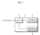
- a video processing apparatus 100 includes a first motion correcting part 10, a second motion correcting part 20, and a controller 30.
- the video processing apparatus 100 may be provided as a set-top box separated from a display module, but it may be provided in an integrated form in which a display part is included.
- the first motion correcting part 10 divides a video frame into blocks of a predetermined unit, and corrects a motion with respect to at least some area of the present frame by using a motion vector of an adjacent block adjacent to the present block.
- the first motion correcting part 10 performs an MJC algorithm for calculating a proper motion vector with respect to the present block on the basis of a motion vector obtained from eight blocks adjacent to the present block.
- the video processing apparatus 100 inputs a digital signal converted through an ADC (analog to digital converter) 11 into a frame buffer 12 if an analog signal is inputted.
- the frame buffer stores the inputted video signal.
- the digital signal is directly inputted into the frame buffer, and the MJC algorithm is performed in an MJC block 13 with respect to the video signal stored in the frame buffer.
- FIG. 2B is a drawing for illustrating the MJC algorithm.
- the MJC algorithm divides one frame into a predetermined size of blocks, and calculates a proper motion vector with the present block A on the basis of the motion vector obtained from the eight adjacent blocks (A') adjacent to the present block A to perform motion correction.
- the second motion correcting part 20 performs motion correction by using the motion vector of the adjacent frame adjacent to the present frame.
- the second motion correcting part 20 may generate a new frame with respect to an interlace signal on the basis of the present frame and the preceding frame prior to the present frame to perform an MAD algorithm for converting the new frame into a progressive signal.
- the second motion correcting part 20 performs a 3-D interlace with respect to a still image, and a 2-D interlace with respect to a video.
- the second motion correcting part 20 bypasses the input video signal by control of the controller 30 if the progressive signal is inputted.
- the first motion correcting part 10 and the second motion correcting part 20 estimate a motion vector with respect to a block of which the motion is to be estimated (hereinafter, referred to as "the present block") of the present frame and perform the motion correction according to the sum of an absolute difference (SAD) according to the result.
- the present block a block of which the motion is to be estimated
- the controller 30 controls the first motion correcting part 10 to correct the motion if the number of the adjacent blocks on which the video can be displayed among the adjacent blocks adjacent to the present block is not smaller than a predetermined value, and controls the second motion correcting part 20 to correct the motion if the number of the adjacent blocks on which the video can be displayed is smaller than the predetermined value.
- the controller 30 divides one frame into blocks in the size of 8 x 8, and calculates the number of blocks on which the video can be displayed with respect to eight blocks adjacent to the present block. Accordingly, if the number of the adjacent blocks on which the video can be displayed is three or five, for example, if the present block is located on the side edges of the screen, the controller 30 controls the second motion correcting part 20 to correct the motion by using the adjacent frame, and if the number of the adjacent blocks on which the video can be displayed is eight, the controller 30 controls the first motion correcting part 10 to correct the motion.
- the full-scan video for displaying the entire inputted video can be displayed without an error.
- the controller 30 may set the motion vector of the adjacent block as a zero vector, that is, zero (0,0) if the number of the adjacent blocks on which the video can be displayed is smaller than the predetermined value.
- FIG. 3 illustrates a process in which the controller 30 sets an area where the number of the adjacent blocks on which the video can be displayed is smaller than the predetermined value.
- the controller 30 controls the first motion correcting part 10 not to operate and controls the second motion correcting part 20 to perform motion correction, with respect to four areas of 3a, 3b, 3c and 3d.
- the controller 30 can control each size of the four areas 3a through 3d. Thus, errors which may be generated through the motion correction by the first motion correcting part 10 can be reduced.
- controller 30 may determine whether the first motion correcting part 10 will correct the motion or the second motion correcting part 20 will correct the motion with respect to the present block according to the motion of the object.
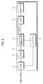
- FIG. 4 is a block diagram illustrating another exemplary embodiment of the video processing apparatus 101 according to the present invention.
- the video processing apparatus 101 may include a second motion correcting part 21, a controller 31, a tuner 40, a decoder 50, a scaler 60, and a display part 70.
- the tuner 40 receives a video signal having a frequency band corresponding to a predetermined channel selected by a user with respect to a broadcast video signal.
- the decoder 50 performs decoding for the received video signal according to a predetermined standard and extracts brightness information, color information, horizontal sync information, and vertical sync information, etc. of the video.
- the second motion correcting part 21 performs de-interlacing for converting the inputted interlace signal into a progressive signal, and may properly perform weaving and blending according to characteristics of the video.
- the scaler 60 performs video processing so that the video signal of which the motion has been corrected by the second motion correcting part 21 can be displayed in a proper size and position.
- the display part 70 displays a video on the basis of the signal processed by the scaler 60.
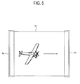
- the controller 30 (31) may control the second motion correcting part 20 (21) in place of the first motion correcting part 10 to correct the motion only with respect to an area 5a, that is, an area where the motion of the object begins if the object moves from left to right. That is because an area 5b where the motion of the object ends has no influence on the motion correction with respect to the block displayed on the screen even in the case that there is a lack of information on the adjacent blocks.
- controller 30 (31) may filter a border between the area where the first motion correcting part 10 corrects the motion and the area where the second motion correcting part 20 (21) corrects the motion so that the video can be naturally displayed.
- the controller 30 (31) may calculate the brightness of right-left pixels or up-down pixels of the border between the areas where the motion correction has been performed by the first motion correcting part 10 and the second motion correcting part 20 (21), calculate an average value of the calculated brightness, and set the brightness of the border pixels from the calculated average value, to thereby filter the border between the areas.
- FIG. 6 a video processing method according to the present invention will be described by referring to FIG. 6 .
- the controller 30 (31) calculates the number of adjacent blocks on which a video can be displayed, adjacent to the present block among blocks into which the video frame has been divided.
- the controller 30 (31) divides one frame into blocks in the size of 8 x 8, and calculates the number of the blocks on which the video can be displayed with respect to the eight blocks adjacent to the singular present block.
- the controller 30 (31) controls the first motion correcting part 10 to correct the motion with respect to at least some area of the present frame by using the motion vector of the adjacent blocks (S20).
- the controller 30 controls the second motion correcting part 20 (21) to correct the motion by using the motion vector of the frames adjacent to the present frame (S30).
- the motion is corrected by the MAD algorithm for generating a new frame on the basis of the present invention and the preceding frame prior to the present frame with respect to an interlace signal to convert the new frame into a progressive signal, and the second motion correcting part 20 (21) performs the 3-D interlace with respect to the still image and performs the 2-D interlace with respect to a video.
- the motion may be corrected with respect to the blocks corresponding to the side edges of the present frame.
- the motion may be corrected only with respect to blocks of one side edges where the motion of the object begins among the four side edges.
- the step S30 may further include performing filtering with respect to the border between the area where the motion correction is performed by using the motion vector of the adjacent blocks, that is, the area where the motion is corrected by the first motion correcting part 10 and the area where the motion is corrected by using the motion vector of the adjacent frame, that is, the area where the motion is corrected by the second motion correcting part 20 (21).
- the video processing apparatus and the video processing method according to exemplary embodiments of the present invention can perform motion correction with respect to areas with a small number of adjacent blocks by using an adjacent frame, to thereby display a video having an improved quality.
- the video processing apparatus and the video processing method according to exemplary embodiments of the present invention can control the size of an area where motion correction is performed by using an adjacent frame, to thereby efficiently process a video.
- the video processing apparatus and the video processing method according to exemplary embodiments of the present invention can filter a border between areas where motion correction is performed by different algorithms, to thereby naturally display the border.
- the video processing apparatus and the video processing method according to exemplary embodiments of the present invention can display an undistorted full-scan video.
Landscapes
- Engineering & Computer Science (AREA)
- Multimedia (AREA)
- Signal Processing (AREA)
- Television Systems (AREA)
- Controls And Circuits For Display Device (AREA)
Description
- The present invention relates to a video processing apparatus and a video processing method, and more particularly, to a video processing apparatus and method which performs motion correction for a video frame
- In general, a video processing apparatus performs video processing for a video signal to output a displayable video. The video processing apparatus performs video processing for a video signal including a predetermined video received from a broadcasting station, or a video signal inputted from various video devices such as a DVD.
- The video processing apparatus sequentially displays a plurality of unit videos included in the video signal, that is, a plurality of frames. However, since the video processing apparatus has a limited number of frames to display per unit time, in the case that a video includes an object with a quick movement, a user may not perceive the movement of the object to be natural. Accordingly, the conventional video processing apparatus performs a Frame Rate Conversion (FRC) for converting a frame rate, a Movie Judder Cancellation (MJC) for dividing a frame into a predetermined unit of blocks and estimating a motion by using a motion vector of an adjacent block adjacent to an arbitrary block, and so on, to display a corrected frame.
- However, a conventional video processing apparatus using the MJC algorithm has a problem in that motion correction cannot be accurately performed due to the lack of the number of adjacent blocks on side edges of a screen to cause a halo phenomenon around the object. To solve such a problem, the conventional video processing apparatus performs over-scanning so that side edges of a screen are not displayed, but there has been an increasing desire to watch full-scan video.
-
US2001/004385 A1 describes a motion vector detection system for detecting a motion vector for motion compensation in moving picture compression. - It is an aspect of the present invention to provide a video processing apparatus which can perform motion correction by using an adjacent frame with respect to an area having a small number of adjacent blocks to thereby display a video having an improved quality, and a video processing method thereof.
- Another aspect of the present invention is to provide a video processing apparatus which can control the size of an area where the motion correction is performed by using the adjacent frame to thereby efficiently process a video, and a video processing method thereof.
- Still another aspect of the present invention is to provide a video processing apparatus which can filter a border between the areas where the motion correction is performed by different algorithms to thereby naturally display the border between the areas where the motion correction is performed, and a video processing method thereof.
- Yet another aspect of the present invention is to provide a video processing apparatus which can display an undistorted full-scan video, and a video processing method thereof.
- Additional aspects of the present invention will be set forth in part in the description which follows and, in part, will be obvious from the description, or may be learned by practice of the present invention.
- The foregoing and/or other aspects of the present invention can be achieved by providing a video processing apparatus, including: a first motion correcting part which divides a video frame into blocks of a predetermined unit, and corrects a motion with respect to at least some area of a present frame by using a motion vector of an adjacent block adjacent to the present block; a second motion correcting part which corrects the motion by using a motion vector of an adjacent frame adjacent to the present frame; and a controller which controls the first motion correcting part to correct the motion if the number of the adjacent blocks on which a video can be displayed is not smaller than a predetermined value, and controls the second motion correcting part to correct the motion if the number of the adjacent blocks on which the video can be displayed is smaller than the predetermined value.
- The second motion correcting part may perform a Motion Adaptive De-interlace (MAD) to correct the motion.
- The controller may control to perform the motion correction with respect to a block corresponding to a side edge of the present frame.
- The controller may control the second motion correcting part to correct the motion only with respect to a block of one side edge where a motion of an object begins.
- The size of the block may be controlled.
- The controller may perform filtering with respect to a border between an area where the motion correction is performed by the first motion correcting part and an area where the motion correction is performed by the second motion correcting part.
- At least one of the first motion correcting part and the second motion correcting part may correct the motion by a difference of absolute values of pixels on the same position inside the block.
- The controller may determine whether or not the video can be displayed with respect to eight blocks adjacent to the present block.
- The video displayed by the motion correction may be provided as a full-scan video.
- The foregoing and/or other aspects of the present invention can be also achieved by providing a video processing method of a video processing apparatus, including: calculating the number of adjacent blocks on which a video can be displayed among blocks adjacent to a present block among blocks into which a video frame is divided; determining whether or not the number of the adjacent blocks on which the video can be displayed is smaller than a predetermined value; correcting a motion with respect to at least some area of a present frame by using a motion vector of the adjacent blocks if the number of the adjacent blocks on which the video can be displayed is not smaller than the predetermined value; and correcting the motion by using a motion vector of a frame adjacent to the present frame if the number of the adjacent blocks on which the video can be displayed is smaller than the predetermined value.
- In the correcting the motion, there may be performed an MAD with respect to the present block in which the number of the adjacent blocks is smaller than the predetermined value.
- In the correcting the motion, the motion may be corrected with respect to the block corresponding to the brink of the present frame.
- In the correcting the motion, the motion may be corrected only with respect to a block of one side edge where a motion of an object begins by using the motion vector of the adjacent frame.
- The size of the block may be controlled.
- The correcting the motion may include performing filtering with respect to a border between an area where the motion correction is performed by using the motion vector of the adjacent blocks and an area where the motion correction is performed by using the motion vector of the adjacent frame.
- In the correcting the motion, the motion may be corrected by a difference of absolute values of pixels on the same position inside the block.
- In the determining whether or not the number of the adjacent blocks on which the video can be displayed is smaller than the predetermined value, there may be determined whether or not the video can be displayed with respect to eight blocks adjacent to the present block.
- The video displayed by the motion correction may be provided as a full-scan video of an input video signal.
- The above and/or other aspects of the present invention will become apparent and more readily appreciated from the following description of exemplary embodiments, taken in conjunction with the accompanying drawings, in which:
-
FIGs. 1 and2A are block diagrams illustrating a video processing apparatus according to an exemplary embodiment of the present invention; -
FIG. 2B illustrates a process of performing motion correction in the video processing apparatus according to exemplary embodiments of the present invention; -
FIG. 3 is a block diagram illustrating a video processing apparatus according to another exemplary embodiment of the present invention; -
FIG. 4 illustrates an example in which the video processing apparatus according to exemplary embodiments of the present invention performs motion correction using adjacent blocks; -
FIG. 5 illustrates another example in which the video processing apparatus according to exemplary embodiments of the present invention performs motion correction using adjacent blocks; and -
FIG. 6 is a flow diagram illustrating a video processing method according to an exemplary embodiment of the present invention. - Reference will now be made in detail to exemplary embodiments of the present invention, examples of which are illustrated in the accompanying drawings, wherein like reference numerals refer to like elements throughout. The exemplary embodiments are described below so as to explain the present invention by referring to the figures.
- Referring to
FIG. 1 , avideo processing apparatus 100 includes a firstmotion correcting part 10, a secondmotion correcting part 20, and acontroller 30. Thevideo processing apparatus 100 may be provided as a set-top box separated from a display module, but it may be provided in an integrated form in which a display part is included. - The first
motion correcting part 10 divides a video frame into blocks of a predetermined unit, and corrects a motion with respect to at least some area of the present frame by using a motion vector of an adjacent block adjacent to the present block. The firstmotion correcting part 10 performs an MJC algorithm for calculating a proper motion vector with respect to the present block on the basis of a motion vector obtained from eight blocks adjacent to the present block. - As shown in
FIG. 2A , thevideo processing apparatus 100 according to the present invention inputs a digital signal converted through an ADC (analog to digital converter) 11 into aframe buffer 12 if an analog signal is inputted. The frame buffer stores the inputted video signal. The digital signal is directly inputted into the frame buffer, and the MJC algorithm is performed in anMJC block 13 with respect to the video signal stored in the frame buffer. -
FIG. 2B is a drawing for illustrating the MJC algorithm. The MJC algorithm divides one frame into a predetermined size of blocks, and calculates a proper motion vector with the present block A on the basis of the motion vector obtained from the eight adjacent blocks (A') adjacent to the present block A to perform motion correction. - The second
motion correcting part 20 performs motion correction by using the motion vector of the adjacent frame adjacent to the present frame. The secondmotion correcting part 20 may generate a new frame with respect to an interlace signal on the basis of the present frame and the preceding frame prior to the present frame to perform an MAD algorithm for converting the new frame into a progressive signal. The secondmotion correcting part 20 performs a 3-D interlace with respect to a still image, and a 2-D interlace with respect to a video. - Of course, since there is no need to perform the IPC (Interlace to Progressive Conversion) if the input signal is a progressive signal, the second
motion correcting part 20 bypasses the input video signal by control of thecontroller 30 if the progressive signal is inputted. - Here, the first
motion correcting part 10 and the secondmotion correcting part 20 estimate a motion vector with respect to a block of which the motion is to be estimated (hereinafter, referred to as "the present block") of the present frame and perform the motion correction according to the sum of an absolute difference (SAD) according to the result. - The
controller 30 controls the firstmotion correcting part 10 to correct the motion if the number of the adjacent blocks on which the video can be displayed among the adjacent blocks adjacent to the present block is not smaller than a predetermined value, and controls the secondmotion correcting part 20 to correct the motion if the number of the adjacent blocks on which the video can be displayed is smaller than the predetermined value. - The
controller 30 divides one frame into blocks in the size of 8 x 8, and calculates the number of blocks on which the video can be displayed with respect to eight blocks adjacent to the present block. Accordingly, if the number of the adjacent blocks on which the video can be displayed is three or five, for example, if the present block is located on the side edges of the screen, thecontroller 30 controls the secondmotion correcting part 20 to correct the motion by using the adjacent frame, and if the number of the adjacent blocks on which the video can be displayed is eight, thecontroller 30 controls the firstmotion correcting part 10 to correct the motion. Thus, the full-scan video for displaying the entire inputted video can be displayed without an error. - The
controller 30 may set the motion vector of the adjacent block as a zero vector, that is, zero (0,0) if the number of the adjacent blocks on which the video can be displayed is smaller than the predetermined value. -
FIG. 3 illustrates a process in which thecontroller 30 sets an area where the number of the adjacent blocks on which the video can be displayed is smaller than the predetermined value. As shown inFIG. 3 , thecontroller 30 controls the firstmotion correcting part 10 not to operate and controls the secondmotion correcting part 20 to perform motion correction, with respect to four areas of 3a, 3b, 3c and 3d. - Here, the
controller 30 can control each size of the fourareas 3a through 3d. Thus, errors which may be generated through the motion correction by the firstmotion correcting part 10 can be reduced. - Also, the
controller 30 may determine whether the firstmotion correcting part 10 will correct the motion or the secondmotion correcting part 20 will correct the motion with respect to the present block according to the motion of the object. -
FIG. 4 is a block diagram illustrating another exemplary embodiment of thevideo processing apparatus 101 according to the present invention. As shown inFIG. 4 , thevideo processing apparatus 101 may include a secondmotion correcting part 21, acontroller 31, atuner 40, adecoder 50, ascaler 60, and adisplay part 70. - The
tuner 40 receives a video signal having a frequency band corresponding to a predetermined channel selected by a user with respect to a broadcast video signal. - The
decoder 50 performs decoding for the received video signal according to a predetermined standard and extracts brightness information, color information, horizontal sync information, and vertical sync information, etc. of the video. - The second
motion correcting part 21 performs de-interlacing for converting the inputted interlace signal into a progressive signal, and may properly perform weaving and blending according to characteristics of the video. - The
scaler 60 performs video processing so that the video signal of which the motion has been corrected by the secondmotion correcting part 21 can be displayed in a proper size and position. - The
display part 70 displays a video on the basis of the signal processed by thescaler 60. - As shown in
FIG. 5 , the controller 30 (31) may control the second motion correcting part 20 (21) in place of the firstmotion correcting part 10 to correct the motion only with respect to anarea 5a, that is, an area where the motion of the object begins if the object moves from left to right. That is because anarea 5b where the motion of the object ends has no influence on the motion correction with respect to the block displayed on the screen even in the case that there is a lack of information on the adjacent blocks. - Meanwhile, the controller 30 (31) may filter a border between the area where the first
motion correcting part 10 corrects the motion and the area where the second motion correcting part 20 (21) corrects the motion so that the video can be naturally displayed. - In other words, the controller 30 (31) may calculate the brightness of right-left pixels or up-down pixels of the border between the areas where the motion correction has been performed by the first
motion correcting part 10 and the second motion correcting part 20 (21), calculate an average value of the calculated brightness, and set the brightness of the border pixels from the calculated average value, to thereby filter the border between the areas. - Hereinafter, a video processing method according to the present invention will be described by referring to
FIG. 6 . - First, the controller 30 (31) calculates the number of adjacent blocks on which a video can be displayed, adjacent to the present block among blocks into which the video frame has been divided. Here, the controller 30 (31) divides one frame into blocks in the size of 8 x 8, and calculates the number of the blocks on which the video can be displayed with respect to the eight blocks adjacent to the singular present block.
- Next, if the number of the adjacent blocks on which the video can be displayed is not smaller than the predetermined value (S10 - NO), the controller 30 (31) controls the first
motion correcting part 10 to correct the motion with respect to at least some area of the present frame by using the motion vector of the adjacent blocks (S20). - If the number of the adjacent blocks on which the video can be displayed is smaller than the predetermined value (S10 - YES), the
controller 30 controls the second motion correcting part 20 (21) to correct the motion by using the motion vector of the frames adjacent to the present frame (S30). - Here, the motion is corrected by the MAD algorithm for generating a new frame on the basis of the present invention and the preceding frame prior to the present frame with respect to an interlace signal to convert the new frame into a progressive signal, and the second motion correcting part 20 (21) performs the 3-D interlace with respect to the still image and performs the 2-D interlace with respect to a video.
- In addition, in the operation S30, the motion may be corrected with respect to the blocks corresponding to the side edges of the present frame. Here, the motion may be corrected only with respect to blocks of one side edges where the motion of the object begins among the four side edges.
- Also, the step S30 may further include performing filtering with respect to the border between the area where the motion correction is performed by using the motion vector of the adjacent blocks, that is, the area where the motion is corrected by the first
motion correcting part 10 and the area where the motion is corrected by using the motion vector of the adjacent frame, that is, the area where the motion is corrected by the second motion correcting part 20 (21). - As described above, the video processing apparatus and the video processing method according to exemplary embodiments of the present invention can perform motion correction with respect to areas with a small number of adjacent blocks by using an adjacent frame, to thereby display a video having an improved quality.
- Also, the video processing apparatus and the video processing method according to exemplary embodiments of the present invention can control the size of an area where motion correction is performed by using an adjacent frame, to thereby efficiently process a video.
- In addition, the video processing apparatus and the video processing method according to exemplary embodiments of the present invention can filter a border between areas where motion correction is performed by different algorithms, to thereby naturally display the border.
- Also, the video processing apparatus and the video processing method according to exemplary embodiments of the present invention can display an undistorted full-scan video.
- Although a few exemplary embodiments of the present invention have been shown and described, it will be appreciated by those skilled in the art that changes may be made in these exemplary embodiments without departing from the principles of the invention, the scope of which is defined in the appended claims.
Claims (15)
- A video processing apparatus, comprising:a first motion correcting part for correcting motion with respect to first areas of a present frame by using a motion vector of an adjacent block in the present frame which is adjacent to a respective present block of the present frame, wherein the present frame is divided into blocks of a predetermined unit; anda second motion correcting part for correcting motion with respect to second areas of the present frame by using a motion vector of an adjacent frame which is adjacent to the present frame; characterized in that it includesa controller for controlling the first motion correcting part to correct the motion with respect to the first areas of the present frame in which a number of adjacent blocks in the present frame is not smaller than eight, and for controlling the second motion correcting part to correct the motion with respect to the second areas of the present frame in which the number of adjacent blocks in the present frame is smaller than eight.
- The video processing apparatus according to claim 1, wherein the second motion correcting part is arranged to perform a Motion Adaptive De-interlace (MAD) to correct the motion.
- The video processing apparatus according to claim 1, wherein the controller is arranged to control the second motion correcting part to perform the motion correction with respect to a block corresponding to a side edge of the present frame.
- The video processing apparatus according to claim 3, wherein the controller is arranged to control the second motion correcting part to correct the motion only with respect to a block of one side edge where a motion of an object begins.
- The video processing apparatus according to claim 3 or 4, wherein a size of the blocks can be controlled.
- The video processing apparatus according to any one of the preceding claims, wherein the controller is arranged to perform filtering with respect to a border between the first areas where the motion correction is performed by the first motion correcting part and the second areas where the motion correction is performed by the second motion correcting part.
- The video processing apparatus according to any one of the preceding claims, wherein at least one of the first motion correcting part and the second motion correcting part is arranged to correct motion by a difference of absolute values of pixels on a same position inside the respective present block.
- The video processing apparatus according to any one of the preceding claims, wherein video displayed by the motion correction is provided as a full-scan video.
- A method of video processing, the method comprising:calculating a number of adjacent blocks in a present video frame, the present video frame being divided into blocks of a predetermined unit, the adjacent blocks being blocks that are adjacent to a respective present block in the present video frame;determining whether or not the number of adjacent blocks is smaller than eight;correcting respective motion with respect to first areas of a present frame associated with the respective present block by using a motion vector of the adjacent blocks if the number of adjacent blocks is not smaller than eight; andcorrecting motion with respect to second areas of the present frame by using a motion vector of a frame adjacent to the present frame if the number of adjacent blocks is smaller than eight.
- The video processing method according to claim 9, wherein correcting the motion with respect to the second areas of the present frame comprises performing a Motion Adaptive De-interlace (MAD) with respect to the respective present block in which the number of the adjacent blocks is smaller than eight.
- The video processing method according to claim 9, wherein in correcting the motion with respect to the second areas of the present frame, the motion is corrected with respect to a block corresponding to a side edge of the present frame.
- The video processing method according to claim 11, wherein in correcting the motion with respect to the second areas of the present frame, the motion is corrected only with respect to a block of one side edge where a motion of an object begins by using the motion vector of the adjacent frame.
- The video processing method according to any one of claims 9 to 12, wherein correcting the motion comprises performing filtering with respect to a border between the first areas where the motion correction is performed by using the motion vector of the adjacent blocks and the second areas where the motion correction is performed by using the motion vector of the adjacent frame.
- The video processing method according to any one of claims 9 to 13, wherein, the motion is corrected by a difference of absolute values of pixels on a same position inside the respective present block.
- The video processing method of any one of claims 9 to 14, comprising providing the video displayed by the motion correction as a full-scan video.
Applications Claiming Priority (1)
| Application Number | Priority Date | Filing Date | Title |
|---|---|---|---|
| KR1020070122234A KR101427115B1 (en) | 2007-11-28 | 2007-11-28 | Image processing apparatus and image processing method thereof |
Publications (2)
| Publication Number | Publication Date |
|---|---|
| EP2068552A1 EP2068552A1 (en) | 2009-06-10 |
| EP2068552B1 true EP2068552B1 (en) | 2013-04-17 |
Family
ID=40433919
Family Applications (1)
| Application Number | Title | Priority Date | Filing Date |
|---|---|---|---|
| EP08170014.8A Not-in-force EP2068552B1 (en) | 2007-11-28 | 2008-11-26 | Video processing apparatus and video processing method |
Country Status (3)
| Country | Link |
|---|---|
| US (1) | US8090154B2 (en) |
| EP (1) | EP2068552B1 (en) |
| KR (1) | KR101427115B1 (en) |
Families Citing this family (3)
| Publication number | Priority date | Publication date | Assignee | Title |
|---|---|---|---|---|
| US8395709B2 (en) * | 2009-03-04 | 2013-03-12 | ATI Technology ULC | 3D video processing |
| CN117041585A (en) | 2016-10-10 | 2023-11-10 | 三星电子株式会社 | Method and device for encoding or decoding coding units of picture contours |
| KR102664804B1 (en) * | 2018-10-10 | 2024-05-14 | 삼성디스플레이 주식회사 | Display apparatus and method of driving display panel using the same |
Family Cites Families (7)
| Publication number | Priority date | Publication date | Assignee | Title |
|---|---|---|---|---|
| CA2079434A1 (en) | 1991-09-30 | 1993-03-31 | Derek Andrew | Motion vector estimation, motion picture encoding and storage |
| EP1120976A4 (en) * | 1999-07-29 | 2006-03-29 | Mitsubishi Electric Corp | METHOD FOR DETECTING MOTION VECTOR |
| JP3690259B2 (en) * | 2000-09-27 | 2005-08-31 | 日本電気株式会社 | High-speed moving image encoding apparatus and high-speed moving image encoding method |
| KR100396558B1 (en) * | 2001-10-25 | 2003-09-02 | 삼성전자주식회사 | Apparatus and method for converting frame and/or field rate using adaptive motion compensation |
| KR100605746B1 (en) * | 2003-06-16 | 2006-07-31 | 삼성전자주식회사 | Block based motion compensation device and method |
| US7170561B2 (en) | 2003-12-04 | 2007-01-30 | Lsi Logic Corporation | Method and apparatus for video and image deinterlacing and format conversion |
| KR100586882B1 (en) | 2004-04-13 | 2006-06-08 | 삼성전자주식회사 | Coding Method and Apparatus Supporting Motion Scalability |
-
2007
- 2007-11-28 KR KR1020070122234A patent/KR101427115B1/en not_active Expired - Fee Related
-
2008
- 2008-07-28 US US12/180,833 patent/US8090154B2/en not_active Expired - Fee Related
- 2008-11-26 EP EP08170014.8A patent/EP2068552B1/en not_active Not-in-force
Also Published As
| Publication number | Publication date |
|---|---|
| US20090136151A1 (en) | 2009-05-28 |
| KR20090055353A (en) | 2009-06-02 |
| EP2068552A1 (en) | 2009-06-10 |
| US8090154B2 (en) | 2012-01-03 |
| KR101427115B1 (en) | 2014-08-08 |
Similar Documents
| Publication | Publication Date | Title |
|---|---|---|
| AU2003248047B2 (en) | Method and video processing unit for processing a video signal | |
| US8749703B2 (en) | Method and system for selecting interpolation as a means of trading off judder against interpolation artifacts | |
| US20080181312A1 (en) | Television receiver apparatus and a frame-rate converting method for the same | |
| US8355442B2 (en) | Method and system for automatically turning off motion compensation when motion vectors are inaccurate | |
| JP4119092B2 (en) | Method and apparatus for converting the number of frames of an image signal | |
| US8345148B2 (en) | Method and system for inverse telecine and scene change detection of progressive video | |
| US8154654B2 (en) | Frame interpolation device, frame interpolation method and image display device | |
| US20090153442A1 (en) | Plasma Display Apparatus | |
| EP2068552B1 (en) | Video processing apparatus and video processing method | |
| JP4762343B2 (en) | Image quality adjusting apparatus and image quality adjusting method | |
| JP3596521B2 (en) | Image signal processing apparatus and method | |
| JP2000259146A (en) | Image display device | |
| JP2001292341A (en) | Outline enhancement method and digital broadcast receiving apparatus | |
| KR101140442B1 (en) | Image status information correction | |
| KR101018563B1 (en) | Television receiver and image processing method | |
| JP5114274B2 (en) | Television receiver and frame rate conversion method thereof | |
| JP2010147699A (en) | Interpolation frame generating apparatus, interpolation frame generating method, and broadcast receiving apparatus | |
| US7466361B2 (en) | Method and system for supporting motion in a motion adaptive deinterlacer with 3:2 pulldown (MAD32) | |
| KR20080011026A (en) | Image processing apparatus and image processing method | |
| KR20110080371A (en) | Noise reduction method of digital TV | |
| RU123615U1 (en) | TELEVISION RECEIVER, IMAGE PROCESSING DEVICE WITH ADAPTIVE CORRECTION OF MOVING IMAGES BASED ON MOTION STREAM TECHNOLOGY | |
| KR100703165B1 (en) | Image processing apparatus and image processing method | |
| JP2010251897A (en) | Broadcast signal receiver, broadcast signal receiving method, and broadcast signal receiving program | |
| KR20130021127A (en) | Image processing apparatus and control method thereof | |
| JP2012010214A (en) | Image processing apparatus, and image processing method |
Legal Events
| Date | Code | Title | Description |
|---|---|---|---|
| PUAI | Public reference made under article 153(3) epc to a published international application that has entered the european phase |
Free format text: ORIGINAL CODE: 0009012 |
|
| AK | Designated contracting states |
Kind code of ref document: A1 Designated state(s): AT BE BG CH CY CZ DE DK EE ES FI FR GB GR HR HU IE IS IT LI LT LU LV MC MT NL NO PL PT RO SE SI SK TR |
|
| AX | Request for extension of the european patent |
Extension state: AL BA MK RS |
|
| 17P | Request for examination filed |
Effective date: 20091202 |
|
| AKX | Designation fees paid |
Designated state(s): DE GB NL |
|
| 17Q | First examination report despatched |
Effective date: 20110906 |
|
| RAP1 | Party data changed (applicant data changed or rights of an application transferred) |
Owner name: SAMSUNG ELECTRONICS CO., LTD. |
|
| GRAP | Despatch of communication of intention to grant a patent |
Free format text: ORIGINAL CODE: EPIDOSNIGR1 |
|
| RIN1 | Information on inventor provided before grant (corrected) |
Inventor name: CHO, HYEUNG-RAE |
|
| GRAS | Grant fee paid |
Free format text: ORIGINAL CODE: EPIDOSNIGR3 |
|
| GRAA | (expected) grant |
Free format text: ORIGINAL CODE: 0009210 |
|
| AK | Designated contracting states |
Kind code of ref document: B1 Designated state(s): DE GB NL |
|
| REG | Reference to a national code |
Ref country code: GB Ref legal event code: FG4D |
|
| REG | Reference to a national code |
Ref country code: DE Ref legal event code: R096 Ref document number: 602008023851 Country of ref document: DE Effective date: 20130613 |
|
| REG | Reference to a national code |
Ref country code: NL Ref legal event code: T3 |
|
| PLBE | No opposition filed within time limit |
Free format text: ORIGINAL CODE: 0009261 |
|
| STAA | Information on the status of an ep patent application or granted ep patent |
Free format text: STATUS: NO OPPOSITION FILED WITHIN TIME LIMIT |
|
| 26N | No opposition filed |
Effective date: 20140120 |
|
| REG | Reference to a national code |
Ref country code: DE Ref legal event code: R097 Ref document number: 602008023851 Country of ref document: DE Effective date: 20140120 |
|
| PGFP | Annual fee paid to national office [announced via postgrant information from national office to epo] |
Ref country code: DE Payment date: 20141021 Year of fee payment: 7 Ref country code: GB Payment date: 20141021 Year of fee payment: 7 |
|
| PGFP | Annual fee paid to national office [announced via postgrant information from national office to epo] |
Ref country code: NL Payment date: 20141021 Year of fee payment: 7 |
|
| REG | Reference to a national code |
Ref country code: DE Ref legal event code: R119 Ref document number: 602008023851 Country of ref document: DE |
|
| GBPC | Gb: european patent ceased through non-payment of renewal fee |
Effective date: 20151126 |
|
| REG | Reference to a national code |
Ref country code: NL Ref legal event code: MM Effective date: 20151201 |
|
| PG25 | Lapsed in a contracting state [announced via postgrant information from national office to epo] |
Ref country code: NL Free format text: LAPSE BECAUSE OF NON-PAYMENT OF DUE FEES Effective date: 20151201 |
|
| PG25 | Lapsed in a contracting state [announced via postgrant information from national office to epo] |
Ref country code: GB Free format text: LAPSE BECAUSE OF NON-PAYMENT OF DUE FEES Effective date: 20151126 Ref country code: DE Free format text: LAPSE BECAUSE OF NON-PAYMENT OF DUE FEES Effective date: 20160601 |