EP2068412A2 - System und Verfahren zur Sicherung eines Busbahngehäuses an Busbahn-Stromleiter - Google Patents
System und Verfahren zur Sicherung eines Busbahngehäuses an Busbahn-Stromleiter Download PDFInfo
- Publication number
- EP2068412A2 EP2068412A2 EP08170070A EP08170070A EP2068412A2 EP 2068412 A2 EP2068412 A2 EP 2068412A2 EP 08170070 A EP08170070 A EP 08170070A EP 08170070 A EP08170070 A EP 08170070A EP 2068412 A2 EP2068412 A2 EP 2068412A2
- Authority
- EP
- European Patent Office
- Prior art keywords
- flanges
- busway
- side plates
- slits
- power
- Prior art date
- Legal status (The legal status is an assumption and is not a legal conclusion. Google has not performed a legal analysis and makes no representation as to the accuracy of the status listed.)
- Withdrawn
Links
- 239000004020 conductor Substances 0.000 title claims abstract description 16
- 238000000034 method Methods 0.000 title claims abstract description 14
- CWYNVVGOOAEACU-UHFFFAOYSA-N Fe2+ Chemical compound [Fe+2] CWYNVVGOOAEACU-UHFFFAOYSA-N 0.000 claims abstract description 10
- 229910052751 metal Inorganic materials 0.000 claims abstract description 10
- 239000002184 metal Substances 0.000 claims abstract description 10
- 229910052782 aluminium Inorganic materials 0.000 claims description 7
- XAGFODPZIPBFFR-UHFFFAOYSA-N aluminium Chemical compound [Al] XAGFODPZIPBFFR-UHFFFAOYSA-N 0.000 claims description 7
- RYGMFSIKBFXOCR-UHFFFAOYSA-N Copper Chemical compound [Cu] RYGMFSIKBFXOCR-UHFFFAOYSA-N 0.000 claims description 3
- 229910052802 copper Inorganic materials 0.000 claims description 3
- 239000010949 copper Substances 0.000 claims description 3
- 239000012858 resilient material Substances 0.000 description 6
- 230000000295 complement effect Effects 0.000 description 5
- 229910000831 Steel Inorganic materials 0.000 description 4
- 239000010959 steel Substances 0.000 description 4
- 229910000838 Al alloy Inorganic materials 0.000 description 2
- 230000008646 thermal stress Effects 0.000 description 2
- 238000010276 construction Methods 0.000 description 1
- 238000002955 isolation Methods 0.000 description 1
- 239000000463 material Substances 0.000 description 1
- 238000012986 modification Methods 0.000 description 1
- 230000004048 modification Effects 0.000 description 1
- 230000007935 neutral effect Effects 0.000 description 1
- 230000005855 radiation Effects 0.000 description 1
- 230000002787 reinforcement Effects 0.000 description 1
- 238000001228 spectrum Methods 0.000 description 1
Images



Classifications
-
- H—ELECTRICITY
- H02—GENERATION; CONVERSION OR DISTRIBUTION OF ELECTRIC POWER
- H02G—INSTALLATION OF ELECTRIC CABLES OR LINES, OR OF COMBINED OPTICAL AND ELECTRIC CABLES OR LINES
- H02G5/00—Installations of bus-bars
- H02G5/04—Partially-enclosed installations, e.g. in ducts and adapted for sliding or rolling current collection
-
- H—ELECTRICITY
- H02—GENERATION; CONVERSION OR DISTRIBUTION OF ELECTRIC POWER
- H02G—INSTALLATION OF ELECTRIC CABLES OR LINES, OR OF COMBINED OPTICAL AND ELECTRIC CABLES OR LINES
- H02G5/00—Installations of bus-bars
- H02G5/06—Totally-enclosed installations, e.g. in metal casings
-
- H—ELECTRICITY
- H02—GENERATION; CONVERSION OR DISTRIBUTION OF ELECTRIC POWER
- H02G—INSTALLATION OF ELECTRIC CABLES OR LINES, OR OF COMBINED OPTICAL AND ELECTRIC CABLES OR LINES
- H02G3/00—Installations of electric cables or lines or protective tubing therefor in or on buildings, equivalent structures or vehicles
- H02G3/02—Details
-
- H—ELECTRICITY
- H02—GENERATION; CONVERSION OR DISTRIBUTION OF ELECTRIC POWER
- H02G—INSTALLATION OF ELECTRIC CABLES OR LINES, OR OF COMBINED OPTICAL AND ELECTRIC CABLES OR LINES
- H02G5/00—Installations of bus-bars
- H02G5/005—Laminated bus-bars
-
- H—ELECTRICITY
- H02—GENERATION; CONVERSION OR DISTRIBUTION OF ELECTRIC POWER
- H02G—INSTALLATION OF ELECTRIC CABLES OR LINES, OR OF COMBINED OPTICAL AND ELECTRIC CABLES OR LINES
- H02G5/00—Installations of bus-bars
- H02G5/02—Open installations
- H02G5/025—Supporting structures
Definitions
- the subject matter described herein relates generally to power busways and, more particularly, to securing a busway housing to busway power conductors.
- Power busways used within multi-phase electric power distribution systems generally consist of long, rectangular bars of copper or aluminum material. Each individual bar is electrically insulated to maintain electrical isolation between the individual phases as well as between the phase conductors and the neutral conductors. In accordance with electrical codes, a ground conductor must be associated within the busway power distribution system.
- U.S. Patent No. 4,804,804 entitled "Thermally Efficient Power Busway Housing” describes a two-piece extruded aluminum alloy housing shaped to provide support and ground conduction facility to power busway conductors described above.
- the two-piece housing is attached together with snap-fit connectors along its top and bottom surfaces.
- the housing is attached to the busway power conductors by means of insulated bolts.
- General Electric's Spectra TM Series Busway uses a unique double-insulated tie bolt to attach the aluminum housing to the busway power conductors.
- the tie bolts are inserted through the center of the busway providing predictable consistent strength and high short circuit rating.
- a power busway assembly comprises a pair of opposing non-ferrous metal apertured side plates.
- the side plates have a U-shaped configuration and intern comprise a pair of top and bottom flanges that are joined by a flat piece.
- the power busway assembly further comprises a means on one end of each of the flanges for interlocking the side plates together.
- the interlocking means intern comprises an angulated projection or an angulated slot.
- First rails extending from one of the pairs of flanges are also included that provide hanger support connection means.
- second rails extending from another one of the pairs of flanges are included that provide ground stab connection means.
- the power busway assembly further comprises at least one brace that is interconnected with the flanges. The brace is dimensioned and configured to bias the interlocking means together.
- a method of securing a busway housing to busway power conductors comprises using a plurality of braces.
- the busway housing comprises a pair of opposing non-ferrous metal apertured side plates.
- the side plates have a U-shaped configuration and intern comprise a pair of top and bottom flanges that are joined by a flat piece.
- the top and bottom flanges comprise slits
- the plurality of braces comprises a hooked end and a flanged end.
- the method comprises inserting the hooked end into one of the slits, and rotating the brace until the flanged end is adjacent to another of the slits.
- the method further comprises providing an axial force to the flanged end, wherein the force is perpendicular to the side plates, and whereby the flanged end completely engages the another of the slits.
- FIG. 1 is a perspective view of a busway housing unit for supporting the bus bar power conductors.
- FIG. 2 is a perspective view of a brace in accordance with one embodiment of the present invention.
- FIG. 2A is a bottom view of the brace shown in FIG. 2 .
- FIG. 2B is a side view of the brace shown in FIG. 2 .
- FIG. 3 is a cross-sectional view along line 3-3 in FIG. 1 of the busway housing unit of FIG. 1 including a plurality of the braces of FIG. 2 .
- FIG. 4 is a perspective view of a bracket according to another aspect of the present invention.
- FIG. 4A is a side view of the bracket shown in FIG. 4 .
- FIG. 4B is an end view of a portion of the bracket shown in FIG. 4 showing a flange and a catch.
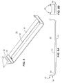
- FIG. 5 is a perspective view of a bracket according to a further aspect of the present invention.
- FIG. 5A is a side view of the bracket shown in FIG. 5 .
- FIG. 5B is an end view of a portion of the bracket shown in FIG. 5 showing a flange and a catch.
- FIG. 6 is a view similar to that of FIG. 3 including a plurality of brackets.
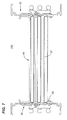
- FIG. 7 is a view similar to that of FIG. 6 including bus bar power conductors.
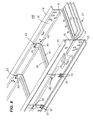
- FIG. 8 is an enlarged, partial perspective view of a power busway assembly shown in FIG. 7 .
- An embodiment of the present invention concerns a system and method for securing a power busway assembly that reduces the need for the use of fasteners, employs fewer components, yet still provides predictable consistent strength and high short circuit rating.
- FIG. 1 A prior art busway housing unit is shown generally at 10 in FIG. 1 .
- Housing unit 10 comprises a side plate or side piece 11 positioned opposite a complementary side plate or side piece 12.
- Side plates 11, 12 each are illustrated as having a U-shaped configuration, may include apertures (not shown) and comprise a non-ferrous metal, such as, an aluminum alloy that greatly increases the tensile strength of the aluminum without substantially deterring from the good electrical and thermal properties.
- the aluminum side plates 11, 12, which form busway housing 10 create a complete 360° high level ground path for ground faults and serves as a continuous bond between busway sections, fittings and bus plugs (not shown).
- Both aluminum side plates 11, 12 are provided with a top flange 13, 15 and a bottom flange 14, 16.
- Top flange 13 and bottom flange 14 extend perpendicularly from flat piece 8 on side plate 11.
- top flange 15 and bottom flange 16 extend perpendicularly from flat piece 9 on side plate 12.
- Rails 19, 20 extend perpendicularly from top flanges 13, 15.
- rails 20 extend perpendicularly from bottom flanges 14, 16 as indicated.
- One pair of rails 19 or 20 can provide hanger support connection means while the other pair of rails can provide ground stab connection means.
- Rails 19, 20 in addition to flanges 13-16 provide added structural support to busway housing unit 10 and increased surface area to side plates 11, 12 for improved thermal radiation to the surrounding air.
- Angulated slot 17 extends along one edge of top flange 13 on side plate 11 to receive a complementary angulated projection 18, which extends along top flange 15 on opposing side plate 12.
- a similar angulated slot 17' extends along bottom flange 16 of side plate 12 to receive a similar angulated projection 18', which extends along bottom flange 14 of side plate 11.
- Angulated slots 17, 17' and angulated projection 18, 18' provide interlocking means, which secure side plates 11 and 12 together.
- bus bars Three or four busway or bus bar power conductors 27, hereafter “bus bars", are attached to busway housing unit 10. Each bus bar 27 represents a separate phase of a three-phase power distribution system. Bus bars 27 are secured to busway housing unit 10 with a plurality of braces 30 (not shown).
- Brace 30 comprises cuffed segment 31, hooked end 32, and flanged end 33. Brace 30 is approximately 1.5" wide and 0.125" in thickness. The length of brace 30 may vary according to the dimensions of busway housing unit 10.
- brace 30 comprises a rigid and resilient material such as steel, which provides important mechanical properties such as strength and durability. These mechanical properties are desirable, for example, when a busway is exposed to dynamic and thermal stresses as a result of a short circuit. Because brace 30 is located outside of busway housing 10, brace 30 has no influence on the electrical properties of the busway.
- FIG. 3 illustrates a cross-section of an assembled busway housing unit 100 that includes a plurality of braces 30.
- Cuffed segment 31 is offset from flat segment 34 and accommodates the interlocking means of flanges 13-16. Specifically, angulated slots 17 and 17' fit directly inside cuffed segment 31, thus biasing the interlocking means of flanges 13-16.
- flat segment 34 sits directly on flanges 13 and 15.
- flat segment 34 sits directly on flanges 14 and 16.
- brace 30 may be interconnected with flanges 13, 15 and 14, 16 through slits 22 and 23.
- Hooked end 32 fits inside complementary slit 22, located on flanges 13 and 14.
- flanged end 33 fits inside complementary slit 23, located on flanges 15 and 16.
- Slit 22 on flange 13 is located directly parallel to slit 22 on flange 14.
- slit 23 on flange 15 is located directly parallel to slit 23 on flange 16.
- slits 22 and 23 are located along identical and regular intervals along the length of side plates 11 and 12, respectively, on approximately 12" centers. The area of each slit 22 is dimensioned to receive hooked end 32 of brace 30.
- each slit 23 is dimensioned to receive flanged end 33 of brace 30.
- hooked end 32 is inserted into slit 22. Then, a rotational force is applied to brace 30 until flanged end 33 is adjacent to complementary slit 23.
- An axial force perpendicular to side plates 11, 12 is applied to flanged end 33. The rotational force coupled with the axial force allows flanged end 33 to completely engage slit 23 and secures brace 30 into position.
- FIG. 4 shows a top view of a bracket 40 in accordance with another aspect of the invention.
- Bracket 40 comprises base 41 and a pair of flanges 44.
- Base 41 includes rib 42, which is a curved stiffening portion that runs longitudinally along the center of base 41.
- Flanges 44 extend perpendicularly from base 41 and comprise angled segment 43 and catch 45.
- Base 51 includes rib 52, which may be similar to rib 42.
- Flanges 54 also extend perpendicularly from base 51 and comprise angled segment 53 and catch 55.
- Brackets 40, 50 are approximately 2.5" wide and 0.1" in thickness.
- the length of brackets 40, 50 are equal and may vary according to the dimensions of busway housing unit 10. More particularly, the length of bases 41, 51 may vary according to lengths of flat pieces 9 and 8, respectively. Furthermore, the distance between catches 45 and 55 is equal.
- Brackets 40 and 50 are comprised of a rigid and resilient material such as steel, which provides important mechanical properties such as strength and durability. These properties are desirable, for example, when a busway is exposed to dynamic and thermal stresses as a result of a short circuit. Because brackets 40 and 50 are located outside of busway housing 10, brackets 40 and 50 have no influence on the electrical properties of the busway.
- FIG. 6 illustrates the assembled busway housing unit 100 of FIG. 3 including a plurality of brackets 40, 50.
- Brackets 40, 50 are dimensioned and configured to further secure busway system 100 by providing supplementary reinforcement to braces 30.
- Base 41 of bracket 40 runs traversely along flat piece 9 on side plate 12 ( FIG. 8 ).
- Rib 42 stiffens base 41 against flat piece 9 in order to prevent bracket 40 from lifting off side plate 12.
- Angled segments 43 curve away from side plate 12. Angled segments 43 distribute the forces from bracket 40 onto side plate 12 for a more secure busway system 100. In addition, angled segments 43 allow bracket 40 to apply an opposing force to flanges 15, 16 to reduce wear on flanges 15, 16 and brace 30.
- bracket 40 may be interconnected with each of flanges 15 and 16 through slits 23.
- Catch 45 hooks onto slits 23 discussed above.
- the width of slits 23 is at least equal to the width of bracket 40.
- the length between catches 45 is at least equal to the width of brace 30. This ensures that catches 45 and either flanged end 33 of brace 30 can both fit inside slot 23 at the same time.
- bracket 50 provides similar structure and functionality to side plate 11 that bracket 40 provides to side plate 12.
Landscapes
- Engineering & Computer Science (AREA)
- Architecture (AREA)
- Civil Engineering (AREA)
- Structural Engineering (AREA)
- Installation Of Bus-Bars (AREA)
Applications Claiming Priority (1)
| Application Number | Priority Date | Filing Date | Title |
|---|---|---|---|
| US11/950,940 US20090145625A1 (en) | 2007-12-05 | 2007-12-05 | System and Method for Securing a Busway Housing to Busway Power Conductors |
Publications (1)
| Publication Number | Publication Date |
|---|---|
| EP2068412A2 true EP2068412A2 (de) | 2009-06-10 |
Family
ID=40373718
Family Applications (1)
| Application Number | Title | Priority Date | Filing Date |
|---|---|---|---|
| EP08170070A Withdrawn EP2068412A2 (de) | 2007-12-05 | 2008-11-27 | System und Verfahren zur Sicherung eines Busbahngehäuses an Busbahn-Stromleiter |
Country Status (8)
| Country | Link |
|---|---|
| US (1) | US20090145625A1 (de) |
| EP (1) | EP2068412A2 (de) |
| JP (1) | JP2009142148A (de) |
| KR (1) | KR20090059057A (de) |
| CN (1) | CN101453107A (de) |
| AU (1) | AU2008246263A1 (de) |
| CA (1) | CA2644248A1 (de) |
| MX (1) | MX2008015482A (de) |
Cited By (2)
| Publication number | Priority date | Publication date | Assignee | Title |
|---|---|---|---|---|
| US8576082B2 (en) | 2010-07-15 | 2013-11-05 | Jones Group Forensic Engineers | Busway joint parameter detection system |
| EP3151353A1 (de) * | 2015-09-29 | 2017-04-05 | EAE Elektrik Asansör Endüstrisi Insaat Sanayi ve Ticaret Anonim Sirketi | Ein einrast gehäuse für ein stromschiene |
Families Citing this family (17)
| Publication number | Priority date | Publication date | Assignee | Title |
|---|---|---|---|---|
| US7819676B1 (en) * | 2009-11-12 | 2010-10-26 | Power Distribution Inc. | Electrical power distribution system |
| KR100986678B1 (ko) * | 2009-11-30 | 2010-10-08 | 주식회사 광명전기 | 플러그 인 부스 덕트 |
| US8847088B2 (en) | 2011-09-22 | 2014-09-30 | General Electric Company | Cover mounted handle operating mechanism with integrated interlock assembly for a busplug enclosure |
| KR101225249B1 (ko) * | 2011-10-17 | 2013-01-22 | 대한전선 주식회사 | 부스덕트용 덕트 구조 |
| JP6082547B2 (ja) * | 2012-09-04 | 2017-02-15 | 株式会社アテックス | バスバーインサート樹脂成形品の製造方法 |
| CN102868127A (zh) * | 2012-09-11 | 2013-01-09 | 江苏华强电力设备有限公司 | 新型的母线槽侧板 |
| US9281674B2 (en) | 2012-11-01 | 2016-03-08 | Schneider Electric USA, Inc. | Method of busway construction |
| CN104269798A (zh) * | 2014-09-20 | 2015-01-07 | 常州市武进庙桥南方锻造有限公司 | 防盗式母线槽 |
| CN107785844A (zh) * | 2016-08-27 | 2018-03-09 | 江苏德驰电气有限公司 | 一种大电流空气绝缘母线槽 |
| CN107546696A (zh) * | 2017-10-18 | 2018-01-05 | 江苏瑞仁汽车部件有限公司 | 密集型母线槽 |
| CN108167529B (zh) * | 2018-02-05 | 2023-12-19 | 徐工集团工程机械股份有限公司 | 一种工程机械用多功能管线路悬挂固定系统 |
| CN111490509A (zh) * | 2020-04-28 | 2020-08-04 | 镇江市美盛母线有限公司 | 一种新型密集型母线槽壳体结构 |
| CN111490508A (zh) * | 2020-04-28 | 2020-08-04 | 镇江市美盛母线有限公司 | 一种便捷安装密集型母线槽 |
| CN112234556B (zh) * | 2020-11-20 | 2022-02-08 | 吉林大洋电气科技有限公司 | 一种电力母线加工用母线槽固定设备 |
| US11824336B2 (en) * | 2021-10-21 | 2023-11-21 | Siemens Industry, Inc. | Outdoor busway system having protected conductor sections |
| CN114725867B (zh) * | 2022-03-24 | 2024-09-20 | 国网浙江省电力有限公司桐庐县供电公司 | 方便装配的母线槽 |
| CN118867925A (zh) * | 2024-09-23 | 2024-10-29 | 浙江桥架母线有限公司 | 一种母线槽用防蚀保护装置 |
Citations (1)
| Publication number | Priority date | Publication date | Assignee | Title |
|---|---|---|---|---|
| US4804804A (en) | 1987-11-19 | 1989-02-14 | General Electric Company | Thermally efficient power busway housing |
Family Cites Families (2)
| Publication number | Priority date | Publication date | Assignee | Title |
|---|---|---|---|---|
| US4950841A (en) * | 1989-05-30 | 1990-08-21 | General Electric Company | Thermally efficient splice joint for electrical distribution busway |
| US6180885B1 (en) * | 1997-01-17 | 2001-01-30 | General Electric Company | Weatherproofing busway systems |
-
2007
- 2007-12-05 US US11/950,940 patent/US20090145625A1/en not_active Abandoned
-
2008
- 2008-11-20 AU AU2008246263A patent/AU2008246263A1/en not_active Abandoned
- 2008-11-20 CA CA002644248A patent/CA2644248A1/en not_active Abandoned
- 2008-11-27 EP EP08170070A patent/EP2068412A2/de not_active Withdrawn
- 2008-12-02 JP JP2008306922A patent/JP2009142148A/ja not_active Withdrawn
- 2008-12-04 MX MX2008015482A patent/MX2008015482A/es not_active Application Discontinuation
- 2008-12-04 KR KR1020080122525A patent/KR20090059057A/ko not_active Withdrawn
- 2008-12-05 CN CNA2008101798121A patent/CN101453107A/zh active Pending
Patent Citations (1)
| Publication number | Priority date | Publication date | Assignee | Title |
|---|---|---|---|---|
| US4804804A (en) | 1987-11-19 | 1989-02-14 | General Electric Company | Thermally efficient power busway housing |
Cited By (2)
| Publication number | Priority date | Publication date | Assignee | Title |
|---|---|---|---|---|
| US8576082B2 (en) | 2010-07-15 | 2013-11-05 | Jones Group Forensic Engineers | Busway joint parameter detection system |
| EP3151353A1 (de) * | 2015-09-29 | 2017-04-05 | EAE Elektrik Asansör Endüstrisi Insaat Sanayi ve Ticaret Anonim Sirketi | Ein einrast gehäuse für ein stromschiene |
Also Published As
| Publication number | Publication date |
|---|---|
| KR20090059057A (ko) | 2009-06-10 |
| AU2008246263A1 (en) | 2009-07-02 |
| MX2008015482A (es) | 2009-11-26 |
| JP2009142148A (ja) | 2009-06-25 |
| US20090145625A1 (en) | 2009-06-11 |
| CA2644248A1 (en) | 2009-06-05 |
| CN101453107A (zh) | 2009-06-10 |
Similar Documents
| Publication | Publication Date | Title |
|---|---|---|
| EP2068412A2 (de) | System und Verfahren zur Sicherung eines Busbahngehäuses an Busbahn-Stromleiter | |
| US4804804A (en) | Thermally efficient power busway housing | |
| CN107017472B (zh) | 具有自调节支架的电力汇流通道接头 | |
| US9590405B1 (en) | Busway joint coupling having an adjustable assembly for joining two busway sections | |
| US6039584A (en) | Electrical power distribution system | |
| CN106953217B (zh) | 具有叠层支撑系统的电力汇流通道接头 | |
| US6781818B2 (en) | Bus brace comb assembly | |
| CN107017536B (zh) | 具有叉形汇流条的可调节式电力汇流通道接头 | |
| US8163998B2 (en) | Electrical busway flange end stub | |
| US4886468A (en) | Insulated electrical power distribution busway tabs | |
| US20170201081A1 (en) | Electrical busway joint with external vise braces | |
| EP2806517B1 (de) | Sammelschiene für Stromverteilung | |
| AU584362B2 (en) | Electrical distribution system with an improved housing | |
| US5828006A (en) | Busway system with wedge brace supports | |
| US10522991B2 (en) | Compact busway for low and medium voltage | |
| WO2017147256A1 (en) | Splice plate assembly for cable tray | |
| CN103682998A (zh) | 用于汇流排支撑的模块化绝缘体及装配方法 | |
| CN101485058B (zh) | 用于母线的绝缘元件以及包括该元件的用于母线的绝缘支撑设备 | |
| MX2014002516A (es) | Sistema y metodo para porporcionar puntos de acceso discretos en un conducto para barra colectora. | |
| JPS59501441A (ja) | レ−ル支持体上に導体レ−ルを固定するためのレ−ル絶縁体 | |
| CN1879281B (zh) | 包括接地导体的长定子和装有所述定子的磁悬浮铁路 | |
| US20060121796A1 (en) | Electric phase bus bar | |
| EP0319483A2 (de) | Modulare elektrische Niederspannungsschalttafel für ein modulares elektrisches Gerät | |
| EP3866287B1 (de) | Isolierend sammelschienenhalter eines schaltschranks | |
| CA1316996C (en) | Insulated electrical power distribution busway tabs |
Legal Events
| Date | Code | Title | Description |
|---|---|---|---|
| PUAI | Public reference made under article 153(3) epc to a published international application that has entered the european phase |
Free format text: ORIGINAL CODE: 0009012 |
|
| AK | Designated contracting states |
Kind code of ref document: A2 Designated state(s): AT BE BG CH CY CZ DE DK EE ES FI FR GB GR HR HU IE IS IT LI LT LU LV MC MT NL NO PL PT RO SE SI SK TR |
|
| AX | Request for extension of the european patent |
Extension state: AL BA MK RS |
|
| STAA | Information on the status of an ep patent application or granted ep patent |
Free format text: STATUS: THE APPLICATION IS DEEMED TO BE WITHDRAWN |
|
| 18D | Application deemed to be withdrawn |
Effective date: 20110531 |