EP2068404A2 - Deckel mit Stecker für eine Deckel-Offen-Erkennung - Google Patents
Deckel mit Stecker für eine Deckel-Offen-Erkennung Download PDFInfo
- Publication number
- EP2068404A2 EP2068404A2 EP08105791A EP08105791A EP2068404A2 EP 2068404 A2 EP2068404 A2 EP 2068404A2 EP 08105791 A EP08105791 A EP 08105791A EP 08105791 A EP08105791 A EP 08105791A EP 2068404 A2 EP2068404 A2 EP 2068404A2
- Authority
- EP
- European Patent Office
- Prior art keywords
- housing part
- plug
- cover
- receptacle
- edge
- Prior art date
- Legal status (The legal status is an assumption and is not a legal conclusion. Google has not performed a legal analysis and makes no representation as to the accuracy of the status listed.)
- Granted
Links
- 238000003780 insertion Methods 0.000 claims abstract description 6
- 230000037431 insertion Effects 0.000 claims abstract description 6
- 230000013011 mating Effects 0.000 claims abstract description 4
- 238000001514 detection method Methods 0.000 description 3
- 239000000463 material Substances 0.000 description 1
- 238000012544 monitoring process Methods 0.000 description 1
Images
Classifications
-
- H—ELECTRICITY
- H05—ELECTRIC TECHNIQUES NOT OTHERWISE PROVIDED FOR
- H05K—PRINTED CIRCUITS; CASINGS OR CONSTRUCTIONAL DETAILS OF ELECTRIC APPARATUS; MANUFACTURE OF ASSEMBLAGES OF ELECTRICAL COMPONENTS
- H05K5/00—Casings, cabinets or drawers for electric apparatus
- H05K5/02—Details
- H05K5/0247—Electrical details of casings, e.g. terminals, passages for cables or wiring
-
- H—ELECTRICITY
- H01—ELECTRIC ELEMENTS
- H01R—ELECTRICALLY-CONDUCTIVE CONNECTIONS; STRUCTURAL ASSOCIATIONS OF A PLURALITY OF MUTUALLY-INSULATED ELECTRICAL CONNECTING ELEMENTS; COUPLING DEVICES; CURRENT COLLECTORS
- H01R13/00—Details of coupling devices of the kinds covered by groups H01R12/70 or H01R24/00 - H01R33/00
- H01R13/40—Securing contact members in or to a base or case; Insulating of contact members
- H01R13/405—Securing in non-demountable manner, e.g. moulding, riveting
- H01R13/41—Securing in non-demountable manner, e.g. moulding, riveting by frictional grip in grommet, panel or base
-
- H—ELECTRICITY
- H01—ELECTRIC ELEMENTS
- H01R—ELECTRICALLY-CONDUCTIVE CONNECTIONS; STRUCTURAL ASSOCIATIONS OF A PLURALITY OF MUTUALLY-INSULATED ELECTRICAL CONNECTING ELEMENTS; COUPLING DEVICES; CURRENT COLLECTORS
- H01R31/00—Coupling parts supported only by co-operation with counterpart
- H01R31/08—Short-circuiting members for bridging contacts in a counterpart
-
- H—ELECTRICITY
- H01—ELECTRIC ELEMENTS
- H01R—ELECTRICALLY-CONDUCTIVE CONNECTIONS; STRUCTURAL ASSOCIATIONS OF A PLURALITY OF MUTUALLY-INSULATED ELECTRICAL CONNECTING ELEMENTS; COUPLING DEVICES; CURRENT COLLECTORS
- H01R13/00—Details of coupling devices of the kinds covered by groups H01R12/70 or H01R24/00 - H01R33/00
- H01R13/46—Bases; Cases
- H01R13/52—Dustproof, splashproof, drip-proof, waterproof, or flameproof cases
- H01R13/5213—Covers
-
- H—ELECTRICITY
- H01—ELECTRIC ELEMENTS
- H01R—ELECTRICALLY-CONDUCTIVE CONNECTIONS; STRUCTURAL ASSOCIATIONS OF A PLURALITY OF MUTUALLY-INSULATED ELECTRICAL CONNECTING ELEMENTS; COUPLING DEVICES; CURRENT COLLECTORS
- H01R13/00—Details of coupling devices of the kinds covered by groups H01R12/70 or H01R24/00 - H01R33/00
- H01R13/66—Structural association with built-in electrical component
- H01R13/70—Structural association with built-in electrical component with built-in switch
- H01R13/701—Structural association with built-in electrical component with built-in switch the switch being actuated by an accessory, e.g. cover, locking member
Definitions
- the invention is based on a cover for attachment to a housing part according to the preamble of patent claim 1.
- Such a lid is for example by the DE 199 13 146 A1 known.
- a plug is set to unspecified manner, which cooperates with a mating connector of the housing.
- plugs in particular plugs for a cover-open detection, are fastened to the cover by standard connecting elements (eg screws).
- plastic cover 1 is used to close a housing opening of a housing (not shown).
- an electrical plug 2 is fastened to the housing cover 1 on the inside, which contacts an electrical mating plug of the housing and closes a monitoring circuit only when the cover 1 closes the housing opening. In this way, an open lid or a non-closed housing opening is detected.
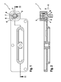
- the plug 2 is inserted into a receptacle 3 of the lid 1 and held therein by the plastically deformed edge 4 of the receptacle 3, which engages over the plug 2 against its insertion 5 .
- the edge 4 of the receptacle 3 has four plastically deformed Verstemmnasen 6 , which overlap the plug 2 against its insertion 5 and position it in the lid 1 and fix captive.
- the caulking lugs 6 are provided at an angular distance of 90 ° and lie in pairs opposite each other with respect to the receptacle 3.
- the plug 2 when the plug 2 is inserted into the receptacle 3, pressed with a four-armed stamp on the edge 4 of the receptacle 3, are formed by caulk or plastic deformation of housing material radially into the receptacle 3 into the Verstemmnasen 6.
- the stamp can be pressed off or force controlled.
- the stamp impressions (ie depressions) in the cover 1 are in Fig. 1 shown by dashed lines and designated 7 .
Landscapes
- Engineering & Computer Science (AREA)
- Microelectronics & Electronic Packaging (AREA)
- Connector Housings Or Holding Contact Members (AREA)
Abstract
Description
- Die Erfindung geht aus von einem Deckel zur Befestigung an einem Gehäuseteil nach der Gattung des Patentanspruchs 1.
- Ein solcher Deckel ist beispielsweise durch die
DE 199 13 146 A1 bekannt geworden. An diesem bekannten Deckel ist auf nicht näher beschriebene Weise ein Stecker festgelegt, der mit einem Gegenstecker des Gehäuses zusammenwirkt. Üblicherweise werden Stecker, insbesondere Stecker für eine Deckel-Offen-Erkennung, durch Standardverbindungselemente (z.B. Schrauben) am Deckel befestigt. - Erfindungsgemäß wird vorgeschlagen, den in eine Aufnahme des Gehäuseteils eingesteckten Stecker darin durch plastische Verformung des Rands der Aufnahme zu positionieren und unverlierbar zu fixieren. Diese unverlierbare Verbindung stellt eine kostengünstige Lösung dar und ermöglicht hohe Abzugskräfte
- Weitere Vorteile und vorteilhafte Ausgestaltungen des Gegenstands der Erfindung sind der Beschreibung, der Zeichnung und den Ansprüchen entnehmbar.
- Ein Ausführungsbeispiel des erfindungsgemäßen Gehäuseteils ist in der Zeichnung dargestellt und in der nachfolgenden Beschreibung näher erläutert. Die in den Figuren gezeigten Merkmale sind rein schematisch und nicht maßstäblich zu verstehen. Es zeigt:
- Fig. 1
- die Unterseite eines als Deckel ausgeführten erfindungsgemäßen Gehäuseteils mit einem daran befestigten elektrischen Stecker für eine Deckel-offen-Erkennung, und
- Fig. 2
- einen Längsschnitt des Deckels gemäß II-II in
Fig. 1 . - Der in
Fign. 1 und 2 gezeigte Deckel 1 aus Kunststoff dient zum Verschließen einer Gehäuseöffnung eines Gehäuses (nicht gezeigt). Für eine Deckel-Offen-Erkennung ist am Gehäusedeckel 1 innenseitig ein elektrischer Stecker 2 befestigt, der nur dann, wenn der Deckel 1 die Gehäuseöffnung verschließt, einen elektrischen Gegenstecker des Gehäuses kontaktiert und einen Überwachungsstromkreis schließt. Auf diese Weise wird ein offener Deckel bzw. eine nicht verschlossene Gehäuseöffnung erkannt. - Der Stecker 2 ist in eine Aufnahme 3 des Deckels 1 eingesteckt und darin durch den plastisch verformten Rand 4 der Aufnahme 3, der den Stecker 2 entgegen seiner Einsteckrichtung 5 übergreift, gehalten. Der Rand 4 der Aufnahme 3 weist vier plastisch verformte Verstemmnasen 6 auf, die den Stecker 2 entgegen seiner Einsteckrichtung 5 übergreifen und so im Deckel 1 positionieren und unverlierbar fixieren. Die Verstemmnasen 6 sind im Winkelabstand von jeweils 90° vorgesehen und liegen jeweils paarweise einander bezüglich der Aufnahme 3 gegenüber.
- Genauer gesagt wird, wenn der Stecker 2 in die Aufnahme 3 eingesteckt ist, mit einem vierarmigen Stempel auf den Rand 4 der Aufnahme 3 gedrückt, bis durch Verstemmen bzw. plastisches Verformen von Gehäusematerial radial in die Aufnahme 3 hinein die Verstemmnasen 6 ausgebildet sind. Das Drücken des Stempels kann weg- oder kraftgesteuert erfolgen. Die Stempelabdrücke (d.h. Vertiefungen) im Deckel 1 sind in
Fig. 1 gestrichelt dargestellt und mit 7 bezeichnet.
Claims (6)
- Gehäuseteil (1), insbesondere Deckel, zur Befestigung an einem anderen Gehäuseteil, mit einem am Gehäuseteil (1) befestigten elektrischen Stecker (2) zum Kontaktieren eines elektrischen Gegensteckers am anderen Gehäuseteil,
dadurch gekennzeichnet,
dass der Stecker (2) in eine Aufnahme (3) des Gehäuseteils (1) eingesteckt ist und darin durch einen den Stecker (2) entgegen seiner Einsteckrichtung (5) übergreifenden, plastisch verformten Rand (4) der Aufnahme (3) gehalten ist. - Gehäuseteil nach Anspruch 1, dadurch gekennzeichnet, dass der Rand (4) der Aufnahme (3) mindestens eine plastisch verformte Verstemmnase (6) aufweist, die den Stecker (2) entgegen seiner Einsteckrichtung (5) übergreift.
- Gehäuseteil nach Anspruch 2, dadurch gekennzeichnet, dass der Rand (4) der Aufnahme (3) mindestens zwei Verstemmnasen (6) aufweist, die den Stecker (2) entgegen seiner Einsteckrichtung (5) übergreifen.
- Gehäuseteil nach Anspruch 3, dadurch gekennzeichnet, dass die mindestens zwei Verstemmnasen (6) bezüglich der Aufnahme (3) einander gegenüberliegen.
- Gehäuseteil nach Anspruch 3 oder 4, dadurch gekennzeichnet, dass die Verstemmnasen (6) jeweils in gleichem Winkelabstand zueinander vorgesehen sind.
- Gehäuseteil nach einem der vorhergehenden Ansprüche, dadurch gekennzeichnet, dass das Gehäuseteil (1) aus Kunststoff gebildet ist.
Applications Claiming Priority (1)
| Application Number | Priority Date | Filing Date | Title |
|---|---|---|---|
| DE200720016957 DE202007016957U1 (de) | 2007-12-05 | 2007-12-05 | Deckel mit Stecker für eine Deckel-Offen-Erkennung |
Publications (3)
| Publication Number | Publication Date |
|---|---|
| EP2068404A2 true EP2068404A2 (de) | 2009-06-10 |
| EP2068404A3 EP2068404A3 (de) | 2013-09-25 |
| EP2068404B1 EP2068404B1 (de) | 2014-11-05 |
Family
ID=39105822
Family Applications (1)
| Application Number | Title | Priority Date | Filing Date |
|---|---|---|---|
| EP20080105791 Ceased EP2068404B1 (de) | 2007-12-05 | 2008-11-13 | Deckel mit Stecker für eine Deckel-Offen-Erkennung |
Country Status (2)
| Country | Link |
|---|---|
| EP (1) | EP2068404B1 (de) |
| DE (1) | DE202007016957U1 (de) |
Citations (1)
| Publication number | Priority date | Publication date | Assignee | Title |
|---|---|---|---|---|
| DE19913146A1 (de) | 1999-03-23 | 2000-10-12 | Bosch Gmbh Robert | Elektronisches Steuergerät |
Family Cites Families (3)
| Publication number | Priority date | Publication date | Assignee | Title |
|---|---|---|---|---|
| US4430524A (en) * | 1982-03-22 | 1984-02-07 | Donald Santucci | Bridging clip cover |
| JP3292293B2 (ja) * | 1997-10-21 | 2002-06-17 | 矢崎総業株式会社 | スイッチ付きコネクタ装置 |
| JP2002352926A (ja) * | 2001-05-23 | 2002-12-06 | Sumitomo Wiring Syst Ltd | ジョイントコネクタ |
-
2007
- 2007-12-05 DE DE200720016957 patent/DE202007016957U1/de not_active Expired - Lifetime
-
2008
- 2008-11-13 EP EP20080105791 patent/EP2068404B1/de not_active Ceased
Patent Citations (1)
| Publication number | Priority date | Publication date | Assignee | Title |
|---|---|---|---|---|
| DE19913146A1 (de) | 1999-03-23 | 2000-10-12 | Bosch Gmbh Robert | Elektronisches Steuergerät |
Also Published As
| Publication number | Publication date |
|---|---|
| EP2068404A3 (de) | 2013-09-25 |
| EP2068404B1 (de) | 2014-11-05 |
| DE202007016957U1 (de) | 2008-02-21 |
Similar Documents
| Publication | Publication Date | Title |
|---|---|---|
| EP2301115B1 (de) | Elektrische anschlussvorrichtung | |
| EP2614695B1 (de) | Schaltungsgehäuse mit einer darin über positionierelemente positionierten leiterplatte | |
| DE102011079446A1 (de) | Sensoreinrichtung, insbesondere für die Verwendung in einem Kraftfahrzeug | |
| DE202014106058U1 (de) | Steckverbinder | |
| DE102015110070A1 (de) | Elektrische Verbindungsanordnung | |
| WO2015078460A1 (de) | Elektronische baugruppe mit einem gehäuse aus einem kunststoffteil und einem metallteil | |
| DE102018219651A1 (de) | Elektronisches Steuergerät | |
| EP1658626B1 (de) | Schaltgerät mit leiteranschluss mittels ringkabelschuh | |
| DE202013012658U1 (de) | Steckerbrücke zum Herstellen eines Steckers | |
| EP2223389B1 (de) | Vorrichtung und verfahren zur verliersicheren aufnahme einer schraube an einer anschlussklemme | |
| EP2766977B1 (de) | Stellantrieb | |
| EP3483996B1 (de) | Anordnung für eine kabeldurchführung | |
| EP3819138B1 (de) | Einbaueinheit | |
| AT523021A1 (de) | Elektrischer Steckverbinder | |
| EP2068404B1 (de) | Deckel mit Stecker für eine Deckel-Offen-Erkennung | |
| EP2200125B1 (de) | Geschirmter Steckverbinder | |
| DE102008040504A1 (de) | Elektrische Schaltungsanordnung | |
| DE102007058041A1 (de) | Anschlussflansch, insbesondere für eine elektrische Anschlussklemme | |
| DE102005022399B4 (de) | Vorrichtung zur Befestigung für einen mindestens einen Sensor aufweisenden Schaltungsträger | |
| EP2677614B1 (de) | Gehäuse zur Aufnahme eines Anhängermoduls | |
| DE102006036097B3 (de) | Steckverbinder, Anordnung mit Steckverbinder und Verfahren zur Montage | |
| DE102014000231A1 (de) | Clipmutter, Befestigungsanordnung und Verfahren zum Herstellen einer Clipmutter | |
| DE202020105230U1 (de) | Abdichtung und Flanschdichtungsvorrichtung | |
| EP3304651B1 (de) | Elektrischer steckverbinder | |
| DE102019120159A1 (de) | Verbinder |
Legal Events
| Date | Code | Title | Description |
|---|---|---|---|
| PUAI | Public reference made under article 153(3) epc to a published international application that has entered the european phase |
Free format text: ORIGINAL CODE: 0009012 |
|
| AK | Designated contracting states |
Kind code of ref document: A2 Designated state(s): AT BE BG CH CY CZ DE DK EE ES FI FR GB GR HR HU IE IS IT LI LT LU LV MC MT NL NO PL PT RO SE SI SK TR |
|
| AX | Request for extension of the european patent |
Extension state: AL BA MK RS |
|
| PUAL | Search report despatched |
Free format text: ORIGINAL CODE: 0009013 |
|
| AK | Designated contracting states |
Kind code of ref document: A3 Designated state(s): AT BE BG CH CY CZ DE DK EE ES FI FR GB GR HR HU IE IS IT LI LT LU LV MC MT NL NO PL PT RO SE SI SK TR |
|
| AX | Request for extension of the european patent |
Extension state: AL BA MK RS |
|
| RIC1 | Information provided on ipc code assigned before grant |
Ipc: H01R 31/08 20060101ALI20130822BHEP Ipc: H01R 13/641 20060101AFI20130822BHEP Ipc: H01R 13/41 20060101ALI20130822BHEP |
|
| 17P | Request for examination filed |
Effective date: 20140325 |
|
| RBV | Designated contracting states (corrected) |
Designated state(s): AT BE BG CH CY CZ DE DK EE ES FI FR GB GR HR HU IE IS IT LI LT LU LV MC MT NL NO PL PT RO SE SI SK TR |
|
| AKX | Designation fees paid |
Designated state(s): DE FR IT |
|
| GRAP | Despatch of communication of intention to grant a patent |
Free format text: ORIGINAL CODE: EPIDOSNIGR1 |
|
| RIC1 | Information provided on ipc code assigned before grant |
Ipc: H01R 13/641 20060101AFI20140522BHEP Ipc: H01R 13/41 20060101ALI20140522BHEP Ipc: H01R 31/08 20060101ALI20140522BHEP Ipc: H05K 5/02 20060101ALI20140522BHEP |
|
| INTG | Intention to grant announced |
Effective date: 20140606 |
|
| GRAS | Grant fee paid |
Free format text: ORIGINAL CODE: EPIDOSNIGR3 |
|
| GRAA | (expected) grant |
Free format text: ORIGINAL CODE: 0009210 |
|
| DAX | Request for extension of the european patent (deleted) | ||
| AK | Designated contracting states |
Kind code of ref document: B1 Designated state(s): DE FR IT |
|
| DAX | Request for extension of the european patent (deleted) | ||
| REG | Reference to a national code |
Ref country code: DE Ref legal event code: R096 Ref document number: 502008012371 Country of ref document: DE Effective date: 20141218 |
|
| REG | Reference to a national code |
Ref country code: DE Ref legal event code: R097 Ref document number: 502008012371 Country of ref document: DE |
|
| PLBE | No opposition filed within time limit |
Free format text: ORIGINAL CODE: 0009261 |
|
| STAA | Information on the status of an ep patent application or granted ep patent |
Free format text: STATUS: NO OPPOSITION FILED WITHIN TIME LIMIT |
|
| 26N | No opposition filed |
Effective date: 20150806 |
|
| REG | Reference to a national code |
Ref country code: FR Ref legal event code: PLFP Year of fee payment: 8 |
|
| REG | Reference to a national code |
Ref country code: FR Ref legal event code: PLFP Year of fee payment: 9 |
|
| PGFP | Annual fee paid to national office [announced via postgrant information from national office to epo] |
Ref country code: DE Payment date: 20170126 Year of fee payment: 9 |
|
| REG | Reference to a national code |
Ref country code: FR Ref legal event code: PLFP Year of fee payment: 10 |
|
| PGFP | Annual fee paid to national office [announced via postgrant information from national office to epo] |
Ref country code: FR Payment date: 20171124 Year of fee payment: 10 |
|
| PGFP | Annual fee paid to national office [announced via postgrant information from national office to epo] |
Ref country code: IT Payment date: 20171122 Year of fee payment: 10 |
|
| REG | Reference to a national code |
Ref country code: DE Ref legal event code: R119 Ref document number: 502008012371 Country of ref document: DE |
|
| PG25 | Lapsed in a contracting state [announced via postgrant information from national office to epo] |
Ref country code: DE Free format text: LAPSE BECAUSE OF NON-PAYMENT OF DUE FEES Effective date: 20180602 |
|
| PG25 | Lapsed in a contracting state [announced via postgrant information from national office to epo] |
Ref country code: IT Free format text: LAPSE BECAUSE OF NON-PAYMENT OF DUE FEES Effective date: 20181113 Ref country code: FR Free format text: LAPSE BECAUSE OF NON-PAYMENT OF DUE FEES Effective date: 20181130 |