EP2068383A1 - Accumulator - Google Patents
Accumulator Download PDFInfo
- Publication number
- EP2068383A1 EP2068383A1 EP08752101A EP08752101A EP2068383A1 EP 2068383 A1 EP2068383 A1 EP 2068383A1 EP 08752101 A EP08752101 A EP 08752101A EP 08752101 A EP08752101 A EP 08752101A EP 2068383 A1 EP2068383 A1 EP 2068383A1
- Authority
- EP
- European Patent Office
- Prior art keywords
- electric power
- power storage
- housing portion
- gas
- storage apparatus
- Prior art date
- Legal status (The legal status is an assumption and is not a legal conclusion. Google has not performed a legal analysis and makes no representation as to the accuracy of the status listed.)
- Granted
Links
Images




Classifications
-
- H—ELECTRICITY
- H01—ELECTRIC ELEMENTS
- H01G—CAPACITORS; CAPACITORS, RECTIFIERS, DETECTORS, SWITCHING DEVICES, LIGHT-SENSITIVE OR TEMPERATURE-SENSITIVE DEVICES OF THE ELECTROLYTIC TYPE
- H01G9/00—Electrolytic capacitors, rectifiers, detectors, switching devices, light-sensitive or temperature-sensitive devices; Processes of their manufacture
- H01G9/0003—Protection against electric or thermal overload; cooling arrangements; means for avoiding the formation of cathode films
-
- H—ELECTRICITY
- H01—ELECTRIC ELEMENTS
- H01G—CAPACITORS; CAPACITORS, RECTIFIERS, DETECTORS, SWITCHING DEVICES, LIGHT-SENSITIVE OR TEMPERATURE-SENSITIVE DEVICES OF THE ELECTROLYTIC TYPE
- H01G11/00—Hybrid capacitors, i.e. capacitors having different positive and negative electrodes; Electric double-layer [EDL] capacitors; Processes for the manufacture thereof or of parts thereof
- H01G11/14—Arrangements or processes for adjusting or protecting hybrid or EDL capacitors
- H01G11/18—Arrangements or processes for adjusting or protecting hybrid or EDL capacitors against thermal overloads, e.g. heating, cooling or ventilating
-
- H—ELECTRICITY
- H01—ELECTRIC ELEMENTS
- H01G—CAPACITORS; CAPACITORS, RECTIFIERS, DETECTORS, SWITCHING DEVICES, LIGHT-SENSITIVE OR TEMPERATURE-SENSITIVE DEVICES OF THE ELECTROLYTIC TYPE
- H01G11/00—Hybrid capacitors, i.e. capacitors having different positive and negative electrodes; Electric double-layer [EDL] capacitors; Processes for the manufacture thereof or of parts thereof
- H01G11/78—Cases; Housings; Encapsulations; Mountings
-
- H—ELECTRICITY
- H01—ELECTRIC ELEMENTS
- H01M—PROCESSES OR MEANS, e.g. BATTERIES, FOR THE DIRECT CONVERSION OF CHEMICAL ENERGY INTO ELECTRICAL ENERGY
- H01M10/00—Secondary cells; Manufacture thereof
- H01M10/60—Heating or cooling; Temperature control
- H01M10/61—Types of temperature control
- H01M10/613—Cooling or keeping cold
-
- H—ELECTRICITY
- H01—ELECTRIC ELEMENTS
- H01M—PROCESSES OR MEANS, e.g. BATTERIES, FOR THE DIRECT CONVERSION OF CHEMICAL ENERGY INTO ELECTRICAL ENERGY
- H01M10/00—Secondary cells; Manufacture thereof
- H01M10/60—Heating or cooling; Temperature control
- H01M10/62—Heating or cooling; Temperature control specially adapted for specific applications
- H01M10/625—Vehicles
-
- H—ELECTRICITY
- H01—ELECTRIC ELEMENTS
- H01M—PROCESSES OR MEANS, e.g. BATTERIES, FOR THE DIRECT CONVERSION OF CHEMICAL ENERGY INTO ELECTRICAL ENERGY
- H01M10/00—Secondary cells; Manufacture thereof
- H01M10/60—Heating or cooling; Temperature control
- H01M10/65—Means for temperature control structurally associated with the cells
- H01M10/655—Solid structures for heat exchange or heat conduction
- H01M10/6551—Surfaces specially adapted for heat dissipation or radiation, e.g. fins or coatings
-
- H—ELECTRICITY
- H01—ELECTRIC ELEMENTS
- H01M—PROCESSES OR MEANS, e.g. BATTERIES, FOR THE DIRECT CONVERSION OF CHEMICAL ENERGY INTO ELECTRICAL ENERGY
- H01M10/00—Secondary cells; Manufacture thereof
- H01M10/60—Heating or cooling; Temperature control
- H01M10/65—Means for temperature control structurally associated with the cells
- H01M10/656—Means for temperature control structurally associated with the cells characterised by the type of heat-exchange fluid
- H01M10/6567—Liquids
-
- H—ELECTRICITY
- H01—ELECTRIC ELEMENTS
- H01M—PROCESSES OR MEANS, e.g. BATTERIES, FOR THE DIRECT CONVERSION OF CHEMICAL ENERGY INTO ELECTRICAL ENERGY
- H01M50/00—Constructional details or processes of manufacture of the non-active parts of electrochemical cells other than fuel cells, e.g. hybrid cells
- H01M50/20—Mountings; Secondary casings or frames; Racks, modules or packs; Suspension devices; Shock absorbers; Transport or carrying devices; Holders
- H01M50/204—Racks, modules or packs for multiple batteries or multiple cells
-
- H—ELECTRICITY
- H01—ELECTRIC ELEMENTS
- H01M—PROCESSES OR MEANS, e.g. BATTERIES, FOR THE DIRECT CONVERSION OF CHEMICAL ENERGY INTO ELECTRICAL ENERGY
- H01M50/00—Constructional details or processes of manufacture of the non-active parts of electrochemical cells other than fuel cells, e.g. hybrid cells
- H01M50/20—Mountings; Secondary casings or frames; Racks, modules or packs; Suspension devices; Shock absorbers; Transport or carrying devices; Holders
- H01M50/271—Lids or covers for the racks or secondary casings
-
- H—ELECTRICITY
- H01—ELECTRIC ELEMENTS
- H01M—PROCESSES OR MEANS, e.g. BATTERIES, FOR THE DIRECT CONVERSION OF CHEMICAL ENERGY INTO ELECTRICAL ENERGY
- H01M50/00—Constructional details or processes of manufacture of the non-active parts of electrochemical cells other than fuel cells, e.g. hybrid cells
- H01M50/30—Arrangements for facilitating escape of gases
- H01M50/342—Non-re-sealable arrangements
- H01M50/3425—Non-re-sealable arrangements in the form of rupturable membranes or weakened parts, e.g. pierced with the aid of a sharp member
-
- H—ELECTRICITY
- H01—ELECTRIC ELEMENTS
- H01G—CAPACITORS; CAPACITORS, RECTIFIERS, DETECTORS, SWITCHING DEVICES, LIGHT-SENSITIVE OR TEMPERATURE-SENSITIVE DEVICES OF THE ELECTROLYTIC TYPE
- H01G11/00—Hybrid capacitors, i.e. capacitors having different positive and negative electrodes; Electric double-layer [EDL] capacitors; Processes for the manufacture thereof or of parts thereof
- H01G11/10—Multiple hybrid or EDL capacitors, e.g. arrays or modules
- H01G11/12—Stacked hybrid or EDL capacitors
-
- H—ELECTRICITY
- H01—ELECTRIC ELEMENTS
- H01G—CAPACITORS; CAPACITORS, RECTIFIERS, DETECTORS, SWITCHING DEVICES, LIGHT-SENSITIVE OR TEMPERATURE-SENSITIVE DEVICES OF THE ELECTROLYTIC TYPE
- H01G9/00—Electrolytic capacitors, rectifiers, detectors, switching devices, light-sensitive or temperature-sensitive devices; Processes of their manufacture
- H01G9/004—Details
- H01G9/08—Housing; Encapsulation
- H01G9/12—Vents or other means allowing expansion
-
- H—ELECTRICITY
- H01—ELECTRIC ELEMENTS
- H01M—PROCESSES OR MEANS, e.g. BATTERIES, FOR THE DIRECT CONVERSION OF CHEMICAL ENERGY INTO ELECTRICAL ENERGY
- H01M2200/00—Safety devices for primary or secondary batteries
-
- Y—GENERAL TAGGING OF NEW TECHNOLOGICAL DEVELOPMENTS; GENERAL TAGGING OF CROSS-SECTIONAL TECHNOLOGIES SPANNING OVER SEVERAL SECTIONS OF THE IPC; TECHNICAL SUBJECTS COVERED BY FORMER USPC CROSS-REFERENCE ART COLLECTIONS [XRACs] AND DIGESTS
- Y02—TECHNOLOGIES OR APPLICATIONS FOR MITIGATION OR ADAPTATION AGAINST CLIMATE CHANGE
- Y02E—REDUCTION OF GREENHOUSE GAS [GHG] EMISSIONS, RELATED TO ENERGY GENERATION, TRANSMISSION OR DISTRIBUTION
- Y02E60/00—Enabling technologies; Technologies with a potential or indirect contribution to GHG emissions mitigation
- Y02E60/10—Energy storage using batteries
-
- Y—GENERAL TAGGING OF NEW TECHNOLOGICAL DEVELOPMENTS; GENERAL TAGGING OF CROSS-SECTIONAL TECHNOLOGIES SPANNING OVER SEVERAL SECTIONS OF THE IPC; TECHNICAL SUBJECTS COVERED BY FORMER USPC CROSS-REFERENCE ART COLLECTIONS [XRACs] AND DIGESTS
- Y02—TECHNOLOGIES OR APPLICATIONS FOR MITIGATION OR ADAPTATION AGAINST CLIMATE CHANGE
- Y02E—REDUCTION OF GREENHOUSE GAS [GHG] EMISSIONS, RELATED TO ENERGY GENERATION, TRANSMISSION OR DISTRIBUTION
- Y02E60/00—Enabling technologies; Technologies with a potential or indirect contribution to GHG emissions mitigation
- Y02E60/13—Energy storage using capacitors
-
- Y—GENERAL TAGGING OF NEW TECHNOLOGICAL DEVELOPMENTS; GENERAL TAGGING OF CROSS-SECTIONAL TECHNOLOGIES SPANNING OVER SEVERAL SECTIONS OF THE IPC; TECHNICAL SUBJECTS COVERED BY FORMER USPC CROSS-REFERENCE ART COLLECTIONS [XRACs] AND DIGESTS
- Y02—TECHNOLOGIES OR APPLICATIONS FOR MITIGATION OR ADAPTATION AGAINST CLIMATE CHANGE
- Y02T—CLIMATE CHANGE MITIGATION TECHNOLOGIES RELATED TO TRANSPORTATION
- Y02T10/00—Road transport of goods or passengers
- Y02T10/60—Other road transportation technologies with climate change mitigation effect
- Y02T10/70—Energy storage systems for electromobility, e.g. batteries
Definitions
- the present invention provides a electric power storage apparatus including a housing, a partition which is placed in the housing to form a first housing portion and a second housing portion, a electric power storage unit which is housed in the first housing portion, a coolant which is housed in the first housing portion and is provided for cooling the electric power storage unit, and a pressure release means for releasing an internal pressure of the first housing portion to the second housing portion in an abnormal state of the electric power storage unit (a gas release state) in which gas is produced in the electric power storage unit.
- the pressure release valve and the gas release hole portion may be placed on different axes.
- the pressure release means includes a holding portion for holding the partition.
- the partition is detached at the holding portion due to an increased internal pressure of the first housing portion in the abnormal state of the electric power storage unit.
- the second housing portion may include a gas release hole portion for releasing the gas flowing from the first housing portion.
- the electric power storage unit has a gas release valve formed therein for releasing the gas.
- the internal pressure value of the first housing portion when the pressure release means release the pressure is equal to the internal pressure value of the electric power storage unit when the gas release valve releases the gas.
- the electric power storage unit may be a set of electric power storage elements includingapluralityof electric power storage elements connected in series or in parallel.
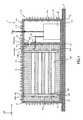
- Fig. 1 is a section view showing a electric power storage apparatus before a battery abnormality occurs.
- Fig. 2 is a section view showing a cylindrical unit cell.
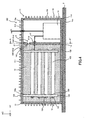
- Fig. 3 is a section view showing the electric power storage apparatus when a battery abnormality occurs.
- the battery housing portion 111 is filled with a coolant 13 for cooling the assembled battery 12.
- the partition 11d is provided with a rupture-type valve (pressure release means, pressure release valve) 14 for releasing an internal pressure of the battery housing portion 111 to the pressure release chamber 112 in a battery abnormality state (abnormality state of the electric power storage unit).
- the electric-device housing case 11 consists of an upper case 11a and a container body 11g.
- the container body 11g is formed of a side wall portion 11b and a bottom wall portion 11c which are integrally formed.
- the upper case 11a is formed separately from the container body 11g.
- the electric-device housing case 11 is made of metal material such as stainless steal having a high thermal conductivity, for example.
- the rupture-type valve 14 is formed of a through-hole portion 141 which extends through the partition 11d to connect the battery housing portion 111 to the pressure release chamber 112 and a close plate 142 which closes the through-hole portion 141 to prevent the coolant 13 from flowing into the pressure release chamber 112.
- the partition 11d and the bottom wall portion 11c may be formed separately and then joined together by a bonding means such as welding.
- the through-hole portion 141 is formed of a smaller through-hole portion 141a closer to the pressure release chamber 112 and a larger through-hole portion 141b closer to the battery housing portion 111 and having a diameter larger than that of the smaller through-hole portion 141a.
- the close plate 142 is fixed to an end face of the larger through-hole portion 141b closer to the pressure release chamber 112 (end face in a Y-axis direction). The fixing of the close plate 142 can be performed by a known method such as welding and sticking with an adhesive.
- the close plate 142 has a mechanical strength set such that the close plate 142 is broken at a pressure value lower than the upper limit of resistance to pressure of the battery housing portion 111. In Embodiment 1, the close plate 142 is broken when the internal pressure value of the battery housing portion 111 reaches 1 Mpa.
- the coolant 13 flows from the battery housing portion 111 into the pressure release chamber 112 and comes into contact with the J/B unit 16.
- the J/B unit 16 is unusable as well as the assembled battery 12 in the battery abnormality state, which eliminates the need for waterproofing or the like of the J/B unit 16.
- the electric device herein mentioned includes not only the J/B unit 16 but also another electric device (for example, a battery ECU which monitors an amount of charge and discharge of the assembled battery 12) connected electrically to the assembled battery 12.
- another electric device for example, a battery ECU which monitors an amount of charge and discharge of the assembled battery 12
- the support plate 123 for the assembled battery 12 has a screw hole portion 123a formed therein in a penetrating shape extending in the vertical direction.
- a fastening bolt 125 is inserted into each of the screw hole portions 123a through the upper case 11a from the outside of the electric-device housing case 11.
- the end portion of the fastening bolt 125 protrudes from the lower surface of the support plate 123, and a fastening nut 126 is tightened at the end portion of the fastening bolt 125.
- the assembled battery 12 and the upper case 11a can be unitized into one.
- the coolant 13 with a higher heat conductivity than cooling gas is used as a cooling medium for the assembled battery 12.
- Suitable materials of the coolant 13 filled in the battery housing portion 111 include one that has a high specific heat, a high thermal conductivity, and a high boiling point, causes no corrosion of the electric-device housing case 11 or the assembled battery 12, and has resistance to thermal decomposition, air oxidation, electrolysis or the like.
- the electrode element 135 is formed by spirally winding a strip-shaped positive electrode element 135b having a positive electrode active material applied to both surface thereof and a strip-shaped negative electrode element 135c having a negative electrode active material applied to both surface thereof with a separator 135a interposed between them.
- Examples of the positive electrode active material may include LiCoO 2 , LiNiO 2 , LiFeO 2 , LiCuO 2 , LiMnO 2 , LiMo 2 (M represents at least two of transition elements selected from the group consisting of Co, Ni, Fe, Cu, and Mn), and LiMn 2 O 4 , all of which are lithium-transition element compound oxides.
- the negative electrode active material is not particularly limited as long as it may electrochemically occlude and emit lithium ions. Specific examples thereof may include natural graphite, artificial graphite, coke, organic burned body, and metal chalcogenides.
- a disc-shaped current collecting plate 136 is welded to each end of the electrode element 135 in a longitudinal direction (Y direction) of the battery.
- the current collecting plate 136 may be made of aluminum foil, stainless steel fail, or copper foil, for example.
- the current collecting plates 136 are electrically and mechanically connected through conducting wires 137 to holding plates 139 which hold the electrodes 131 and 132.
- the rupture-type valve 139a When gas is produced in the electrode element 135 and causes the internal pressure of the battery outer can 134 to reach the upper limit of pressure (for example, 1 MPa), the rupture-type valve 139a is broken and lets out the gas to the outside of the cylindrical unit cell 122.
- the upper limit of pressure for example, 1 MPa
- the behavior of the electric power storage apparatus 1 will be described when the assembled battery 12 is overcharged with reference to Figs. 1 and 3 .
- the electrolyte contained in the cylindrical unit cell 122 is electrolyzed to produce gas which increases the internal pressure of the battery outer can 134.
- the rupture-type valve 139a is broken. The breakage of the rupture-type valve 139a causes the gas to be released into the coolant 13 to increase the internal pressure of the battery housing portion 111.
- the internal pressure of the battery housing portion 111 immediately reaches 1 Mpa to break the close plate 142 as shown in Fig. 3 .
- the coolant 13 contained in the battery housing portion 111 is ejected into the pressure release chamber 112 through the through-hole portion 141 in a horizontal direction.
- the coolant 13 ejected into the pressure release chamber 112 strikes the side wall portion 11b of the electric-device housing case 11 and then falls and is stored at the bottom of the pressure release chamber 112.
- the coolant 13 and the gas are partially moved to the pressure release chamber 112 in the battery abnormality state to enable prevention of an increased internal pressure of the battery housing portion 111. Consequently, it is possible to reduce the thickness of the electric-device housing case 11 and the size of the fastening member for connecting the upper case 11a and the container body 11d, so that the electric power storage apparatus 1 can be reduced in size and weight.
- Fig. 4 is a section view showing a electric power storage apparatus 101 shown in Fig. 5 taken along a B-B' line.
- Fig. 5 shows a rupture-type valve 14 projected onto a side wall portion 11b.
- the side wall portion 11b of a pressure release chamber 112 has a gas release hole portion 41 formed therein to release gas, which has flowed from a battery housing portion 111 into the pressure release chamber 112, to the outside of the electric power storage apparatus 101 in a battery abnormality state.
- a rupture-type valve 14 and the gas release hole portion 41 are placed on different axes which extend in a thickness direction (direction in parallel with a Y-axis direction) of a partition 11d.
- the gas release hole portion 41 be formed above the liquid level of a coolant 13 flowing into the pressure release chamber 112.
- the gas release hole portion 41 maybe located above the liquid level of the coolant 13 in the pressure release chamber 112 after the portion of the coolant 13 in the battery housing portion 111 above the rupture-type valve 14 flows into the pressure release chamber 112. This can prevent an outflow of the coolant 13 through the gas release hole portion 41.
- the internal pressure of the battery housing portion 111 After the gas is released into the coolant 13, the internal pressure of the battery housing portion 111 immediately reaches 1 Mpa to break a close plate 142 as shown in Fig. 3 .
- the breakage of the close plate 142 causes the coolant 13 in the battery housing portion 111 to be ejected into the pressure release chamber 112 through a through-hole portion 141 in a horizontal direction.
- the coolant 13 ejected into the pressure release chamber 112 strikes the side wall portion 11b of an electric-device housing case 11 and then falls and is stored at the bottom of the pressure release chamber 112.
- Embodiment 3 is section views showing a electric power storage apparatus of Embodiment 3.
- Fig. 6 shows a state before a battery abnormality occurs.
- Fig. 7 shows a state when a battery abnormality occurs.
- Components having the same functions as those in Embodiments 1 and 2 are designated with the same reference numerals.
- a partition 51 is placed in an electric-device housing case 11.
- a battery housing portion 111 and a pressure release chamber 112 are formed on the left and right of the partition 51, respectively.
- a strike plate 11f protruding between the partition 51 and the gas release hole portion 41 is formed on the inner wall portion of the upper case 11a of the pressure release chamber 112.
- the holding portions 51a are disengaged from the engagement portions 11e to detach the partition 51 from the holding portions 51a as shown in Fig. 7 .
- the coolant 13 and the gas contained in the battery housing portion 111 flow into the pressure release chamber 112 through the space formed between the engagement portions 11e of the electric-device housing case 11 and the partition 51. This can prevent an increase in internal pressure of the battery housing portion 111.
- the gas which flowed into the pressure release chamber 112 from the battery housing portion 111 is released through the gas release hole portion 41.
- the coolant 13 and the gas can be partially moved to the pressure release chamber 112 and the gas flowing into the pressure release chamber 112 can be quickly released through the gas release hole portion 41 in the batter abnormality state.
- This can prevent an increased internal pressure of the battery housing portion 111 more immediately than in the configuration of Embodiment 1.
- the electric power storage apparatus 201 can be reduced in size and weight.
- An electric device connected electrically to the assembled battery 12 may be provided outside the electric-device housing case 11.
- the pressure release chamber 112 may be used only for containing the coolant 13 and the gas flowing from the battery housing portion 111 in the battery abnormality state.
- a filter for capturing the coolant 13 may be provided for the gas release hole portion 41. This can prevent an outflow of the coolant 13 reliably.
- the gas release hole portion 41 may be formed in the upper case 11a of the pressure release chamber 112.
- the gas release hole portion 41 may be connected to a pipe which lets out the gas in the pressure release chamber 112 to the outside of the vehicle.
- the present invention is applicable to a square-type battery (electric power storage apparatus) including stacked electrode elements having an electrolyte between a positive electrode and a negative electrode and to an electric double layer capacitor (electric power storage apparatus).
Landscapes
- Engineering & Computer Science (AREA)
- Chemical & Material Sciences (AREA)
- Chemical Kinetics & Catalysis (AREA)
- Electrochemistry (AREA)
- General Chemical & Material Sciences (AREA)
- Power Engineering (AREA)
- Manufacturing & Machinery (AREA)
- Microelectronics & Electronic Packaging (AREA)
- Gas Exhaust Devices For Batteries (AREA)
- Battery Mounting, Suspending (AREA)
- Secondary Cells (AREA)
- Electric Double-Layer Capacitors Or The Like (AREA)
- Supply Devices, Intensifiers, Converters, And Telemotors (AREA)
Abstract
Description
- The present invention relates to a electric power storage apparatus including a electric power storage unit and a coolant for cooling the electric power storage unit.
- Development work of electrically powered vehicles such as electric cars and hybrid cars has been pursued vigorously in recent years. There is an increasing need for secondary batteries with excellent performance, reliability, and safety as driving or auxiliary power sources used in the electrically powered vehicles.
- The driving or auxiliary power sources of the electrically powered vehicles require high power density. As one example, a electric power storage apparatus is used which has a container for accommodating an assembled battery including a plurality of unit cells connected in series and/or in parallel and a coolant for cooling the assembled battery.
- The container is formed of a container body having side walls and a bottom wall which are integrally formed and an upper case for sealing the container body. The upper case is fixed to the container body via a fastening member.
- Each of the unit cells has a gas release valve for letting out gas produced from electrolysis of an electrolyte due to overcharge. The gas release valve allows the release of the gas to prevent an extreme increase in internal pressure of each unit cell.
-
Patent Document 1 has disclosed a battery housing case which includes a casing having a generally flat shape for housing a laminate sheathed battery in a sealed state, a concave portion having a recessed shape in section bowed inward in the surface of the casing, and a rupture valve placed in a bottom wall surface having the concave portion formed therein, the rupture valve serving as a gas release mechanism for releasing gas ejected from the laminate sheathed battery in the casing to the outside of the casing at the time of an abnormality. - Patent Document 2 has disclosed a cylindrical battery in which small gas-release holes are formed in a unit cell housed in an exterior case and in a cylindrical portion of the exterior case that abuts on the unit cell. High-pressure gas ejected from the unit cell is released from the exterior case through the gas-release holes.
-
Patent Document 3 has disclosed a battery module in which a plurality of fillers made of materials having different properties are provided between a set of unit cells and a battery case, a low-temperature filler of the fillers that has the lowest flow start temperature is placed near a battery sheath, and upon generation of gas, the low-temperature filler is caused to flow to form space for expansion to ensure release of the gas from near the battery sheath into outside space.
[Patent Document 1] Japanese Patent Laid-Open No.2005-129487
[Patent Document 2] Laid-open Japanese Utility Model Registration Application No.05 (1993)-65054
[Patent Document 3] Japanese Patent Laid-Open No.2003-272588 - Since gas released from the unit cell to the battery housing case increases the internal pressure of the battery housing case, the battery housing case needs to have higher resistance to pressure. Conceivable approaches to enhancing the resistance to pressure of the battery housing case include increasing the thickness of the battery housing case or the size of the fastening member. These approaches, however, may increase the cost of the battery apparatus and the size thereof.
- It is contemplated that the methods disclosed in
Patent Documents 1 to 3 are applied to provide the battery housing case with a gas release valve for releasing gas contained in the battery housing case. This approach, however, may cause a leak of insulating oil serving as a coolant, together with the gas, into the interior of the vehicle through the gas release valve. - It is thus an object of the present invention to provide a electric power storage apparatus capable of preventing an increase in internal pressure due to gas produced in a electric power storage unit in an abnormal state thereof without leaking a coolant to the outside.
- To solve the abovementioned problems, the present invention provides a electric power storage apparatus including a housing, a partition which is placed in the housing to form a first housing portion and a second housing portion, a electric power storage unit which is housed in the first housing portion, a coolant which is housed in the first housing portion and is provided for cooling the electric power storage unit, and a pressure release means for releasing an internal pressure of the first housing portion to the second housing portion in an abnormal state of the electric power storage unit (a gas release state) in which gas is produced in the electric power storage unit.
- The pressure release means may be a pressure release valve formed in the partition. The pressure release means may be provided at a position above the electric power storage unit.
- The second housing portion may include a gas release hole portion for releasing the gas flowing from the first housing portion.
- The pressure release valve and the gas release hole portion may be placed on different axes.
- The pressure release means includes a holding portion for holding the partition. The partition is detached at the holding portion due to an increased internal pressure of the first housing portion in the abnormal state of the electric power storage unit.
- The second housing portion may include a gas release hole portion for releasing the gas flowing from the first housing portion.
- A strike plate which is placed between the gas release hole portion and the partition may be provided such that the coolant flows from the first housing portion into the second housing portion and strikes the strike plate in the abnormal state of the electric power storage unit.
- The second housing portion may contain an electronic part which is electrically connected to the electric power storage unit. An example of the electronic part may be a switching portion which switches supply of power to a driving member which is driven by the supply of the power from the electric power storage apparatus.
- The electric power storage unit has a gas release valve formed therein for releasing the gas. The internal pressure value of the first housing portion when the pressure release means release the pressure is equal to the internal pressure value of the electric power storage unit when the gas release valve releases the gas.
- The electric power storage unit may be a set of electric power storage elements includingapluralityof electric power storage elements connected in series or in parallel.
- The housing may be formed of a housing body which is opened on an upper side thereof and an upper case which covers the opening to seal the housing body. The plurality of electric power storage elements may be supported between a pair of support members and the pair of support members may be fixed to the upper case.
- The abovementioned electric power storage unit may be mounted on a vehicle.
- According to the present invention, it is possible to prevent an increase in the internal pressure of the electric power storage apparatus without leaking the coolant to the outside in the abnormal state of the electric power storage unit in which the gas is produced in the electric power storage unit.
- [0082]
- [
Fig. 1 ] A section view showing a electric power storage apparatus (before a battery abnormality occurs). - [
Fig. 2 ] A section view showing a cylindrical unit cell. - [
Fig. 3 ] A section view showing the electric power storage apparatus (when a battery abnormality occurs). - [
Fig. 4 ] A section view showing aposer storage apparatus 101 ofEmbodiment 1. - [
Fig. 5 ] A section view taken along a A-A' line inFig. 4 . - [
Fig. 6 ] A section view showing a electric power storage apparatus (before a battery abnormality occurs). - [
Fig. 7 ] A section view showing the electric power storage apparatus (when a battery abnormality occurs). - [0083]
- 1, 101, 201
- POWER STORAGE APPARATUS
- 11
- ELECTRIC-DEVICE HOUSING CASE
- 11a
- UPPER LID
- 11b
- SIDE WALL PORTION
- 11c
- BOTTOM WALL PORTION
- 11d, 51
- PARTITION
- 11e
- ENGAGEMENT PORTION
- 11f
- STRIKE PLATE
- 11g
- CONTAINER BODY
- 51a
- HOLDING PORTION
- 111
- BATTERY HOUSING PORTION
- 112
- PRESSURE RELEASE CHAMBER
- 12
- ASSEMBLED BATTERY
- 13
- COOLANT
- 14
- PRESSURE RELEASE VALVE
- 15
- HEAT-RADIATING FIN
- 16
- J/B UNIT
- 17
- HARNESS
- 41
- GAS RELEASE PORT
- 141
- THROUGH-HOLE
- 142
- CLOSE PLATE
- Preferred embodiments of the present invention will hereinafter be described with reference to the drawings.
(Embodiment 1)
Fig. 1 is a section view showing a electric power storage apparatus before a battery abnormality occurs.Fig. 2 is a section view showing a cylindrical unit cell.Fig. 3 is a section view showing the electric power storage apparatus when a battery abnormality occurs. - A electric
power storage apparatus 1 which isEmbodiment 1 of the present invention is used as a driving or auxiliary power supply in an electric car or a hybrid car. Apartition 11d is placed in an electric-device housing case (housing) 11 to form a battery housing portion (first housing portion) 111 for housing an assembled battery (electric power storage unit, set of electric power storage elements) 12 and a pressure release chamber (second housing portion) 112 for housing a J/B unit 16. - The
battery housing portion 111 is filled with acoolant 13 for cooling the assembledbattery 12. Thepartition 11d is provided with a rupture-type valve (pressure release means, pressure release valve) 14 for releasing an internal pressure of thebattery housing portion 111 to thepressure release chamber 112 in a battery abnormality state (abnormality state of the electric power storage unit). - A battery abnormality referred to in the specification means a phenomenon in which an electrolyte contained in a
cylindrical unit cell 122 is electrolyzed due to overcharge to produce gas in thecylindrical unit cell 122. - The abovementioned structure can prevent the
coolant 13 from flowing out of the electric-device housing case 11 and prevent an increase in internal pressure of thebattery housing portion 111 in the battery abnormality state. As a result, the thickness of the electric-device housing case 11 can be set to a small value to reduce the electricpower storage apparatus 1 in size and weight. - Next, the configuration of each component of the electric
power storage apparatus 1 will be described in detail. - The electric-
device housing case 11 consists of anupper case 11a and acontainer body 11g. Thecontainer body 11g is formed of aside wall portion 11b and abottom wall portion 11c which are integrally formed. Theupper case 11a is formed separately from thecontainer body 11g. The electric-device housing case 11 is made of metal material such as stainless steal having a high thermal conductivity, for example. - A number of heat-radiating
fins 15 are provided on the outer surfaces of theupper case 11a and theside wall portion 11b of the electric-device housing case 11. The heat-radiatingfins 15 increase the area in contact with outside air to allow efficient heat radiation for the assembledbattery 12. - An
oil seal 31 is interposed between theupper case 11a and theside wall portion 11b to seal thecoolant 13 in the battery housing portion111.An oil seal 31 is interposed between theupper case 11a and thepartition 11d to seal thecoolant 13 in the battery housing portion111. Theupper case 11a is fixed to theside wall portion 11b via a fastening member, not shown. - The electric
power storage apparatus 1 is mounted on afloor panel 3 under a seat. A flange portion, not shown, is formed on the side surface of the electric-device housing case 11. The flange portion is fixed to thefloor panel 3 to secure the electricpower storage apparatus 1. - The
partition 11d is formed integrally with thebottom wall portion 11c of the electric-device housing case 11. The rupture-type valve 14 is formed at a position in an area above the assembledbattery 12 in a vertical direction (Z-axis direction). - The rupture-
type valve 14 is formed of a through-hole portion 141 which extends through thepartition 11d to connect thebattery housing portion 111 to thepressure release chamber 112 and aclose plate 142 which closes the through-hole portion 141 to prevent thecoolant 13 from flowing into thepressure release chamber 112. Alternatively, thepartition 11d and thebottom wall portion 11c may be formed separately and then joined together by a bonding means such as welding. - The through-
hole portion 141 is formed of a smaller through-hole portion 141a closer to thepressure release chamber 112 and a larger through-hole portion 141b closer to thebattery housing portion 111 and having a diameter larger than that of the smaller through-hole portion 141a. Theclose plate 142 is fixed to an end face of the larger through-hole portion 141b closer to the pressure release chamber 112 (end face in a Y-axis direction). The fixing of theclose plate 142 can be performed by a known method such as welding and sticking with an adhesive. - The
close plate 142 has a mechanical strength set such that theclose plate 142 is broken at a pressure value lower than the upper limit of resistance to pressure of thebattery housing portion 111. InEmbodiment 1, theclose plate 142 is broken when the internal pressure value of thebattery housing portion 111reaches 1 Mpa. - A harness inserting
hole portion 111d is formed in thepartition 11d near the lower end portion thereof to pass aharness 17 which electrically connects the assembledbattery 12 to the J/B unit 16. A seal ring, not shown, is interposed between the harness insertinghole portion 111d and theharness 17 to seal thecoolant 13 in thebattery housing portion 111. The J/B unit 16 is provided for switching supply of power to a driving motor, not shown, for driving the vehicle. - When the battery abnormality occurs, the
coolant 13 flows from thebattery housing portion 111 into thepressure release chamber 112 and comes into contact with the J/B unit 16. However, the J/B unit 16 is unusable as well as the assembledbattery 12 in the battery abnormality state, which eliminates the need for waterproofing or the like of the J/B unit 16. - In this manner, the electric device which becomes unusable as well as the assembled
battery 12 in the battery abnormality state is housed in thepressure release chamber 112 to allow effective use of space in thepressure release chamber 112. This can reduce the size of the electricpower storage apparatus 1. - The electric device herein mentioned includes not only the J/
B unit 16 but also another electric device (for example, a battery ECU which monitors an amount of charge and discharge of the assembled battery 12) connected electrically to the assembledbattery 12. - The
assembledbattery 12 is a set of unit cells including a plurality ofcylindrical unit cells 122 arranged in parallel. Each of thecylindrical unit cells 122 is supported between a pair ofsupport plates 123.Electrodes cylindrical unit cells 122 protrude from the pairedsupport plates 123 and are electrically connected through abus bar 124. - The
support plate 123 for the assembledbattery 12 has ascrew hole portion 123a formed therein in a penetrating shape extending in the vertical direction. Afastening bolt 125 is inserted into each of thescrew hole portions 123a through theupper case 11a from the outside of the electric-device housing case 11. The end portion of thefastening bolt 125 protrudes from the lower surface of thesupport plate 123, and afastening nut 126 is tightened at the end portion of thefastening bolt 125. Thus, the assembledbattery 12 and theupper case 11a can be unitized into one. - The unitized assembled
battery 12 andupper case 11a enables simultaneous conduction of the work of assembling theupper case 11a onto thecontainer body 11d and the work of housing the assembledbattery 12 in thebattery housing portion 111. This can achieve the works efficiently. - When the assembled
battery 12 is used for the driving or auxiliary power supply of a vehicle, charge and discharge generate heat at a high temperature and thus gas cooling only by cooling wind is not sufficient. To address this, in the present invention, thecoolant 13 with a higher heat conductivity than cooling gas is used as a cooling medium for the assembledbattery 12. - Suitable materials of the
coolant 13 filled in thebattery housing portion 111 include one that has a high specific heat, a high thermal conductivity, and a high boiling point, causes no corrosion of the electric-device housing case 11 or the assembledbattery 12, and has resistance to thermal decomposition, air oxidation, electrolysis or the like. - An electrical insulating liquid is desirable to prevent a short-circuit between electrode terminals. For example, a fluorinated inert liquid can be used. Examples of the fluorine-containing inert liquid may include Fluorinert manufactured by 3M, Novec HFE (hydrofluoroether), and Novec1230. A liquid other than the fluorine-containing inert liquid may be used (for example, silicone oil).
- Next, the structure of each of the cylindrical
electric cells 122 will be described in more detail with reference toFig. 2 .Electrode element 135 is housed inside a batteryouter case 134 of a tubular shape. - The
electrode element 135 is formed by spirally winding a strip-shapedpositive electrode element 135b having a positive electrode active material applied to both surface thereof and a strip-shapednegative electrode element 135c having a negative electrode active material applied to both surface thereof with aseparator 135a interposed between them. - The battery
outer case 134 contains an electrolyte injected therein. The electrolyte may be impregnated into theseparator 135a. - Examples of the positive electrode active material may include LiCoO2, LiNiO2, LiFeO2, LiCuO2, LiMnO2, LiMo2 (M represents at least two of transition elements selected from the group consisting of Co, Ni, Fe, Cu, and Mn), and LiMn2O4, all of which are lithium-transition element compound oxides. The negative electrode active material is not particularly limited as long as it may electrochemically occlude and emit lithium ions. Specific examples thereof may include natural graphite, artificial graphite, coke, organic burned body, and metal chalcogenides.
- Examples of lithium salt used as a solute of the electrolyte may includeLiClO4, LiCF3SO3, LiPF6, LiN(CF3SO2)2, LiN(C2F5SO2)2, LiBF4, LiSbF6, and LiAsF6. Examples of an organic solvent used for dissolving the lithium salt may include a mixture of a cyclic carbonate and a chain carbonate. Example of the cyclic carbonate may include ethylene carbonate, propylene carbonate, vinylene carbonate, and butylene carbonate. Example of the chain carbonate may include dimethyl carbonate, diethyl carbonate, and methyl ethyl carbonate.
- A disc-shaped
current collecting plate 136 is welded to each end of theelectrode element 135 in a longitudinal direction (Y direction) of the battery. Thecurrent collecting plate 136 may be made of aluminum foil, stainless steel fail, or copper foil, for example. Thecurrent collecting plates 136 are electrically and mechanically connected through conductingwires 137 to holdingplates 139 which hold theelectrodes - A rupture-type valve (gas release valve) 139a is formed in part of each of the holding
plates 139 and has a smaller dimension than in other portions in a thickness direction. The rupture-type valves 139a. can be formed by punching or the like. - When gas is produced in the
electrode element 135 and causes the internal pressure of the battery outer can 134 to reach the upper limit of pressure (for example, 1 MPa), the rupture-type valve 139a is broken and lets out the gas to the outside of thecylindrical unit cell 122. - Next, the behavior of the electric
power storage apparatus 1 will be described when the assembledbattery 12 is overcharged with reference toFigs. 1 and3 . In overcharge of the assembledbattery 12, the electrolyte contained in thecylindrical unit cell 122 is electrolyzed to produce gas which increases the internal pressure of the battery outer can 134. As the internal pressure of the battery outer can 134 is further increased and reaches 1 Mpa, the rupture-type valve 139a is broken. The breakage of the rupture-type valve 139a causes the gas to be released into thecoolant 13 to increase the internal pressure of thebattery housing portion 111. - After the gas is released into the
coolant 13, the internal pressure of thebattery housing portion 111 immediately reaches 1 Mpa to break theclose plate 142 as shown inFig. 3 . Thecoolant 13 contained in thebattery housing portion 111 is ejected into thepressure release chamber 112 through the through-hole portion 141 in a horizontal direction. Thecoolant 13 ejected into thepressure release chamber 112 strikes theside wall portion 11b of the electric-device housing case 11 and then falls and is stored at the bottom of thepressure release chamber 112. - In this manner, the strengths of the rupture-
type valves 139a and of theclose plate 142 are set such that the internal pressure value of thecylindrical unit cell 122 when the rupture-type valve 139a is broken is equal to the internal pressure value of thebattery housing portion 111 when theclose plate 142 is broken. Once the battery abnormality occurs, the pressure in thebattery housing portion 111 can be immediately released to thepressure release chamber 112 to prevent an increased internal pressure of the electric-device housing case 11. - When the
coolant 13 continues to be ejected until the liquid level of thecoolant 13 drops to the position of the through-hole portion 141, the gas in thebattery housing portion 111 flows out to thepressure release chamber 112 through the through-hole portion 141. - The
coolant 13 and the gas are partially moved to thepressure release chamber 112 in the battery abnormality state to enable prevention of an increased internal pressure of thebattery housing portion 111. Consequently, it is possible to reduce the thickness of the electric-device housing case 11 and the size of the fastening member for connecting theupper case 11a and thecontainer body 11d, so that the electricpower storage apparatus 1 can be reduced in size and weight. - Since the rupture-
type valve 14 is provided at the position above the assembledbattery 12, that is, above thecylindrical unit cell 122 located at the highest position in the assembledbattery 12, the gas can be rapidly released into thepressure release chamber 112.
(Embodiment 2)
Next, Embodiment 2 of the present invention will be described with reference toFigs. 4 and5 . Components identical to those inEmbodiment 1 are designated with the same reference numerals, and description thereof is omitted.Fig. 4 is a section view showing a electricpower storage apparatus 101 shown inFig. 5 taken along a B-B' line.Fig. 5 shows a rupture-type valve 14 projected onto aside wall portion 11b. - The
side wall portion 11b of apressure release chamber 112 has a gasrelease hole portion 41 formed therein to release gas, which has flowed from abattery housing portion 111 into thepressure release chamber 112, to the outside of the electricpower storage apparatus 101 in a battery abnormality state. As shown inFig. 5 , a rupture-type valve 14 and the gasrelease hole portion 41 are placed on different axes which extend in a thickness direction (direction in parallel with a Y-axis direction) of apartition 11d. - It is essential only that the gas
release hole portion 41 be formed above the liquid level of acoolant 13 flowing into thepressure release chamber 112. Specifically, the gasrelease hole portion 41 maybe located above the liquid level of thecoolant 13 in thepressure release chamber 112 after the portion of thecoolant 13 in thebattery housing portion 111 above the rupture-type valve 14 flows into thepressure release chamber 112. This can prevent an outflow of thecoolant 13 through the gasrelease hole portion 41. - Next, the behavior of the electric
power storage apparatus 101 will be described when an assembledbattery 12 is overcharged. In overcharge of the assembledbattery 12, an electrolyte contained in acylindrical unit cell 122 is electrolyzed to produce gas which increases the internal pressure of a battery outer can 134. As the internal pressure of the battery outer can 134 is further increased and reaches 1 Mpa, a rupture-type valve 139a is broken. The gas is released into thecoolant 13 through thebroken valve 139a to increase the internal pressure of thebattery housing portion 111. - After the gas is released into the
coolant 13, the internal pressure of thebattery housing portion 111 immediately reaches 1 Mpa to break aclose plate 142 as shown inFig. 3 . The breakage of theclose plate 142 causes thecoolant 13 in thebattery housing portion 111 to be ejected into thepressure release chamber 112 through a through-hole portion 141 in a horizontal direction. Thecoolant 13 ejected into thepressure release chamber 112 strikes theside wall portion 11b of an electric-device housing case 11 and then falls and is stored at the bottom of thepressure release chamber 112. Thus, similar effects to those inEmbodiment 1 can be achieved. - When the
coolant 13 continues to be ejected until the liquid level of thecoolant 13 drops to the position of the through-hole portion 141, the gas stored in an upper portion in thebattery housing portion 111 flows into thepressure release chamber 112 through the through-hole portion 141. The gas flowing into thepressure release chamber 112 is released through the gasrelease hole portion 41. - In this manner, according to the configuration of Embodiment 2, the
coolant 13 and the gas can be partially moved to thepressure release chamber 112 and the gas flowing into thepressure release chamber 112 can be quickly released through the gasrelease hole portion 41 in the battery abnormality state. This can prevent an increase in internal pressure of the electricpower storage apparatus 101 more immediately than in the configuration ofEmbodiment 1. In addition, the other effects described inEmbodiment 1 can be provided.
(Embodiment 3)
Next,Embodiment 3 of the present invention will be described with reference toFigs. 6 and7 which are section views showing a electric power storage apparatus ofEmbodiment 3.Fig. 6 shows a state before a battery abnormality occurs.Fig. 7 shows a state when a battery abnormality occurs. Components having the same functions as those inEmbodiments 1 and 2 are designated with the same reference numerals. - A
partition 51 is placed in an electric-device housing case 11. Abattery housing portion 111 and apressure release chamber 112 are formed on the left and right of thepartition 51, respectively. - A holding
portion 51a recessed in a round shape is formed in each of upper and lower end faces of thepartition wall 51. An engagement portion (pressure release means) 11e protruding in a round shape is formed in each of inner wall portions of anupper case 11a and of abottom wall portion 11c. Theengagement portions 11e can be fitted into the holdingportions 51a to hold thepartition 51 on the holdingportions 51a. Thepartition 51 inEmbodiment 3 is not provided with any member that corresponds to the pressure release valves inEmbodiments 1 and 2. - In a variation, it is possible to form an engagement portion protruding in a round shape in each of upper and lower end faces of the
partition 51 and to form a holding portion recessed in a round shape in each of inner wall portions of theupper case 11a and thebottom wall portion 11c. - A
strike plate 11f protruding between thepartition 51 and the gasrelease hole portion 41 is formed on the inner wall portion of theupper case 11a of thepressure release chamber 112. - Next, the behavior of a electric
power storage apparatus 201 will be described when an assembledbattery 12 is overcharged. In overcharge of the assembledbattery 12, an electrolyte contained in acylindrical unit cell 122 is electrolyzed to produce gas which increases the internal pressure of a battery outer can 134. As the internal pressure of the battery outer can 134 is further increased and reaches 1 Mpa, a rupture-type valve 139a is broken. The gas is released into thecoolant 13 through thebroken valve 139a to increase the internal pressure of thebattery housing portion 111. - When the internal pressure of the
battery housing portion 111excesses 1 Mpa, the holdingportions 51a are disengaged from theengagement portions 11e to detach thepartition 51 from the holdingportions 51a as shown inFig. 7 . - The
coolant 13 and the gas contained in thebattery housing portion 111 flow into thepressure release chamber 112 through the space formed between theengagement portions 11e of the electric-device housing case 11 and thepartition 51. This can prevent an increase in internal pressure of thebattery housing portion 111. - Part of the
coolant 13 that flows into thepressure release chamber 112 and is then directed toward the gasrelease hole portion 41 hits thestrike plate 11f placed between the gasrelease hole portion 41 and thepartition 51 and then falls and is stored at the bottom of thepressure release chamber 112. This can prevent an outflow of thecoolant 13 through the gasrelease hole portion 41. - The gas which flowed into the
pressure release chamber 112 from thebattery housing portion 111 is released through the gasrelease hole portion 41. - In this manner, according to the configuration of
Embodiment 3, thecoolant 13 and the gas can be partially moved to thepressure release chamber 112 and the gas flowing into thepressure release chamber 112 can be quickly released through the gasrelease hole portion 41 in the batter abnormality state. This can prevent an increased internal pressure of thebattery housing portion 111 more immediately than in the configuration ofEmbodiment 1. As a result, the electricpower storage apparatus 201 can be reduced in size and weight. - An electric device connected electrically to the assembled
battery 12 may be provided outside the electric-device housing case 11. Specifically, thepressure release chamber 112 may be used only for containing thecoolant 13 and the gas flowing from thebattery housing portion 111 in the battery abnormality state. - A filter for capturing the
coolant 13 may be provided for the gasrelease hole portion 41. This can prevent an outflow of thecoolant 13 reliably. The gasrelease hole portion 41 may be formed in theupper case 11a of thepressure release chamber 112. In addition, the gasrelease hole portion 41 may be connected to a pipe which lets out the gas in thepressure release chamber 112 to the outside of the vehicle. - The present invention is applicable to a square-type battery (electric power storage apparatus) including stacked electrode elements having an electrolyte between a positive electrode and a negative electrode and to an electric double layer capacitor (electric power storage apparatus).
Claims (14)
- A electric power storage apparatus comprising:a housing;a partition which is placed in the housing to form a first housing portion and a second housing portion;a electric power storage unit which is housed in the first housing portion;a coolant which is housed in the first housing portion and is provided for cooling the electric power storage unit; andpressure release means for releasing an internal pressure of the first housing portion to the second housing portion in an abnormal state of the electric power storage unit in which gas is produced in the electric power storage unit.
- The electric power storage apparatus according to claim 1, wherein the pressure release means is a pressure release valve formed in the partition.
- The electric power storage apparatus according to claim 2, wherein the pressure release valve is provided at a position which is higher than the electric power storage unit.
- The electric power storage apparatus according to claim 2 or 3,
wherein the second housing portion includes a gas release hole portion for releasing the gas flowing from the first housing portion. - The electric power storage apparatus according to claim 4, wherein the pressure release valve and the gas release port are placed on different axes.
- The electric power storage apparatus according to claim 1, wherein the pressure release means includes a holding portion for holding the partition, and
wherein the partition is detached at the holding portion due to an increased internal pressure of the first housing portion in the abnormal state of the electric power storage unit. - The electric power storage apparatus according to claim 6, wherein the second housing portion includes a gas release port for releasing the gas flowing from the first housing portion.
- The electric power storage apparatus according to claim 7, further comprising a strike plate which is placed between the gas release port and the partition, the coolant flowing from the first housing portion into the second housing portion and striking the strike plate in the abnormal state of the electric power storage unit.
- The electric power storage apparatus according to any one of claims 1 to 8, wherein the second housing portion contains an electronic part which is electrically connected to the electric power storage unit.
- The electric power storage apparatus according to claim 9, wherein the electronic part includes a switching portion which switches supply of power to a driving member which is driven by the supply of the power from the electric power storage apparatus.
- The electric power storage apparatus according to any one of claims 1 to 10, wherein the electric power storage unit has a gas release valve formed therein for releasing the gas, and
wherein an internal pressure value of the first housing portion when the pressure release means release the pressure is equal to an internal pressure value of the electric power storage unit when the gas release valve releases the gas. - The electric power storage apparatus according to any one of claims 1 to 11, wherein the electric power storage unit is a set of electric power storage elements including a plurality of electric power storage elements connected in series or in parallel.
- The electric power storage apparatus according to claim 12, wherein the housing is formed of a housing body which is opened on an upper side thereof and an upper case which covers the opening to seal the housing body, and
wherein the plurality of electric power storage elements are supported between a pair of support members and the pair of support members is fixed to the upper case. - A vehicle on which the electric power storage unit according to any one of claims 1 to 13 is mounted.
Applications Claiming Priority (2)
| Application Number | Priority Date | Filing Date | Title |
|---|---|---|---|
| JP2007116363A JP4788646B2 (en) | 2007-04-26 | 2007-04-26 | Power storage device and vehicle |
| PCT/JP2008/058027 WO2008136384A1 (en) | 2007-04-26 | 2008-04-25 | Accumulator |
Publications (3)
| Publication Number | Publication Date |
|---|---|
| EP2068383A1 true EP2068383A1 (en) | 2009-06-10 |
| EP2068383A4 EP2068383A4 (en) | 2010-11-03 |
| EP2068383B1 EP2068383B1 (en) | 2013-11-13 |
Family
ID=39943493
Family Applications (1)
| Application Number | Title | Priority Date | Filing Date |
|---|---|---|---|
| EP20080752101 Not-in-force EP2068383B1 (en) | 2007-04-26 | 2008-04-25 | Accumulator |
Country Status (5)
| Country | Link |
|---|---|
| US (1) | US8679660B2 (en) |
| EP (1) | EP2068383B1 (en) |
| JP (1) | JP4788646B2 (en) |
| CN (1) | CN101663777B (en) |
| WO (1) | WO2008136384A1 (en) |
Cited By (2)
| Publication number | Priority date | Publication date | Assignee | Title |
|---|---|---|---|---|
| WO2011038986A1 (en) * | 2009-10-02 | 2011-04-07 | Robert Bosch Gmbh | Emergency cooling device |
| WO2019068549A1 (en) * | 2017-10-04 | 2019-04-11 | Siemens Aktiengesellschaft | Arrangement of battery cells and aircraft with such a layout |
Families Citing this family (22)
| Publication number | Priority date | Publication date | Assignee | Title |
|---|---|---|---|---|
| US20100025125A1 (en) * | 2008-08-01 | 2010-02-04 | Daimler Ag | Method and Apparatus for the Operation of a Vehicle |
| JP5277796B2 (en) * | 2008-08-25 | 2013-08-28 | 日産自動車株式会社 | Harness connector |
| JP5440790B2 (en) * | 2010-03-18 | 2014-03-12 | 三菱自動車工業株式会社 | Battery case and battery pack |
| KR101866345B1 (en) * | 2011-12-02 | 2018-06-12 | 에스케이이노베이션 주식회사 | Battery Module |
| CN202405346U (en) * | 2011-12-12 | 2012-08-29 | 东莞新能源科技有限公司 | Power battery and explosion-proof device thereof |
| DE102012104372C5 (en) * | 2012-05-21 | 2018-02-22 | Conductix-Wampfler Gmbh | Device for inductive transmission of electrical energy |
| US20140118907A1 (en) * | 2012-11-01 | 2014-05-01 | Cooper Technologies Company | Dielectric Insulated Capacitor Bank |
| US11128005B2 (en) * | 2013-07-30 | 2021-09-21 | Cps Technology Holdings Llc | Lithium ion battery with lead acid form factor |
| JP6304101B2 (en) * | 2015-03-31 | 2018-04-04 | 株式会社オートネットワーク技術研究所 | Exterior wire harness and electrical equipment with harness |
| CN104767005A (en) * | 2015-04-25 | 2015-07-08 | 惠州市亿鹏能源科技有限公司 | Battery pack with liquid-cooling cooling device |
| EP3316344B1 (en) | 2016-11-01 | 2018-09-26 | Samsung SDI Co., Ltd. | Battery module |
| KR102234223B1 (en) * | 2017-02-16 | 2021-03-31 | 주식회사 엘지화학 | Secondary Battery with improved Stability having Heat Expandable Tape and Method thereof |
| AU2018348138A1 (en) * | 2017-10-11 | 2020-04-23 | Ambrx, Inc. | Porcine G-CSF variants and their uses |
| DE102019110141B4 (en) * | 2019-04-17 | 2022-09-29 | Volkswagen Aktiengesellschaft | battery arrangement |
| DE102019212266A1 (en) * | 2019-08-15 | 2021-02-18 | Mahle International Gmbh | Battery housing for a fluid-temperature controlled battery, method for producing such a battery |
| JP2021192338A (en) * | 2020-06-05 | 2021-12-16 | 矢崎総業株式会社 | Battery pack |
| CN114914641B (en) * | 2021-02-07 | 2023-06-23 | 宁德时代新能源科技股份有限公司 | Battery, power utilization device, method for manufacturing battery, and apparatus therefor |
| AU2022203323B2 (en) * | 2021-05-17 | 2023-08-24 | ESKP3 Pty Ltd | Improved Button Battery |
| WO2023004648A1 (en) * | 2021-07-28 | 2023-02-02 | 宁德时代新能源科技股份有限公司 | Battery, electrical device, method for preparing battery, and apparatus for preparing battery |
| CN115911743B (en) * | 2021-08-18 | 2023-12-15 | 宁德时代新能源科技股份有限公司 | Battery and electricity utilization device |
| EP4254622A4 (en) * | 2021-10-15 | 2024-03-06 | Contemporary Amperex Technology Co., Limited | BATTERY, ELECTRICAL DEVICE, AS WELL AS BATTERY PREPARATION METHOD AND DEVICE |
| WO2025100896A1 (en) * | 2023-11-07 | 2025-05-15 | 주식회사 엘지에너지솔루션 | Battery assembly and battery pack including same |
Family Cites Families (19)
| Publication number | Priority date | Publication date | Assignee | Title |
|---|---|---|---|---|
| US3589940A (en) * | 1968-09-26 | 1971-06-29 | Esb Inc | Deep submergence battery having gas bubble-electrolyte scrubbing vent cap |
| JP2983346B2 (en) | 1991-09-09 | 1999-11-29 | 富士通テン株式会社 | Wiper control device |
| JPH0565054U (en) | 1992-02-07 | 1993-08-27 | 富士電気化学株式会社 | Cylindrical assembled battery |
| US6068945A (en) * | 1996-09-26 | 2000-05-30 | Akkumulatorenfabrick Moll Gmbh & Co. Kg | Battery |
| JPH10255750A (en) * | 1997-03-13 | 1998-09-25 | Japan Storage Battery Co Ltd | Battery device |
| JP2001060466A (en) * | 1999-08-23 | 2001-03-06 | Japan Storage Battery Co Ltd | Battery pack |
| JP2001148250A (en) * | 1999-11-19 | 2001-05-29 | Yuasa Corp | Oil-immersed battery |
| JP2001185111A (en) * | 1999-12-28 | 2001-07-06 | Yuasa Corp | Pressure-resistant non-aqueous electrolyte battery |
| JP3891860B2 (en) * | 2002-02-26 | 2007-03-14 | トヨタ自動車株式会社 | Collective battery and battery system |
| JP2003272588A (en) | 2002-03-15 | 2003-09-26 | Nissan Motor Co Ltd | Battery module |
| JP2003346924A (en) * | 2002-05-29 | 2003-12-05 | Fuji Heavy Ind Ltd | Battery cooling system and battery cooling method |
| JP4707923B2 (en) * | 2002-06-17 | 2011-06-22 | パナソニック株式会社 | Assembled battery |
| JP4395316B2 (en) * | 2003-04-16 | 2010-01-06 | パナソニックEvエナジー株式会社 | Battery pack |
| JP4635483B2 (en) * | 2003-09-29 | 2011-02-23 | 日産自動車株式会社 | Battery storage case, battery module, and assembled battery |
| JP2006331956A (en) * | 2005-05-27 | 2006-12-07 | Sanyo Electric Co Ltd | Power supply for vehicle |
| JP2007018754A (en) * | 2005-07-05 | 2007-01-25 | Gs Yuasa Corporation:Kk | Battery pack |
| JP5026007B2 (en) * | 2006-07-06 | 2012-09-12 | 富士重工業株式会社 | Secondary battery storage device |
| JP4363447B2 (en) * | 2007-01-24 | 2009-11-11 | トヨタ自動車株式会社 | Battery cooling device, battery attached to cooling device, and vehicle |
| JP2008251308A (en) * | 2007-03-30 | 2008-10-16 | Toyota Motor Corp | Power storage device and vehicle |
-
2007
- 2007-04-26 JP JP2007116363A patent/JP4788646B2/en active Active
-
2008
- 2008-04-25 WO PCT/JP2008/058027 patent/WO2008136384A1/en not_active Ceased
- 2008-04-25 CN CN2008800131316A patent/CN101663777B/en not_active Expired - Fee Related
- 2008-04-25 US US12/442,896 patent/US8679660B2/en active Active
- 2008-04-25 EP EP20080752101 patent/EP2068383B1/en not_active Not-in-force
Cited By (5)
| Publication number | Priority date | Publication date | Assignee | Title |
|---|---|---|---|---|
| WO2011038986A1 (en) * | 2009-10-02 | 2011-04-07 | Robert Bosch Gmbh | Emergency cooling device |
| US8993137B2 (en) | 2009-10-02 | 2015-03-31 | Robert Bosch Gmbh | Emergency cooling device |
| WO2019068549A1 (en) * | 2017-10-04 | 2019-04-11 | Siemens Aktiengesellschaft | Arrangement of battery cells and aircraft with such a layout |
| CN111247688A (en) * | 2017-10-04 | 2020-06-05 | 劳斯莱斯德国有限两合公司 | Assemblies of battery cells and aircraft having such assemblies |
| US11631913B2 (en) | 2017-10-04 | 2023-04-18 | Rolls-Royce Deutschland Ltd & Co Kg | Assembly of battery cells, and aircraft comprising such an assembly |
Also Published As
| Publication number | Publication date |
|---|---|
| US8679660B2 (en) | 2014-03-25 |
| JP2008276997A (en) | 2008-11-13 |
| EP2068383A4 (en) | 2010-11-03 |
| CN101663777B (en) | 2013-02-13 |
| CN101663777A (en) | 2010-03-03 |
| JP4788646B2 (en) | 2011-10-05 |
| EP2068383B1 (en) | 2013-11-13 |
| US20100003581A1 (en) | 2010-01-07 |
| WO2008136384A1 (en) | 2008-11-13 |
Similar Documents
| Publication | Publication Date | Title |
|---|---|---|
| EP2068383B1 (en) | Accumulator | |
| CN101330160B (en) | Vehicle power storage device and vehicle | |
| US12469922B2 (en) | Battery module, battery pack, and vehicle | |
| US8475952B2 (en) | Battery module and battery pack using the same | |
| EP2352186B1 (en) | Battery module and battery pack using the same | |
| EP3512008B1 (en) | Battery module, and battery pack and vehicle including the same | |
| KR101459180B1 (en) | Cooling Method and System of Secondary Battery Module | |
| US20100009244A1 (en) | Electricity storage device and vehicle including the same | |
| KR101270796B1 (en) | Battery cell with safety apparatus | |
| WO2012014398A1 (en) | Battery module and battery pack using same | |
| KR20170107792A (en) | Battery module | |
| JP4438831B2 (en) | Power storage device and vehicle | |
| JP2000090976A (en) | Lithium secondary battery module | |
| KR20120048937A (en) | Battery module and lithium secondary battery pack comprising the same | |
| EP4593181A1 (en) | Battery and electric apparatus | |
| KR20250086075A (en) | Secondary battery and battery pack containing secondary battery | |
| JP2009289635A (en) | Power storage device |
Legal Events
| Date | Code | Title | Description |
|---|---|---|---|
| PUAI | Public reference made under article 153(3) epc to a published international application that has entered the european phase |
Free format text: ORIGINAL CODE: 0009012 |
|
| 17P | Request for examination filed |
Effective date: 20090326 |
|
| AK | Designated contracting states |
Kind code of ref document: A1 Designated state(s): AT BE BG CH CY CZ DE DK EE ES FI FR GB GR HR HU IE IS IT LI LT LU LV MC MT NL NO PL PT RO SE SI SK TR |
|
| AX | Request for extension of the european patent |
Extension state: AL BA MK RS |
|
| DAX | Request for extension of the european patent (deleted) | ||
| RBV | Designated contracting states (corrected) |
Designated state(s): DE FR |
|
| A4 | Supplementary search report drawn up and despatched |
Effective date: 20101006 |
|
| RIC1 | Information provided on ipc code assigned before grant |
Ipc: H01M 2/10 20060101ALI20100930BHEP Ipc: H01M 2/12 20060101AFI20081127BHEP Ipc: H01G 9/00 20060101ALI20100930BHEP Ipc: H01G 9/12 20060101ALI20100930BHEP Ipc: H01G 9/155 20060101ALI20100930BHEP Ipc: H01G 9/26 20060101ALI20100930BHEP Ipc: H01M 10/50 20060101ALI20100930BHEP Ipc: H01M 6/50 20060101ALN20100930BHEP |
|
| 17Q | First examination report despatched |
Effective date: 20121204 |
|
| RAP1 | Party data changed (applicant data changed or rights of an application transferred) |
Owner name: TOYOTA JIDOSHA KABUSHIKI KAISHA |
|
| GRAP | Despatch of communication of intention to grant a patent |
Free format text: ORIGINAL CODE: EPIDOSNIGR1 |
|
| RIC1 | Information provided on ipc code assigned before grant |
Ipc: H01G 9/00 20060101ALI20130522BHEP Ipc: H01M 2/12 20060101AFI20130522BHEP Ipc: H01G 9/12 20060101ALI20130522BHEP Ipc: H01G 9/26 20060101ALI20130522BHEP Ipc: H01M 2/10 20060101ALI20130522BHEP Ipc: H01M 10/50 20060101ALI20130522BHEP |
|
| INTG | Intention to grant announced |
Effective date: 20130607 |
|
| GRAS | Grant fee paid |
Free format text: ORIGINAL CODE: EPIDOSNIGR3 |
|
| GRAA | (expected) grant |
Free format text: ORIGINAL CODE: 0009210 |
|
| AK | Designated contracting states |
Kind code of ref document: B1 Designated state(s): DE FR |
|
| RIN1 | Information on inventor provided before grant (corrected) |
Inventor name: KAWAI, TOSHIYUKI |
|
| REG | Reference to a national code |
Ref country code: DE Ref legal event code: R096 Ref document number: 602008028721 Country of ref document: DE Effective date: 20140109 |
|
| REG | Reference to a national code |
Ref country code: DE Ref legal event code: R097 Ref document number: 602008028721 Country of ref document: DE |
|
| RIN2 | Information on inventor provided after grant (corrected) |
Inventor name: KAWAI, TOSHIYUKI |
|
| PLBE | No opposition filed within time limit |
Free format text: ORIGINAL CODE: 0009261 |
|
| STAA | Information on the status of an ep patent application or granted ep patent |
Free format text: STATUS: NO OPPOSITION FILED WITHIN TIME LIMIT |
|
| 26N | No opposition filed |
Effective date: 20140814 |
|
| REG | Reference to a national code |
Ref country code: DE Ref legal event code: R097 Ref document number: 602008028721 Country of ref document: DE Effective date: 20140814 |
|
| REG | Reference to a national code |
Ref country code: FR Ref legal event code: ST Effective date: 20141231 |
|
| REG | Reference to a national code |
Ref country code: DE Ref legal event code: R084 Ref document number: 602008028721 Country of ref document: DE |
|
| PG25 | Lapsed in a contracting state [announced via postgrant information from national office to epo] |
Ref country code: FR Free format text: LAPSE BECAUSE OF NON-PAYMENT OF DUE FEES Effective date: 20140430 |
|
| REG | Reference to a national code |
Ref country code: DE Ref legal event code: R084 Ref document number: 602008028721 Country of ref document: DE Effective date: 20150126 |
|
| REG | Reference to a national code |
Ref country code: DE Ref legal event code: R079 Ref document number: 602008028721 Country of ref document: DE Free format text: PREVIOUS MAIN CLASS: H01M0002120000 Ipc: H01M0050300000 |
|
| PGFP | Annual fee paid to national office [announced via postgrant information from national office to epo] |
Ref country code: DE Payment date: 20220302 Year of fee payment: 15 |
|
| P01 | Opt-out of the competence of the unified patent court (upc) registered |
Effective date: 20230427 |
|
| REG | Reference to a national code |
Ref country code: DE Ref legal event code: R119 Ref document number: 602008028721 Country of ref document: DE |
|
| PG25 | Lapsed in a contracting state [announced via postgrant information from national office to epo] |
Ref country code: DE Free format text: LAPSE BECAUSE OF NON-PAYMENT OF DUE FEES Effective date: 20231103 |