EP2068331A1 - Low-voltage, medium voltage or high voltage switchgear assembly with at least one moveable contact - Google Patents
Low-voltage, medium voltage or high voltage switchgear assembly with at least one moveable contact Download PDFInfo
- Publication number
- EP2068331A1 EP2068331A1 EP07023713A EP07023713A EP2068331A1 EP 2068331 A1 EP2068331 A1 EP 2068331A1 EP 07023713 A EP07023713 A EP 07023713A EP 07023713 A EP07023713 A EP 07023713A EP 2068331 A1 EP2068331 A1 EP 2068331A1
- Authority
- EP
- European Patent Office
- Prior art keywords
- voltage
- low
- medium
- connection piece
- switchgear assembly
- Prior art date
- Legal status (The legal status is an assumption and is not a legal conclusion. Google has not performed a legal analysis and makes no representation as to the accuracy of the status listed.)
- Granted
Links
Images


Classifications
-
- H—ELECTRICITY
- H01—ELECTRIC ELEMENTS
- H01H—ELECTRIC SWITCHES; RELAYS; SELECTORS; EMERGENCY PROTECTIVE DEVICES
- H01H1/00—Contacts
- H01H1/58—Electric connections to or between contacts; Terminals
- H01H1/5822—Flexible connections between movable contact and terminal
-
- H—ELECTRICITY
- H01—ELECTRIC ELEMENTS
- H01H—ELECTRIC SWITCHES; RELAYS; SELECTORS; EMERGENCY PROTECTIVE DEVICES
- H01H33/00—High-tension or heavy-current switches with arc-extinguishing or arc-preventing means
- H01H33/60—Switches wherein the means for extinguishing or preventing the arc do not include separate means for obtaining or increasing flow of arc-extinguishing fluid
- H01H33/66—Vacuum switches
- H01H33/6606—Terminal arrangements
- H01H2033/6613—Cooling arrangements directly associated with the terminal arrangements
-
- H—ELECTRICITY
- H01—ELECTRIC ELEMENTS
- H01H—ELECTRIC SWITCHES; RELAYS; SELECTORS; EMERGENCY PROTECTIVE DEVICES
- H01H33/00—High-tension or heavy-current switches with arc-extinguishing or arc-preventing means
- H01H33/02—Details
- H01H33/025—Terminal arrangements
-
- H—ELECTRICITY
- H01—ELECTRIC ELEMENTS
- H01H—ELECTRIC SWITCHES; RELAYS; SELECTORS; EMERGENCY PROTECTIVE DEVICES
- H01H33/00—High-tension or heavy-current switches with arc-extinguishing or arc-preventing means
- H01H33/60—Switches wherein the means for extinguishing or preventing the arc do not include separate means for obtaining or increasing flow of arc-extinguishing fluid
- H01H33/66—Vacuum switches
- H01H33/6606—Terminal arrangements
Definitions
- the invention relates to a low-voltage, medium-voltage or high-voltage switchgear assembly with at least one moveable contact piece, in which the moveable contact is connected to a stationary connection piece electrically with a flexible connecting means, in accordance with the preamble of patent claim 1.
- the technical field relates to switching devices, in particular for the medium-voltage range. These switching devices are equipped with so-called pole parts, in which vacuum interrupter chambers are installed or cast in as actual switching elements.
- the pole parts have two stationary connection pieces, to which the switching device in the switchgear assembly is connected to further components.
- the stationary connection pieces are connected to the feed lines of the vacuum interrupter chamber within the pole part.
- This connection can be designed to be rigid on one side, the fixed contact side.
- the stationary connection piece of the pole part needs to be connected to the moveable feed line of the vacuum interrupter chamber in such a way that a relative movement of the moveable feed line is made possible.
- This technical object is generally achieved by a rolling contact, a multicontact system or a connector strip.
- Connector strips are usually in the form of separate component parts, which also need to be fitted separately.
- DE 9017054 U1 has disclosed a switch pole arrangement with a moveable connector strip.
- This document describes an arrangement of an open pole part, in which a vacuum interrupter chamber is installed in the tubular pole part via corresponding mounts.
- the moveable feed line is connected to the connection piece of the pole part, in this case in the form of a busbar, by means of a connector strip.
- the fixing of the connector strip in this case takes place by means of screws.
- Ring-type connector strips are also known.
- the solution which has until now mainly been used of connecting the connector strip to the connection piece of the pole part by means of screw connections has the disadvantage that the connecting point has a relatively high electrical transfer resistance. This is brought about by the only partial surface contact of the connector strip and the connection piece in the region of the screw connection. Furthermore, the screwed connecting point also has the disadvantage of a relatively high thermal resistance. Since the thermal energy which arises in the pole part is principally dissipated via the connection pieces and the conductors connected thereto, the screw connection not only results in an increase in the thermal energy produced but also in a reduction in the thermal conduction and therefore overall in greater heating of the pole part.
- the invention is therefore based on the object of producing a connection between the connector strip and the connection piece of the pole part which has an electrical and thermal resistance which is as low as possible whilst maintaining the mechanical properties of a conventional connector strip solution.
- the present invention describes the optimization of the so-called connector strip solution.
- the essence of the invention is in this case the fact that the flexible connecting means is connected to the connection piece directly or with an intermediate piece, which can be connected to the connection piece, cohesively or at least unreleasably.
- the arrangement according to the invention is distinguished from known designs from the prior art.
- the connector strip i.e. the connecting means between the contact piece feed line and the connection piece
- the connector strip is a separate component part, which not only needs to be fitted to the contact piece feed line of the contact piece, but also additionally needs to be fitted to the connection piece.
- Releasable connections produce transfer resistances, however. As a result of the high potential current levels, a notably high power is released via the transfer resistances, and this results in a heat flow from the conductors.
- connection piece is intended to mean that connection piece which runs through the pole part wall for an external contact to the outside.
- the connecting point may be a cohesive, in a particular case even a materially cohesive, transition between the connection piece and the connector strip.
- connection piece or on the intermediate piece in such a way that it forms, with the connection piece or the intermediate piece, an integral unit. This is the optimum form which provides the least transfer resistance.
- connection piece and the connecting means i.e. the connector strip, for example, is a pressed or cast connection.
- connection piece is a hollow-cylindrical metallic component part, in which the hollow cylinder is parallel to the contact piece actuation axis and at least one connecting means is arranged within the hollow cylinder and is connected to the hollow cylinder section integrally and materially cohesively or in pressed fashion.
- a further configuration consists in the fact that two connector strips are arranged on diametrically opposite sides and can be attached centrally one above the other to the contact piece feed line of the moveable contact piece.
- connector strips are designed to be flexible.
- a further configuration consists in the fact that the connector strips can be fitted in such a way that they are bent forwards in one direction. In this case, even greater flexibility in the mechanical actuation excursion is made possible.
- a special but likewise effective and advantageous configuration consists in the fact that four connector strips, in each case two diametrically positioned connector strips, are each arranged in such a way that they are bent forwards in one direction.
- a specific embodiment is that a type of sheet membrane is provided as the connecting means, which sheet membrane is connected centrally with screw means on the moveable contact pin and at the edge to the hollow-cylindrical section of the connection piece.
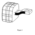
- Figure 1 shows a first embodiment.
- the connector strip cohesively to the connection piece.
- one end of the connector strip is intended to be pressed or cast directly with the connection piece during warm-pressing or metal-casting of the connection piece.
- the total resistance electrical and thermal
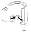
- Figure 2 shows a second embodiment, in which, in addition to the simple embodiment with a single connector strip, a multiple embodiment is also proposed, in which a plurality of connector strips are cohesively connected to an approximately hollow-cylindrical connection piece.
- the connector strips care should be taken to ensure that the electrical resistances of the various electrical paths are virtually equal, so that the current is split uniformly. This can take place by the cross sections of the flexible conductors or of subregions of the connection piece being adjusted.
- Figure 3 shows the side view of the installed state of the embodiment with respect to figure 2 .
- the pressed or fused-in connector strips are standard connector strips which are used in this form in the prior art.
- the connection to the vacuum interrupter chamber then takes place via the existing drilled-through holes in the end faces of the connector strips by means of a pushed-through connection.
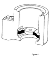
- Figure 4 shows a further design embodiment, namely using a special connector strip, in which two or more flexible conductors are connected in the center to form a common plate.
- the connection can in this case take place by means of various, known methods, such as welding, diffusion welding or soldering.
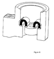
- Figure 6 shows a development of this concept in which, in one step, individual connector strips are cohesively connected to the outer and one inner connection piece.
- the position and the number of the flexible connections used can be selected very differently; a few embodiments are already illustrated in figures 5 and 7 .
- Figure 8 shows a further embodiment of the basic concept in which the use of a sheet membrane or corrugated washer, which is, with a round embodiment, attached to the entire inner circumference of the connection piece or is connected thereto in an interlocking manner, is also proposed.
Landscapes
- Physics & Mathematics (AREA)
- Electromagnetism (AREA)
- Thermally Actuated Switches (AREA)
- Gas-Insulated Switchgears (AREA)
- Braking Arrangements (AREA)
- Current-Collector Devices For Electrically Propelled Vehicles (AREA)
- Connections Effected By Soldering, Adhesion, Or Permanent Deformation (AREA)
- Connector Housings Or Holding Contact Members (AREA)
Abstract
Description
- The invention relates to a low-voltage, medium-voltage or high-voltage switchgear assembly with at least one moveable contact piece, in which the moveable contact is connected to a stationary connection piece electrically with a flexible connecting means, in accordance with the preamble of patent claim 1.
- The technical field relates to switching devices, in particular for the medium-voltage range. These switching devices are equipped with so-called pole parts, in which vacuum interrupter chambers are installed or cast in as actual switching elements.
- The pole parts have two stationary connection pieces, to which the switching device in the switchgear assembly is connected to further components. The stationary connection pieces are connected to the feed lines of the vacuum interrupter chamber within the pole part. This connection can be designed to be rigid on one side, the fixed contact side. On the other side, the switching contact side, the stationary connection piece of the pole part needs to be connected to the moveable feed line of the vacuum interrupter chamber in such a way that a relative movement of the moveable feed line is made possible. This technical object is generally achieved by a rolling contact, a multicontact system or a connector strip.
- Connector strips are usually in the form of separate component parts, which also need to be fitted separately.
-
DE 9017054 U1 has disclosed a switch pole arrangement with a moveable connector strip. This document describes an arrangement of an open pole part, in which a vacuum interrupter chamber is installed in the tubular pole part via corresponding mounts. The moveable feed line is connected to the connection piece of the pole part, in this case in the form of a busbar, by means of a connector strip. The fixing of the connector strip in this case takes place by means of screws. - Ring-type connector strips are also known.
- These have the following disadvantages, however.
The sum of all the electrical resistances in the pole part results, during operation with current flow, in heating of the pole part which should not exceed a specific temperature level (predetermined by standards and material properties). For this reason, in principle methods and solutions are sought for reducing the total resistance of the pole part (greater conductor cross sections, material selection, optimization of the transfer resistances). - The solution which has until now mainly been used of connecting the connector strip to the connection piece of the pole part by means of screw connections has the disadvantage that the connecting point has a relatively high electrical transfer resistance. This is brought about by the only partial surface contact of the connector strip and the connection piece in the region of the screw connection. Furthermore, the screwed connecting point also has the disadvantage of a relatively high thermal resistance. Since the thermal energy which arises in the pole part is principally dissipated via the connection pieces and the conductors connected thereto, the screw connection not only results in an increase in the thermal energy produced but also in a reduction in the thermal conduction and therefore overall in greater heating of the pole part.
- The invention is therefore based on the object of producing a connection between the connector strip and the connection piece of the pole part which has an electrical and thermal resistance which is as low as possible whilst maintaining the mechanical properties of a conventional connector strip solution.
- The object set is achieved in the case of a low-voltage, medium-voltage or high-voltage switchgear assembly of the generic type in accordance with the invention by the characterizing features of claim 1.
- Further advantageous configurations are given in the dependent claims.
- The present invention describes the optimization of the so-called connector strip solution. The essence of the invention is in this case the fact that the flexible connecting means is connected to the connection piece directly or with an intermediate piece, which can be connected to the connection piece, cohesively or at least unreleasably. In this case, the arrangement according to the invention is distinguished from known designs from the prior art.
- In the case of known designs, the connector strip, i.e. the connecting means between the contact piece feed line and the connection piece, is a separate component part, which not only needs to be fitted to the contact piece feed line of the contact piece, but also additionally needs to be fitted to the connection piece. Releasable connections produce transfer resistances, however. As a result of the high potential current levels, a notably high power is released via the transfer resistances, and this results in a heat flow from the conductors.
- In this case moreover the term connection piece is intended to mean that connection piece which runs through the pole part wall for an external contact to the outside.
- In order to reduce thermal heating within the pole part, the transfer resistance between the connecting means (connector strip) and connection piece is drastically reduced by the measure in accordance with the invention. In this case, the connecting point may be a cohesive, in a particular case even a materially cohesive, transition between the connection piece and the connector strip.
- A further configuration provides that the connecting means is integrally formed materially cohesively on the connection piece or on the intermediate piece in such a way that it forms, with the connection piece or the intermediate piece, an integral unit. This is the optimum form which provides the least transfer resistance.
- A further advantageous configuration provides that the connecting point between the connection piece and the connecting means, i.e. the connector strip, for example, is a pressed or cast connection.
- A further advantageous configuration provides that the connection piece is a hollow-cylindrical metallic component part, in which the hollow cylinder is parallel to the contact piece actuation axis and at least one connecting means is arranged within the hollow cylinder and is connected to the hollow cylinder section integrally and materially cohesively or in pressed fashion.
- A further configuration consists in the fact that two connector strips are arranged on diametrically opposite sides and can be attached centrally one above the other to the contact piece feed line of the moveable contact piece.
- Further advantageous is the fact that the connector strips are designed to be flexible.
- A further configuration consists in the fact that the connector strips can be fitted in such a way that they are bent forwards in one direction. In this case, even greater flexibility in the mechanical actuation excursion is made possible.
- A special but likewise effective and advantageous configuration consists in the fact that four connector strips, in each case two diametrically positioned connector strips, are each arranged in such a way that they are bent forwards in one direction.
- A specific embodiment is that a type of sheet membrane is provided as the connecting means, which sheet membrane is connected centrally with screw means on the moveable contact pin and at the edge to the hollow-cylindrical section of the connection piece.
- As a result of the configuration in which the sheet membrane is a concentrically corrugated membrane, increased flexibility when implementing the membrane is achieved.
- The invention is illustrated in the drawing and described in more detail below.
-
- figure 1:
- shows a first embodiment with an integrally formed connector strip,
- figure 2:
- shows a second embodiment with a cylindrical connection piece,
- figure 3:
- shows a side view of the installed state with respect to
figure 2 , - figure 4:
- shows an embodiment as in
figures 2 /3 only with the central connection piece with drilled hole, - figure 5:
- shows an embodiment as above with connector strips bent forward,
- figure 6:
- shows an embodiment as above with connector strips bent forward in the form of a U,
- figure 7:
- shows an embodiment with four bent connector strips, and
- figure 8:
- shows an embodiment with a membrane as the electrical connecting element.
-
Figure 1 shows a first embodiment. In this regard it is proposed to connect the connector strip cohesively to the connection piece. For this purpose, one end of the connector strip is intended to be pressed or cast directly with the connection piece during warm-pressing or metal-casting of the connection piece. This results in an integral connection piece, in which the outer connection piece merges cohesively with the flexible electrical transition. As a result of this measure, the total resistance (electrical and thermal) is markedly reduced in comparison with a screw connection. -
Figure 2 shows a second embodiment, in which, in addition to the simple embodiment with a single connector strip, a multiple embodiment is also proposed, in which a plurality of connector strips are cohesively connected to an approximately hollow-cylindrical connection piece. When arranging the connector strips care should be taken to ensure that the electrical resistances of the various electrical paths are virtually equal, so that the current is split uniformly. This can take place by the cross sections of the flexible conductors or of subregions of the connection piece being adjusted. -
Figure 3 shows the side view of the installed state of the embodiment with respect tofigure 2 . - In the previous arrangements it has been assumed that the pressed or fused-in connector strips are standard connector strips which are used in this form in the prior art. The connection to the vacuum interrupter chamber then takes place via the existing drilled-through holes in the end faces of the connector strips by means of a pushed-through connection.
-
Figure 4 shows a further design embodiment, namely using a special connector strip, in which two or more flexible conductors are connected in the center to form a common plate. The connection can in this case take place by means of various, known methods, such as welding, diffusion welding or soldering. -
Figure 6 shows a development of this concept in which, in one step, individual connector strips are cohesively connected to the outer and one inner connection piece. The position and the number of the flexible connections used can be selected very differently; a few embodiments are already illustrated infigures 5 and7 . -
Figure 8 shows a further embodiment of the basic concept in which the use of a sheet membrane or corrugated washer, which is, with a round embodiment, attached to the entire inner circumference of the connection piece or is connected thereto in an interlocking manner, is also proposed. - As in the case of the connector strips, in this case it would probably be necessary to place a large number of corrugated washers one above the other for sufficient current-carrying capacity. In the essentially air-tight embodiment shown, during switching the compression or decompression of the air enclosed between the membrane and the vacuum interrupter chamber would result in damping of the switching process. This leads to an optimized switching response of the circuit breaker as a result of the reduced rebound response or reverse response during opening of the contact pieces. In order to vary the damping, it is possible to provide the corrugated washers with defined openings (for example drilled holes) in order to produce targeted pressure compensation. In addition, the openings can contribute to the cooling of the current transfer as a result of the air exchange produced.
Claims (10)
- A low-voltage, medium-voltage or high-voltage switchgear assembly with at least one moveable contact piece, in which the moveable contact piece is connected to a connection piece electrically with a flexible connecting means,
wherein
the flexible connecting means is connected to the connection piece directly or with an intermediate piece, which can be connected to the connection piece, cohesively or at least unreleasably. - The low-voltage, medium-voltage or high-voltage switchgear assembly as claimed in claim 1,
wherein
the connecting means is integrally formed materially cohesively on the connection piece or on the intermediate piece in such a way that it forms, with the connection piece or the intermediate piece, an integral unit. - The low-voltage, medium-voltage or high-voltage switchgear assembly as claimed in claim 1,
wherein
the connecting point between the connection piece and the connecting means is a pressed or cast connection. - The low-voltage, medium-voltage or high-voltage switchgear assembly as claimed in claim 1,
wherein
the connection piece is a hollow-cylindrical metallic component part, in which the hollow cylinder is parallel to the contact actuation axis, and at least one connecting means is arranged within the hollow cylinder and is connected to the hollow cylinder section integrally and materially cohesively or in pressed fashion. - The low-voltage, medium-voltage or high-voltage switchgear assembly as claimed in claim 4,
wherein
two connector strips are arranged on diametrically opposite sides as connecting means and can be attached centrally one above the other to the contact piece feed line of the moveable contact. - The low-voltage, medium-voltage or high-voltage switchgear assembly as claimed in claim 5,
wherein
the connector strips are designed to be flexible. - The low-voltage, medium-voltage or high-voltage switchgear assembly as claimed in claim 6,
wherein
the connector strips are fitted such that they are bent forward in one direction. - The low-voltage, medium-voltage or high-voltage switchgear assembly as claimed in claim 7,
wherein
4 connector strips, in each case two diametrically positioned connector strips, are each arranged such that they are bent forward in one direction. - The low-voltage, medium-voltage or high-voltage switchgear assembly as claimed in claim 1,
wherein
a type of sheet-metal membrane is provided as the connecting means, which sheet-metal membrane is connected centrally using screw means on the moveable contact piece feed line and at the edge to the hollow-cylindrical section of the connection piece. - The low-voltage, medium-voltage or high-voltage switchgear assembly as claimed in claim 9,
wherein
the sheet-metal membrane is a concentrically corrugated membrane.
Priority Applications (7)
| Application Number | Priority Date | Filing Date | Title |
|---|---|---|---|
| DE602007013785T DE602007013785D1 (en) | 2007-12-07 | 2007-12-07 | Low, medium or high voltage gearbox assembly with at least one movable contact |
| EP07023713A EP2068331B1 (en) | 2007-12-07 | 2007-12-07 | Low-voltage, medium voltage or high voltage switchgear assembly with at least one moveable contact |
| AT07023713T ATE504931T1 (en) | 2007-12-07 | 2007-12-07 | TRANSMISSION ARRANGEMENT WITH LOW, MEDIUM OR HIGH VOLTAGE AND WITH AT LEAST ONE MOVING CONTACT |
| EP08855853A EP2240945A1 (en) | 2007-12-07 | 2008-12-04 | Low-voltage, medium-voltage or high-voltage switchgear assembly with at least one moveable contact |
| CN200880119719XA CN101889322A (en) | 2007-12-07 | 2008-12-04 | Low pressure, medium-pressure or high pressure switch module with at least one moveable contact |
| PCT/EP2008/010260 WO2009071287A1 (en) | 2007-12-07 | 2008-12-04 | Low-voltage, medium-voltage or high-voltage switchgear assembly with at least one moveable contact |
| US12/795,093 US20100300852A1 (en) | 2007-12-07 | 2010-06-07 | Low-voltage, medium-voltage or high-voltage switchgear assembly with at least one moveable contact |
Applications Claiming Priority (1)
| Application Number | Priority Date | Filing Date | Title |
|---|---|---|---|
| EP07023713A EP2068331B1 (en) | 2007-12-07 | 2007-12-07 | Low-voltage, medium voltage or high voltage switchgear assembly with at least one moveable contact |
Publications (2)
| Publication Number | Publication Date |
|---|---|
| EP2068331A1 true EP2068331A1 (en) | 2009-06-10 |
| EP2068331B1 EP2068331B1 (en) | 2011-04-06 |
Family
ID=39363857
Family Applications (2)
| Application Number | Title | Priority Date | Filing Date |
|---|---|---|---|
| EP07023713A Not-in-force EP2068331B1 (en) | 2007-12-07 | 2007-12-07 | Low-voltage, medium voltage or high voltage switchgear assembly with at least one moveable contact |
| EP08855853A Withdrawn EP2240945A1 (en) | 2007-12-07 | 2008-12-04 | Low-voltage, medium-voltage or high-voltage switchgear assembly with at least one moveable contact |
Family Applications After (1)
| Application Number | Title | Priority Date | Filing Date |
|---|---|---|---|
| EP08855853A Withdrawn EP2240945A1 (en) | 2007-12-07 | 2008-12-04 | Low-voltage, medium-voltage or high-voltage switchgear assembly with at least one moveable contact |
Country Status (6)
| Country | Link |
|---|---|
| US (1) | US20100300852A1 (en) |
| EP (2) | EP2068331B1 (en) |
| CN (1) | CN101889322A (en) |
| AT (1) | ATE504931T1 (en) |
| DE (1) | DE602007013785D1 (en) |
| WO (1) | WO2009071287A1 (en) |
Cited By (1)
| Publication number | Priority date | Publication date | Assignee | Title |
|---|---|---|---|---|
| CN105655193A (en) * | 2016-01-28 | 2016-06-08 | 南京开关厂有限公司 | Vacuum circuit breaker |
Citations (3)
| Publication number | Priority date | Publication date | Assignee | Title |
|---|---|---|---|---|
| US3393389A (en) * | 1960-06-06 | 1968-07-16 | Texas Instruments Inc | Adjustable bridging contact member type thermostatic switch |
| US6751849B1 (en) * | 1999-01-20 | 2004-06-22 | Siemens Aktiengesellschaft | Method for connecting a contact body and a flexible conductor, and a compression mold for carrying out said method |
| DE202006007973U1 (en) * | 2006-05-10 | 2006-08-03 | Siemens Ag | Power circuit breaker to act as full-load switch has pole unit with pole head and pole carrier and vacuum switching tube in-between with fixed and moving contacts |
Family Cites Families (4)
| Publication number | Priority date | Publication date | Assignee | Title |
|---|---|---|---|---|
| DE19636237A1 (en) * | 1996-06-21 | 1998-01-02 | Siemens Ag | Low-voltage circuit-breaker switching contact system |
| DE19712182A1 (en) * | 1997-03-22 | 1998-09-24 | Abb Patent Gmbh | Vacuum chamber |
| US6444939B1 (en) * | 2000-05-09 | 2002-09-03 | Eaton Corporation | Vacuum switch operating mechanism including laminated flexible shunt connector |
| US20080189937A1 (en) * | 2007-02-08 | 2008-08-14 | Singatron Enterprise Co., Ltd. | Method of making a connector with an injection-molding technique |
-
2007
- 2007-12-07 AT AT07023713T patent/ATE504931T1/en not_active IP Right Cessation
- 2007-12-07 DE DE602007013785T patent/DE602007013785D1/en active Active
- 2007-12-07 EP EP07023713A patent/EP2068331B1/en not_active Not-in-force
-
2008
- 2008-12-04 CN CN200880119719XA patent/CN101889322A/en active Pending
- 2008-12-04 WO PCT/EP2008/010260 patent/WO2009071287A1/en active Application Filing
- 2008-12-04 EP EP08855853A patent/EP2240945A1/en not_active Withdrawn
-
2010
- 2010-06-07 US US12/795,093 patent/US20100300852A1/en not_active Abandoned
Patent Citations (3)
| Publication number | Priority date | Publication date | Assignee | Title |
|---|---|---|---|---|
| US3393389A (en) * | 1960-06-06 | 1968-07-16 | Texas Instruments Inc | Adjustable bridging contact member type thermostatic switch |
| US6751849B1 (en) * | 1999-01-20 | 2004-06-22 | Siemens Aktiengesellschaft | Method for connecting a contact body and a flexible conductor, and a compression mold for carrying out said method |
| DE202006007973U1 (en) * | 2006-05-10 | 2006-08-03 | Siemens Ag | Power circuit breaker to act as full-load switch has pole unit with pole head and pole carrier and vacuum switching tube in-between with fixed and moving contacts |
Cited By (1)
| Publication number | Priority date | Publication date | Assignee | Title |
|---|---|---|---|---|
| CN105655193A (en) * | 2016-01-28 | 2016-06-08 | 南京开关厂有限公司 | Vacuum circuit breaker |
Also Published As
| Publication number | Publication date |
|---|---|
| EP2068331B1 (en) | 2011-04-06 |
| ATE504931T1 (en) | 2011-04-15 |
| WO2009071287A1 (en) | 2009-06-11 |
| CN101889322A (en) | 2010-11-17 |
| DE602007013785D1 (en) | 2011-05-19 |
| EP2240945A1 (en) | 2010-10-20 |
| US20100300852A1 (en) | 2010-12-02 |
Similar Documents
| Publication | Publication Date | Title |
|---|---|---|
| KR100625225B1 (en) | Circuit breaker | |
| JP4405265B2 (en) | Vacuum valve with contact for opening and closing | |
| KR100996791B1 (en) | Main circuit terminal assembly for vacuum circuit breake | |
| CN102339694A (en) | Small-sized molded case circuit breaker (MCCB) | |
| CN101667506B (en) | Vaccum circuit breaker | |
| WO2019010890A1 (en) | Gis device and three-phase-in-one-box busbar cylinder thereof | |
| CN105529663B (en) | Busbar assembly and the Cubicle Gas-Insulated Switchgear using the busbar assembly | |
| US6444939B1 (en) | Vacuum switch operating mechanism including laminated flexible shunt connector | |
| EP2068331B1 (en) | Low-voltage, medium voltage or high voltage switchgear assembly with at least one moveable contact | |
| CN111952111B (en) | Double-fracture quick vacuum arc extinguish chamber | |
| CN202495394U (en) | Circuit breaker, switch device and power transmission system | |
| CN108511259B (en) | A utmost point post and vacuum circuit breaker that be used for subassembly of being qualified for next round of competitions of utmost point post, be used for vacuum circuit breaker | |
| EP2306482B1 (en) | Main circuit terminal assembly for vacuum circuit breaker | |
| EP2747113B1 (en) | Circuit-breaker pole part with a flexible conductor for connecting a movable electrical contact | |
| CN101409176B (en) | Major loop structure for vacuum circuit-breaker | |
| CN215266071U (en) | Movable end flexible connection structure for vacuum circuit breaker | |
| CN207116240U (en) | One kind is applied to high-tension apparatus high-current switch contact | |
| CN216818194U (en) | Circuit breaker structure | |
| IT1314039B1 (en) | ELECTRIC POLE FOR LOW VOLTAGE POWER SWITCH. | |
| CN111164718B (en) | Module group for constructing power switch | |
| CN216818958U (en) | Integrated contact box for switch equipment | |
| CN203312238U (en) | Novel fuse | |
| CN101438361B (en) | Power switch especially great current switch | |
| WO2023100303A1 (en) | Circuit breaker | |
| CN208174123U (en) | A kind of drawout breaker |
Legal Events
| Date | Code | Title | Description |
|---|---|---|---|
| PUAI | Public reference made under article 153(3) epc to a published international application that has entered the european phase |
Free format text: ORIGINAL CODE: 0009012 |
|
| AK | Designated contracting states |
Kind code of ref document: A1 Designated state(s): AT BE BG CH CY CZ DE DK EE ES FI FR GB GR HU IE IS IT LI LT LU LV MC MT NL PL PT RO SE SI SK TR |
|
| AX | Request for extension of the european patent |
Extension state: AL BA HR MK RS |
|
| 17P | Request for examination filed |
Effective date: 20091210 |
|
| AKX | Designation fees paid |
Designated state(s): AT BE BG CH CY CZ DE DK EE ES FI FR GB GR HU IE IS IT LI LT LU LV MC MT NL PL PT RO SE SI SK TR |
|
| 17Q | First examination report despatched |
Effective date: 20100127 |
|
| GRAP | Despatch of communication of intention to grant a patent |
Free format text: ORIGINAL CODE: EPIDOSNIGR1 |
|
| RIN1 | Information on inventor provided before grant (corrected) |
Inventor name: RUEMENAPP, TILL DR.-ING. Inventor name: HUMPERT, CHRISTOF, DR. -ING. Inventor name: GENTSCH, DIETMAR DR.-ING. |
|
| GRAS | Grant fee paid |
Free format text: ORIGINAL CODE: EPIDOSNIGR3 |
|
| GRAA | (expected) grant |
Free format text: ORIGINAL CODE: 0009210 |
|
| AK | Designated contracting states |
Kind code of ref document: B1 Designated state(s): AT BE BG CH CY CZ DE DK EE ES FI FR GB GR HU IE IS IT LI LT LU LV MC MT NL PL PT RO SE SI SK TR |
|
| REG | Reference to a national code |
Ref country code: GB Ref legal event code: FG4D |
|
| REG | Reference to a national code |
Ref country code: CH Ref legal event code: EP |
|
| REG | Reference to a national code |
Ref country code: IE Ref legal event code: FG4D |
|
| REF | Corresponds to: |
Ref document number: 602007013785 Country of ref document: DE Date of ref document: 20110519 Kind code of ref document: P |
|
| REG | Reference to a national code |
Ref country code: DE Ref legal event code: R096 Ref document number: 602007013785 Country of ref document: DE Effective date: 20110519 |
|
| REG | Reference to a national code |
Ref country code: NL Ref legal event code: T3 |
|
| PG25 | Lapsed in a contracting state [announced via postgrant information from national office to epo] |
Ref country code: SI Free format text: LAPSE BECAUSE OF FAILURE TO SUBMIT A TRANSLATION OF THE DESCRIPTION OR TO PAY THE FEE WITHIN THE PRESCRIBED TIME-LIMIT Effective date: 20110406 |
|
| LTIE | Lt: invalidation of european patent or patent extension |
Effective date: 20110406 |
|
| PG25 | Lapsed in a contracting state [announced via postgrant information from national office to epo] |
Ref country code: LT Free format text: LAPSE BECAUSE OF FAILURE TO SUBMIT A TRANSLATION OF THE DESCRIPTION OR TO PAY THE FEE WITHIN THE PRESCRIBED TIME-LIMIT Effective date: 20110406 Ref country code: PT Free format text: LAPSE BECAUSE OF FAILURE TO SUBMIT A TRANSLATION OF THE DESCRIPTION OR TO PAY THE FEE WITHIN THE PRESCRIBED TIME-LIMIT Effective date: 20110808 Ref country code: SE Free format text: LAPSE BECAUSE OF FAILURE TO SUBMIT A TRANSLATION OF THE DESCRIPTION OR TO PAY THE FEE WITHIN THE PRESCRIBED TIME-LIMIT Effective date: 20110406 |
|
| PG25 | Lapsed in a contracting state [announced via postgrant information from national office to epo] |
Ref country code: CY Free format text: LAPSE BECAUSE OF FAILURE TO SUBMIT A TRANSLATION OF THE DESCRIPTION OR TO PAY THE FEE WITHIN THE PRESCRIBED TIME-LIMIT Effective date: 20110406 Ref country code: IS Free format text: LAPSE BECAUSE OF FAILURE TO SUBMIT A TRANSLATION OF THE DESCRIPTION OR TO PAY THE FEE WITHIN THE PRESCRIBED TIME-LIMIT Effective date: 20110806 Ref country code: ES Free format text: LAPSE BECAUSE OF FAILURE TO SUBMIT A TRANSLATION OF THE DESCRIPTION OR TO PAY THE FEE WITHIN THE PRESCRIBED TIME-LIMIT Effective date: 20110717 Ref country code: BE Free format text: LAPSE BECAUSE OF FAILURE TO SUBMIT A TRANSLATION OF THE DESCRIPTION OR TO PAY THE FEE WITHIN THE PRESCRIBED TIME-LIMIT Effective date: 20110406 Ref country code: LV Free format text: LAPSE BECAUSE OF FAILURE TO SUBMIT A TRANSLATION OF THE DESCRIPTION OR TO PAY THE FEE WITHIN THE PRESCRIBED TIME-LIMIT Effective date: 20110406 Ref country code: GR Free format text: LAPSE BECAUSE OF FAILURE TO SUBMIT A TRANSLATION OF THE DESCRIPTION OR TO PAY THE FEE WITHIN THE PRESCRIBED TIME-LIMIT Effective date: 20110707 Ref country code: AT Free format text: LAPSE BECAUSE OF FAILURE TO SUBMIT A TRANSLATION OF THE DESCRIPTION OR TO PAY THE FEE WITHIN THE PRESCRIBED TIME-LIMIT Effective date: 20110406 Ref country code: FI Free format text: LAPSE BECAUSE OF FAILURE TO SUBMIT A TRANSLATION OF THE DESCRIPTION OR TO PAY THE FEE WITHIN THE PRESCRIBED TIME-LIMIT Effective date: 20110406 |
|
| PG25 | Lapsed in a contracting state [announced via postgrant information from national office to epo] |
Ref country code: EE Free format text: LAPSE BECAUSE OF FAILURE TO SUBMIT A TRANSLATION OF THE DESCRIPTION OR TO PAY THE FEE WITHIN THE PRESCRIBED TIME-LIMIT Effective date: 20110406 |
|
| PGFP | Annual fee paid to national office [announced via postgrant information from national office to epo] |
Ref country code: FR Payment date: 20120105 Year of fee payment: 5 Ref country code: NL Payment date: 20111228 Year of fee payment: 5 |
|
| PLBE | No opposition filed within time limit |
Free format text: ORIGINAL CODE: 0009261 |
|
| STAA | Information on the status of an ep patent application or granted ep patent |
Free format text: STATUS: NO OPPOSITION FILED WITHIN TIME LIMIT |
|
| PG25 | Lapsed in a contracting state [announced via postgrant information from national office to epo] |
Ref country code: DK Free format text: LAPSE BECAUSE OF FAILURE TO SUBMIT A TRANSLATION OF THE DESCRIPTION OR TO PAY THE FEE WITHIN THE PRESCRIBED TIME-LIMIT Effective date: 20110406 Ref country code: SK Free format text: LAPSE BECAUSE OF FAILURE TO SUBMIT A TRANSLATION OF THE DESCRIPTION OR TO PAY THE FEE WITHIN THE PRESCRIBED TIME-LIMIT Effective date: 20110406 Ref country code: RO Free format text: LAPSE BECAUSE OF FAILURE TO SUBMIT A TRANSLATION OF THE DESCRIPTION OR TO PAY THE FEE WITHIN THE PRESCRIBED TIME-LIMIT Effective date: 20110406 Ref country code: PL Free format text: LAPSE BECAUSE OF FAILURE TO SUBMIT A TRANSLATION OF THE DESCRIPTION OR TO PAY THE FEE WITHIN THE PRESCRIBED TIME-LIMIT Effective date: 20110406 |
|
| 26N | No opposition filed |
Effective date: 20120110 |
|
| REG | Reference to a national code |
Ref country code: DE Ref legal event code: R097 Ref document number: 602007013785 Country of ref document: DE Effective date: 20120110 |
|
| PGFP | Annual fee paid to national office [announced via postgrant information from national office to epo] |
Ref country code: DE Payment date: 20111222 Year of fee payment: 5 |
|
| PGFP | Annual fee paid to national office [announced via postgrant information from national office to epo] |
Ref country code: IT Payment date: 20111222 Year of fee payment: 5 |
|
| PG25 | Lapsed in a contracting state [announced via postgrant information from national office to epo] |
Ref country code: MC Free format text: LAPSE BECAUSE OF NON-PAYMENT OF DUE FEES Effective date: 20111231 |
|
| REG | Reference to a national code |
Ref country code: CH Ref legal event code: PL |
|
| GBPC | Gb: european patent ceased through non-payment of renewal fee |
Effective date: 20111207 |
|
| REG | Reference to a national code |
Ref country code: IE Ref legal event code: MM4A |
|
| PG25 | Lapsed in a contracting state [announced via postgrant information from national office to epo] |
Ref country code: GB Free format text: LAPSE BECAUSE OF NON-PAYMENT OF DUE FEES Effective date: 20111207 Ref country code: LI Free format text: LAPSE BECAUSE OF NON-PAYMENT OF DUE FEES Effective date: 20111231 Ref country code: CH Free format text: LAPSE BECAUSE OF NON-PAYMENT OF DUE FEES Effective date: 20111231 Ref country code: IE Free format text: LAPSE BECAUSE OF NON-PAYMENT OF DUE FEES Effective date: 20111207 |
|
| PGFP | Annual fee paid to national office [announced via postgrant information from national office to epo] |
Ref country code: CZ Payment date: 20121130 Year of fee payment: 6 |
|
| PG25 | Lapsed in a contracting state [announced via postgrant information from national office to epo] |
Ref country code: MT Free format text: LAPSE BECAUSE OF FAILURE TO SUBMIT A TRANSLATION OF THE DESCRIPTION OR TO PAY THE FEE WITHIN THE PRESCRIBED TIME-LIMIT Effective date: 20110406 |
|
| PG25 | Lapsed in a contracting state [announced via postgrant information from national office to epo] |
Ref country code: LU Free format text: LAPSE BECAUSE OF NON-PAYMENT OF DUE FEES Effective date: 20111207 |
|
| PG25 | Lapsed in a contracting state [announced via postgrant information from national office to epo] |
Ref country code: BG Free format text: LAPSE BECAUSE OF FAILURE TO SUBMIT A TRANSLATION OF THE DESCRIPTION OR TO PAY THE FEE WITHIN THE PRESCRIBED TIME-LIMIT Effective date: 20110706 |
|
| REG | Reference to a national code |
Ref country code: NL Ref legal event code: V1 Effective date: 20130701 |
|
| REG | Reference to a national code |
Ref country code: FR Ref legal event code: ST Effective date: 20130830 |
|
| PG25 | Lapsed in a contracting state [announced via postgrant information from national office to epo] |
Ref country code: TR Free format text: LAPSE BECAUSE OF FAILURE TO SUBMIT A TRANSLATION OF THE DESCRIPTION OR TO PAY THE FEE WITHIN THE PRESCRIBED TIME-LIMIT Effective date: 20110406 |
|
| REG | Reference to a national code |
Ref country code: DE Ref legal event code: R119 Ref document number: 602007013785 Country of ref document: DE Effective date: 20130702 |
|
| PG25 | Lapsed in a contracting state [announced via postgrant information from national office to epo] |
Ref country code: DE Free format text: LAPSE BECAUSE OF NON-PAYMENT OF DUE FEES Effective date: 20130702 Ref country code: NL Free format text: LAPSE BECAUSE OF NON-PAYMENT OF DUE FEES Effective date: 20130701 Ref country code: HU Free format text: LAPSE BECAUSE OF FAILURE TO SUBMIT A TRANSLATION OF THE DESCRIPTION OR TO PAY THE FEE WITHIN THE PRESCRIBED TIME-LIMIT Effective date: 20110406 |
|
| PG25 | Lapsed in a contracting state [announced via postgrant information from national office to epo] |
Ref country code: FR Free format text: LAPSE BECAUSE OF NON-PAYMENT OF DUE FEES Effective date: 20130102 |
|
| PG25 | Lapsed in a contracting state [announced via postgrant information from national office to epo] |
Ref country code: IT Free format text: LAPSE BECAUSE OF NON-PAYMENT OF DUE FEES Effective date: 20121207 |
|
| PG25 | Lapsed in a contracting state [announced via postgrant information from national office to epo] |
Ref country code: CZ Free format text: LAPSE BECAUSE OF NON-PAYMENT OF DUE FEES Effective date: 20131207 |