EP2068295B1 - Laparoscopic training apparatus - Google Patents
Laparoscopic training apparatus Download PDFInfo
- Publication number
- EP2068295B1 EP2068295B1 EP08020955.4A EP08020955A EP2068295B1 EP 2068295 B1 EP2068295 B1 EP 2068295B1 EP 08020955 A EP08020955 A EP 08020955A EP 2068295 B1 EP2068295 B1 EP 2068295B1
- Authority
- EP
- European Patent Office
- Prior art keywords
- laparoscopic
- section
- socket
- sections
- joint
- Prior art date
- Legal status (The legal status is an assumption and is not a legal conclusion. Google has not performed a legal analysis and makes no representation as to the accuracy of the status listed.)
- Not-in-force
Links
Images


Classifications
-
- G—PHYSICS
- G09—EDUCATION; CRYPTOGRAPHY; DISPLAY; ADVERTISING; SEALS
- G09B—EDUCATIONAL OR DEMONSTRATION APPLIANCES; APPLIANCES FOR TEACHING, OR COMMUNICATING WITH, THE BLIND, DEAF OR MUTE; MODELS; PLANETARIA; GLOBES; MAPS; DIAGRAMS
- G09B23/00—Models for scientific, medical, or mathematical purposes, e.g. full-sized devices for demonstration purposes
- G09B23/28—Models for scientific, medical, or mathematical purposes, e.g. full-sized devices for demonstration purposes for medicine
- G09B23/285—Models for scientific, medical, or mathematical purposes, e.g. full-sized devices for demonstration purposes for medicine for injections, endoscopy, bronchoscopy, sigmoidscopy, insertion of contraceptive devices or enemas
-
- A—HUMAN NECESSITIES
- A61—MEDICAL OR VETERINARY SCIENCE; HYGIENE
- A61B—DIAGNOSIS; SURGERY; IDENTIFICATION
- A61B34/00—Computer-aided surgery; Manipulators or robots specially adapted for use in surgery
- A61B34/70—Manipulators specially adapted for use in surgery
- A61B34/76—Manipulators having means for providing feel, e.g. force or tactile feedback
-
- A—HUMAN NECESSITIES
- A61—MEDICAL OR VETERINARY SCIENCE; HYGIENE
- A61B—DIAGNOSIS; SURGERY; IDENTIFICATION
- A61B17/00—Surgical instruments, devices or methods, e.g. tourniquets
- A61B2017/00681—Aspects not otherwise provided for
- A61B2017/00707—Dummies, phantoms; Devices simulating patient or parts of patient
- A61B2017/00716—Dummies, phantoms; Devices simulating patient or parts of patient simulating physical properties
Definitions
- the present invention relates to a laparoscopic apparatus.
- the invention finds utility as a training apparatus for laparoscopic surgery techniques.
- Laparoscopic surgery is a modem surgical technique performed through small incisions, which involves the visualisation of body cavities using telescopes with attached camera systems. Trocars or cannulae are inserted through the incisions to facilitate the smooth passage of telescopes and slender long instruments into these cavities.
- a fundamental feature of laparoscopic surgery is the use of a laparoscope: a telescopic rod lens system that is usually connected to a visual acquisition device, such as a camera. Most typically, a fibre optic cable system connected to a 'cold' light source such as halogen or xenon is used to illuminate the operative field.
- the internal appearances of the body cavities are visualised on visual display monitors. The monitor image is 2-dimensional, and the movement of the instruments is seen in parallax.
- a simulator replicating the laparoscopic environment as experienced in an operating theatre is superior to other inanimate simulators. Any learned procedure is a combination of several different skills, in other words all procedures can be broken down into individual component skills. These skills include the ability to correctly orientate a camera, manipulate objects in 3 dimensions, cut tissue, and suture (stitch). The simulator facilitates the trainee in attaining proficiency at these tasks prior to actually entering the operating room environment.
- a simulator can also help simulate an entire procedure, where the skills are combined on a suitable model, again without endangering a patient.
- a laparoscopic cholecystectomy removal of a gall bladder
- the most common laparoscopic procedure performed is a combination of grasping, dissection, clipping and cutting. All these skills can be simulated and indeed the procedure itself can then be performed on a simple model.
- a laparoscopic apparatus according to the preamble of claim 1 is disclosed in US 2004/024418 A1 .
- the present invention will provide a realistic surgical experience by mimicking the sensation of carrying out surgical techniques on a patient.
- a laparoscopic apparatus comprising a housing; a joint in operative association with the housing and adapted to substantially accommodate a laparoscopic tool, in use, through the joint, the joint permitting movement of the laparoscopic tool, in use; and resistance means in operative association with the joint, adapted to provide resistance to movement of the laparoscopic tool, in use.
- the housing comprises a base and a lid.
- the lid is generally curved in form, to substantially mimic the form of a human torso.
- the laparoscopic tool is a visual acquisition device.
- the joint further comprises a substantially hollow generally cylindrical tube, which is open at both ends.
- the joint permits concurrent movement of the laparoscopic tool (for example, the visual acquisition device) in all three axes.
- the joint is a rotatable joint.
- the joint is adapted to simulate the resistive forces experienced during laparoscopic surgical techniques.
- the joint comprises a ball-and-socket joint.
- the joint comprises a ball rotatably enagagable within a socket
- the joint comprises a ball, and a socket within which the ball is at least partially housed; the ball being rotatably engagable within the socket, and the socket being adapted to provide resistance to movement of the ball.
- the socket is generally annular in form, and shaped and dimensioned to accommodate the ball therein.
- the ball is generally conoid.
- the ball can be any form that permits triaxial rotation within the socket.
- the socket comprises a first section and a second section, spaced apart, shaped and dimensioned to house the ball therebetween.
- the socket comprises a first section, and a second section spaced apart by a distance from the first section; the socket being shaped and dimensioned to house the ball therebetween.
- the first section can be removably mounted to the housing of the laparoscopic apparatus.
- the first section is mounted by a plurality of clips.
- the first and second sections are biased towards one another by the resistance means.
- the first and second sections are biased away from one another by the resistance means.
- the resistance means may comprise at least one resiliently deformable resilient member.
- the at least one resilient member extends between the first and second sections of the socket.
- the resilient member is in operable association with one or both of the first and second sections of the socket.
- at least one of a respective terminal end of the resilient member is attached to one or both of the first and second sections.
- the resilient member is elastic.
- the resilient member comprises a spring.
- the spring may be, for example, a torsion spring, such as a coil spring or helical spring; or a flat spring, such as a leaf spring.
- the spring may be a compression spring or a tension spring.
- the coil or helical spring may be a compression coil or a tension coil.
- the distance between the first and second sections of the socket is defined by the spring in operable association with one or both of the first and second sections.
- the spring extends between the first and second sections.
- the resistance is adjustable by altering the pressure applied to the ball by the socket.
- the resistance is adjustable, by altering the distance between the first and second sections of the socket.
- the resistance means further comprises means to adjust the distance between the first and second sections of the socket.
- the adjusting means can be in operable association with one or both of the first and second sections.
- the adjusting means further comprises at least one actuator, which facilitates the adjustment of the relative distance between the first and second sections.
- the at least one actuator is a screw fixing.
- the spring is loaded by a screw fixing.
- a buffer is provided between the first and second sections of the socket. Further optionally, a buffer is provided between the ball and at least one of the first and second sections. Preferably, the buffer is formed from a deformable material, such as rubber.
- the housing of the laparoscopic apparatus further comprises one or more apertures through each of which a laparoscopic tool can pass, in use; the aperture being overlaid by a membrane to at least partially resist the laparoscopic tool, when the laparoscopic tool is applied thereto. It will be appreciated that when there are several apertures, the respective laparoscopic tools can be the same or different.
- the membrane comprises a synthetic skin. Further preferably, the membrane comprises a pad.
- the pad is adapted to simulate the resistive forces experienced during laparoscopic surgical techniques.
- the pad comprises an outer membrane, and a core.
- the outer membrane at least partially surrounds the surface of the core.
- the outer membrane is formed from at least one synthetic material selected from the group including, but not limited to: synthetic latex, natural latex, a silicone elastomer, and a hydrocarbon solvent.
- the synthetic material is inert.
- the hydrocarbon solvent is a medium evaporating hydrocarbon solvent.
- the core comprises at least one silicone elastomer.
- the silicone elastomer is a pourable room temperature vulcanising silicone rubber. Further preferably, it holds a Shore A Hardness of about 14.
- the core further comprises a liquid silicone elastomer.
- the pad is flexible.
- it is extensible.
- the housing defines an internal chamber having a platform.
- the position of the platform relative to the opening is adjustable.
- the laparoscopic apparatus further comprises a moveable platform.
- the movable platform is located within the base of the laparoscopic apparatus.
- the platform comprises a first side and second side, the position of at least one of the first side and the second being adjustable relative to the opening.
- each side of the platform can be altered independently of any other side.
- a drawer is provided in the laparoscopic apparatus to accommodate instruments or any similar implements.
- laparoscopic tool is any instrument that may be used during the course of a laparoscopic operation, and is intended to include, but is not limited to cannulae, telescopes, and trocars.
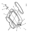
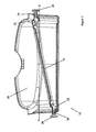
- the laparoscopic apparatus 10 comprises a base section 12, and a lid section 14.
- FIG. 2 is an exploded perspective view of the base section 12 of the laparoscopic apparatus 10.
- the base section 12 comprises a hollow substantially parallelepiped-shaped body 16, with an open, in use, uppermost face.
- a generally planar platform 18 is located within the body 16, and is of similar size to a, in use, bottom face of the body 16.
- a generally obround-shaped elongate aperture 20 is provided on at least one face of the body. Each elongate aperture 20 is substantially perpendicular to the longitudinal axis of the body 16.
- a hinge projection 22 is provided, which is cooperably attached to at least one side of the platform 18. The hinge projection 22 facilitates relative rotational motion between the platform 18 and the hinge projection 22.
- a screw threaded fixing bolt 26 is provided, which locates through the elongate aperture 20, and engages with the hinge projection 22 (See Figure 3 ).
- An annular washer 24 is provided, which locates between the face of the body 16 and the fixing bolt 26, and engages with a numerical scale rule 25 to facilitate accurate quantitative placement of the hinge projection 22 relative to the elongate aperture 20. Adjusting the position of the fixing bolt 26 relative to the elongate aperture 20 can thereby temporarily alter the relative height of the side of the platform 18.
- a generally planar elliptical-shaped mount 28 is provided on each of two respective opposing sides of the body 16, and each is substantially parallel to and continuous with the respective sides of the body 16.
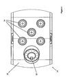
- FIG 4 is a plan view of the lid section 14 of the laparoscopic apparatus 10.
- the lid section 14 is generally rectangular in shape, and curved in form, Figure 1 .
- a number of apertures 34 are provided through the lid section 14.
- a joint 32 is provided through which, a laparoscopic tool 42, Figure 6 , can be mounted.
- FIG 5 is an exploded perspective view of the joint 32, which comprises a socket 35 and a ball 39.
- the socket 35 comprises an annular second section 36, which is inter-engaging with an annular first section 36'.
- the ball 39 comprises a generally hemi-spherical outer member 40' and a generally hemi-spherical inner member 40.
- a generally hollow cylindrical tube 41 is provided through each of the hemi-spherical members 40,40', and, in use, is substantially coaxial with the socket 35.
- the socket 35 interengages with the ball 39, facilitating rotation of the ball 39 through multiple planes relative to the socket 35.
- the first annular section 36' is spaced a distance apart from the second annular section 36, and the ball 39 is housed therebetween.
- the distance between the first annular section 36' and the second annular section 36 is defined by resistance means in the form of four springs 38.
- the springs 38 extend between each of the first annular section 36' and the second annular section 36.
- the spring 38 is a compression spring, whereby the first annular section 36' and the second annular section 36 are biased away from each other.
- the spring 38 is a tension spring, whereby the first annular section 36' and the second annular section 36 are biased toward each other. In either case, the respective terminal ends of the spring 38 can be attached to one or both of the first annular section 36' and the second annular section 36.
- the socket 35 may be formed from a resilient material, which can be adapted to apply varying pressure to the ball 39.
- the socket 35 is the resistance means.
- Each screw 38' extends between the first annular section 36' and the second annular section 36, and is in operable association with either of the sections 36, 36'.
- the first annular section 36' is provided with a complementary screw thread (not shown), with which each of the screws 38' can reversible engage, in use. Rotation of the screw 38' in a first direction will advance the screw 38' toward the first annular section 36', thereby decreasing the distance between the first annular section 36' and the second annular section 36. Rotation of the screw 38' in a second, opposing direction will retract the screw 38' toward the first annular section 36', thereby increasing the distance between the first annular section 36' and the second annular section 36.
- Figure 6 is a cross-sectional side view of the joint 32, in use, with a laparoscopic tool 42 mounted thereto.
- the first section 36' of the socket 35 is attached to the lid section 14, Figure 4 , by a set of clips 37.
- the second section 36 of the socket 35 is attached to the first section 36' by four spring biased screws 38, 38', surrounding the hemi-spherical members 40,40' of the ball 39.
- the ball 39 is positioned between the first section 36' and the second section 36 of the socket 35.
- the spring biased screws 38, 38' allow the level of friction to be adjusted between the first section 36' and the second section 36 of the socket 35, resultantly adjusting the friction between the socket 35 and the ball 39.
- the laparoscopic tool 42 is a telescope comprising a camera 44, which is mounted within the telescope body.
- An optical connection 46 transmits visual graphics from the camera 44 to a visual display unit (not shown).
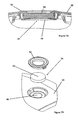
- Figure 7A is a cross-sectional view of an aperture 34 of the lid section 14 of the laparoscopic apparatus 10.
- the aperture 34 comprises an annular housing 52 and a pad 50.
- the pad 50 is generally cylindrical in shape.
- the annular housing 52 is generally annular in form and is shaped and dimensioned to accommodate the pad 50, within the inner edge of the annular housing 52.
- the annular housing 52 locates in a recessed opening 48 in the housing 30 of the lid section 14 of the laparoscopic apparatus 10.
- the pad 50 is formed from a material that is deformable under a first given pressure, but is severable under a second higher given pressure, so as to provide a realistic response representative of skin, when an instrument is applied with force against the pad 50.
- the present invention finds utility in the training of medical professionals, such as trainee surgeons.
- the present invention finds utility as an affordable and portable platform that effectively demonstrates or trains laparoscopic skills and techniques by providing a realistic physical experience with real-time interaction outside of the operating room.
- the present invention allows a trainee surgeon to master the skills required to compensate for the narrow field of view, limitation of work space, and the lack of depth sensation associated with this field of surgery.
- the shape and dimension of the apparatus offers a realistic semblance to the human torso; and the integrated adaptable joint allows for a variety of laparoscopic instruments, including canullae, trocars and telescopes, to be used in a realistic fashion to augment both basic and advanced laparoscopic experiences, and ultimately to develop the coordination, technique, and precision of the trainee surgeon.
- the incision pads also lend to the realistic experience by mimicking the response of human skin to the application of a surgical instrument.
- Use of the invention in cooperative association with a visual display system also affords the user the opportunity to become acquainted with visualising a 3-dimensional operative field as a 2-dimensional output, and the imposition associated therewith.
- the simple and lightweight design makes the apparatus easy to assemble and transport.
- the present invention provides a realistic surgical experience, by simulating the response of an actual human torso, without endangering patients or animal models.
Landscapes
- Engineering & Computer Science (AREA)
- Health & Medical Sciences (AREA)
- Medical Informatics (AREA)
- General Physics & Mathematics (AREA)
- Physics & Mathematics (AREA)
- Surgery (AREA)
- Life Sciences & Earth Sciences (AREA)
- General Health & Medical Sciences (AREA)
- Chemical & Material Sciences (AREA)
- Algebra (AREA)
- Animal Behavior & Ethology (AREA)
- Heart & Thoracic Surgery (AREA)
- Public Health (AREA)
- Veterinary Medicine (AREA)
- Pulmonology (AREA)
- Radiology & Medical Imaging (AREA)
- Biomedical Technology (AREA)
- Medicinal Chemistry (AREA)
- Robotics (AREA)
- Molecular Biology (AREA)
- Computational Mathematics (AREA)
- Nuclear Medicine, Radiotherapy & Molecular Imaging (AREA)
- Mathematical Analysis (AREA)
- Mathematical Optimization (AREA)
- Mathematical Physics (AREA)
- Pure & Applied Mathematics (AREA)
- Business, Economics & Management (AREA)
- Educational Administration (AREA)
- Educational Technology (AREA)
- Theoretical Computer Science (AREA)
- Surgical Instruments (AREA)
- Instructional Devices (AREA)
Description
- The present invention relates to a laparoscopic apparatus. In particular, the invention finds utility as a training apparatus for laparoscopic surgery techniques.
- Laparoscopic surgery is a modem surgical technique performed through small incisions, which involves the visualisation of body cavities using telescopes with attached camera systems. Trocars or cannulae are inserted through the incisions to facilitate the smooth passage of telescopes and slender long instruments into these cavities. A fundamental feature of laparoscopic surgery is the use of a laparoscope: a telescopic rod lens system that is usually connected to a visual acquisition device, such as a camera. Most typically, a fibre optic cable system connected to a 'cold' light source such as halogen or xenon is used to illuminate the operative field. The internal appearances of the body cavities are visualised on visual display monitors. The monitor image is 2-dimensional, and the movement of the instruments is seen in parallax. These combined features mean that surgeons training in this field of surgery not only have to learn individual surgical procedures, they must also become comfortable working in a 3-dimensional environment which has been translated to a 2-dimensional output.
- The restricted vision, the difficulty in handling of the instruments, the acquisition of new hand-eye coordination skills, the lack of tactile perception and the limited working area are factors which add to the technical complexity of this surgical approach. For these reasons, minimally invasive surgery has emerged as a highly competitive new sub-specialty within various fields of surgery. Surgical residents, who wish to focus on this area of surgery, gain additional training during one or two years of fellowship after completing their basic surgical residency. Accordingly, the use of a simulator allows the trainee surgeon not only to learn the skills that when eventually combined, become a procedure, but they can also experience the unique appreciation of 2-dimensional visualisation of the 3-dimensional surgical field.
- A simulator replicating the laparoscopic environment as experienced in an operating theatre, is superior to other inanimate simulators. Any learned procedure is a combination of several different skills, in other words all procedures can be broken down into individual component skills. These skills include the ability to correctly orientate a camera, manipulate objects in 3 dimensions, cut tissue, and suture (stitch). The simulator facilitates the trainee in attaining proficiency at these tasks prior to actually entering the operating room environment.
- Once a surgical trainee or surgeon acquires a skills set, they can then move on to performing a variety of surgical procedures. It is estimated that individual skills have to be repeated up to 30 times before a surgeon is considered proficient. This also applies to entire procedures. A simulator can also help simulate an entire procedure, where the skills are combined on a suitable model, again without endangering a patient. For example a laparoscopic cholecystectomy (removal of a gall bladder), the most common laparoscopic procedure performed, is a combination of grasping, dissection, clipping and cutting. All these skills can be simulated and indeed the procedure itself can then be performed on a simple model.
- A laparoscopic apparatus according to the preamble of claim 1 is disclosed in
US 2004/024418 A1 . - It is an object of the present invention to provide a laparoscopic apparatus for the training of medical professionals, particularly those engaged in the field of laparoscopic surgery. In particular, it is envisaged that the present invention will provide a realistic surgical experience by mimicking the sensation of carrying out surgical techniques on a patient.
- According to the present invention as defined in claim 1, there is provided a laparoscopic apparatus comprising a housing; a joint in operative association with the housing and adapted to substantially accommodate a laparoscopic tool, in use, through the joint, the joint permitting movement of the laparoscopic tool, in use; and resistance means in operative association with the joint, adapted to provide resistance to movement of the laparoscopic tool, in use.
- Preferably, the housing comprises a base and a lid.
- Preferably, the lid is generally curved in form, to substantially mimic the form of a human torso.
- Preferably, the laparoscopic tool is a visual acquisition device.
- Preferably, the joint further comprises a substantially hollow generally cylindrical tube, which is open at both ends.
- Preferably, the joint permits concurrent movement of the laparoscopic tool (for example, the visual acquisition device) in all three axes. Further preferably, the joint is a rotatable joint.
- Preferably, the joint is adapted to simulate the resistive forces experienced during laparoscopic surgical techniques.
- The joint comprises a ball-and-socket joint. The joint comprises a ball rotatably enagagable within a socket
- The joint comprises a ball, and a socket within which the ball is at least partially housed; the ball being rotatably engagable within the socket, and the socket being adapted to provide resistance to movement of the ball.
- Preferably, the socket is generally annular in form, and shaped and dimensioned to accommodate the ball therein.
- Preferably, the ball is generally conoid. Although, it will be seen that the ball can be any form that permits triaxial rotation within the socket.
- The socket comprises a first section and a second section, spaced apart, shaped and dimensioned to house the ball therebetween. The socket comprises a first section, and a second section spaced apart by a distance from the first section; the socket being shaped and dimensioned to house the ball therebetween.
- Preferably, the first section can be removably mounted to the housing of the laparoscopic apparatus. Preferably, the first section is mounted by a plurality of clips.
- Preferably, the first and second sections are biased towards one another by the resistance means. Alternatively, the first and second sections are biased away from one another by the resistance means. The resistance means may comprise at least one resiliently deformable resilient member. Preferably, the at least one resilient member extends between the first and second sections of the socket. Optionally, the resilient member is in operable association with one or both of the first and second sections of the socket. Further optionally, at least one of a respective terminal end of the resilient member is attached to one or both of the first and second sections.
- Preferably, the resilient member is elastic.
- Optionally, the resilient member comprises a spring. The spring may be, for example, a torsion spring, such as a coil spring or helical spring; or a flat spring, such as a leaf spring. The spring may be a compression spring or a tension spring. The coil or helical spring may be a compression coil or a tension coil.
- Preferably, the distance between the first and second sections of the socket is defined by the spring in operable association with one or both of the first and second sections.
- Preferably, the spring extends between the first and second sections.
- Preferably, the resistance is adjustable by altering the pressure applied to the ball by the socket.
- The resistance is adjustable, by altering the distance between the first and second sections of the socket.
- Optionally, the resistance means further comprises means to adjust the distance between the first and second sections of the socket. The adjusting means can be in operable association with one or both of the first and second sections.
- Preferably, the adjusting means further comprises at least one actuator, which facilitates the adjustment of the relative distance between the first and second sections.
- Preferably, the at least one actuator is a screw fixing.
- Preferably, the spring is loaded by a screw fixing.
- Optionally, a buffer is provided between the first and second sections of the socket. Further optionally, a buffer is provided between the ball and at least one of the first and second sections. Preferably, the buffer is formed from a deformable material, such as rubber.
- Optionally, the housing of the laparoscopic apparatus further comprises one or more apertures through each of which a laparoscopic tool can pass, in use; the aperture being overlaid by a membrane to at least partially resist the laparoscopic tool, when the laparoscopic tool is applied thereto. It will be appreciated that when there are several apertures, the respective laparoscopic tools can be the same or different.
- Preferably, the membrane comprises a synthetic skin. Further preferably, the membrane comprises a pad.
- Preferably, the pad is adapted to simulate the resistive forces experienced during laparoscopic surgical techniques.
- Preferably, the pad comprises an outer membrane, and a core. Preferably, the outer membrane at least partially surrounds the surface of the core.
- Preferably, the outer membrane is formed from at least one synthetic material selected from the group including, but not limited to: synthetic latex, natural latex, a silicone elastomer, and a hydrocarbon solvent.
- Preferably, the synthetic material is inert.
- Preferably, the hydrocarbon solvent is a medium evaporating hydrocarbon solvent.
- Preferably, the core comprises at least one silicone elastomer.
- Preferably, the silicone elastomer is a pourable room temperature vulcanising silicone rubber. Further preferably, it holds a Shore A Hardness of about 14.
- Optionally, the core further comprises a liquid silicone elastomer.
- Preferably, the pad is flexible. Optionally, it is extensible.
- Optionally, the housing defines an internal chamber having a platform. Preferably, the position of the platform relative to the opening is adjustable.
- Optionally, the laparoscopic apparatus further comprises a moveable platform. Preferably, the movable platform is located within the base of the laparoscopic apparatus.
- Preferably, the platform comprises a first side and second side, the position of at least one of the first side and the second being adjustable relative to the opening.
- Further preferably, the position of each side of the platform can be altered independently of any other side.
- Optionally, a drawer is provided in the laparoscopic apparatus to accommodate instruments or any similar implements.
- For the purposes of this specification, what is meant by the term "laparoscopic tool" is any instrument that may be used during the course of a laparoscopic operation, and is intended to include, but is not limited to cannulae, telescopes, and trocars.
- An embodiment of the invention will now be described, by way of example, with reference to the accompanying drawings, in which:
-
Figure 1 is a perspective view of a laparoscopic apparatus according to a preferred embodiment of the present invention; -
Figure 2 is an exploded perspective view of a base section of the laparoscopic apparatus ofFigure 1 ; -
Figure 3 is a cross-sectional side view along the line A-B ofFigure 2 ; -
Figure 4 is a plan view of a lid section of the laparoscopic apparatus ofFigure 1 ; -
Figure 5 is an exploded perspective view of a rotatable joint of the lid section ofFigure 4 ; -
Figure 6 is a cross-sectional side view of the rotatable joint ofFigure 4 in use; -
Figure 7A is a cross-sectional view of an incision aperture of the lid ofFigure 4 ; and -
Figure 7B is an exploded perspective view of an incision aperture ofFigure 7B . - Referring now to
Figure 1 of the drawings, there is shown alaparoscopic apparatus 10 according to a preferred embodiment of the present invention. Thelaparoscopic apparatus 10 comprises abase section 12, and alid section 14. -
Figure 2 is an exploded perspective view of thebase section 12 of thelaparoscopic apparatus 10. Thebase section 12 comprises a hollow substantially parallelepiped-shapedbody 16, with an open, in use, uppermost face. A generallyplanar platform 18 is located within thebody 16, and is of similar size to a, in use, bottom face of thebody 16. A generally obround-shapedelongate aperture 20 is provided on at least one face of the body. Eachelongate aperture 20 is substantially perpendicular to the longitudinal axis of thebody 16. Ahinge projection 22 is provided, which is cooperably attached to at least one side of theplatform 18. Thehinge projection 22 facilitates relative rotational motion between theplatform 18 and thehinge projection 22. A screw threaded fixingbolt 26 is provided, which locates through theelongate aperture 20, and engages with the hinge projection 22 (SeeFigure 3 ). Anannular washer 24 is provided, which locates between the face of thebody 16 and the fixingbolt 26, and engages with anumerical scale rule 25 to facilitate accurate quantitative placement of thehinge projection 22 relative to theelongate aperture 20. Adjusting the position of the fixingbolt 26 relative to theelongate aperture 20 can thereby temporarily alter the relative height of the side of theplatform 18. A generally planar elliptical-shapedmount 28 is provided on each of two respective opposing sides of thebody 16, and each is substantially parallel to and continuous with the respective sides of thebody 16. -
Figure 4 is a plan view of thelid section 14 of thelaparoscopic apparatus 10. Thelid section 14 is generally rectangular in shape, and curved in form,Figure 1 . A number ofapertures 34 are provided through thelid section 14. A joint 32 is provided through which, alaparoscopic tool 42,Figure 6 , can be mounted. -
Figure 5 is an exploded perspective view of the joint 32, which comprises asocket 35 and aball 39. Thesocket 35 comprises an annularsecond section 36, which is inter-engaging with an annular first section 36'. Theball 39 comprises a generally hemi-spherical outer member 40' and a generally hemi-sphericalinner member 40. A generally hollowcylindrical tube 41, is provided through each of the hemi-spherical members 40,40', and, in use, is substantially coaxial with thesocket 35. When in use, thesocket 35 interengages with theball 39, facilitating rotation of theball 39 through multiple planes relative to thesocket 35. - In use, the first annular section 36' is spaced a distance apart from the second
annular section 36, and theball 39 is housed therebetween. The distance between the first annular section 36' and the secondannular section 36 is defined by resistance means in the form of four springs 38. Thesprings 38 extend between each of the first annular section 36' and the secondannular section 36. In an embodiment of the invention, thespring 38 is a compression spring, whereby the first annular section 36' and the secondannular section 36 are biased away from each other. In an alternative embodiment, thespring 38 is a tension spring, whereby the first annular section 36' and the secondannular section 36 are biased toward each other. In either case, the respective terminal ends of thespring 38 can be attached to one or both of the first annular section 36' and the secondannular section 36. - It is, however, envisaged that the
socket 35 may be formed from a resilient material, which can be adapted to apply varying pressure to theball 39. In such an example, thesocket 35 is the resistance means. - Four screws 38' are provided, in use, to adjust the pressure applied to the
ball 39 by thesocket 35, and in the preferred embodiment illustrated, by adjusting the distance between the first annular section 36' and the secondannular section 36. Each screw 38' extends between the first annular section 36' and the secondannular section 36, and is in operable association with either of thesections 36, 36'. The first annular section 36' is provided with a complementary screw thread (not shown), with which each of the screws 38' can reversible engage, in use. Rotation of the screw 38' in a first direction will advance the screw 38' toward the first annular section 36', thereby decreasing the distance between the first annular section 36' and the secondannular section 36. Rotation of the screw 38' in a second, opposing direction will retract the screw 38' toward the first annular section 36', thereby increasing the distance between the first annular section 36' and the secondannular section 36. -
Figure 6 is a cross-sectional side view of the joint 32, in use, with alaparoscopic tool 42 mounted thereto. The first section 36' of thesocket 35 is attached to thelid section 14,Figure 4 , by a set ofclips 37. Thesecond section 36 of thesocket 35 is attached to the first section 36' by four spring biased screws 38, 38', surrounding the hemi-spherical members 40,40' of theball 39. Theball 39 is positioned between the first section 36' and thesecond section 36 of thesocket 35. The spring biased screws 38, 38' allow the level of friction to be adjusted between the first section 36' and thesecond section 36 of thesocket 35, resultantly adjusting the friction between thesocket 35 and theball 39. Thelaparoscopic tool 42 is a telescope comprising acamera 44, which is mounted within the telescope body. Anoptical connection 46 transmits visual graphics from thecamera 44 to a visual display unit (not shown). -
Figure 7A is a cross-sectional view of anaperture 34 of thelid section 14 of thelaparoscopic apparatus 10. Theaperture 34 comprises anannular housing 52 and apad 50. Thepad 50 is generally cylindrical in shape. Theannular housing 52 is generally annular in form and is shaped and dimensioned to accommodate thepad 50, within the inner edge of theannular housing 52. Theannular housing 52 locates in a recessedopening 48 in thehousing 30 of thelid section 14 of thelaparoscopic apparatus 10. Preferably, thepad 50 is formed from a material that is deformable under a first given pressure, but is severable under a second higher given pressure, so as to provide a realistic response representative of skin, when an instrument is applied with force against thepad 50. - The present invention finds utility in the training of medical professionals, such as trainee surgeons. In particular, the present invention finds utility as an affordable and portable platform that effectively demonstrates or trains laparoscopic skills and techniques by providing a realistic physical experience with real-time interaction outside of the operating room. The present invention allows a trainee surgeon to master the skills required to compensate for the narrow field of view, limitation of work space, and the lack of depth sensation associated with this field of surgery. The shape and dimension of the apparatus offers a realistic semblance to the human torso; and the integrated adaptable joint allows for a variety of laparoscopic instruments, including canullae, trocars and telescopes, to be used in a realistic fashion to augment both basic and advanced laparoscopic experiences, and ultimately to develop the coordination, technique, and precision of the trainee surgeon. The incision pads also lend to the realistic experience by mimicking the response of human skin to the application of a surgical instrument. Use of the invention in cooperative association with a visual display system also affords the user the opportunity to become acquainted with visualising a 3-dimensional operative field as a 2-dimensional output, and the imposition associated therewith. Moreover, the simple and lightweight design makes the apparatus easy to assemble and transport. Taken together, the present invention provides a realistic surgical experience, by simulating the response of an actual human torso, without endangering patients or animal models.
Claims (8)
- A laparoscopic apparatus comprising a housing; a socket; a joint comprising a ball rotatably engagable within the socket (35) being shaped and dimensioned to at least partially house the ball therebetween, wherein the joint is in operative association with the housing and adapted to substantially accommodate a laparoscopic tool, in use, through the joint, and wherein the joint permits movement of the laparoscopic tool, in use; and resistance means in operative association with the joint, adapted to adjust resistance to movement of the laparoscopic tool, in use;
characterised in that the socket comprises a first section (36'), and a second section (36) spaced apart by a distance from the first section, and the resistance means is adjustable, by altering the distance between the first and second sections of the socket. - A laparoscopic apparatus as claimed in claim 1, wherein the distance between the first and
second sections of the socket is defined by a resilient member extending between the first and
second sections. - A laparoscopic apparatus as claimed in claim 2, wherein the first and second sections of the socket are biased away from one another by the resilient member.
- A laparoscopic apparatus as claimed in claim 2 or 3, wherein the distance between the first and second sections of the socket is adjusted by an actuator in operable association with at least one of the first and second sections.
- A laparoscopic apparatus as claimed in claim 3, wherein the resilient member is a spring.
- A laparoscopic apparatus as claimed in claim 4, wherein the actuator is a screw fixing.
- A laparoscopic apparatus as claimed in claim 6, wherein rotation of the screw in a first direction / advances the first section toward the second section.
- A laparoscopic apparatus as claimed in claim 6, wherein rotation of the screw in a second,
opposing direction retracts the first section from the second section.
Priority Applications (1)
| Application Number | Priority Date | Filing Date | Title |
|---|---|---|---|
| EP08020955.4A EP2068295B1 (en) | 2007-12-03 | 2008-12-03 | Laparoscopic training apparatus |
Applications Claiming Priority (2)
| Application Number | Priority Date | Filing Date | Title |
|---|---|---|---|
| EP07023329A EP2068294A1 (en) | 2007-12-03 | 2007-12-03 | Laparoscopic training apparatus |
| EP08020955.4A EP2068295B1 (en) | 2007-12-03 | 2008-12-03 | Laparoscopic training apparatus |
Publications (3)
| Publication Number | Publication Date |
|---|---|
| EP2068295A2 EP2068295A2 (en) | 2009-06-10 |
| EP2068295A3 EP2068295A3 (en) | 2010-07-14 |
| EP2068295B1 true EP2068295B1 (en) | 2014-09-03 |
Family
ID=39367147
Family Applications (2)
| Application Number | Title | Priority Date | Filing Date |
|---|---|---|---|
| EP07023329A Withdrawn EP2068294A1 (en) | 2007-12-03 | 2007-12-03 | Laparoscopic training apparatus |
| EP08020955.4A Not-in-force EP2068295B1 (en) | 2007-12-03 | 2008-12-03 | Laparoscopic training apparatus |
Family Applications Before (1)
| Application Number | Title | Priority Date | Filing Date |
|---|---|---|---|
| EP07023329A Withdrawn EP2068294A1 (en) | 2007-12-03 | 2007-12-03 | Laparoscopic training apparatus |
Country Status (2)
| Country | Link |
|---|---|
| US (1) | US8328560B2 (en) |
| EP (2) | EP2068294A1 (en) |
Cited By (1)
| Publication number | Priority date | Publication date | Assignee | Title |
|---|---|---|---|---|
| RU211007U1 (en) * | 2021-12-02 | 2022-05-18 | Общество в ограниченной ответственностью "Ярославский флебологический центр "Доктор Вен" | SIMULATOR FOR WORKING THE SKILLS OF LAPAROSCOPIC ACCESS AND APPLICATION OF PNEUMOPERITONEUM |
Families Citing this family (47)
| Publication number | Priority date | Publication date | Assignee | Title |
|---|---|---|---|---|
| US8480405B2 (en) | 2009-02-24 | 2013-07-09 | Innovative Surgical Designs, Inc. | Surgical simulation device and assembly |
| US8469716B2 (en) * | 2010-04-19 | 2013-06-25 | Covidien Lp | Laparoscopic surgery simulator |
| CA3157649A1 (en) * | 2010-10-01 | 2012-04-05 | Applied Medical Resources Corporation | Portable laparoscopic trainer |
| US9218753B2 (en) | 2011-10-21 | 2015-12-22 | Applied Medical Resources Corporation | Simulated tissue structure for surgical training |
| KR101953187B1 (en) | 2011-12-20 | 2019-02-28 | 어플라이드 메디컬 리소시스 코포레이션 | Advanced surgical simulation |
| KR102063195B1 (en) | 2012-02-07 | 2020-01-07 | 글로벌 바이오 테라퓨틱스, 인크. | Compartmentalized Method of Nucleic Acid Delivery and Compositions and Uses Thereof |
| BE1020673A3 (en) * | 2012-05-08 | 2014-03-04 | Rudi Lodewijk Maria Campo | DEVICE AND TRAINING AND EVALUATION METHOD FOR ENDOSCOPIC SURGERY. |
| EP2880647A1 (en) | 2012-08-03 | 2015-06-10 | Applied Medical Resources Corporation | Simulated stapling and energy based ligation for surgical training |
| US20140051049A1 (en) | 2012-08-17 | 2014-02-20 | Intuitive Surgical Operations, Inc. | Anatomical model and method for surgical training |
| US10535281B2 (en) | 2012-09-26 | 2020-01-14 | Applied Medical Resources Corporation | Surgical training model for laparoscopic procedures |
| US10121391B2 (en) | 2012-09-27 | 2018-11-06 | Applied Medical Resources Corporation | Surgical training model for laparoscopic procedures |
| US10679520B2 (en) | 2012-09-27 | 2020-06-09 | Applied Medical Resources Corporation | Surgical training model for laparoscopic procedures |
| ES2871473T3 (en) | 2012-09-27 | 2021-10-29 | Applied Med Resources | Surgical training model for laparoscopic procedures |
| JP2015532454A (en) | 2012-09-28 | 2015-11-09 | アプライド メディカル リソーシーズ コーポレイション | Surgical training model for laparoscopic procedures |
| EP3467805B1 (en) | 2012-09-28 | 2020-07-08 | Applied Medical Resources Corporation | Surgical training model for transluminal laparoscopic procedures |
| EP2962291A1 (en) | 2013-03-01 | 2016-01-06 | Applied Medical Resources Corporation | Advanced surgical simulation constructions and methods |
| EP2997562B1 (en) | 2013-05-15 | 2019-10-30 | Applied Medical Resources Corporation | Hernia model |
| US9761154B2 (en) * | 2013-05-23 | 2017-09-12 | University Of Virginia Patent Foundation | Tracheostomy trainer device and related method thereof |
| CA2914952C (en) | 2013-06-18 | 2022-07-26 | Applied Medical Resources Corporation | Gallbladder model |
| JP6517201B2 (en) | 2013-07-24 | 2019-05-22 | アプライド メディカル リソーシーズ コーポレイション | First entry model |
| US10198966B2 (en) | 2013-07-24 | 2019-02-05 | Applied Medical Resources Corporation | Advanced first entry model for surgical simulation |
| JP6293892B2 (en) | 2013-08-08 | 2018-03-14 | グローバル・バイオ・セラピューティクス・インコーポレイテッドGlobal Bio Therapeutics,Inc. | Injection device for minimally invasive treatment and use thereof |
| US11364032B2 (en) | 2013-08-08 | 2022-06-21 | Global Bio Therapeutics, Inc. | Clamp device for minimally invasive procedures and uses thereof |
| EP4184483B1 (en) | 2013-12-20 | 2024-09-11 | Intuitive Surgical Operations, Inc. | Simulator system for medical procedure training |
| KR102438168B1 (en) | 2014-03-26 | 2022-08-31 | 어플라이드 메디컬 리소시스 코포레이션 | Simulated dissectible tissue |
| ES2765731T3 (en) | 2014-11-13 | 2020-06-10 | Applied Med Resources | Tissue simulation models and methods |
| EP3508319A1 (en) | 2015-02-19 | 2019-07-10 | Applied Medical Resources Corporation | Simulated tissue structures |
| EP3476343B1 (en) | 2015-05-14 | 2022-12-07 | Applied Medical Resources Corporation | Synthetic tissue structures for electrosurgical training and simulation |
| JP6820281B2 (en) | 2015-06-09 | 2021-01-27 | アプライド メディカル リソーシーズ コーポレイション | Hysterectomy model |
| EP3323122B1 (en) | 2015-07-16 | 2020-09-02 | Applied Medical Resources Corporation | Simulated dissectable tissue |
| EP3326168B1 (en) | 2015-07-22 | 2021-07-21 | Applied Medical Resources Corporation | Appendectomy model |
| EP4300467A3 (en) | 2015-10-02 | 2024-04-03 | Applied Medical Resources Corporation | Hysterectomy model |
| USD869553S1 (en) | 2015-11-20 | 2019-12-10 | Coloplast A/S | Endoscopy training module |
| AU2016358076A1 (en) | 2015-11-20 | 2018-04-12 | Applied Medical Resources Corporation | Simulated dissectible tissue |
| USD827855S1 (en) * | 2015-11-20 | 2018-09-04 | Coloplast A/S | Endoscopy training module |
| WO2017180627A1 (en) * | 2016-04-12 | 2017-10-19 | Boston Scientific Scimed, Inc. | Trainer for a medical procedure |
| CA3028980A1 (en) | 2016-06-27 | 2018-01-04 | Applied Medical Resources Corporaton | Simulated abdominal wall |
| US10255828B2 (en) * | 2016-11-09 | 2019-04-09 | Stephen J. Snyder | Apparatus for releasably and adjustably mounting a tubular device to an object |
| AU2018220845B2 (en) | 2017-02-14 | 2023-11-23 | Applied Medical Resources Corporation | Laparoscopic training system |
| US10847057B2 (en) | 2017-02-23 | 2020-11-24 | Applied Medical Resources Corporation | Synthetic tissue structures for electrosurgical training and simulation |
| US11189195B2 (en) | 2017-10-20 | 2021-11-30 | American Association of Gynecological Laparoscopists, Inc. | Hysteroscopy training and evaluation |
| USD852884S1 (en) | 2017-10-20 | 2019-07-02 | American Association of Gynecological Laparoscopists, Inc. | Training device for minimally invasive medical procedures |
| USD866661S1 (en) | 2017-10-20 | 2019-11-12 | American Association of Gynecological Laparoscopists, Inc. | Training device assembly for minimally invasive medical procedures |
| FR3073657B1 (en) * | 2017-11-10 | 2023-05-05 | Virtualisurg | SURGICAL ACT SIMULATION SYSTEM |
| DE102018120903A1 (en) * | 2018-08-27 | 2020-02-27 | MDO Medizinische Dienstleistungsorganisation GmbH | Device for learning and strengthening the skills of minimally invasive interventions |
| CL2019002768A1 (en) * | 2019-09-27 | 2021-07-19 | Univ Pontificia Catolica Chile | Laparoscopic surgery simulation device and system to carry out a planned advanced training procedure, with comprehensive evaluation of laparoscopic surgical skills performed remotely and delayed; and the associated procedure. |
| IT202100022391A1 (en) * | 2021-08-27 | 2023-02-27 | Bbz S R L | INPUT DEVICE FOR THE SIMULATION OF LAPAROSCOPY INTERVENTIONS |
Family Cites Families (12)
| Publication number | Priority date | Publication date | Assignee | Title |
|---|---|---|---|---|
| US5403191A (en) * | 1991-10-21 | 1995-04-04 | Tuason; Leo B. | Laparoscopic surgery simulator and method of use |
| US5425644A (en) * | 1993-05-13 | 1995-06-20 | Gerhard Szinicz | Surgical training apparatus and method |
| US6024576A (en) * | 1996-09-06 | 2000-02-15 | Immersion Corporation | Hemispherical, high bandwidth mechanical interface for computer systems |
| US5947743A (en) * | 1997-09-26 | 1999-09-07 | Hasson; Harrith M. | Apparatus for training for the performance of a medical procedure |
| US6377011B1 (en) * | 2000-01-26 | 2002-04-23 | Massachusetts Institute Of Technology | Force feedback user interface for minimally invasive surgical simulator and teleoperator and other similar apparatus |
| DE10055294C2 (en) * | 2000-11-03 | 2002-10-31 | Storz Karl Gmbh & Co Kg | Simulator device with at least two degrees of freedom of movement for use with a real instrument |
| US6659776B1 (en) * | 2000-12-28 | 2003-12-09 | 3-D Technical Services, Inc. | Portable laparoscopic trainer |
| DE10304736B3 (en) * | 2003-02-06 | 2004-09-30 | Forschungszentrum Karlsruhe Gmbh | Arrangement for moving a rod or tube within a virtual reality simulator for minimally invasive surgery has a mounting frame assembly and a simulator assembly with a rod or tube that is moved in a simulation manner |
| US20050142525A1 (en) * | 2003-03-10 | 2005-06-30 | Stephane Cotin | Surgical training system for laparoscopic procedures |
| US8007281B2 (en) * | 2003-09-24 | 2011-08-30 | Toly Christopher C | Laparoscopic and endoscopic trainer including a digital camera with multiple camera angles |
| US20070172803A1 (en) * | 2005-08-26 | 2007-07-26 | Blake Hannaford | Skill evaluation |
| CN201215653Y (en) * | 2008-01-07 | 2009-04-01 | 陈为坚 | Tridimensional positioning mouse |
-
2007
- 2007-12-03 EP EP07023329A patent/EP2068294A1/en not_active Withdrawn
-
2008
- 2008-12-03 EP EP08020955.4A patent/EP2068295B1/en not_active Not-in-force
- 2008-12-03 US US12/327,604 patent/US8328560B2/en not_active Expired - Fee Related
Cited By (1)
| Publication number | Priority date | Publication date | Assignee | Title |
|---|---|---|---|---|
| RU211007U1 (en) * | 2021-12-02 | 2022-05-18 | Общество в ограниченной ответственностью "Ярославский флебологический центр "Доктор Вен" | SIMULATOR FOR WORKING THE SKILLS OF LAPAROSCOPIC ACCESS AND APPLICATION OF PNEUMOPERITONEUM |
Also Published As
| Publication number | Publication date |
|---|---|
| EP2068294A1 (en) | 2009-06-10 |
| US8328560B2 (en) | 2012-12-11 |
| US20090176196A1 (en) | 2009-07-09 |
| EP2068295A2 (en) | 2009-06-10 |
| EP2068295A3 (en) | 2010-07-14 |
Similar Documents
| Publication | Publication Date | Title |
|---|---|---|
| EP2068295B1 (en) | Laparoscopic training apparatus | |
| US11727827B2 (en) | Anatomical model and method for surgical training | |
| EP1609431B1 (en) | Haptic device for use in surgical simulation systems | |
| US6377011B1 (en) | Force feedback user interface for minimally invasive surgical simulator and teleoperator and other similar apparatus | |
| US9092996B2 (en) | Microsurgery simulator | |
| CN211827846U (en) | Medical simulation system | |
| Sun et al. | Design and development of a da vinci surgical system simulator | |
| Coleman et al. | Virtual reality and laparoscopic surgery | |
| US8157567B2 (en) | Endoscope simulation apparatus and system and method using the same to perform simulation | |
| US20170278432A1 (en) | Medical procedure simulator | |
| US20200279506A1 (en) | System for simulating a surgical procedure | |
| Forsslund et al. | The effect of haptic degrees of freedom on task performance in virtual surgical environments | |
| US20190172370A1 (en) | Neurosurgical Laparoscopy Training Device and Method of Training | |
| Marecik et al. | A lifelike patient simulator for teaching robotic colorectal surgery: how to acquire skills for robotic rectal dissection | |
| US11657730B2 (en) | Simulator for manual tasks | |
| NUNES et al. | Creation of a low-cost endoscopic flavectomy training model | |
| Zivanovic et al. | Engineering requirements for a haptic simulator for knee arthroscopy training | |
| Russell | The Design and Development of an Intelligent Atraumatic Laparoscopic Grasper | |
| KR20240125073A (en) | Multi-skill training for laparoscopic instruments | |
| De Mauro et al. | Development of a microscope embedded training system for neurosurgery | |
| MJELSTAD et al. | 100 Medicine Meets Virtual Reality 11 JD Westwood et al.(Eds.) IOS Press, 2003 | |
| Brino | Design of a modular force feedback device for minimally invasive surgical simulators | |
| KR20200079783A (en) | Medical device including a Trocar, medical service method and a service system | |
| Zahraee | Dexterous Serial Comanipulation for Minimally Invasive Surgery | |
| Sinanan | «TIG QUÄHTT EJEPSCTED |
Legal Events
| Date | Code | Title | Description |
|---|---|---|---|
| PUAI | Public reference made under article 153(3) epc to a published international application that has entered the european phase |
Free format text: ORIGINAL CODE: 0009012 |
|
| AK | Designated contracting states |
Kind code of ref document: A2 Designated state(s): AT BE BG CH CY CZ DE DK EE ES FI FR GB GR HR HU IE IS IT LI LT LU LV MC MT NL NO PL PT RO SE SI SK TR |
|
| AX | Request for extension of the european patent |
Extension state: AL BA MK RS |
|
| PUAL | Search report despatched |
Free format text: ORIGINAL CODE: 0009013 |
|
| AK | Designated contracting states |
Kind code of ref document: A3 Designated state(s): AT BE BG CH CY CZ DE DK EE ES FI FR GB GR HR HU IE IS IT LI LT LU LV MC MT NL NO PL PT RO SE SI SK TR |
|
| AX | Request for extension of the european patent |
Extension state: AL BA MK RS |
|
| 17P | Request for examination filed |
Effective date: 20110114 |
|
| AKX | Designation fees paid |
Designated state(s): AT BE BG CH CY CZ DE DK EE ES FI FR GB GR HR HU IE IS IT LI LT LU LV MC MT NL NO PL PT RO SE SI SK TR |
|
| GRAP | Despatch of communication of intention to grant a patent |
Free format text: ORIGINAL CODE: EPIDOSNIGR1 |
|
| RIC1 | Information provided on ipc code assigned before grant |
Ipc: G09B 23/28 20060101AFI20140331BHEP Ipc: A61B 17/00 20060101ALN20140331BHEP Ipc: A61B 19/00 20060101ALN20140331BHEP |
|
| RIC1 | Information provided on ipc code assigned before grant |
Ipc: A61B 19/00 20060101ALN20140404BHEP Ipc: A61B 17/00 20060101ALN20140404BHEP Ipc: G09B 23/28 20060101AFI20140404BHEP |
|
| INTG | Intention to grant announced |
Effective date: 20140424 |
|
| GRAS | Grant fee paid |
Free format text: ORIGINAL CODE: EPIDOSNIGR3 |
|
| GRAA | (expected) grant |
Free format text: ORIGINAL CODE: 0009210 |
|
| AK | Designated contracting states |
Kind code of ref document: B1 Designated state(s): AT BE BG CH CY CZ DE DK EE ES FI FR GB GR HR HU IE IS IT LI LT LU LV MC MT NL NO PL PT RO SE SI SK TR |
|
| REG | Reference to a national code |
Ref country code: GB Ref legal event code: FG4D |
|
| REG | Reference to a national code |
Ref country code: CH Ref legal event code: EP Ref country code: AT Ref legal event code: REF Ref document number: 685943 Country of ref document: AT Kind code of ref document: T Effective date: 20140915 |
|
| REG | Reference to a national code |
Ref country code: IE Ref legal event code: FG4D |
|
| REG | Reference to a national code |
Ref country code: DE Ref legal event code: R096 Ref document number: 602008034176 Country of ref document: DE Effective date: 20141009 |
|
| REG | Reference to a national code |
Ref country code: AT Ref legal event code: MK05 Ref document number: 685943 Country of ref document: AT Kind code of ref document: T Effective date: 20140903 |
|
| PG25 | Lapsed in a contracting state [announced via postgrant information from national office to epo] |
Ref country code: FI Free format text: LAPSE BECAUSE OF FAILURE TO SUBMIT A TRANSLATION OF THE DESCRIPTION OR TO PAY THE FEE WITHIN THE PRESCRIBED TIME-LIMIT Effective date: 20140903 Ref country code: NO Free format text: LAPSE BECAUSE OF FAILURE TO SUBMIT A TRANSLATION OF THE DESCRIPTION OR TO PAY THE FEE WITHIN THE PRESCRIBED TIME-LIMIT Effective date: 20141203 Ref country code: GR Free format text: LAPSE BECAUSE OF FAILURE TO SUBMIT A TRANSLATION OF THE DESCRIPTION OR TO PAY THE FEE WITHIN THE PRESCRIBED TIME-LIMIT Effective date: 20141204 Ref country code: ES Free format text: LAPSE BECAUSE OF FAILURE TO SUBMIT A TRANSLATION OF THE DESCRIPTION OR TO PAY THE FEE WITHIN THE PRESCRIBED TIME-LIMIT Effective date: 20140903 Ref country code: SE Free format text: LAPSE BECAUSE OF FAILURE TO SUBMIT A TRANSLATION OF THE DESCRIPTION OR TO PAY THE FEE WITHIN THE PRESCRIBED TIME-LIMIT Effective date: 20140903 Ref country code: LT Free format text: LAPSE BECAUSE OF FAILURE TO SUBMIT A TRANSLATION OF THE DESCRIPTION OR TO PAY THE FEE WITHIN THE PRESCRIBED TIME-LIMIT Effective date: 20140903 |
|
| PGFP | Annual fee paid to national office [announced via postgrant information from national office to epo] |
Ref country code: IE Payment date: 20141203 Year of fee payment: 7 Ref country code: GB Payment date: 20141204 Year of fee payment: 7 Ref country code: DE Payment date: 20141211 Year of fee payment: 7 |
|
| REG | Reference to a national code |
Ref country code: NL Ref legal event code: VDEP Effective date: 20140903 |
|
| REG | Reference to a national code |
Ref country code: LT Ref legal event code: MG4D |
|
| PG25 | Lapsed in a contracting state [announced via postgrant information from national office to epo] |
Ref country code: AT Free format text: LAPSE BECAUSE OF FAILURE TO SUBMIT A TRANSLATION OF THE DESCRIPTION OR TO PAY THE FEE WITHIN THE PRESCRIBED TIME-LIMIT Effective date: 20140903 Ref country code: LV Free format text: LAPSE BECAUSE OF FAILURE TO SUBMIT A TRANSLATION OF THE DESCRIPTION OR TO PAY THE FEE WITHIN THE PRESCRIBED TIME-LIMIT Effective date: 20140903 Ref country code: CY Free format text: LAPSE BECAUSE OF FAILURE TO SUBMIT A TRANSLATION OF THE DESCRIPTION OR TO PAY THE FEE WITHIN THE PRESCRIBED TIME-LIMIT Effective date: 20140903 Ref country code: HR Free format text: LAPSE BECAUSE OF FAILURE TO SUBMIT A TRANSLATION OF THE DESCRIPTION OR TO PAY THE FEE WITHIN THE PRESCRIBED TIME-LIMIT Effective date: 20140903 |
|
| PGFP | Annual fee paid to national office [announced via postgrant information from national office to epo] |
Ref country code: FR Payment date: 20141219 Year of fee payment: 7 |
|
| PG25 | Lapsed in a contracting state [announced via postgrant information from national office to epo] |
Ref country code: NL Free format text: LAPSE BECAUSE OF FAILURE TO SUBMIT A TRANSLATION OF THE DESCRIPTION OR TO PAY THE FEE WITHIN THE PRESCRIBED TIME-LIMIT Effective date: 20140903 |
|
| PG25 | Lapsed in a contracting state [announced via postgrant information from national office to epo] |
Ref country code: PT Free format text: LAPSE BECAUSE OF FAILURE TO SUBMIT A TRANSLATION OF THE DESCRIPTION OR TO PAY THE FEE WITHIN THE PRESCRIBED TIME-LIMIT Effective date: 20150105 Ref country code: SK Free format text: LAPSE BECAUSE OF FAILURE TO SUBMIT A TRANSLATION OF THE DESCRIPTION OR TO PAY THE FEE WITHIN THE PRESCRIBED TIME-LIMIT Effective date: 20140903 Ref country code: EE Free format text: LAPSE BECAUSE OF FAILURE TO SUBMIT A TRANSLATION OF THE DESCRIPTION OR TO PAY THE FEE WITHIN THE PRESCRIBED TIME-LIMIT Effective date: 20140903 Ref country code: CZ Free format text: LAPSE BECAUSE OF FAILURE TO SUBMIT A TRANSLATION OF THE DESCRIPTION OR TO PAY THE FEE WITHIN THE PRESCRIBED TIME-LIMIT Effective date: 20140903 Ref country code: IS Free format text: LAPSE BECAUSE OF FAILURE TO SUBMIT A TRANSLATION OF THE DESCRIPTION OR TO PAY THE FEE WITHIN THE PRESCRIBED TIME-LIMIT Effective date: 20150103 Ref country code: RO Free format text: LAPSE BECAUSE OF FAILURE TO SUBMIT A TRANSLATION OF THE DESCRIPTION OR TO PAY THE FEE WITHIN THE PRESCRIBED TIME-LIMIT Effective date: 20140903 |
|
| PG25 | Lapsed in a contracting state [announced via postgrant information from national office to epo] |
Ref country code: PL Free format text: LAPSE BECAUSE OF FAILURE TO SUBMIT A TRANSLATION OF THE DESCRIPTION OR TO PAY THE FEE WITHIN THE PRESCRIBED TIME-LIMIT Effective date: 20140903 |
|
| REG | Reference to a national code |
Ref country code: DE Ref legal event code: R097 Ref document number: 602008034176 Country of ref document: DE |
|
| PG25 | Lapsed in a contracting state [announced via postgrant information from national office to epo] |
Ref country code: BE Free format text: LAPSE BECAUSE OF NON-PAYMENT OF DUE FEES Effective date: 20141231 |
|
| PLBE | No opposition filed within time limit |
Free format text: ORIGINAL CODE: 0009261 |
|
| STAA | Information on the status of an ep patent application or granted ep patent |
Free format text: STATUS: NO OPPOSITION FILED WITHIN TIME LIMIT |
|
| PG25 | Lapsed in a contracting state [announced via postgrant information from national office to epo] |
Ref country code: DK Free format text: LAPSE BECAUSE OF FAILURE TO SUBMIT A TRANSLATION OF THE DESCRIPTION OR TO PAY THE FEE WITHIN THE PRESCRIBED TIME-LIMIT Effective date: 20140903 Ref country code: LU Free format text: LAPSE BECAUSE OF FAILURE TO SUBMIT A TRANSLATION OF THE DESCRIPTION OR TO PAY THE FEE WITHIN THE PRESCRIBED TIME-LIMIT Effective date: 20141203 |
|
| REG | Reference to a national code |
Ref country code: CH Ref legal event code: PL |
|
| 26N | No opposition filed |
Effective date: 20150604 |
|
| PG25 | Lapsed in a contracting state [announced via postgrant information from national office to epo] |
Ref country code: IT Free format text: LAPSE BECAUSE OF FAILURE TO SUBMIT A TRANSLATION OF THE DESCRIPTION OR TO PAY THE FEE WITHIN THE PRESCRIBED TIME-LIMIT Effective date: 20140903 |
|
| PG25 | Lapsed in a contracting state [announced via postgrant information from national office to epo] |
Ref country code: LI Free format text: LAPSE BECAUSE OF NON-PAYMENT OF DUE FEES Effective date: 20141231 Ref country code: CH Free format text: LAPSE BECAUSE OF NON-PAYMENT OF DUE FEES Effective date: 20141231 |
|
| PG25 | Lapsed in a contracting state [announced via postgrant information from national office to epo] |
Ref country code: SI Free format text: LAPSE BECAUSE OF FAILURE TO SUBMIT A TRANSLATION OF THE DESCRIPTION OR TO PAY THE FEE WITHIN THE PRESCRIBED TIME-LIMIT Effective date: 20140903 |
|
| PG25 | Lapsed in a contracting state [announced via postgrant information from national office to epo] |
Ref country code: MC Free format text: LAPSE BECAUSE OF FAILURE TO SUBMIT A TRANSLATION OF THE DESCRIPTION OR TO PAY THE FEE WITHIN THE PRESCRIBED TIME-LIMIT Effective date: 20140903 Ref country code: BG Free format text: LAPSE BECAUSE OF FAILURE TO SUBMIT A TRANSLATION OF THE DESCRIPTION OR TO PAY THE FEE WITHIN THE PRESCRIBED TIME-LIMIT Effective date: 20140903 |
|
| REG | Reference to a national code |
Ref country code: DE Ref legal event code: R119 Ref document number: 602008034176 Country of ref document: DE |
|
| PG25 | Lapsed in a contracting state [announced via postgrant information from national office to epo] |
Ref country code: TR Free format text: LAPSE BECAUSE OF FAILURE TO SUBMIT A TRANSLATION OF THE DESCRIPTION OR TO PAY THE FEE WITHIN THE PRESCRIBED TIME-LIMIT Effective date: 20140903 Ref country code: HU Free format text: LAPSE BECAUSE OF FAILURE TO SUBMIT A TRANSLATION OF THE DESCRIPTION OR TO PAY THE FEE WITHIN THE PRESCRIBED TIME-LIMIT; INVALID AB INITIO Effective date: 20081203 Ref country code: BE Free format text: LAPSE BECAUSE OF FAILURE TO SUBMIT A TRANSLATION OF THE DESCRIPTION OR TO PAY THE FEE WITHIN THE PRESCRIBED TIME-LIMIT Effective date: 20140903 Ref country code: MT Free format text: LAPSE BECAUSE OF FAILURE TO SUBMIT A TRANSLATION OF THE DESCRIPTION OR TO PAY THE FEE WITHIN THE PRESCRIBED TIME-LIMIT Effective date: 20140903 |
|
| GBPC | Gb: european patent ceased through non-payment of renewal fee |
Effective date: 20151203 |
|
| REG | Reference to a national code |
Ref country code: IE Ref legal event code: MM4A |
|
| REG | Reference to a national code |
Ref country code: FR Ref legal event code: ST Effective date: 20160831 |
|
| PG25 | Lapsed in a contracting state [announced via postgrant information from national office to epo] |
Ref country code: IE Free format text: LAPSE BECAUSE OF NON-PAYMENT OF DUE FEES Effective date: 20151203 Ref country code: DE Free format text: LAPSE BECAUSE OF NON-PAYMENT OF DUE FEES Effective date: 20160701 Ref country code: GB Free format text: LAPSE BECAUSE OF NON-PAYMENT OF DUE FEES Effective date: 20151203 |
|
| PG25 | Lapsed in a contracting state [announced via postgrant information from national office to epo] |
Ref country code: FR Free format text: LAPSE BECAUSE OF NON-PAYMENT OF DUE FEES Effective date: 20151231 |