EP2068265A2 - RFID printer system - Google Patents
RFID printer system Download PDFInfo
- Publication number
- EP2068265A2 EP2068265A2 EP09001684A EP09001684A EP2068265A2 EP 2068265 A2 EP2068265 A2 EP 2068265A2 EP 09001684 A EP09001684 A EP 09001684A EP 09001684 A EP09001684 A EP 09001684A EP 2068265 A2 EP2068265 A2 EP 2068265A2
- Authority
- EP
- European Patent Office
- Prior art keywords
- rfid
- data
- printer
- record
- web
- Prior art date
- Legal status (The legal status is an assumption and is not a legal conclusion. Google has not performed a legal analysis and makes no representation as to the accuracy of the status listed.)
- Granted
Links
Images


Classifications
-
- G—PHYSICS
- G06—COMPUTING; CALCULATING OR COUNTING
- G06K—GRAPHICAL DATA READING; PRESENTATION OF DATA; RECORD CARRIERS; HANDLING RECORD CARRIERS
- G06K1/00—Methods or arrangements for marking the record carrier in digital fashion
- G06K1/12—Methods or arrangements for marking the record carrier in digital fashion otherwise than by punching
- G06K1/121—Methods or arrangements for marking the record carrier in digital fashion otherwise than by punching by printing code marks
-
- G—PHYSICS
- G06—COMPUTING; CALCULATING OR COUNTING
- G06K—GRAPHICAL DATA READING; PRESENTATION OF DATA; RECORD CARRIERS; HANDLING RECORD CARRIERS
- G06K1/00—Methods or arrangements for marking the record carrier in digital fashion
- G06K1/12—Methods or arrangements for marking the record carrier in digital fashion otherwise than by punching
- G06K1/128—Methods or arrangements for marking the record carrier in digital fashion otherwise than by punching by electric registration, e.g. electrolytic, spark erosion
-
- G—PHYSICS
- G06—COMPUTING; CALCULATING OR COUNTING
- G06K—GRAPHICAL DATA READING; PRESENTATION OF DATA; RECORD CARRIERS; HANDLING RECORD CARRIERS
- G06K17/00—Methods or arrangements for effecting co-operative working between equipments covered by two or more of main groups G06K1/00 - G06K15/00, e.g. automatic card files incorporating conveying and reading operations
- G06K17/0022—Methods or arrangements for effecting co-operative working between equipments covered by two or more of main groups G06K1/00 - G06K15/00, e.g. automatic card files incorporating conveying and reading operations arrangements or provisious for transferring data to distant stations, e.g. from a sensing device
- G06K17/0025—Methods or arrangements for effecting co-operative working between equipments covered by two or more of main groups G06K1/00 - G06K15/00, e.g. automatic card files incorporating conveying and reading operations arrangements or provisious for transferring data to distant stations, e.g. from a sensing device the arrangement consisting of a wireless interrogation device in combination with a device for optically marking the record carrier
-
- G—PHYSICS
- G06—COMPUTING; CALCULATING OR COUNTING
- G06K—GRAPHICAL DATA READING; PRESENTATION OF DATA; RECORD CARRIERS; HANDLING RECORD CARRIERS
- G06K19/00—Record carriers for use with machines and with at least a part designed to carry digital markings
- G06K19/06—Record carriers for use with machines and with at least a part designed to carry digital markings characterised by the kind of the digital marking, e.g. shape, nature, code
- G06K19/067—Record carriers with conductive marks, printed circuits or semiconductor circuit elements, e.g. credit or identity cards also with resonating or responding marks without active components
- G06K19/07—Record carriers with conductive marks, printed circuits or semiconductor circuit elements, e.g. credit or identity cards also with resonating or responding marks without active components with integrated circuit chips
- G06K19/0723—Record carriers with conductive marks, printed circuits or semiconductor circuit elements, e.g. credit or identity cards also with resonating or responding marks without active components with integrated circuit chips the record carrier comprising an arrangement for non-contact communication, e.g. wireless communication circuits on transponder cards, non-contact smart cards or RFIDs
-
- G—PHYSICS
- G06—COMPUTING; CALCULATING OR COUNTING
- G06K—GRAPHICAL DATA READING; PRESENTATION OF DATA; RECORD CARRIERS; HANDLING RECORD CARRIERS
- G06K7/00—Methods or arrangements for sensing record carriers, e.g. for reading patterns
- G06K7/0095—Testing the sensing arrangement, e.g. testing if a magnetic card reader, bar code reader, RFID interrogator or smart card reader functions properly
Definitions
- the present invention relates to RFID (Radio Frequency Identification) printer systems, methods of printing and record members.
- RFID Radio Frequency Identification
- RFID Radio Frequency Identification
- RFID transponders have been embedded in record members such as tags, tickets, labels and the like to track inventory.
- the data contained in the transponder is typically read by a stationary RFID reader as the inventory with the RFID transponder is carried past the stationary reader on a conveyor belt or the like.
- stationary RFID writers are typically used to write data into the RFID transponder.
- RFID printers are now required to be capable of both printing on record members, such as labels, tags, etc., and capable of writing to and/or reading from a RFID transponder contained on the record member.
- U.S. Pat. No. 6,327,972 shows a stationary printer for writing data into a transponder embedded in a label and for printing data on the same label.
- the printer is connected to a computer via a conductor to receive the data to be printed on the label together with data to be written into the transponder in the label.
- a serial number encoded into the RFID transponder in the label is read from the transponder so that the serial number can be printed on the same label.
- An International Patent Application bearing International Publication Number WO 03/029005 discloses a thermal transfer printer that selectively inserts one or more RFID transponders in a web with individual media samples on a programmed, on-demand basis.
- a processor determines whether or not a label that is to be printed is to have a programmed RFID transponder inserted in it. If a RFID transponder is to be inserted, a RFID transponder is programmed and inserted in the label, and the label is printed. If it is determined that a RFID transponder is not to be inserted, a label is printed without inserting a RFID transponder.
- Using such a single printer to attempt to incorporate selectively RFID transponders in a single web and then to print both RFID and non-RFID record members is a complicated process and may result in unreliability.
- the RFID printing system of the present invention in one embodiment includes two printers: a RFID printer and a second printer.
- the system that is, either the RFID printer or the second printer, receives data and determines whether the data includes RFID data or only data to be printed. If the data includes RFID data, the data is processed by the RFID printer. Otherwise, the data is processed by the second printer.
- One embodiment of the present invention is directed to a system for printing on record members.
- the system includes a first printer and a second printer.
- the first printer includes a first print head capable of printing on a first web of record members.
- the second printer includes a second print head capable of printing on a second web of record members.
- One of the first and second printers includes a RFID reader/writer capable of writing to and/or reading from RFID transponders disposed on its web of record members.
- the first printer includes a controller that receives data that includes printing data to be printed on a record member and/or RFID data to be written to a RFID transponder.
- the controller determines whether the received data includes RFID data.
- the controller further determines whether to process the received data with the first printer or to transmit the received data to the second printer for processing based on whether the received data includes RFID data and based on whether the first printer includes a RFID reader/writer.
- One embodiment of the present invention is directed to a printer for printing on a web of record members having RFID transponders disposed thereon.
- the printer includes a print head, a RFID reader/writer and a controller.
- the RFID reader/writer is capable of writing RFID data to and reading RFID data from RFID transponders disposed on the web.
- the controller receives data, the data including at least one of printing data to be printed on a record member and RFID data to be written to a RFID transponder.
- the controller determines whether the received data includes RFID data. If the received data includes RFID data, the controller controls the RFID reader/writer to write the received RFID data to a RFID transponder disposed on a record member. If the received data does not include RFID data, the controller transmits the received data to a second printer for printing.
- the printer includes a print head, a RFID reader/writer and a controller.
- the RFID reader/writer is capable of writing RFID data to and reading RFID data from RFID transponders disposed on the first web.
- the controller receives data, the data including at least one of printing data to be printed on a record member and RFID data to be written to a RFID transponder.
- the controller determines whether the received data includes RFID data. If the received data includes RFID data, the controller controls the RFID reader/writer to write the received RFID data to a RFID transponder disposed on a record member in the first web. If the received data does not include RFID data, the controller controls the print head to print the printing data on a record member in the second web.
- the present invention is directed to a system for printing on record members.
- the system includes a first printer and a second printer.
- the first printer includes a print head, a RFID reader/writer and a controller.
- the print head is capable of printing on a first web of record members having RFID transponders disposed thereon.
- the RFID reader/writer is capable of writing RFID data to and reading RFID data from RFID transponders disposed on the first web.
- the controller receives data, the data including at least one of printing data to be printed on a record member and RFID data to be written to a RFID transponder.
- the controller determines whether the received data includes RFID data. If the received data includes RFID data, the controller controls the RFID writer to write the received RFID data to a RFID transponder disposed on a record member.
- the controller transmits the received data to the second printer for printing.
- the second printer is capable of printing on a second web of record members.
- the second printer is operable to receive data transmitted by the first printer and to print the received data on a record member of the second web.
- Another embodiment of the present invention is directed to a method for printing on a web of record members having RFID transponders disposed thereon.
- data including at least one of printing data to be printed on a record member and RFID data to be written to a RFID transponder is received at a first printer. It is determined whether the received data includes RFID data. If the received data includes RFID data, the first printer is employed to write the received RFID data to a RFID transponder disposed on a record member. If the received data does not include RFID data, the received data is transmitted to a second printer for printing.
- the printer includes a print head capable of printing on the web and a controller.
- the controller receives data, the data including at least one of printing data to be printed on a record member and RFID data to be written to a RFID transponder.
- the controller determines whether the received data includes RFID data. If the received data does not include RFID data, the controller controls the print head to print the printing data on a record member. If the received data does include RFID data, the controller transmits the received data to a second printer for writing the RFID data.
- the present invention is directed to a system for printing on record members.
- the system includes a first printer and a second printer.
- the first printer includes a first print head capable of printing on a first web of record members and a first controller.
- the first controller receives data, the data including at least one of printing data to be printed on a record member and RFID data to be written to a RFID transponder.
- the first controller determines whether the received data includes RFID data. If the received data does not include RFID data, the first controller controls the first print head to print the printing data on a record member. If the received data does include RFID data, the first controller transmits the received data to the second printer for writing the RFID data.
- the second printer includes a second print head, a RFID writer and a controller.
- the second print head is capable of printing on a second web of record members.
- the RFID writer is capable of writing RFID data to RFID transponders disposed on the second web.
- the second controller receives data transmitted by the first printer and controls the RFID writer to write the received RFID data to a RFID transponder disposed on a record member of the second web.
- the present invention is directed to a system for printing on record members.
- the system includes a first printer and a second printer.
- the first printer includes a first print head that prints on a first web of record members.
- the first printer also includes a first controller that is operable to receive data that includes printing data to be printed on a record member and/or RFID data to be written to a RFID transponder.
- the first controller determines whether the received data includes RFID data. If the received data does not include RFID data, the first controller controls the first print head to print the printing data on a record member. If the received data does include RFID data, the first controller transmits the received data to the second printer for writing the RFID data.
- the second printer includes a second print head, a RFID writer module and a second controller.
- the second print head that prints on a second web of record members.
- the RFID writer writes RFID data to RFID transponders disposed on the second web.
- the second controller is operable to receive data that includes printing data to be printed on a record member and/or RFID data to be written to a RFID transponder.
- the second controller determines whether the received data includes RFID data..If the received data does not include RFID data, the second controller transmits the received data to the first printer for printing. If the received data does include RFID data, the second controller controls the RFID writer to write the received RFID data to a RFID transponder disposed on a record member of the second web.
- Another embodiment of the present invention is directed to a method for handling input data that includes printing data to be printed on a record member and/or RFID data to be written to a RFID transponder on a record member.
- the input data is received and it is determined whether the input data includes RFID data. If the input data includes RFID data, the data is directed to a first printer configured to print record members having RFID transponders disposed thereon and configured to write RFID data to the RFID transponders. If the input data does not include RFID data, the data is directed to a second printer.
- the present invention is directed to a system for printing on record members.
- the system includes a first printer, a second printer and a controller.
- the first printer is configured to print data on record members and to write RFID data to RFID transponders disposed on those record members.
- the second printer is configured to print data on record members.
- the controller receives input data that can include printing data to be printed on a record member and/or RFID data to be written to a RFID transponder.
- the controller directs input data that includes RFID data to the first printer and directs input data that does not include RFID data to the second printer.
- Another embodiment of the present invention is directed to a method of printing.
- a first printable web of record members having RFID transponders is provided.
- a second printable web of record members free of RFID transponders is provided.
- At least one set of related data is printed on both the first and second webs.
- At least one indicium is printed for each set on at least one of the record members of the first web and on at least one of the record members of the second web that associates the set or sets of related data on the first and second webs.
- the data on the RFID web and the non-RFID web can be related data, for example, the same data.
- a container or pallet can have a RFID label with shipping data and the contents of the container or pallet can have a record member such as labels, a packing slip, a form or the like that contain data:
- the data is different but related. Therefore, "related data" means either the same data or data that are related to each other in some meaningful way.
- Another embodiment of the present invention is directed to another method of printing.
- a first printable web of record members having RFID transponders is provided.
- a second printable web free of RFID transponders is provided.
- At least one set of data is printed on at least one record member of the first web and another set of related data is printed on at least one record member of the second web.
- At least one associating indicium is printed on the record members having the related data. When there is more than one set of data, the associating indicia are different for each set of related data.
- Another embodiment of the present invention is directed to another method of printing.
- a first printable web of record members having RFID transponders is provided.
- a second printable web free of RFID transponders is provided.
- a plurality of sets of different data are printed on the record members of both the first web and the second web. Different indicia are printed to associate each set of data on the first web with each set of related data on the second web.
- Another embodiment of the present invention is directed to a pair of associated webs comprising first and second webs of record members.
- the first web of record members has RFID transponders.
- the record members of the first web have different data disposed in different sets of record members along the first web.
- the record members of the second web have the different data disposed in different sets of record members along the second web.
- At least one record member of each set in the first web has an indicium associating each set in the first web with each related set in the second web.
- One aspect of the invention is to provide a RFID web of record members wherein there is a RFID transponder in preferably each RFID record member, and also a web free of any RFID transponders in its record members, also referred to herein respectively as a non-RFID web and as non-RFID record members.
- the webs are normally in roll form, however, fan-folded webs can also be used.
- the RFID transponders in the RFID record members in the RFID web can be encoded or written to with data and/or the data can be printed on the RFID record members throughout the web.
- the non-RFID record members in the non-RFID web can be printed with the related data throughout the web.
- an associating indicium such as a number, a symbol, a graphic or the like or indicia such as a series of numbers or sequences of numbers are printed on both the RFID web and on the non-RFID web.
- An associating indicium could be printed on only the first record member in the roll or fan-folded web, but if the first record member were removed, the association between the RFID web and the non-RFID web would no longer be visually discernable.
- the same indicium is preferably printed on all the record members to indicate visually that the RFID record members in the RFID web are associated with the non-RFID record members in the non-RFID web.
- these two webs are associated or belong together as a set of record members. It is, therefore, not possible to be mistaken that the data in the RFID and non-RFID record members are related and that the record members and the webs are paired together.
- the RFID record members in the RFID web have their transponders encoded with data and/or have the data printed in batches or sets wherein each set is RFID encoded and/or printed with different data. Therefore, a RFID web can have sets of RFID members disposed along its length, wherein each set is RFID encoded and/or printed with different data.
- the non-RFID record members in the non-RFID web are printed with data in batches or sets related to the batches or sets of RFID record members.
- an indicium unique to both first sets is printed on at least one RFID record member and on at least one, and preferably each, non-RFID record member of the first sets.
- the user knows from a quick visual inspection that the RFID record members and the non-RFID record members of those two first sets are associated or paired on a one-to-one basis. It is evident that the number of RFID record members of any set can differ from the number of non-RFID record members of a related set which are paired or associated; the number of RFID record members of any set of RFID record members can differ from other sets of RFID record members; and the number of non-RFID record members of any set of non-RFID record members can differ from other sets of non-RFID record members.
- a second set of RFID record members in the RFID web can be RFID encoded and/or printed with data different from the first set of RFID members, and a second set of non-RFID record members can be printed with data different from the data of the first set of non-RFID record members, however, the data in the RFID record members of the second set and the data of the non-RFID record members of the second set are related.
- An indicium unique to both second sets is printed on at least one RFID member and at least one non-RFID member of the second sets.
- the user knows from a quick visual inspection that the RFID record members and the non-RFID record members of these two second sets are associated or paired on a one-to-one basis, and so on for all the sets of the RFID and non-RFID record members in the RFID and non-RFID webs.
- a series or sets or series of indicia can be printed on the RFID and non-RFID record members to relate sets of related data.
- the RFID and non-RFID record members can be separated from their webs as by delaminating, cutting or manually tearing into individual RFID and non-RFID record members.
- the RFID and non-RFID webs were printed with the same indicium associating or linking RFID and non-RFID record members having related data, it is not possible for the user to confuse which RFID record member relates to which non-RFID record member.
- the RFID and non-RFID webs were printed with the same indicium associating or linking RFID and non-RFID record members having related data, it is not possible for the user to confuse which RFID record member relates to which non-RFID record member.
- the RFID and non-RFID record members can be separated into a connected batches or sets of RFID record members and connected batches or sets of non-RFID record members.
- each batch of connected RFID record members and each batch of connected non-RFID record members having related data bear at least one unique indicium associating or linking them into pairs on a one-to-one basis, it is not possible for the user to confuse which batch of RFID record members is associated with or belongs to or is linked with which batch of non-RFID record members of the same pair.
- any batch or set of connected RFID record members can have any desired number of RFID record members, for example, one or more.
- any batch or set of connected non-RFID record members can have any desired number of non-RFID record members, for example, one or more.
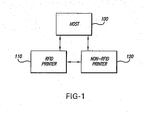
- FIGURE 1 is a block diagram representing a system in accordance with one embodiment of the present invention.
- FIGURE 1 shows a host 100, a Radio Frequency Identification (RFID) printer 110 and a non-RFID printer 120.
- the host 100 can be a computer mainframe, a personal computer, a workstation, a network server, a barcode scanner/terminal or any other data input device.
- the RFID printer 110 is illustratively loaded with, and capable of printing to, record members such as, but not limited to, labels, tags, tickets, forms, signs, or like media samples.
- the record members that are produced by the RFID printer 110 have embedded therein a RFID transponder that is capable of being programmed, via a radio frequency (RF) signal, to store various types of data.
- RF radio frequency
- RFID transponders are known in the art and typically comprise an integrated circuit chip and a radio frequency antenna.
- the RFID integrated circuit typically includes a read-only memory (ROM) that stores a unique identification number identifying the RFID transponder.
- the RFID integrated circuit typically also includes a memory or registers that are programmable to store various types of data.
- RFID transponders can be programmed to store any type of information, and are commonly employed to store data relating to a product or a package to which the associated record member is to be affixed, including, but not limited to, information pertaining to the nature of the product or the contents of the package, quantity information, price information, etc.
- the RFID printer 110 is thus capable of being loaded with a web of record members (for example, a roll of RFID labels) that have RFID transponders embedded thereon.
- the RFID printer 110 is capable of both printing on said record members and programming, via a RF signal, the RFID transponders.
- the non-RFID printer 120 is illustratively a printer that is capable of printing record members, such as, but not limited to, labels, tags, tickets, forms, signs, or like media samples. According to an illustrative embodiment of the present invention, the non-RFID printer 120 is loaded with a web of record members (for example, a roll of labels) that do not have RFID transponders thereon and are, thus, free of RFID transponders.
- a web of record members for example, a roll of labels
- the host 100 provides input data to the RFID printer 110.
- the input data provided to the RFID printer 110 may include data that is intended for a RFID record member or may alternatively include data that is intended for a non-RFID record member (that is, a conventional record member that does not have a RFID transponder thereon).
- Data that is intended for a RFID record member will include data that is to be written to the RFID transponder on an associated record member, and may also include data that is to be printed on the associated record member.
- Data that is intended for a non-RFID record member will include data that is to be printed on a record member and will not include RFID data to be encoded in a RFID transponder.
- the RFID printer 110 is capable of determining whether the data provided by the host 100 is intended for a RFID printer or for a non-RFID printer, that is, the RFID printer 110 determines whether the received data includes RFID data or not. If the received data does include RFID data, the RFID printer produces a RFID record member according to the received data. Thus, the RFID printer 110 will encode a RFID transponder associated with a given record member in the web of record members, and, if the received data further includes data that is to be printed on the associated record member, will print said data on the associated record member.
- the RFID printer 110 determines that the data provided by the host 100 is not intended for a RFID printer (that is, if the received data does not include RFID data)
- the RFID printer 110 transmits the received data to the non-RFID printer 120.
- the non-RFID printer 120 then prints the received data on a non-RFID record member.
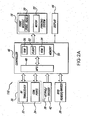
- FIGURE 2A is a block diagram representing a RFID printer, such as RFID printer 110, according to an illustrative embodiment of the present invention.
- the RFID printer 110 illustratively includes a printing system 18 with a print head such as a thermal print head 20 or the like.
- the printing system 18 also includes a motor 22 that moves a web of record members 24, such as labels, tags, etc., via for example one or more rollers (not shown) past the print head 20 in order to print data thereon.
- Data printed by the print head 20 can include barcode and/or alpha-numeric information.
- the RFID printer 110 includes a number of input devices mounted in its housing. These input devices include a communication interface 30 and a keypad 38.
- the communication interface 30 includes a radio frequency transceiver 32 and/or one or more communication ports 34 such as an RS 232 port, a serial port, a parallel port, an 802.11b port, an 802.3 port, a USB port, etc.
- the communication interface 30 allows the RFID printer 110 to communicate with a host device, such as host 100, to receive data therefrom or to transmit transaction data thereto.
- the communication interface 30 allows the RFID printer 110 to communicate with the host in real time.
- the RFID printer 110 may be operated off-line such that the data received from a host is stored in a look-up table or the like in a memory of the printer for later use. Similarly, data can be entered via one or more of the input devices, stored in a memory of the printer and later transmitted with a batch of data records to a host via a communication port 34.
- the RFID printer 110 is couplable to non-RFID printer 120 through the communication interface 30. In various embodiments, the RFID printer 110 can communicate with the non-RFID printer 120 by way of the radio frequency transceiver 32 or one of the communication ports 34.
- the RFID 110 printer receives print data that is intended for a non-RFID printer, that is, print data that does not include RFID data, the RFID printer 110 forwards such data to the non-RFID printer 120 for printing via the communication interface 30.
- the RFID printer 110 includes a RFID reader/writer 36.
- the RFID reader/writer 36 is capable of reading and/or writing to a RFID transponder on a record member that is driven by the motor 22 of the printer 110.
- the RFID reader/writer 36 forms one of the data input devices for the RFID printer 110.
- the RFID reader/writer 36 forms one of the output devices along with the printing system 18 and the communication interface 30 when transmitting or sending data out from the printer 110.
- the RFID printer 110 includes a plurality of keys 38.
- the keys 38 include a keypad with keys and a trigger key 42.
- the keypad may be utilized to enter alpha-numeric data to the printer 110.
- the keypad may have only a limited number of keys that are actuable in accordance with information depicted on a display 44 for selecting a number of operations of the printer, for example, feeding a web of record members through the printer 110, displaying status information, etc.
- the trigger key 42 may be actuable by a user in various modes of the printer 110 to actuate the printing system 18 and/or the RFID reader/writer 36.
- one or more of these devices can be actuated automatically by a controller 46 of the printer 110 in accordance with a stored application program.
- the display 44 may also be controlled to provide prompts to the user to actuate the trigger key 42 and/or other keys so as to control various operations of the printer 110.
- the RFID printer 110 includes a controller 46 that includes a microprocessor 48 and a memory 50.
- the memory 50 includes non-volatile memory such as flash memory 52 and/or a ROM 54 such as the EEPROM.
- the memory 50 also includes a RAM 56 for storing and manipulating data.
- the microprocessor 48 controls the operations of the printer 110 in accordance with an application program that is stored in the flash memory 52.
- the microprocessor 48 may operate directly in accordance with the application program.
- the microprocessor 48 can operate indirectly in accordance with the application program as interpreted by an interpreter program stored in the memory 54 or another area of the flash memory 52.
- the microprocessor 48 is operable to select an input device 32, 34, or 38 to receive data therefrom and to manipulate the received data and/or combine it with data received from a different input source in accordance with a stored application program.
- the microprocessor 48 couples the selected, combined and/or manipulated data to the printing system 18 for printing on a record member.
- the microprocessor 48 may select the related data to be written to a RFID transponder on a record member.
- the microprocessor couples the data selected for writing to the RFID reader/writer 36 wherein the data is written in encoded form to the RFID transponder.
- the microprocessor 48 can select the same or different data for storage in a transaction record in the RAM 56 and for uploading via the communication interface 30 to a host 100.
- the processor 48 is operable to select data to be coupled to the printing system 18 independently of the data that the processor 48 selects to be coupled to the RFID reader/writer 36 to provide a high degree of flexibility.
- the controller 46 receives data that is to be printed on a record member.
- This data can be received from any of input devices 30 and 38.
- such received data may include RFID data that is to be encoded to a RFID transponder associated with a record member.
- this data may not include any RFID data, but rather comprises only data that is to be printed on a conventional, non-RFID, record member.
- the controller 46 determines whether the received data includes RFID data.
- the input data stream contains markers that indicate whether the input data comprises RFID data and these markers are used by the controller 46 to determine what to do with the input data.
- the controller 46 controls the RFID encoder 36 to encode the received RFID data in a RFID transponder disposed on a record member in the web of record members. If the received data does not include RFID data, the controller transmits the received data to a second printer, such as non-RFID printer 120, for printing, illustratively via communication interface 30.
- a second printer such as non-RFID printer 120
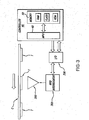
- the RFID reader/writer 36 includes a radio frequency antenna 300, a RFID interrogator 302 and an input/output interface 306.
- the RFID antenna 300 illustratively radiates energy in a narrow beam towards an adjacent RFID transponder T that is aligned with the antenna 300.
- the RFID antenna 300 radiates energy in response to a RFID module or interrogator 302 in order to write to, or program, the adjacent RFID transponder.
- the RFID interrogator 602 is responsive to the controller 46 to drive the antenna 300 to write or program particular information into the adjacent RFID transponder T.
- the interrogator 302 is also responsive to energy picked up by the antenna 300 from the RFID transponder T to read information stored on the transponder T.
- the RFID interrogator 302 is coupled to the controller 46 by a RFID input/output interface 306, the interrogator 302 receiving or sending communication signals through the interface 306, and the interrogator 302 receiving power via the interface 306.
- the microprocessor 48 controls the printing system 18 of the RFID printer 110 to write to and/or read a RFID transponder T in a label and to print on that same label as follows with respect to FIGURES 4A and 4B .
- the microprocessor 48 controls the printer motor 22 to feed a label to the top of form position at which point the movement of the label web is stopped.
- the RFID transponder T will be generally aligned with the antenna 300.
- the microprocessor 48 retrieves data from the memory 50 that has been sent from the host 100, or otherwise received from one of the data input devices 30 or 38, for writing to the RFID transponder.
- This data may be for example electronic product code (EPC) information or other data.
- EPC electronic product code
- the microprocessor 46 generates a program command.
- the program command is a packet of control information to be sent to the RFID interrogator or module 302.
- the microprocessor 48 proceeds to block 426 to send the generated packet to the RFID module, i.e. interrogator 602.
- the RFID module or interrogator 302 includes its own microprocessor.
- the RFID module performs a number of functions. For example, the module 302 determines whether a RFID transponder is within its field by reading the RFID transponder's identification code.
- the RFID module 302 as instructed by the controller 46 erases the data stored in the RFID transponder, verifies the erasure and then programs the RFID data received from the microprocessor 48 into the RFID transponder.
- the RFID module 302 also verifies that the data has been programmed into the RFID transponder by reading the data stored in the transponder after a programming operation to verify that the data was correctly written into the RFID transponder. Upon completing the verification process, the RFID module 302 generates a response packet that is transmitted back to the microprocessor 48.
- the microprocessor 48 receives the response packet from the RFID module 302, and at block 630, the microprocessor 48 extracts data from the response packet.
- the data in the response packet may include a code representing the successful programming of the RFID transponder or the data may include a code representing a particular error.
- the response data may include an error code indicating that the RFID module could not read a RFID tag, or a code indicating that the tag could not be erased or a code indicating that the tag was not accurately programmed.
- the microprocessor 48 decodes the data in the response packet to determine at block 434 whether the programming of the RFID transponder was successful or whether the response packet from the RFID module included an error code. If the programming of the RFID transponder was determined to be successful, that is, without error, at block 434, the microprocessor 48 proceeds to block 436 to control the feeding or movement of the web and the printing of data on the label via the print head. It is noted that, in an illustrative embodiment, while the RFID transponder is being read from or programmed, the web is stationary.
- the microprocessor 608 moves the web past the print head: If the microprocessor 48 determines at block 434 that the response packet received from the RFID module indicated an error condition, the microprocessor 48 proceeds to block 438 to display an error message on the display 44 of the printer 110. From block 438, the microprocessor proceeds to block 440 to feed the label with the defective RFID transponder past the print head and controls the print head to print an overstrike image, such as evenly spaced longitudinally extending bars, on the record member RM. This indicates that the RFID transponder is defective. From blocks 438 or 440, the microprocessor proceeds to block 408 to feed the next label to the top of form position at block 420 as discussed above.
- FIGURE 5 shows a RFID printer, generally indicated at 540, in accordance with an illustrative embodiment of the present invention.
- the printer 540 can be essentially the same as the RFID printer disclosed in U.S. patent application 10/873,979 the disclosure of which is incorporated herein by reference, except as otherwise disclosed herein. It is noted that application 10/873,979 incorporates the disclosure of U.S. Patent 5,838,377 .
- the invention is illustrated in connection with a thermal printer using dot heating elements to create images such as bar codes, graphics, alpha numeric characters and the like, the invention is also useful with printers such as ink jet, laser, xerographic, impact, and other types of printers.
- the printer 540 which corresponds to the printer 40 in patent application 10/873,979, has a generally vertical frame panel 571 and a conductive metal horizontal frame member 572 on a conductive metal base plate 520.
- a movable mounting member 556 is pivotally mounted to the frame plate 571 about hinge blocks 573 (only one of which is shown in FIGURE 5 ).
- a roll mounting member 550 is shown to mount a roll R of a web C of record members RM.
- the record members RM are illustrated to comprise a composite label web C which comprises a longitudinally extending carrier web W to which a series of pressure sensitive labels L are releasably adhered by pressure sensitive, tacky, adhesive A ( FIGURES 5 and 6 ).
- the web of record members RM can be comprised of a web of tags or forms.
- the web C is shown to be paid out of the roll R and passes beneath a guide roller 562' rotatably mounted by a bracket 562" to a guide member 560 which is part of a web guide generally indicated at 562.
- Any suitable web guide for example, just a member with a curved surface or a roller can be used instead, if desired.
- From there the web C passes between a thermal print head 569 which is part of a print head assembly 570 and a platen roll 563. It is noted the web C extends from the roll R to a position upstream of the nip of the print head 569 and the platen roll 563 and extends downstream beyond the nip.
- the platen roll 563 is shown to have a conductive metal shaft 506 about which a tubular elastomeric sleeve 506' is received as shown in FIGURE 7 for example.
- the shaft 506 acts as a RF reflector. If desired, the shaft 506 can be made of a rigid plastics material which is not RF reflective.
- a delaminator in the form of a peel bar 564' is provided downstream and preferably adjacent the nip. However, the delaminator can alternatively comprise a peel roller.
- a label L can be delaminated at the delaminator 564' when the web W is advanced by a motor 665 between a motor-driven roll 565 and a back-up roll 566.
- a spring 566' is used to urge the backup roll 566 toward the roll 565 so that the web W is pressed between the rolls 565 and 566. From there the carrier web W passes about an arcuate guide plate 670 and through an exit opening 549 of a movable panel 548.
- the illustrated printer 540 utilizes an ink ribbon IR wound into a supply roll SR.
- the supply roll SR has a core 552 and the core 552 is mounted on a spindle 553.
- the ink ribbon IR is paid out of the supply roll SR and passes beneath a ribbon guide 557 to the nip between the print head 569 and the platen roll 563 and from there the ink ribbon IR passes partially about a guide 558 and onto a take-up roll TR.
- the take-up roll TR has a core 554 identical to the core 552.
- the core 554 is mounted on a spindle 555 identical to the spindle 553. Except for the delaminator 564', the roll 562' and the bracket 562" the foregoing describes the printer 540 disclosed in U.S. patent 5,833,377 .
- each of the record members R includes a RFID transponder T incorporated in a composite web C of labels L as best shown in FIGURE 6 .
- a typical transponder includes an integrated circuit chip and an antenna.
- the roll R includes RFID labels L.
- Each label L is illustrated to have a RFID transponder T adhered to the adhesive A on the underside of the label L.
- the composite label web C has a RFID transponder T sandwiched between the label L and the carrier web W.
- the RFID transponder T in a preferred embodiment is a passive transponder that uses received RF energy to power the chip of the transponder T and enabling functions of reading and/or writing when sufficient energy is received by the transponder T so that information can be read or written to, i.e., programmed into, the RFID transponder.
- the pitch of the transponders T is considered the distance from the centerline of one transponder to the centerline of an immediately adjacent transponder.
- the pitch or length of a record member RM is the distance from the leading edge of one record member RM to the leading of an adjacent record member RM in the longitudinal direction of the web.
- FIGURE 5 also shows an antenna assembly 500 fitted between the web guide 562 and the platen roll 563.
- a shield or RF reflector generally indicated at 501 extends into contact with an electrically conductive metal delaminator in the form of a peel edge 564' which forms part of the shield.
- the shield 501 which is preferably comprised of conductive metal such as steel, has an inclined portion 503 ( FIGURE 7 ), a downwardly extending portion 502 joined to the inclined portion 503, a downwardly extending portion 504 and a base portion 505 grounded to the frame 520.
- the motor 665 is below the inclined portion and above the base portion 505.
- the platen roll 563 is above the inclined portion 503.
- the inclined portion 503 of the shield 501 supports the antenna assembly 500 so that a plane of antenna 500' is perpendicular to a RFID transponder T adjacent the antenna 500'.
- the second portion 502 of the shield 501 extends at an angle from the support portion 503 and towards the web C so that a part of the shield 501 is adjacent the web C to shield a RFID transponder in an adjacent record member RM that is downstream of the shield 501, i.e., a record member RM that is past the shield 501 in the direction of web movement, from energy radiated from the antenna 500'.
- the second portion 502 of the shield 501 is formed integrally with the portion 503 supporting the antenna 500'.
- the second shield portion 502 may include multiple parts.
- the portion of the shield 501 adjacent to the web includes an electrically conductive metal web guide 510 with a downwardly extending portion 511 that abuts and makes intimate electrical contact with shield portion 502.
- the portion of the shield 501 adjacent the web C may also include the delaminator 564' as discussed below.
- the platen roll 563 is shown to have a conductive steel shaft 506 which reflects radiation from the antenna assembly 500.
- the antenna assembly 500 includes a nonconducting bracket or holder 507 which is secured to the shield portion 503 by two thumb screws 508 (only one of which is shown) threaded into the holder 507.
- the screws 508 pass through laterally spaced elongate slots 509 in the inclined shield portion 503.
- the slots 509 allow the position of the antenna assembly 500 to be adjusted.
- the slope of the inclined shield portion 503 is parallel to the path of the web C at the read and/or write station where a transponder T is read and/or written to. Movement of the antenna assembly 500 allows optimal alignment of the antenna 500' with RFID transponders T on the composite web C.
- the delaminator 64' and the guide form part of the shield 501.
- the shelf or web guide 510 has a downwardly extending portion 511 which is welded to the delaminator 564'.
- the delaminator 564' and the guide 510 are preferably composed of steel.
- the shield 501, the delaminator 564' and the guide 510 provide effective shielding of the energy radiated from the antenna assembly 500 and from a RFID transponder which is downstream of the shield 501, the guide 510 and the delaminator 564'.
- one of the RFID transponders T is spaced from but is adjacent to the antenna assembly 500. Therefore, the antenna 500' does not affect the RFID transponder T which is beyond the delaminator 564'.
- FIGURE 7 shows the antenna assembly 500 to be located at a write and/or read station.
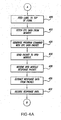
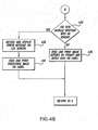
- FIG. 8 is a flowchart representing a method of printing RFID record members according to an illustrative embodiment of the present invention.
- print data and associated print job parameters are received at a printer, such as RFID printer 110, capable of printing labels that have RFID transponders embedded thereon and capable of programming said RFID transponder.
- a printer such as RFID printer 110
- such data is received via input devices such as communication interface 30 or keypad 38.
- the RFID printer prints the label (step 820) and programs the RFID transponder (step 830). If the received data does not include RFID data, the RFID printer transmits the data to a second printer, such as non-RFID printer 120, that is configured to print non-RFID record members, that is, record members that do not have a RFID transponder embedded thereon, which printer then proceeds to print the non-RFID record label, as shown by step 840.
- the RFID printer 110 determines whether the print job is done at step 850. If the print job is done, the process is complete. If the print job is not done, then the controller 46 executes instructions to loop to step 810 to process the received data intended for the next record member.
- the host 100 provides input data to the non-RFID printer 120.
- This input data provided to the non-RFID printer 120 may include data that is intended for a RFID record member or may instead include data that is intended for a non-RFID record member (that is, a conventional record member that does not have a RFID transponder embedded thereon).
- Data that is intended for a RFID record member will include data that is to be encoded to the RFID transponder embedded in an associated record member, and may also include data that is to be printed on the associated record member.
- Data that is intended for a non-RFID record member will include data that is to be printed on a record member and will not include RFID data to be encoded in a RFID transponder.
- the non-RFID printer 120 is capable of determining whether the data provided by the host 100 is intended for a RFID printer or for a non-RFID printer, that is, words, the non-RFID printer 120 determines whether the received data includes RFID data or not. If the received data does include RFID data, the non-RFID printer 120 transmits the received data to the RFID printer 110. The RFID printer 110 then produces a RFID record member according to the received data. Thus, the RFID printer 110 will encode a RFID transponder associated with a given record member in the web of record members, and, if the received data further includes data that is to be printed on the associated record member, will print said data on the associated record member.
- the non-RFID printer 110 determines that the data provided by the host 100 is not intended for a RFID printer (that is, if the received data does not include RFID data)
- the non-RFID printer 120 then prints the received data on a non-RFID record member.
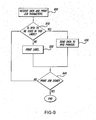
- FIGURE 9 is a flowchart representing a method of printing RFID record members according to this alternative embodiment of the present invention.
- print data and associated print job parameters are received at a printer, such as non-RFID printer 110, configured to print record members that do not have RFID transponders embedded thereon.
- data is received via input devices such as a communication interface 30 or keypad 38.
- the non-RFID printer transmits the data to a second printer, such as RFID printer 110, that is configured to print RFID record members and to program the RFID transponder embedded thereon, which printer then proceeds to print the RFID record label and encode the associated RFID transponder, as shown at step 930.
- a second printer such as RFID printer 110, that is configured to print RFID record members and to program the RFID transponder embedded thereon, which printer then proceeds to print the RFID record label and encode the associated RFID transponder, as shown at step 930.
- the non-RFID printer 120 determines whether the print job is done at step 940. If the print job is done, the process is complete. If the print job is not done, then the controller 46 executes instructions to loop to step 910 to process the received data intended for the next record member.
- either of the RFID printer 110 and the non-RFID 120 can receive input data from the host 100, or one of input devices 30 and 38.
- This input data provided to the non-RFID printer 120 may include data that is intended for a RFID record member or may instead include data that is intended for a non-RFID record member (that is, a conventional record member that does not have a RFID transponder embedded thereon).
- Data that is intended for a RFID record member will include data that is to be encoded to the RFID transponder embedded in an associated record member, and may also include data that is to be printed on the associated record member.
- Data that is intended for a non-RFID record member will include data that is to be printed on a record member and will not include RFID data to be encoded in a RFID transponder.
- both the RFID printer 110 and the non-RFID printer 120 are capable of determining whether the data provided by the host 100 is intended for a RFID printer or for a non-RFID printer.
- the printer that receives the input data determines whether the received data includes RFID data or not. If the non-RFID printer 120 receives input data, it determines whether or not the received data includes RFID data. If the received data does include RFID data, the non-RFID printer 120 transmits the received data to the RFID printer 110. The RFID printer 110 then produces a RFID record member according to the received data.
- the RFID printer 110 will encode a RFID transponder associated with a given record member in the web of record members, and, if the received data further includes data that is to be printed on the associated record member, will print said data on the associated record member. If, on the other hand, the non-RFID printer 110 determines that the data provided by the host 100 is not intended for a RFID printer (that is, if the received data does not include RFID data), the non-RFID printer 120 then prints the received data on a non-RFID record member.
- FIGURE 2B is a block diagram representing a non-RFID printer, such as non-RFID printer 120, according to an illustrative embodiment of the present invention.
- a typical non-RFID printer usable in and with the present invention is essentially as disclosed in U.S. patent 5,833,377 , except as noted herein, the disclosure of which is incorporated by reference.
- the non-RFID printer 120 illustratively includes a printing system 18' with a print head such as a thermal print head 20' or the like.
- the printing system 18' also includes a motor 22' that drives a web of record members 1202 ( FIGURE 12 ) such as labels, tags, packing slips, etc., via one or more rollers (not shown) past the print head 20' in order to print data thereon.
- Data printed by the print head 20' can include barcode and/or alpha-numeric information.
- the non-RFID printer 120 includes a number of input devices mounted in its housing. These input devices include a communication interface 30' and a keypad 38'.
- the communication interface 30' includes a radio frequency transceiver 32' and/or one or more communication ports 34' such as an RS 232 port, a serial port, a parallel port, an 802.11b port, an 802.3 port, a USB port, etc.
- the communication interface 30' allows the non-RFID printer 120 to communicate with a host device, such as host 100, to receive data therefrom or to transmit transaction data thereto.
- the communication interface 30' allows the non-RFID printer 120 to communicate with the host in real time.
- the non-RFID printer 120 may be operated off-line such that the data received from a host is stored in a look-up table or the like in a memory of the printer for later use. Similarly, data can be entered via one or more of the input devices, stored in a memory of the printer and later transmitted with a batch of data records to a host via a communication port 34'.
- the non-RFID printer 120 is couplable to RFID printer 110 through the communication interface 30'.
- the non-RFID printer 120 can communicate with the RFID printer 110 by way of the radio frequency transceiver 32' or one of the communication ports 34'.
- the non-RFID printer 120 if the non-RFID printer 120 receives print data that is intended for a RFID printer, that is, print data that includes RFID data, the non-RFID printer 120 forwards such data to the RFID printer 110 for printing via the communication interface 30'.
- the non-RFID printer 120 includes a plurality of keys 38'.
- the keys 38' include a keypad and a trigger key.
- the keypad may be utilized to enter alpha-numeric data to the printer 120.
- the keypad may have only a limited number of keys that are actuable in accordance with information depicted on a display 44' for selecting a number of operations of the printer, for example, feeding a web of record members through the printer 120, displaying status information, etc.
- the trigger key may be actuable by a user in various modes of the printer 120 to actuate the printing system 18'.
- one or more of these devices can be actuated automatically by a controller 46' of the printer 120 in accordance with a stored application program.
- the display 44' may also be controlled to provide prompts to the user to actuate the trigger key and/or other keys so as to control various operations of the printer 120.
- the non-RFID printer 120 includes a controller 46' that includes a microprocessor 48' and a memory 50'.
- the memory 50' includes non-volatile memory such as flash memory 52' and/or a ROM 54' such as the EEPROM.
- the memory 50' also includes a RAM 56' for storing and manipulating data.
- the microprocessor 48' controls the operations of the non-RFID printer 120 in accordance with an application program that is stored in the flash memory 52'.
- the microprocessor 48' may operate directly in accordance with the application program. Alternatively, the microprocessor 48' can operate indirectly in accordance with the application program as interpreted by an interpreter program stored in the memory 54' or another area of the flash memory 52'.
- the microprocessor 48' is operable to select an input device 32', 34' or 38' to receive data therefrom and to manipulate the received data and/or combine it with data received from a different input source in accordance with a stored application program.
- the microprocessor 48' couples the selected, combined and/or manipulated data to the printing system 18' for printing on a record member.
- the microprocessor 48' can select the same or different data for storage in a transaction record in the RAM 56' and for uploading via the communication interface 30' to a host 100.
- the controller 46' receives data that is to be printed on a record member. This data can be received from either of input devices 30' and 38'. In some instances, such received data may include RFID data that is to be encoded to a RFID transponder associated with a record member. In other instances, this data may not include any RFID data, but rather comprise only data that is to be printed on a conventional non-RFID record member. According to one embodiment of the present invention, the controller 46' determines whether the received data includes RFID data. In an illustrative embodiment, the input data stream contains markers that indicate whether the input data comprises RFID data and these markers are used by the controller 46' to determine what to do with the input data.
- the controller 46' transmits the received data to a second printer, such as RFID printer 110, for printing, illustratively via communication interface 30'. If the received data does not include RFID data, the controller 46' controls the printing system 18' to print the data on a record member in the web of record members.
- the RFID printer 110 determines whether or not the received data includes RFID data. If the received data does not include RFID data, the RFID printer 110 transmits the received data to the non-RFID printer 120. The non-RFID printer 120 then prints the received data on a non-RFID record member. If, on the other hand, the RFID printer 110 determines that the data provided by the host 100 is intended for a RFID printer (that is, if the received data includes RFID data), the RFID printer 110 then produces a RFID record member according to the received data. Thus, the RFID printer 110 will encode a RFID transponder associated with a given record member in the web of record members, and, if the received data further includes data that is to be printed on the associated record member, will print said data on the associated record member.
- a system analogous to the system of FIGURE 1 is implemented with one printer instead of two.
- the printer is a dual mode RFID printer that is illustratively configured in the same way as the RFID printer shown in FIGURE 2A , except for the fact that the printer is capable of holding two separate webs of record members.
- One of the webs comprises record members that have RFID transponders embedded thereon and another web comprises "conventional" record members that do not have RFID transponders embedded thereon.
- the printer includes a RFID reader/writer that is capable of encoding the RFID transponders disposed on the web that comprises RFID record members.
- the host 100 or one of the input devices 30 or 38, provides input data to the dual mode printer.
- the input data provided to the dual mode printer may include data that is intended for a RFID record member or may alternatively include data that is intended for a non-RFID record member (that is, a conventional record member that does not have a RFID transponder thereon).
- Data that is intended for a RFID record member will include data that is to be encoded to the RFID transponder in an associated record member, and may also include data that is to be printed on the associated record member.
- Data that is intended for a non-RFID record member will include data that is to be printed on a record member and will not include RFID data to be encoded in a RFID transponder.
- the dual mode printer is capable of determining whether the data provided by the host 100 is intended for a RFID record member or for a non-RFID record member. In other words, the dual mode printer determines whether the received data includes RFID data or not. If the received data does include RFID data, the dual mode printer processes the job employing the web contained therein which comprises RFID record members, thereby producing a RFID record member according to the received data. Thus, the dual mode printer will encode a RFID transponder associated with a given record member in the web of RFID record members, and, if the received data further includes data that is to be printed on the associated record member, will print said data on the associated RFID record member.
- the dual mode printer determines that the data provided by the host 100 is not intended for a RFID record member (that is, if the received data does not include RFID data)
- the dual mode printer prints the received data on a non-RFID record member contained in the web of non-RFID record members.
- FIGURE 10 illustrates a printer with a pair of rolls R1 and R2 of respective composite label webs W1 and W2, according to an exemplary embodiment of a dual mode printer of the present invention.
- the rolls R1 and R2 have respective cores, with core C2 being visible in FIGURE 10 .
- coreless rolls can be used.
- the web W1 has labels L1 releasably adhered by pressure sensitive adhesive to a flexible carrier web CW1
- the web W2 has labels L2 releasably adhered by pressure sensitive adhesive A to a flexible carrier web CW2.
- the webs W1 and W2 of rolls R1 and R2 are identical except that one of the webs comprises RFID record members, each record member having a RFID transponder disposed thereon, while the other web comprises "conventional," non-RFID, record members.
- the labels L1 can be RFID labels and the labels L2 can be non-RFID labels.
- FIGURE 10 illustrates the label web W2 as being threaded along a path having a center line CL2 from the roll R2 to between a print head 1058 and a platen roll 1074.
- the print head 1058 is illustrated to be a thermal print head having a straight line of individual or dot heating elements, however, other types of print heads can be used instead.
- the print head 1058 is shown to be elongate and essentially fixed in place or stationary except the print head 1058 is resiliently mounted with respect to the platen roll 1074.
- the web W1 is shown extending outwardly away from the roll R1 by the phantom lines PL' because only one web W1 or W2 at a time is threaded to pass between the print head 1058 and the platen roll 1074.
- the web W1 were threaded to pass along a path as shown in FIGURE 1 by phantom lines PL', the web W2 would remain on the roll R2 and would not be threaded between the print head 1058 and the platen roll 1074.
- the centerline of the path for the web W1 is shown to be CL1.
- the centerlines CL1 and CL2 pass through longitudinally spaced registration marks 1000 on the webs W1 and W2, there being one registration mark 1000 per label.
- the web W2 is shown in FIGURE 10 with a U-shaped bend to expose the registration marks 1000.
- the rolls R1 and R2 are preferably disposed in side-by-side relationship as shown, and also the rolls R1 and R2 are preferably disposed on a common axis A1, although other relationships and dispositions can be used.
- the webs W1 and W2 and their center lines CL1 and CL2 are shown to be parallel.
- the webs W1 and W2 can move longitudinally in label paths that extend between the elongate transversely extending print head 1058 and the platen roll 1074.
- the web W1 would be printed by only that portion 1058(1) of the print head 1058 which lies along the label web path of the label web W1, and likewise the web W2 would be printed by only that portion 1058(2) of the print head 1058 which lies along the label path of the label web W2.
- the printer of FIGURE 10 has a RFID system as disclosed in FIGURE 3 for reading from or writing to a transponder T in the web W1, but in other respects, the printer is the same as disclosed in U.S. Patent Application Serial No. 10/640,071, filed August 13, 2003 , except as noted herein the disclosure of which patent application is incorporated by reference.
- the printer that receives the data to be printed and/or encoded to RFID transponders coordinates the printing of the RFID record members and the non-RFID record members is further operable to coordinate the printing such that identifying indicia such as sequential numbers are printed to both the printed RFID record members and the printed non-RFID record members.
- the controller 46 of the RFID printer 110 is operable to control the print head 20 of the RFID printer 110, and to provide instructions to the non-RFID printer 120, such that for example sequential numbers are printed on record members by the print head 20 of the RFID printer 110 and by the non-RFID printer 120 in a sequence corresponding to a sequence that data to be printed is received by the controller 46.
- the controller 46 of the non-RFID printer 120 is operable to control the print head 20 of the non-RFID printer 120, and to provide instructions to the RFID printer 110, such that sequential numbers are printed on record members by the print head 20 and by the RFID printer 110 in a sequence corresponding to a sequence that data to be printed is received by the controller 46.
- the controller 46 of the dual mode printer is operable to control the print head 20 such that sequential numbers are printed on both RFID and non-RFID record members in a sequence corresponding to the sequence that data to be printed is received by the controller 46.
- Printing of both the data and the associating indicia are preferably done at the same time, namely, the data are printed on the RFID record members of the RFID web while the web is advancing, and data are printed on the non-RFID record members of the non-RFID web while the web is advancing. Even if a printer is used in which the RFID web and/or the non-RFID web are stationary during printing, the data and the associating indicia are nevertheless preferably printed at the same time or substantially simultaneously or simultaneously. It is not required that the RFID printer and the non-RFID printer print at the same time. Recitation of a step for printing data and a step for printing associating indicia in any claim is not intended to limit the invention to the interpretation that the printing of data and associating indicia are performed separately or are separate steps.
- FIGURE 11 is a functional block diagram representing an alternative embodiment of the.present invention, wherein a separate controller 105 receives the input data stream from host 100 and selectively directs the input data to either the RFID printer 110 or the non-RFID printer 120.
- the controller 105 is a box having communication ports via which the controller is couplable to RFID printer 110 and non-RFID printer 120. If the controller 105 determines that received data includes RFID data to be encoded to a RFID transponder disposed on a record member, the controller directs that data to the RFID printer 110, which proceeds to encode said RFID data to a RFID transponder disposed on a record member.
- the RFID printer 110 prints such data to the associated record member: If the controller 105 determines that received data does not include RFID data to be encoded to a RFID transponder disposed on a record member, the controller directs that data to the non-RFID printer 120, which proceeds to print a record member in accordance with the received input data.
- the controller 105 provides instructions to the RFID printer 110 and the non-RFID printer 120. Said instructions instruct the RFID printer 110 and the non-RFID printer 120 to print sequential numbers on their respective record members in a sequence in which input data is received by the controller. In accordance with these instructions, the RFID printer 110 and the non-RFID printer 120 print sequential numbers on their respective record members in the sequence indicated by the controller 105.
- the RFID printer 110 and the non-RFID printer 120 are both capable of printing associating indicia on their respective members.
- these associating indicia associate record members printed by the RFID printer 110 with record members printed by the non-RFID printer 120.
- the associating indicia comprise numbers that associate record members printed by the RFID printer 110 with record members printed by the non-RFID printer 120.
- the associating indicia can comprise graphical symbols other than numbers.
- FIGURE 12 demonstrates this aspect of the present invention.
- FIGURE 12 shows RFID printer 110 and non-RFID printer 120.
- RFID printer 110 produces a web 1201 of record members 1203-1218.
- Non-RFID printer produces a web 1202 of record members 1219-1234.
- the record members 1203-1218 of the web 1201 produced by the RFID printer 110 have RFID transponders 1240 thereon.
- the RID transponders 1240 are only labeled as such for record members 1215 and 1216, but FIGURE 12 shows that the other record members 1203-1214, 1217,1218 also include RFID transponders.
- the record members produced by the RFID printer 110 and the non-RFID printer 120 include data 1250 that is printed on the record members by the printers 110 and 120. In FIGURE 12 this data is shown as bar code data, but the printed data 1250 can include any form of data.
- the bar code data 1250 are only labeled as such for record members 1211 and 1212, but FIGURE 12 shows that the other record members 1203-1210, 1213-1234 also include bar code data.
- the record members produced by the RFID printer 110 and the non-RFID printer 120 include indicia that associate certain record members printed by the RFID printer 110 with certain record members that are printed by the non-RFID printer 120.
- the associating indicia are numbers, in particular, sequential numbers shown printed in, for example, the upper right corner of each record member.
- FIGURE 12 there are certain sets of record members printed by the RFID printer 110 that include the same data (in this case, the same bar codes).
- record members 1215, 1216, 1217 and 1218 each have the same bar code printed thereon.
- These four record members make up a set of record members that is indicated in FIGURE 12 as set 1,1.
- This set designation refers to the first set of record members produced by the RFID printer 110.
- set 2,1 refers to the second set produced by the RFID printer 110, which set consists solely of record member 1214:
- Set 3,1 refers to the third set produced by the RFID printer 110 (comprising record members 1212 and 1213), and so on.
- the RFID printer 110 prints a unique indicium, namely the number 5, on each of the record members 1215-1218 of set 1,1. Similarly, the RFID printer 110 prints a number 6, on the sole record member 1219 of set 2,1. The RFID printer 110 prints a number 7 on each of the record members 1212 and 1213 of set 3,1, and other unique members such as 8, 9 and 10 on other sets through set 6.1, and so on.
- the term "related" indicium or indicia can alternatively include series of sequential numbers.
- Set 1,1 record members could bear indicia 1, 2, 3 and 4, and Set 1,2 record members could bear the same indicia 1, 2, 3 and 4;
- Set 2,1 record members could bear the indicium 5, and
- Set 2,2 record members could bear the indicium 5, and so on.
- Set 1,1 record members could bear indicia 1, 2, 3 and 4 and set 1,2 record members could bear the indicia 5, 6, 7 and 8;
- Set 2,1 record members could bear the indicium 9, and Set 2,2 record members could bear the indicia 10, 11, 12, and so on.
- the indicia are related in a significant way even though the indicia differ from each other.
- each set of record members in the web 1201 printed by the RFID printer 110 that include the same printed data have an associated set of record members that are printed by the non-RFID printer 120 and that include related printed data.
- the non-RFID printer 120 prints an indicium on the record members that it produces, associating each record member with its associated record members printed by the RFID printer 110.
- record members 1231-1234 each have the same bar code printed thereon as the record members 1215-1218 of set 1,1.
- These four record members 1231-1234 make up a set of record members that is indicated in FIGURE 12 as set 1,2. This set designation refers to the first set of record members produced by the non-RFID printer 120.
- set 2,1 refers to the second set produced by the non-RFID printer 120 (comprising record members 1228-1230), and so on.
- the non-RFID printer 120 prints the indicium, namely the number 5, on each of the record members 1231-1234 of set 1,2.
- This number 5 is the same indicium that is printed on the record members 1215-1218 of set 1,1 by the RFID printer 110, since, the record members of set 1,1 and 1,2 contain the related, in particular, the same printed data (e.g. bar codes as shown and/or other information).
- the non-RFID printer 120 prints the number 6 on each of the record members 1228-1230 of set 2,2, This number 6 is the same indicium that is printed on the record member 1214 set 2,1 by the RFID printer 110, since the record members of set 2,2 and 2,1 contain the same printed data (e.g. bar codes as shown and/or other information).
- the non-RFID printer 120 prints a unique indicium such as a number 7 on each of the record members 1225-1227 of set 3,2, and so on.
- the RFID printer 110 and non-RFID printer 120 print the associating indicia on only one record member of each set.
- the RFID printer 110 and non-RFID printer 120 print the associating indicia on the first record member of each set.
- the RFID printer 110 prints the associating indicia on only record members 1218, 1214, 1213, 1211, 1209 and 1206, and the non-RFLD printer prints the associating indicia on only record members 1234, 1230, 1227, 1224, 1222 and 1220.
- the associating indicia are printed on only the last record member of each set.
- the above described method and system of printing associating indicia on record members can be employed whether or not data such as bar code data are printed on the record members.
- FIGURE 13 is a flowchart representing a method of adding sequence numbers or other associating indicia to record members produced by the RFID printer 110 and the non-RFID printer 120. In an illustrative embodiment of the present invention, the steps shown in FIG.
- step 13 take place between blocks 800 and 810 in FIGURE 8 .
- print data and associated print job parameters are received at a printer, such as RFID printer 110 or non-RFID printer 120.
- data is received via input devices such as communication interface 30 or keypad 38.
- step 1310 it is determined whether associating indicia are to be added to a record member. If associating data are to be added, at step 1320, the white space is determined. At step 1330, a non-volatile sequential counter is incremented. At step 1340, the field is formatted. From there the printing process proceeds as shown at step 810 of FIGURE 8 . At step 1310, if it is determined that no associating indicium is to be added, the printing process proceeds as shown at step 810 of FIGURE 8 .
- RFID writer designates hardware and/or software that can at least write data into RFID transponders.
- RFID reader/writer designates hardware and/or software that can both write data to and read data from RFID transponders. Use of the term “RFID writer” herein does not exclude a RFID reader/writer which has both reading and writing capabilities.
- the disclosure includes the following:
- first and second printers there are first and second printers, and there is a communication port couplable to the second printer, and wherein if the received data does hot include RFID data, a controller transmits the received data to the second printer via the communication port.
- first and second printers There are first and second printers, and there is a controller operable to control a print head and to provide instructions to the second printer, such that sequential numbers are printed on record members by the print head and by the second printer in a sequence corresponding to a sequence that data to be printed is received by the controller.
- first and second printers wherein a controller is operable to control the first and second printers to print associating indicia on the first and second record members.
- the printer includes a print head, wherein the print head is located such that a first web can be advanced into printing cooperation with a first portion of the print head and a second web can be advanced into printing cooperation with a second portion of the print head.
- the controller is operable to control the print head such that sequential numbers are printed on record members in the first web and record members in the second web in a sequence corresponding to a sequence that data to be printed is received by the controller. Stated differently, the controller is operable to print associating indicia on the record members of the first and second webs.
- a controller controls the RFID writer to write the received RFID data to a RFID transponder disposed on a record member of the first web and controls a print head to print the printing data on said record member of the first web.
- the first printer comprises a communication port couplable to the second printer and the second printer comprises a communication port couplable to the first printer, and wherein if the received data does not include RFID data, a controller transmits the received data to the communication port of the second printer via the communication port of the first printer.
- a controller is operable to control a print head and to provide instructions to the second printer, such that sequential numbers are printed on record members by the print head and by the second printer in a sequence corresponding to a sequence that data to be printed is received by the controller.
- a controller is operable to control the first and second printers to print associating indicia on the first and second record members.
- the received data includes RFID data to be written to a RFID transponder and printing data to be printed on an associated record member, employing a printer to write the received RFID data to a RFID transponder disposed on a record member and to print the printing data on said record member.
- printing with a first printer, and providing instructions to a second printer to print, sequential numbers on record members in a sequence corresponding to a sequence that data to be printed is received by the controller.
- a communication port couplable to the second printer, and wherein if the received data does include RFID data, the controller transmits the received data to the second printer via the communication port.
- a controller is operable to control a print head, and to provide instructions to the second printer, such that sequential numbers are printed on record members by the print head and by the second printer in a sequence corresponding to a sequence that data to be printed is received by the controller.
- the controller controls both printers to print associating indica on the record members of the first and second printers.
- a first controller In or for a system with a first printer with a first print head and a second printer with a second print head, if the data received by a first controller includes RFID data to be written to a RFID transponder and printing data to be printed on an associated record member, the controller transmits the received data to a second printer and the second controller controls the RFID writer to write the received RFID data to a RFID transponder disposed on a record member of a second web and controls the second print head to print the printing data on said record member of the second web.
- the first printer further comprises a communication port couplable to the second printer and the second printer comprises a communication port couplable to the first printer, and wherein if the received data does include RFID data, the first controller transmits the received data to the communication port of the second printer via the communication port of the first printer.
- the first controller is operable to control the first print head, and to provide instructions to the second printer, such that sequential numbers are printed on record members by the first print head and by the second print head in a sequence corresponding to a sequence that data to be printed is received by the first controller.
Abstract
Description
-
U.S. Patent Application 10/873,979, filed June 22, 2004U.S. Patent Application 10/640,071, filed August 13, 2003 - The present invention relates to RFID (Radio Frequency Identification) printer systems, methods of printing and record members.
- The following prior art is made of Record:
U.S. Patent 5,833,377 ;U.S. Patent 6,327,972 ;U.S. Patent 6,481,907 ;U.S. Patent 6,677,852 ; andU.S. patent application 10/222,692, filed August 16, 20022004/0032443, published February 19, 2004 ; and Canadian patent2,178,773 . - RFID (Radio Frequency Identification) transponders have been embedded in record members such as tags, tickets, labels and the like to track inventory. The data contained in the transponder is typically read by a stationary RFID reader as the inventory with the RFID transponder is carried past the stationary reader on a conveyor belt or the like. Similarly, stationary RFID writers are typically used to write data into the RFID transponder. RFID printers are now required to be capable of both printing on record members, such as labels, tags, etc., and capable of writing to and/or reading from a RFID transponder contained on the record member.
-
U.S. Pat. No. 6,327,972 shows a stationary printer for writing data into a transponder embedded in a label and for printing data on the same label. The printer is connected to a computer via a conductor to receive the data to be printed on the label together with data to be written into the transponder in the label. In another embodiment, a serial number encoded into the RFID transponder in the label is read from the transponder so that the serial number can be printed on the same label. - An International Patent Application bearing International Publication Number
WO 03/029005 - In accordance with the present invention, various disadvantages of prior art RFID printer systems have been overcome. The RFID printing system of the present invention in one embodiment includes two printers: a RFID printer and a second printer. The system, that is, either the RFID printer or the second printer, receives data and determines whether the data includes RFID data or only data to be printed. If the data includes RFID data, the data is processed by the RFID printer. Otherwise, the data is processed by the second printer.
- One embodiment of the present invention is directed to a system for printing on record members. The system includes a first printer and a second printer. The first printer includes a first print head capable of printing on a first web of record members. The second printer includes a second print head capable of printing on a second web of record members. One of the first and second printers includes a RFID reader/writer capable of writing to and/or reading from RFID transponders disposed on its web of record members. The first printer includes a controller that receives data that includes printing data to be printed on a record member and/or RFID data to be written to a RFID transponder. The controller determines whether the received data includes RFID data. The controller further determines whether to process the received data with the first printer or to transmit the received data to the second printer for processing based on whether the received data includes RFID data and based on whether the first printer includes a RFID reader/writer.
- One embodiment of the present invention is directed to a printer for printing on a web of record members having RFID transponders disposed thereon. The printer includes a print head, a RFID reader/writer and a controller. The RFID reader/writer is capable of writing RFID data to and reading RFID data from RFID transponders disposed on the web. The controller receives data, the data including at least one of printing data to be printed on a record member and RFID data to be written to a RFID transponder. The controller determines whether the received data includes RFID data. If the received data includes RFID data, the controller controls the RFID reader/writer to write the received RFID data to a RFID transponder disposed on a record member. If the received data does not include RFID data, the controller transmits the received data to a second printer for printing.
- Another embodiment of the present invention is directed to a printer for printing on first and second webs of record members, the first web having RFID transponders disposed thereon. The printer includes a print head, a RFID reader/writer and a controller. The RFID reader/writer is capable of writing RFID data to and reading RFID data from RFID transponders disposed on the first web. The controller receives data, the data including at least one of printing data to be printed on a record member and RFID data to be written to a RFID transponder. The controller determines whether the received data includes RFID data. If the received data includes RFID data, the controller controls the RFID reader/writer to write the received RFID data to a RFID transponder disposed on a record member in the first web. If the received data does not include RFID data, the controller controls the print head to print the printing data on a record member in the second web.
- Another embodiment of the present invention is directed to a system for printing on record members. The system includes a first printer and a second printer. The first printer includes a print head, a RFID reader/writer and a controller. The print head is capable of printing on a first web of record members having RFID transponders disposed thereon. The RFID reader/writer is capable of writing RFID data to and reading RFID data from RFID transponders disposed on the first web. The controller receives data, the data including at least one of printing data to be printed on a record member and RFID data to be written to a RFID transponder. The controller determines whether the received data includes RFID data. If the received data includes RFID data, the controller controls the RFID writer to write the received RFID data to a RFID transponder disposed on a record member. If the received data does not include RFID data, the controller transmits the received data to the second printer for printing. The second printer is capable of printing on a second web of record members. The second printer is operable to receive data transmitted by the first printer and to print the received data on a record member of the second web.
- Another embodiment of the present invention is directed to a method for printing on a web of record members having RFID transponders disposed thereon. Pursuant to the method, data including at least one of printing data to be printed on a record member and RFID data to be written to a RFID transponder is received at a first printer. It is determined whether the received data includes RFID data. If the received data includes RFID data, the first printer is employed to write the received RFID data to a RFID transponder disposed on a record member. If the received data does not include RFID data, the received data is transmitted to a second printer for printing.
- Another embodiment of the present invention is directed to a printer for printing on a web of record members. The printer includes a print head capable of printing on the web and a controller. The controller receives data, the data including at least one of printing data to be printed on a record member and RFID data to be written to a RFID transponder. The controller determines whether the received data includes RFID data. If the received data does not include RFID data, the controller controls the print head to print the printing data on a record member. If the received data does include RFID data, the controller transmits the received data to a second printer for writing the RFID data.
- Another embodiment of the present invention is directed to a system for printing on record members. The system includes a first printer and a second printer. The first printer includes a first print head capable of printing on a first web of record members and a first controller. The first controller receives data, the data including at least one of printing data to be printed on a record member and RFID data to be written to a RFID transponder. The first controller determines whether the received data includes RFID data. If the received data does not include RFID data, the first controller controls the first print head to print the printing data on a record member. If the received data does include RFID data, the first controller transmits the received data to the second printer for writing the RFID data. The second printer includes a second print head, a RFID writer and a controller. The second print head is capable of printing on a second web of record members. The RFID writer is capable of writing RFID data to RFID transponders disposed on the second web. The second controller receives data transmitted by the first printer and controls the RFID writer to write the received RFID data to a RFID transponder disposed on a record member of the second web.
- Another embodiment of the present invention is directed to a system for printing on record members. The system includes a first printer and a second printer. The first printer includes a first print head that prints on a first web of record members. The first printer also includes a first controller that is operable to receive data that includes printing data to be printed on a record member and/or RFID data to be written to a RFID transponder. The first controller determines whether the received data includes RFID data. If the received data does not include RFID data, the first controller controls the first print head to print the printing data on a record member. If the received data does include RFID data, the first controller transmits the received data to the second printer for writing the RFID data. The second printer includes a second print head, a RFID writer module and a second controller. The second print head that prints on a second web of record members. The RFID writer writes RFID data to RFID transponders disposed on the second web. The second controller is operable to receive data that includes printing data to be printed on a record member and/or RFID data to be written to a RFID transponder. The second controller determines whether the received data includes RFID data..If the received data does not include RFID data, the second controller transmits the received data to the first printer for printing. If the received data does include RFID data, the second controller controls the RFID writer to write the received RFID data to a RFID transponder disposed on a record member of the second web.
- Another embodiment of the present invention is directed to a method for handling input data that includes printing data to be printed on a record member and/or RFID data to be written to a RFID transponder on a record member. Pursuant to the method, the input data is received and it is determined whether the input data includes RFID data. If the input data includes RFID data, the data is directed to a first printer configured to print record members having RFID transponders disposed thereon and configured to write RFID data to the RFID transponders. If the input data does not include RFID data, the data is directed to a second printer.
- Another embodiment of the present invention is directed to a system for printing on record members. The system includes a first printer, a second printer and a controller. The first printer is configured to print data on record members and to write RFID data to RFID transponders disposed on those record members. The second printer is configured to print data on record members. The controller receives input data that can include printing data to be printed on a record member and/or RFID data to be written to a RFID transponder. The controller directs input data that includes RFID data to the first printer and directs input data that does not include RFID data to the second printer.
- Another embodiment of the present invention is directed to a method of printing. Pursuant to the method, a first printable web of record members having RFID transponders is provided. A second printable web of record members free of RFID transponders is provided. At least one set of related data is printed on both the first and second webs. At least one indicium is printed for each set on at least one of the record members of the first web and on at least one of the record members of the second web that associates the set or sets of related data on the first and second webs.
- The data on the RFID web and the non-RFID web can be related data, for example, the same data. For example, a container or pallet can have a RFID label with shipping data and the contents of the container or pallet can have a record member such as labels, a packing slip, a form or the like that contain data: The data is different but related. Therefore, "related data" means either the same data or data that are related to each other in some meaningful way.
- Another embodiment of the present invention is directed to another method of printing. Pursuant to this method, a first printable web of record members having RFID transponders is provided. A second printable web free of RFID transponders is provided. At least one set of data is printed on at least one record member of the first web and another set of related data is printed on at least one record member of the second web. At least one associating indicium is printed on the record members having the related data. When there is more than one set of data, the associating indicia are different for each set of related data.
- Another embodiment of the present invention is directed to another method of printing. Pursuant to the method, a first printable web of record members having RFID transponders is provided. A second printable web free of RFID transponders is provided. A plurality of sets of different data are printed on the record members of both the first web and the second web. Different indicia are printed to associate each set of data on the first web with each set of related data on the second web.
- Another embodiment of the present invention is directed to a pair of associated webs comprising first and second webs of record members. The first web of record members has RFID transponders. The record members of the first web have different data disposed in different sets of record members along the first web. The record members of the second web have the different data disposed in different sets of record members along the second web. At least one record member of each set in the first web has an indicium associating each set in the first web with each related set in the second web.
- In certain applications it is desired to use one or more record members in a set with RFID transponders and one or more record members in a set without transponders.
- One aspect of the invention is to provide a RFID web of record members wherein there is a RFID transponder in preferably each RFID record member, and also a web free of any RFID transponders in its record members, also referred to herein respectively as a non-RFID web and as non-RFID record members. The webs are normally in roll form, however, fan-folded webs can also be used. In one example, the RFID transponders in the RFID record members in the RFID web can be encoded or written to with data and/or the data can be printed on the RFID record members throughout the web. The non-RFID record members in the non-RFID web can be printed with the related data throughout the web. In order to associate these RFID record members in the RFID web with non-RFID record members printed with the related data, an associating indicium such as a number, a symbol, a graphic or the like or indicia such as a series of numbers or sequences of numbers are printed on both the RFID web and on the non-RFID web. An associating indicium could be printed on only the first record member in the roll or fan-folded web, but if the first record member were removed, the association between the RFID web and the non-RFID web would no longer be visually discernable. Therefore, since all the data on all the record members on the RFID record member and on the non-RFID record members is related, the same indicium is preferably printed on all the record members to indicate visually that the RFID record members in the RFID web are associated with the non-RFID record members in the non-RFID web. Thus, these two webs are associated or belong together as a set of record members. It is, therefore, not possible to be mistaken that the data in the RFID and non-RFID record members are related and that the record members and the webs are paired together. There is a one-to-one correspondence of the RFID and non-RFID record members as is visible from this unique indicium.
- It is sometimes desired that the RFID record members in the RFID web have their transponders encoded with data and/or have the data printed in batches or sets wherein each set is RFID encoded and/or printed with different data. Therefore, a RFID web can have sets of RFID members disposed along its length, wherein each set is RFID encoded and/or printed with different data. Likewise, the non-RFID record members in the non-RFID web are printed with data in batches or sets related to the batches or sets of RFID record members. In order to associate a first set of RFID record members with a first set of non-RFID record members having the same data, an indicium unique to both first sets is printed on at least one RFID record member and on at least one, and preferably each, non-RFID record member of the first sets. Therefore, the user knows from a quick visual inspection that the RFID record members and the non-RFID record members of those two first sets are associated or paired on a one-to-one basis. It is evident that the number of RFID record members of any set can differ from the number of non-RFID record members of a related set which are paired or associated; the number of RFID record members of any set of RFID record members can differ from other sets of RFID record members; and the number of non-RFID record members of any set of non-RFID record members can differ from other sets of non-RFID record members. A second set of RFID record members in the RFID web can be RFID encoded and/or printed with data different from the first set of RFID members, and a second set of non-RFID record members can be printed with data different from the data of the first set of non-RFID record members, however, the data in the RFID record members of the second set and the data of the non-RFID record members of the second set are related. An indicium unique to both second sets is printed on at least one RFID member and at least one non-RFID member of the second sets. Therefore, the user knows from a quick visual inspection that the RFID record members and the non-RFID record members of these two second sets are associated or paired on a one-to-one basis, and so on for all the sets of the RFID and non-RFID record members in the RFID and non-RFID webs.
- Alternatively, a series or sets or series of indicia can be printed on the RFID and non-RFID record members to relate sets of related data.
- Following printing of a pair of RFID and non-RFID webs of respectively RFID and non-RFID record members, the RFID and non-RFID record members can be separated from their webs as by delaminating, cutting or manually tearing into individual RFID and non-RFID record members. In that the RFID and non-RFID webs were printed with the same indicium associating or linking RFID and non-RFID record members having related data, it is not possible for the user to confuse which RFID record member relates to which non-RFID record member. In that the RFID and non-RFID webs were printed with the same indicium associating or linking RFID and non-RFID record members having related data, it is not possible for the user to confuse which RFID record member relates to which non-RFID record member.
- Similarly, the RFID and non-RFID record members can be separated into a connected batches or sets of RFID record members and connected batches or sets of non-RFID record members. In that each batch of connected RFID record members and each batch of connected non-RFID record members having related data bear at least one unique indicium associating or linking them into pairs on a one-to-one basis, it is not possible for the user to confuse which batch of RFID record members is associated with or belongs to or is linked with which batch of non-RFID record members of the same pair. In this connection any batch or set of connected RFID record members can have any desired number of RFID record members, for example, one or more. Likewise any batch or set of connected non-RFID record members can have any desired number of non-RFID record members, for example, one or more.
- These and other advantages and novel features of the present invention, as well as details of the illustrated embodiments thereof, will be more fully understood from the following description and drawings.
-
-
FIGURE 1 is a block diagram representing a RFID printing system in accordance with one embodiment of the present invention; -
FIGURE 2A is a block diagram representing a RFID printer according to an illustrative embodiment of the present invention; -
FIGURE 2B is a block diagram representing a non-RFID printer; -
FIGURE 3 is a block diagram of a RFID read/write station in the RFID printer ofFIGURE 2 ; -
FIGURES 4A and4B form a flowchart illustrating a RFID read/write operation and a print operation of the RFID printer of the present invention; -
FIGURE 5 is a sectional view of a RFID printer; -
FIGURE 6 is a perspective view of a roll of a web of record members, namely, labels containing RFID transponders; -
FIGURE 7 is an enlarged sectional view showing components of the printer including an antenna system used to write to and/or read a RFID transponder in a label of a web of labels; -
FIGURE 8 is a flowchart representing a method of printing RFID record members according to an illustrative embodiment of the present invention; -
FIGURE 9 is a flowchart representing a method of printing RFID record members according to an alternative embodiment of the present invention; -
FIGURE 10 illustrates a dual mode printer in accordance with an alternative embodiment of the present invention; -
FIGURE 11 is a functional block diagram representing printing system according to an alternative embodiment of the present invention. -
FIGURE 12 is a functional diagram representing a RFID printer and a non-RFID printer and their associated output webs according to an illustrative embodiment of the present invention. -
FIGURE 13 is a flowchart representing a method of printing associating indicia on record members according to an illustrative embodiment of the present invention. -
FIGURE 1 is a block diagram representing a system in accordance with one embodiment of the present invention.FIGURE 1 shows ahost 100, a Radio Frequency Identification (RFID)printer 110 and anon-RFID printer 120. Thehost 100 can be a computer mainframe, a personal computer, a workstation, a network server, a barcode scanner/terminal or any other data input device. TheRFID printer 110 is illustratively loaded with, and capable of printing to, record members such as, but not limited to, labels, tags, tickets, forms, signs, or like media samples. The record members that are produced by theRFID printer 110 have embedded therein a RFID transponder that is capable of being programmed, via a radio frequency (RF) signal, to store various types of data. Such RFID transponders are known in the art and typically comprise an integrated circuit chip and a radio frequency antenna. The RFID integrated circuit typically includes a read-only memory (ROM) that stores a unique identification number identifying the RFID transponder. The RFID integrated circuit typically also includes a memory or registers that are programmable to store various types of data. Such RFID transponders can be programmed to store any type of information, and are commonly employed to store data relating to a product or a package to which the associated record member is to be affixed, including, but not limited to, information pertaining to the nature of the product or the contents of the package, quantity information, price information, etc. TheRFID printer 110 is thus capable of being loaded with a web of record members (for example, a roll of RFID labels) that have RFID transponders embedded thereon. TheRFID printer 110 is capable of both printing on said record members and programming, via a RF signal, the RFID transponders. - The
non-RFID printer 120 is illustratively a printer that is capable of printing record members, such as, but not limited to, labels, tags, tickets, forms, signs, or like media samples. According to an illustrative embodiment of the present invention, thenon-RFID printer 120 is loaded with a web of record members (for example, a roll of labels) that do not have RFID transponders thereon and are, thus, free of RFID transponders. - In an illustrative embodiment of the present invention, the
host 100 provides input data to theRFID printer 110. According to an illustrative embodiment of the present invention, the input data provided to theRFID printer 110 may include data that is intended for a RFID record member or may alternatively include data that is intended for a non-RFID record member (that is, a conventional record member that does not have a RFID transponder thereon). Data that is intended for a RFID record member will include data that is to be written to the RFID transponder on an associated record member, and may also include data that is to be printed on the associated record member. Data that is intended for a non-RFID record member will include data that is to be printed on a record member and will not include RFID data to be encoded in a RFID transponder. - According to an illustrative embodiment of the present invention, the
RFID printer 110 is capable of determining whether the data provided by thehost 100 is intended for a RFID printer or for a non-RFID printer, that is, theRFID printer 110 determines whether the received data includes RFID data or not. If the received data does include RFID data, the RFID printer produces a RFID record member according to the received data. Thus, theRFID printer 110 will encode a RFID transponder associated with a given record member in the web of record members, and, if the received data further includes data that is to be printed on the associated record member, will print said data on the associated record member. If, on the other hand; theRFID printer 110 determines that the data provided by thehost 100 is not intended for a RFID printer (that is, if the received data does not include RFID data), theRFID printer 110 transmits the received data to thenon-RFID printer 120. Thenon-RFID printer 120 then prints the received data on a non-RFID record member. -
FIGURE 2A is a block diagram representing a RFID printer, such asRFID printer 110, according to an illustrative embodiment of the present invention. TheRFID printer 110 illustratively includes aprinting system 18 with a print head such as athermal print head 20 or the like. Theprinting system 18 also includes amotor 22 that moves a web of record members 24, such as labels, tags, etc., via for example one or more rollers (not shown) past theprint head 20 in order to print data thereon. Data printed by theprint head 20 can include barcode and/or alpha-numeric information. - In the illustrative embodiment of
FIGURE 2A , theRFID printer 110 includes a number of input devices mounted in its housing. These input devices include acommunication interface 30 and akeypad 38. In an illustrative embodiment, thecommunication interface 30 includes aradio frequency transceiver 32 and/or one ormore communication ports 34 such as an RS 232 port, a serial port, a parallel port, an 802.11b port, an 802.3 port, a USB port, etc. Thecommunication interface 30 allows theRFID printer 110 to communicate with a host device, such ashost 100, to receive data therefrom or to transmit transaction data thereto. Thecommunication interface 30 allows theRFID printer 110 to communicate with the host in real time. Alternatively, theRFID printer 110 may be operated off-line such that the data received from a host is stored in a look-up table or the like in a memory of the printer for later use. Similarly, data can be entered via one or more of the input devices, stored in a memory of the printer and later transmitted with a batch of data records to a host via acommunication port 34. In an illustrative embodiment of the present invention, theRFID printer 110 is couplable tonon-RFID printer 120 through thecommunication interface 30. In various embodiments, theRFID printer 110 can communicate with thenon-RFID printer 120 by way of theradio frequency transceiver 32 or one of thecommunication ports 34. In an illustrative embodiment, if theRFID 110 printer receives print data that is intended for a non-RFID printer, that is, print data that does not include RFID data, theRFID printer 110 forwards such data to thenon-RFID printer 120 for printing via thecommunication interface 30. - The
RFID printer 110 includes a RFID reader/writer 36. The RFID reader/writer 36 is capable of reading and/or writing to a RFID transponder on a record member that is driven by themotor 22 of theprinter 110. When operating in the read mode, the RFID reader/writer 36 forms one of the data input devices for theRFID printer 110. In a write mode, the RFID reader/writer 36 forms one of the output devices along with theprinting system 18 and thecommunication interface 30 when transmitting or sending data out from theprinter 110. - In the illustrative embodiment represented in
FIGURE 2A , theRFID printer 110 includes a plurality ofkeys 38. In an illustrative embodiment, thekeys 38 include a keypad with keys and atrigger key 42. The keypad may be utilized to enter alpha-numeric data to theprinter 110. Alternatively, the keypad may have only a limited number of keys that are actuable in accordance with information depicted on adisplay 44 for selecting a number of operations of the printer, for example, feeding a web of record members through theprinter 110, displaying status information, etc. Thetrigger key 42 may be actuable by a user in various modes of theprinter 110 to actuate theprinting system 18 and/or the RFID reader/writer 36. Alternatively, one or more of these devices can be actuated automatically by acontroller 46 of theprinter 110 in accordance with a stored application program. In addition to displaying status information or data entered via the keyboard, thedisplay 44 may also be controlled to provide prompts to the user to actuate thetrigger key 42 and/or other keys so as to control various operations of theprinter 110. - The
RFID printer 110 includes acontroller 46 that includes amicroprocessor 48 and amemory 50. Thememory 50 includes non-volatile memory such asflash memory 52 and/or aROM 54 such as the EEPROM. Thememory 50 also includes aRAM 56 for storing and manipulating data. In accordance with a preferred embodiment of the present invention, themicroprocessor 48 controls the operations of theprinter 110 in accordance with an application program that is stored in theflash memory 52. Themicroprocessor 48 may operate directly in accordance with the application program. Alternatively, themicroprocessor 48 can operate indirectly in accordance with the application program as interpreted by an interpreter program stored in thememory 54 or another area of theflash memory 52. - The
microprocessor 48 is operable to select aninput device microprocessor 48 couples the selected, combined and/or manipulated data to theprinting system 18 for printing on a record member. Themicroprocessor 48 may select the related data to be written to a RFID transponder on a record member. The microprocessor couples the data selected for writing to the RFID reader/writer 36 wherein the data is written in encoded form to the RFID transponder. Similarly, themicroprocessor 48 can select the same or different data for storage in a transaction record in theRAM 56 and for uploading via thecommunication interface 30 to ahost 100. Theprocessor 48 is operable to select data to be coupled to theprinting system 18 independently of the data that theprocessor 48 selects to be coupled to the RFID reader/writer 36 to provide a high degree of flexibility. - According to an illustrative embodiment of the present invention, the
controller 46 receives data that is to be printed on a record member. This data can be received from any ofinput devices controller 46 determines whether the received data includes RFID data. In an illustrative embodiment, the input data stream contains markers that indicate whether the input data comprises RFID data and these markers are used by thecontroller 46 to determine what to do with the input data. If the received data includes RFID data, thecontroller 46 controls theRFID encoder 36 to encode the received RFID data in a RFID transponder disposed on a record member in the web of record members. If the received data does not include RFID data, the controller transmits the received data to a second printer, such asnon-RFID printer 120, for printing, illustratively viacommunication interface 30. - The block diagram of
FIGURE 3 and the flowchart ofFIGURES 4A and4B illustrate the RFID portion of theRFID printer 110. Elements that are common toFIGURES 2A and3 are given like reference numbers. In an illustrative embodiment of theRFID printer 110, the RFID reader/writer 36 includes aradio frequency antenna 300, aRFID interrogator 302 and an input/output interface 306. TheRFID antenna 300 illustratively radiates energy in a narrow beam towards an adjacent RFID transponder T that is aligned with theantenna 300. TheRFID antenna 300 radiates energy in response to a RFID module orinterrogator 302 in order to write to, or program, the adjacent RFID transponder. The RFID interrogator 602 is responsive to thecontroller 46 to drive theantenna 300 to write or program particular information into the adjacent RFID transponder T. Theinterrogator 302 is also responsive to energy picked up by theantenna 300 from the RFID transponder T to read information stored on the transponder T. TheRFID interrogator 302 is coupled to thecontroller 46 by a RFID input/output interface 306, theinterrogator 302 receiving or sending communication signals through theinterface 306, and theinterrogator 302 receiving power via theinterface 306. - In an exemplary embodiment of the present invention, the
microprocessor 48 controls theprinting system 18 of theRFID printer 110 to write to and/or read a RFID transponder T in a label and to print on that same label as follows with respect toFIGURES 4A and4B . At ablock 420, themicroprocessor 48 controls theprinter motor 22 to feed a label to the top of form position at which point the movement of the label web is stopped. At the label top of form position, the RFID transponder T will be generally aligned with theantenna 300. Atblock 422, themicroprocessor 48 retrieves data from thememory 50 that has been sent from thehost 100, or otherwise received from one of thedata input devices block 424, themicroprocessor 46 generates a program command. The program command is a packet of control information to be sent to the RFID interrogator ormodule 302. Fromblock 424, themicroprocessor 48 proceeds to block 426 to send the generated packet to the RFID module, i.e. interrogator 602. - It is noted that in a preferred embodiment, the RFID module or
interrogator 302 includes its own microprocessor. The RFID module performs a number of functions. For example, themodule 302 determines whether a RFID transponder is within its field by reading the RFID transponder's identification code. TheRFID module 302 as instructed by thecontroller 46 erases the data stored in the RFID transponder, verifies the erasure and then programs the RFID data received from themicroprocessor 48 into the RFID transponder. TheRFID module 302 also verifies that the data has been programmed into the RFID transponder by reading the data stored in the transponder after a programming operation to verify that the data was correctly written into the RFID transponder. Upon completing the verification process, theRFID module 302 generates a response packet that is transmitted back to themicroprocessor 48. - Referring again to
FIGURES 4A and4B , themicroprocessor 48, atblock 428, receives the response packet from theRFID module 302, and at block 630, themicroprocessor 48 extracts data from the response packet. The data in the response packet may include a code representing the successful programming of the RFID transponder or the data may include a code representing a particular error. For example, the response data may include an error code indicating that the RFID module could not read a RFID tag, or a code indicating that the tag could not be erased or a code indicating that the tag was not accurately programmed. Atblock 432, themicroprocessor 48 decodes the data in the response packet to determine atblock 434 whether the programming of the RFID transponder was successful or whether the response packet from the RFID module included an error code. If the programming of the RFID transponder was determined to be successful, that is, without error, atblock 434, themicroprocessor 48 proceeds to block 436 to control the feeding or movement of the web and the printing of data on the label via the print head. It is noted that, in an illustrative embodiment, while the RFID transponder is being read from or programmed, the web is stationary. However, during the printing of information on a record member atblock 436, the microprocessor 608 moves the web past the print head: If themicroprocessor 48 determines atblock 434 that the response packet received from the RFID module indicated an error condition, themicroprocessor 48 proceeds to block 438 to display an error message on thedisplay 44 of theprinter 110. Fromblock 438, the microprocessor proceeds to block 440 to feed the label with the defective RFID transponder past the print head and controls the print head to print an overstrike image, such as evenly spaced longitudinally extending bars, on the record member RM. This indicates that the RFID transponder is defective. Fromblocks block 420 as discussed above. -
FIGURE 5 shows a RFID printer, generally indicated at 540, in accordance with an illustrative embodiment of the present invention. Theprinter 540 can be essentially the same as the RFID printer disclosed inU.S. patent application 10/873,979application 10/873,979 U.S. Patent 5,838,377 . - While the invention is illustrated in connection with a thermal printer using dot heating elements to create images such as bar codes, graphics, alpha numeric characters and the like, the invention is also useful with printers such as ink jet, laser, xerographic, impact, and other types of printers.
- The
printer 540 which corresponds to the printer 40 inpatent application 10/873,979, has a generallyvertical frame panel 571 and a conductive metalhorizontal frame member 572 on a conductivemetal base plate 520. A movable mountingmember 556 is pivotally mounted to theframe plate 571 about hinge blocks 573 (only one of which is shown inFIGURE 5 ). Aroll mounting member 550 is shown to mount a roll R of a web C of record members RM. The record members RM are illustrated to comprise a composite label web C which comprises a longitudinally extending carrier web W to which a series of pressure sensitive labels L are releasably adhered by pressure sensitive, tacky, adhesive A (FIGURES 5 and 6 ). If desired, the web of record members RM can be comprised of a web of tags or forms. The web C is shown to be paid out of the roll R and passes beneath a guide roller 562' rotatably mounted by abracket 562" to aguide member 560 which is part of a web guide generally indicated at 562. Any suitable web guide, for example, just a member with a curved surface or a roller can be used instead, if desired. From there the web C passes between athermal print head 569 which is part of a print head assembly 570 and aplaten roll 563. It is noted the web C extends from the roll R to a position upstream of the nip of theprint head 569 and theplaten roll 563 and extends downstream beyond the nip. Theplaten roll 563 is shown to have aconductive metal shaft 506 about which a tubular elastomeric sleeve 506' is received as shown inFIGURE 7 for example. Theshaft 506 acts as a RF reflector. If desired, theshaft 506 can be made of a rigid plastics material which is not RF reflective. A delaminator in the form of a peel bar 564' is provided downstream and preferably adjacent the nip. However, the delaminator can alternatively comprise a peel roller. A label L can be delaminated at the delaminator 564' when the web W is advanced by a motor 665 between a motor-drivenroll 565 and a back-uproll 566. A spring 566' is used to urge thebackup roll 566 toward theroll 565 so that the web W is pressed between therolls arcuate guide plate 670 and through anexit opening 549 of a movable panel 548. - The illustrated
printer 540 utilizes an ink ribbon IR wound into a supply roll SR. The supply roll SR has acore 552 and thecore 552 is mounted on aspindle 553. The ink ribbon IR is paid out of the supply roll SR and passes beneath aribbon guide 557 to the nip between theprint head 569 and theplaten roll 563 and from there the ink ribbon IR passes partially about aguide 558 and onto a take-up roll TR. The take-up roll TR has a core 554 identical to thecore 552. Thecore 554 is mounted on aspindle 555 identical to thespindle 553. Except for the delaminator 564', the roll 562' and thebracket 562" the foregoing describes theprinter 540 disclosed inU.S. patent 5,833,377 . - With continued reference to
FIGURE 5 , each of the record members R includes a RFID transponder T incorporated in a composite web C of labels L as best shown inFIGURE 6 . A typical transponder includes an integrated circuit chip and an antenna. As shown inFIGURE 6 , the roll R includes RFID labels L. Each label L is illustrated to have a RFID transponder T adhered to the adhesive A on the underside of the label L. Thus, the composite label web C has a RFID transponder T sandwiched between the label L and the carrier web W. The RFID transponder T in a preferred embodiment is a passive transponder that uses received RF energy to power the chip of the transponder T and enabling functions of reading and/or writing when sufficient energy is received by the transponder T so that information can be read or written to, i.e., programmed into, the RFID transponder. The pitch of the transponders T is considered the distance from the centerline of one transponder to the centerline of an immediately adjacent transponder. The pitch or length of a record member RM is the distance from the leading edge of one record member RM to the leading of an adjacent record member RM in the longitudinal direction of the web. -
FIGURE 5 also shows anantenna assembly 500 fitted between theweb guide 562 and theplaten roll 563. A shield or RF reflector generally indicated at 501 extends into contact with an electrically conductive metal delaminator in the form of a peel edge 564' which forms part of the shield. Theshield 501, which is preferably comprised of conductive metal such as steel, has an inclined portion 503 (FIGURE 7 ), a downwardly extendingportion 502 joined to the inclined portion 503, a downwardly extendingportion 504 and abase portion 505 grounded to theframe 520. The motor 665 is below the inclined portion and above thebase portion 505. Theplaten roll 563 is above the inclined portion 503. The inclined portion 503 of theshield 501, in one preferred embodiment, supports theantenna assembly 500 so that a plane of antenna 500' is perpendicular to a RFID transponder T adjacent the antenna 500'. Thesecond portion 502 of theshield 501 extends at an angle from the support portion 503 and towards the web C so that a part of theshield 501 is adjacent the web C to shield a RFID transponder in an adjacent record member RM that is downstream of theshield 501, i.e., a record member RM that is past theshield 501 in the direction of web movement, from energy radiated from the antenna 500'. Thesecond portion 502 of theshield 501 is formed integrally with the portion 503 supporting the antenna 500'. Alternatively, thesecond shield portion 502 may include multiple parts. For example, as best shown inFIGURE 7 , the portion of theshield 501 adjacent to the web includes an electrically conductivemetal web guide 510 with a downwardly extendingportion 511 that abuts and makes intimate electrical contact withshield portion 502. The portion of theshield 501 adjacent the web C may also include the delaminator 564' as discussed below. - With reference to
FIGURE 7 , theplaten roll 563 is shown to have aconductive steel shaft 506 which reflects radiation from theantenna assembly 500. Theantenna assembly 500 includes a nonconducting bracket orholder 507 which is secured to the shield portion 503 by two thumb screws 508 (only one of which is shown) threaded into theholder 507. Thescrews 508 pass through laterally spacedelongate slots 509 in the inclined shield portion 503. Theslots 509 allow the position of theantenna assembly 500 to be adjusted. The slope of the inclined shield portion 503 is parallel to the path of the web C at the read and/or write station where a transponder T is read and/or written to. Movement of theantenna assembly 500 allows optimal alignment of the antenna 500' with RFID transponders T on the composite web C. The delaminator 64' and the guide form part of theshield 501. - The shelf or
web guide 510 has a downwardly extendingportion 511 which is welded to the delaminator 564'. The delaminator 564' and theguide 510 are preferably composed of steel. Theshield 501, the delaminator 564' and theguide 510, provide effective shielding of the energy radiated from theantenna assembly 500 and from a RFID transponder which is downstream of theshield 501, theguide 510 and the delaminator 564'. As shown inFIGURE 7 , one of the RFID transponders T is spaced from but is adjacent to theantenna assembly 500. Therefore, the antenna 500' does not affect the RFID transponder T which is beyond the delaminator 564'.FIGURE 7 shows theantenna assembly 500 to be located at a write and/or read station. -
FIG. 8 is a flowchart representing a method of printing RFID record members according to an illustrative embodiment of the present invention. Atstep 800, print data and associated print job parameters are received at a printer, such asRFID printer 110, capable of printing labels that have RFID transponders embedded thereon and capable of programming said RFID transponder. Illustratively, such data is received via input devices such ascommunication interface 30 orkeypad 38. Atstep 810, it is determined whether the received data includes RFID data that is to be programmed into a RFID transponder embedded on a record member. This step is illustratively performed by thecontroller 46, and in particular, by themicroprocessor 48. If the received data is intended for a RFID printer, the RFID printer prints the label (step 820) and programs the RFID transponder (step 830). If the received data does not include RFID data, the RFID printer transmits the data to a second printer, such asnon-RFID printer 120, that is configured to print non-RFID record members, that is, record members that do not have a RFID transponder embedded thereon, which printer then proceeds to print the non-RFID record label, as shown bystep 840. After the received data is printed on a record member, whether byRFID printer 110 atsteps non-RFID printer 120 atstep 840, theRFID printer 110 determines whether the print job is done atstep 850. If the print job is done, the process is complete. If the print job is not done, then thecontroller 46 executes instructions to loop to step 810 to process the received data intended for the next record member. - Referring again to
FIGURES 1 and2A , thehost 100, or one ofinput devices non-RFID printer 120. This input data provided to thenon-RFID printer 120 may include data that is intended for a RFID record member or may instead include data that is intended for a non-RFID record member (that is, a conventional record member that does not have a RFID transponder embedded thereon). Data that is intended for a RFID record member will include data that is to be encoded to the RFID transponder embedded in an associated record member, and may also include data that is to be printed on the associated record member. Data that is intended for a non-RFID record member will include data that is to be printed on a record member and will not include RFID data to be encoded in a RFID transponder. - According to this alternative embodiment of the present invention, the
non-RFID printer 120 is capable of determining whether the data provided by thehost 100 is intended for a RFID printer or for a non-RFID printer, that is, words, thenon-RFID printer 120 determines whether the received data includes RFID data or not. If the received data does include RFID data, thenon-RFID printer 120 transmits the received data to theRFID printer 110. TheRFID printer 110 then produces a RFID record member according to the received data. Thus, theRFID printer 110 will encode a RFID transponder associated with a given record member in the web of record members, and, if the received data further includes data that is to be printed on the associated record member, will print said data on the associated record member. If, on the other hand, thenon-RFID printer 110 determines that the data provided by thehost 100 is not intended for a RFID printer (that is, if the received data does not include RFID data), thenon-RFID printer 120 then prints the received data on a non-RFID record member. -
FIGURE 9 is a flowchart representing a method of printing RFID record members according to this alternative embodiment of the present invention. Atstep 900, print data and associated print job parameters are received at a printer, such asnon-RFID printer 110, configured to print record members that do not have RFID transponders embedded thereon. Illustratively, such data is received via input devices such as acommunication interface 30 orkeypad 38. Atstep 910, it is determined whether the received data includes RFID data that is to be programmed into a RFID transponder embedded on a record member. This step is illustratively performed by thecontroller 46, and in particular, by themicroprocessor 48. If the received data is not intended for a RFID printer, the non-RFID printer prints the label atstep 920. If the received data does include RFID data, the non-RFID printer transmits the data to a second printer, such asRFID printer 110, that is configured to print RFID record members and to program the RFID transponder embedded thereon, which printer then proceeds to print the RFID record label and encode the associated RFID transponder, as shown atstep 930. - After the received data is printed on a record member, whether by
non-RFID printer 120 atstep 920 or byRFID printer 110 atstep 930, thenon-RFID printer 120 determines whether the print job is done atstep 940. If the print job is done, the process is complete. If the print job is not done, then thecontroller 46 executes instructions to loop to step 910 to process the received data intended for the next record member. - Referring again to
FIGURES 1 and2A , in another embodiment of the present invention, either of theRFID printer 110 and the non-RFID 120 can receive input data from thehost 100, or one ofinput devices non-RFID printer 120 may include data that is intended for a RFID record member or may instead include data that is intended for a non-RFID record member (that is, a conventional record member that does not have a RFID transponder embedded thereon). Data that is intended for a RFID record member will include data that is to be encoded to the RFID transponder embedded in an associated record member, and may also include data that is to be printed on the associated record member. Data that is intended for a non-RFID record member will include data that is to be printed on a record member and will not include RFID data to be encoded in a RFID transponder. - According to this embodiment of the present invention, both the
RFID printer 110 and thenon-RFID printer 120 are capable of determining whether the data provided by thehost 100 is intended for a RFID printer or for a non-RFID printer. The printer that receives the input data determines whether the received data includes RFID data or not. If thenon-RFID printer 120 receives input data, it determines whether or not the received data includes RFID data. If the received data does include RFID data, thenon-RFID printer 120 transmits the received data to theRFID printer 110. TheRFID printer 110 then produces a RFID record member according to the received data. Thus, theRFID printer 110 will encode a RFID transponder associated with a given record member in the web of record members, and, if the received data further includes data that is to be printed on the associated record member, will print said data on the associated record member. If, on the other hand, thenon-RFID printer 110 determines that the data provided by thehost 100 is not intended for a RFID printer (that is, if the received data does not include RFID data), thenon-RFID printer 120 then prints the received data on a non-RFID record member. -
FIGURE 2B is a block diagram representing a non-RFID printer, such asnon-RFID printer 120, according to an illustrative embodiment of the present invention. A typical non-RFID printer usable in and with the present invention is essentially as disclosed inU.S. patent 5,833,377 , except as noted herein, the disclosure of which is incorporated by reference. Thenon-RFID printer 120 illustratively includes a printing system 18' with a print head such as a thermal print head 20' or the like. The printing system 18' also includes a motor 22' that drives a web of record members 1202 (FIGURE 12 ) such as labels, tags, packing slips, etc., via one or more rollers (not shown) past the print head 20' in order to print data thereon. Data printed by the print head 20' can include barcode and/or alpha-numeric information. - In the illustrative embodiment of
FIGURE 2B , thenon-RFID printer 120 includes a number of input devices mounted in its housing. These input devices include a communication interface 30' and a keypad 38'. In an illustrative embodiment, the communication interface 30' includes a radio frequency transceiver 32' and/or one or more communication ports 34' such as an RS 232 port, a serial port, a parallel port, an 802.11b port, an 802.3 port, a USB port, etc. The communication interface 30' allows thenon-RFID printer 120 to communicate with a host device, such ashost 100, to receive data therefrom or to transmit transaction data thereto. The communication interface 30' allows thenon-RFID printer 120 to communicate with the host in real time. Alternatively, thenon-RFID printer 120 may be operated off-line such that the data received from a host is stored in a look-up table or the like in a memory of the printer for later use. Similarly, data can be entered via one or more of the input devices, stored in a memory of the printer and later transmitted with a batch of data records to a host via a communication port 34'. In an illustrative embodiment of the present invention, thenon-RFID printer 120 is couplable toRFID printer 110 through the communication interface 30'. In various embodiments, thenon-RFID printer 120 can communicate with theRFID printer 110 by way of the radio frequency transceiver 32' or one of the communication ports 34'. In an illustrative embodiment, if thenon-RFID printer 120 receives print data that is intended for a RFID printer, that is, print data that includes RFID data, thenon-RFID printer 120 forwards such data to theRFID printer 110 for printing via the communication interface 30'. - In the illustrative embodiment represented in
FIGURE 2B , thenon-RFID printer 120 includes a plurality of keys 38'. In an illustrative embodiment, the keys 38' include a keypad and a trigger key. The keypad may be utilized to enter alpha-numeric data to theprinter 120. Alternatively, the keypad may have only a limited number of keys that are actuable in accordance with information depicted on a display 44' for selecting a number of operations of the printer, for example, feeding a web of record members through theprinter 120, displaying status information, etc. The trigger key may be actuable by a user in various modes of theprinter 120 to actuate the printing system 18'. Alternatively, one or more of these devices can be actuated automatically by a controller 46' of theprinter 120 in accordance with a stored application program. In addition to displaying status information or data entered via the keyboard; the display 44' may also be controlled to provide prompts to the user to actuate the trigger key and/or other keys so as to control various operations of theprinter 120. - The
non-RFID printer 120 includes a controller 46' that includes a microprocessor 48' and a memory 50'. The memory 50' includes non-volatile memory such as flash memory 52' and/or a ROM 54' such as the EEPROM. The memory 50' also includes a RAM 56' for storing and manipulating data. In accordance with a preferred embodiment of the present invention, the microprocessor 48' controls the operations of thenon-RFID printer 120 in accordance with an application program that is stored in the flash memory 52'. The microprocessor 48' may operate directly in accordance with the application program. Alternatively, the microprocessor 48' can operate indirectly in accordance with the application program as interpreted by an interpreter program stored in the memory 54' or another area of the flash memory 52'. - The microprocessor 48' is operable to select an input device 32', 34' or 38' to receive data therefrom and to manipulate the received data and/or combine it with data received from a different input source in accordance with a stored application program. The microprocessor 48' couples the selected, combined and/or manipulated data to the printing system 18' for printing on a record member. Similarly, the microprocessor 48' can select the same or different data for storage in a transaction record in the RAM 56' and for uploading via the communication interface 30' to a
host 100. - According to an illustrative embodiment of the present invention, the controller 46' receives data that is to be printed on a record member. This data can be received from either of input devices 30' and 38'. In some instances, such received data may include RFID data that is to be encoded to a RFID transponder associated with a record member. In other instances, this data may not include any RFID data, but rather comprise only data that is to be printed on a conventional non-RFID record member. According to one embodiment of the present invention, the controller 46' determines whether the received data includes RFID data. In an illustrative embodiment, the input data stream contains markers that indicate whether the input data comprises RFID data and these markers are used by the controller 46' to determine what to do with the input data. If the received data includes RFID data, the controller 46' transmits the received data to a second printer, such as
RFID printer 110, for printing, illustratively via communication interface 30'. If the received data does not include RFID data, the controller 46' controls the printing system 18' to print the data on a record member in the web of record members. - In this embodiment of the present invention, if the
RFID printer 110 receives input data, it determines whether or not the received data includes RFID data. If the received data does not include RFID data, theRFID printer 110 transmits the received data to thenon-RFID printer 120. Thenon-RFID printer 120 then prints the received data on a non-RFID record member. If, on the other hand, theRFID printer 110 determines that the data provided by thehost 100 is intended for a RFID printer (that is, if the received data includes RFID data), theRFID printer 110 then produces a RFID record member according to the received data. Thus, theRFID printer 110 will encode a RFID transponder associated with a given record member in the web of record members, and, if the received data further includes data that is to be printed on the associated record member, will print said data on the associated record member. - In another embodiment of the present invention, a system analogous to the system of
FIGURE 1 is implemented with one printer instead of two. In this alternative embodiment, the printer is a dual mode RFID printer that is illustratively configured in the same way as the RFID printer shown inFIGURE 2A , except for the fact that the printer is capable of holding two separate webs of record members. One of the webs comprises record members that have RFID transponders embedded thereon and another web comprises "conventional" record members that do not have RFID transponders embedded thereon. The printer includes a RFID reader/writer that is capable of encoding the RFID transponders disposed on the web that comprises RFID record members. In this alternative embodiment of the present invention, thehost 100, or one of theinput devices - According to this embodiment of the present invention, the dual mode printer is capable of determining whether the data provided by the
host 100 is intended for a RFID record member or for a non-RFID record member. In other words, the dual mode printer determines whether the received data includes RFID data or not. If the received data does include RFID data, the dual mode printer processes the job employing the web contained therein which comprises RFID record members, thereby producing a RFID record member according to the received data. Thus, the dual mode printer will encode a RFID transponder associated with a given record member in the web of RFID record members, and, if the received data further includes data that is to be printed on the associated record member, will print said data on the associated RFID record member. If, on the other hand, the dual mode printer determines that the data provided by thehost 100 is not intended for a RFID record member (that is, if the received data does not include RFID data), the dual mode printer prints the received data on a non-RFID record member contained in the web of non-RFID record members. -
FIGURE 10 illustrates a printer with a pair of rolls R1 and R2 of respective composite label webs W1 and W2, according to an exemplary embodiment of a dual mode printer of the present invention. In the embodiment shown inFIG. 10 , the rolls R1 and R2 have respective cores, with core C2 being visible inFIGURE 10 . In an alternative embodiment, coreless rolls can be used. The web W1 has labels L1 releasably adhered by pressure sensitive adhesive to a flexible carrier web CW1, and the web W2 has labels L2 releasably adhered by pressure sensitive adhesive A to a flexible carrier web CW2. The webs W1 and W2 of rolls R1 and R2 are identical except that one of the webs comprises RFID record members, each record member having a RFID transponder disposed thereon, while the other web comprises "conventional," non-RFID, record members. For example, the labels L1 can be RFID labels and the labels L2 can be non-RFID labels.FIGURE 10 illustrates the label web W2 as being threaded along a path having a center line CL2 from the roll R2 to between aprint head 1058 and aplaten roll 1074. Theprint head 1058 is illustrated to be a thermal print head having a straight line of individual or dot heating elements, however, other types of print heads can be used instead. Theprint head 1058 is shown to be elongate and essentially fixed in place or stationary except theprint head 1058 is resiliently mounted with respect to theplaten roll 1074. The web W1 is shown extending outwardly away from the roll R1 by the phantom lines PL' because only one web W1 or W2 at a time is threaded to pass between theprint head 1058 and theplaten roll 1074. Thus, if the web W1 were threaded to pass along a path as shown inFIGURE 1 by phantom lines PL', the web W2 would remain on the roll R2 and would not be threaded between theprint head 1058 and theplaten roll 1074. The centerline of the path for the web W1 is shown to be CL1. The centerlines CL1 and CL2 pass through longitudinally spacedregistration marks 1000 on the webs W1 and W2, there being oneregistration mark 1000 per label. The web W2 is shown inFIGURE 10 with a U-shaped bend to expose the registration marks 1000. The rolls R1 and R2 are preferably disposed in side-by-side relationship as shown, and also the rolls R1 and R2 are preferably disposed on a common axis A1, although other relationships and dispositions can be used. The webs W1 and W2 and their center lines CL1 and CL2 are shown to be parallel. The webs W1 and W2 can move longitudinally in label paths that extend between the elongate transversely extendingprint head 1058 and theplaten roll 1074. The web W1 would be printed by only that portion 1058(1) of theprint head 1058 which lies along the label web path of the label web W1, and likewise the web W2 would be printed by only that portion 1058(2) of theprint head 1058 which lies along the label path of the label web W2. The printer ofFIGURE 10 has a RFID system as disclosed inFIGURE 3 for reading from or writing to a transponder T in the web W1, but in other respects, the printer is the same as disclosed inU.S. Patent Application Serial No. 10/640,071, filed August 13, 2003 - In an illustrative embodiment of the present invention, in order to sequence the RFID supply to the non-RFID supply, the printer that receives the data to be printed and/or encoded to RFID transponders coordinates the printing of the RFID record members and the non-RFID record members is further operable to coordinate the printing such that identifying indicia such as sequential numbers are printed to both the printed RFID record members and the printed non-RFID record members. Thus in the illustrative embodiment, such as in
FIGURE 8 , whereby the RFID printer receives the data to be printed and either prints the data on RFID record members or transmits the data tonon-RFID printer 120, thecontroller 46 of theRFID printer 110 is operable to control theprint head 20 of theRFID printer 110, and to provide instructions to thenon-RFID printer 120, such that for example sequential numbers are printed on record members by theprint head 20 of theRFID printer 110 and by thenon-RFID printer 120 in a sequence corresponding to a sequence that data to be printed is received by thecontroller 46. In the illustrative embodiment, such as inFIGURE 9 , whereby thenon-RFID printer 120 receives the data to be printed and either prints the data on non-RFID record members or transmits the data toRFID printer 110, thecontroller 46 of thenon-RFID printer 120 is operable to control theprint head 20 of thenon-RFID printer 120, and to provide instructions to theRFID printer 110, such that sequential numbers are printed on record members by theprint head 20 and by theRFID printer 110 in a sequence corresponding to a sequence that data to be printed is received by thecontroller 46. In the dual mode printer embodiment, whereby the dual mode printer receives the data to be printed and prints the data on either RFID record members or non-RFID record members contained within the dual mode printer, thecontroller 46 of the dual mode printer is operable to control theprint head 20 such that sequential numbers are printed on both RFID and non-RFID record members in a sequence corresponding to the sequence that data to be printed is received by thecontroller 46. - Printing of both the data and the associating indicia are preferably done at the same time, namely, the data are printed on the RFID record members of the RFID web while the web is advancing, and data are printed on the non-RFID record members of the non-RFID web while the web is advancing. Even if a printer is used in which the RFID web and/or the non-RFID web are stationary during printing, the data and the associating indicia are nevertheless preferably printed at the same time or substantially simultaneously or simultaneously. It is not required that the RFID printer and the non-RFID printer print at the same time. Recitation of a step for printing data and a step for printing associating indicia in any claim is not intended to limit the invention to the interpretation that the printing of data and associating indicia are performed separately or are separate steps.
-
FIGURE 11 is a functional block diagram representing an alternative embodiment of the.present invention, wherein aseparate controller 105 receives the input data stream fromhost 100 and selectively directs the input data to either theRFID printer 110 or thenon-RFID printer 120. In an illustrative embodiment, thecontroller 105 is a box having communication ports via which the controller is couplable toRFID printer 110 andnon-RFID printer 120. If thecontroller 105 determines that received data includes RFID data to be encoded to a RFID transponder disposed on a record member, the controller directs that data to theRFID printer 110, which proceeds to encode said RFID data to a RFID transponder disposed on a record member. If said data further includes printing data that is to be printed to the record member associated with the RFID transponder that is encoded, theRFID printer 110 prints such data to the associated record member: If thecontroller 105 determines that received data does not include RFID data to be encoded to a RFID transponder disposed on a record member, the controller directs that data to thenon-RFID printer 120, which proceeds to print a record member in accordance with the received input data. In one embodiment, thecontroller 105 provides instructions to theRFID printer 110 and thenon-RFID printer 120. Said instructions instruct theRFID printer 110 and thenon-RFID printer 120 to print sequential numbers on their respective record members in a sequence in which input data is received by the controller. In accordance with these instructions, theRFID printer 110 and thenon-RFID printer 120 print sequential numbers on their respective record members in the sequence indicated by thecontroller 105. - In an illustrative embodiment of the present invention, the
RFID printer 110 and thenon-RFID printer 120 are both capable of printing associating indicia on their respective members. In an illustrative embodiment, these associating indicia associate record members printed by theRFID printer 110 with record members printed by thenon-RFID printer 120. In an illustrative embodiment of the present invention, the associating indicia comprise numbers that associate record members printed by theRFID printer 110 with record members printed by thenon-RFID printer 120. However, in alternative embodiments, the associating indicia can comprise graphical symbols other than numbers.FIGURE 12 demonstrates this aspect of the present invention.FIGURE 12 showsRFID printer 110 andnon-RFID printer 120.RFID printer 110 produces aweb 1201 of record members 1203-1218. Non-RFID printer produces a web 1202 of record members 1219-1234. The record members 1203-1218 of theweb 1201 produced by theRFID printer 110 haveRFID transponders 1240 thereon. For the sake of clarity, theRID transponders 1240 are only labeled as such forrecord members FIGURE 12 shows that the other record members 1203-1214, 1217,1218 also include RFID transponders. The record members produced by theRFID printer 110 and thenon-RFID printer 120 includedata 1250 that is printed on the record members by theprinters FIGURE 12 this data is shown as bar code data, but the printeddata 1250 can include any form of data. For the sake of clarity, thebar code data 1250 are only labeled as such forrecord members FIGURE 12 shows that the other record members 1203-1210, 1213-1234 also include bar code data. - In many situations, there is a need to associate certain record members that are printed by the
RFID printer 110 with certain record members that are printed by thenon-RFID printer 120. For example, it may be desired to produce a RFID label that is to be placed on a container or box and to produce non-RFID labels that are to be placed on items that are to be placed in that container or box. Therefore, according to an illustrative embodiment of the present invention, the record members produced by theRFID printer 110 and thenon-RFID printer 120 include indicia that associate certain record members printed by theRFID printer 110 with certain record members that are printed by thenon-RFID printer 120. InFIGURE 12 , the associating indicia are numbers, in particular, sequential numbers shown printed in, for example, the upper right corner of each record member. InFIGURE 12 , there are certain sets of record members printed by theRFID printer 110 that include the same data (in this case, the same bar codes). For example,record members FIGURE 12 asset RFID printer 110. Similarly, set 2,1 refers to the second set produced by theRFID printer 110, which set consists solely of record member 1214: Set 3,1 refers to the third set produced by the RFID printer 110 (comprisingrecord members 1212 and 1213), and so on. TheRFID printer 110 prints a unique indicium, namely thenumber 5, on each of the record members 1215-1218 ofset RFID printer 110 prints anumber 6, on thesole record member 1219 ofset RFID printer 110 prints anumber 7 on each of therecord members set 3,1, and other unique members such as 8, 9 and 10 on other sets through set 6.1, and so on. - The term "related" indicium or indicia can alternatively include series of sequential numbers. For example,
Set indicia Set same indicia indicium 5, andSet indicium 5, and so on. Alternatively,Set indicia indicia indicium 9, andSet indicia 10, 11, 12, and so on. In any case, the indicia are related in a significant way even though the indicia differ from each other. - In
FIGURE 12 , each set of record members in theweb 1201 printed by theRFID printer 110 that include the same printed data have an associated set of record members that are printed by thenon-RFID printer 120 and that include related printed data. According to the present invention, thenon-RFID printer 120 prints an indicium on the record members that it produces, associating each record member with its associated record members printed by theRFID printer 110. For example, record members 1231-1234 each have the same bar code printed thereon as the record members 1215-1218 ofset FIGURE 12 asset non-RFID printer 120. Similarly, set 2,1 refers to the second set produced by the non-RFID printer 120 (comprising record members 1228-1230), and so on. Thenon-RFID printer 120 prints the indicium, namely thenumber 5, on each of the record members 1231-1234 ofset number 5 is the same indicium that is printed on the record members 1215-1218 ofset RFID printer 110, since, the record members ofset non-RFID printer 120 prints thenumber 6 on each of the record members 1228-1230 ofset number 6 is the same indicium that is printed on therecord member 1214 set 2,1 by theRFID printer 110, since the record members ofset non-RFID printer 120 prints a unique indicium such as anumber 7 on each of the record members 1225-1227 ofset 3,2, and so on. - In an alternative embodiment of the present invention, the
RFID printer 110 andnon-RFID printer 120 print the associating indicia on only one record member of each set. In one such alternative embodiment, theRFID printer 110 andnon-RFID printer 120 print the associating indicia on the first record member of each set. In said embodiment, inFIGURE 12 theRFID printer 110 prints the associating indicia ononly record members only record members - According to the present invention, the above described method and system of printing associating indicia on record members can be employed whether or not data such as bar code data are printed on the record members.
-
FIGURE 13 is a flowchart representing a method of adding sequence numbers or other associating indicia to record members produced by theRFID printer 110 and thenon-RFID printer 120. In an illustrative embodiment of the present invention, the steps shown in FIG. - 13 take place between
blocks FIGURE 8 . Atstep 1300, print data and associated print job parameters are received at a printer, such asRFID printer 110 ornon-RFID printer 120. Illustratively, such data is received via input devices such ascommunication interface 30 orkeypad 38. Atstep 1310, it is determined whether associating indicia are to be added to a record member. If associating data are to be added, atstep 1320, the white space is determined. Atstep 1330, a non-volatile sequential counter is incremented. Atstep 1340, the field is formatted. From there the printing process proceeds as shown atstep 810 ofFIGURE 8 . Atstep 1310, if it is determined that no associating indicium is to be added, the printing process proceeds as shown atstep 810 ofFIGURE 8 . - The term "RFID writer" designates hardware and/or software that can at least write data into RFID transponders. A "RFID reader/writer" designates hardware and/or software that can both write data to and read data from RFID transponders. Use of the term "RFID writer" herein does not exclude a RFID reader/writer which has both reading and writing capabilities.
- The disclosure includes the following:
- If the received data includes RFID data to be written to a RFID transponder and printing data to be printed on an associated record member, a controller controls the RFID writer to write the received RFID data to a RFID transponder disposed on a record member and controls a print head to print the printing data on said record member.
- There are first and second printers, and there is a communication port couplable to the second printer, and wherein if the received data does hot include RFID data, a controller transmits the received data to the second printer via the communication port.
- There are first and second printers, and there is a controller operable to control a print head and to provide instructions to the second printer, such that sequential numbers are printed on record members by the print head and by the second printer in a sequence corresponding to a sequence that data to be printed is received by the controller.
- There are first and second printers, wherein a controller is operable to control the first and second printers to print associating indicia on the first and second record members.
- The printer includes a print head, wherein the print head is located such that a first web can be advanced into printing cooperation with a first portion of the print head and a second web can be advanced into printing cooperation with a second portion of the print head. The controller is operable to control the print head such that sequential numbers are printed on record members in the first web and record members in the second web in a sequence corresponding to a sequence that data to be printed is received by the controller. Stated differently, the controller is operable to print associating indicia on the record members of the first and second webs.
- In or for a system, if data received by a controller includes RFID data to be written to a RFID transponder and printing data to be printed on the record member of a first web, the controller controls the RFID writer to write the received RFID data to a RFID transponder disposed on a record member of the first web and controls a print head to print the printing data on said record member of the first web.
- In or for a system of first and second printers, the first printer comprises a communication port couplable to the second printer and the second printer comprises a communication port couplable to the first printer, and wherein if the received data does not include RFID data, a controller transmits the received data to the communication port of the second printer via the communication port of the first printer.
- In or for a system of first and second printers, a controller is operable to control a print head and to provide instructions to the second printer, such that sequential numbers are printed on record members by the print head and by the second printer in a sequence corresponding to a sequence that data to be printed is received by the controller.
- In or for a system of first and second printers, a controller is operable to control the first and second printers to print associating indicia on the first and second record members.
- In a method, if the received data includes RFID data to be written to a RFID transponder and printing data to be printed on an associated record member, employing a printer to write the received RFID data to a RFID transponder disposed on a record member and to print the printing data on said record member.
- In a method, printing with a first printer, and providing instructions to a second printer to print, sequential numbers on record members in a sequence corresponding to a sequence that data to be printed is received by the controller.
- In or for a system with first and second printers, a communication port couplable to the second printer, and wherein if the received data does include RFID data, the controller transmits the received data to the second printer via the communication port.
- In or for a system with first and second printers, a controller is operable to control a print head, and to provide instructions to the second printer, such that sequential numbers are printed on record members by the print head and by the second printer in a sequence corresponding to a sequence that data to be printed is received by the controller. Stated differently, the controller controls both printers to print associating indica on the record members of the first and second printers.
- In or for a system with a first printer with a first print head and a second printer with a second print head, if the data received by a first controller includes RFID data to be written to a RFID transponder and printing data to be printed on an associated record member, the controller transmits the received data to a second printer and the second controller controls the RFID writer to write the received RFID data to a RFID transponder disposed on a record member of a second web and controls the second print head to print the printing data on said record member of the second web. Stated differently, the first printer further comprises a communication port couplable to the second printer and the second printer comprises a communication port couplable to the first printer, and wherein if the received data does include RFID data, the first controller transmits the received data to the communication port of the second printer via the communication port of the first printer. Stated differently, the first controller is operable to control the first print head, and to provide instructions to the second printer, such that sequential numbers are printed on record members by the first print head and by the second print head in a sequence corresponding to a sequence that data to be printed is received by the first controller.
- Many modifications and variations of the present invention are possible in light of the above teachings. Thus, it is to be understood that, within the scope of the appended claims, the invention may be practiced otherwise than as described hereinabove.
Claims (5)
- A pair of associated webs, comprising: a first web of record members having RFID transponders, a second web of record members free of RFID transponders, the record members of the first web having different data disposed in different sets along the first web, the record members of the second web having the different data disposed in different sets along the second web, at least two sets of data on the first web being related to data in at least two sets of data on the second web to provide at least two pairs of sets of record members, and different indicia printed on both the first and second webs to associate at least one record member of each set on the first web with at least one record member of each set of the second web having the related data to pair sets of the related data in the first and second sets to each other, and wherein there is at least one indicium for each paired set.
- A pair of associated webs, comprising: a first web of record members having RFID transponders, the record members of the first web having different data in different sets of record members along the first web, a second web of record members free of RFID transponders, the record members of the second web having related data in different sets of record members along the second web, and at least one associating indicium for each set of related data printed on the first and second webs to associate the related data on the sets of record members on the first and second webs with each other.
- A pair of associated webs, comprising: a first web of RFID record members having longitudinally spaced RFID transponders, a second non-RFID web of record members free of RFID transponders, wherein the RFID and non-RFID webs are related by related data, and at least one printed indicium on both the RFID and non-RFID webs to associate the RFID and non-RFID webs to each other.
- A pair of associated webs, comprising: a first web of RFID record members having encoded RFID transponders, a second non-RFID web having printed record members, and at least one indicium associating the RFID and non-RFID webs.
- A pair of record members, comprising: a RFID record member having an encoded RFID transponder, a printed non-RFID record member, the RFID and non-RFID record members respectively encoded and printed with a related indicium or indicia, printed on the RFID and non-RFID record members to associate the RFID and non-RFID record members with each other.
Applications Claiming Priority (2)
| Application Number | Priority Date | Filing Date | Title |
|---|---|---|---|
| US10/953,916 US20060071063A1 (en) | 2004-09-29 | 2004-09-29 | RFID printer system, method of printing and sets of record members |
| EP05021293A EP1643411B1 (en) | 2004-09-29 | 2005-09-29 | RFID printer system and method of printing |
Related Parent Applications (2)
| Application Number | Title | Priority Date | Filing Date |
|---|---|---|---|
| EP05021293A Division EP1643411B1 (en) | 2004-09-29 | 2005-09-29 | RFID printer system and method of printing |
| EP05021293.5 Division | 2005-09-29 |
Publications (3)
| Publication Number | Publication Date |
|---|---|
| EP2068265A2 true EP2068265A2 (en) | 2009-06-10 |
| EP2068265A3 EP2068265A3 (en) | 2009-08-26 |
| EP2068265B1 EP2068265B1 (en) | 2012-12-05 |
Family
ID=35538181
Family Applications (2)
| Application Number | Title | Priority Date | Filing Date |
|---|---|---|---|
| EP05021293A Not-in-force EP1643411B1 (en) | 2004-09-29 | 2005-09-29 | RFID printer system and method of printing |
| EP09001684A Not-in-force EP2068265B1 (en) | 2004-09-29 | 2005-09-29 | RFID printer system |
Family Applications Before (1)
| Application Number | Title | Priority Date | Filing Date |
|---|---|---|---|
| EP05021293A Not-in-force EP1643411B1 (en) | 2004-09-29 | 2005-09-29 | RFID printer system and method of printing |
Country Status (5)
| Country | Link |
|---|---|
| US (1) | US20060071063A1 (en) |
| EP (2) | EP1643411B1 (en) |
| AT (1) | ATE426212T1 (en) |
| CA (1) | CA2521566C (en) |
| DE (1) | DE602005013335D1 (en) |
Cited By (1)
| Publication number | Priority date | Publication date | Assignee | Title |
|---|---|---|---|---|
| JP2016162401A (en) * | 2015-03-05 | 2016-09-05 | トッパン・フォームズ株式会社 | Discrimination sheet |
Families Citing this family (26)
| Publication number | Priority date | Publication date | Assignee | Title |
|---|---|---|---|---|
| US7609406B2 (en) * | 2002-08-16 | 2009-10-27 | Avery Dennison Retail Information Services, Llc | Hand held portable printer with RFID read write capability |
| US20050116034A1 (en) * | 2003-11-28 | 2005-06-02 | Masato Satake | Printing system |
| US7439858B2 (en) * | 2004-06-22 | 2008-10-21 | Paxar Americas, Inc. | RFID printer and antennas |
| US7511622B2 (en) * | 2004-09-27 | 2009-03-31 | Avery Dennison Corporation | Use of optical mark in label printing and label dispensing |
| US7926722B2 (en) * | 2005-03-03 | 2011-04-19 | Toshiba Tec Kabushiki Kaisha | Printer and IC chip communication apparatus |
| JP4086052B2 (en) * | 2005-04-25 | 2008-05-14 | コニカミノルタビジネステクノロジーズ株式会社 | IC tag processing apparatus, processing method, and printer |
| US7278568B2 (en) * | 2005-07-01 | 2007-10-09 | United Parcel Service Of America, Inc. | Mail sorting systems and methods |
| US7921979B2 (en) * | 2005-07-14 | 2011-04-12 | Primo Water Corporation | Bottled water distribution method and bottle return apparatus |
| US8109378B2 (en) * | 2005-07-14 | 2012-02-07 | Primo Water Corporation | Bottled water distribution method and bottle return apparatus |
| US7824118B2 (en) * | 2006-04-25 | 2010-11-02 | Toshiba Tec Kabushiki Kaisha | Printer comprising a flexible member extending over the antennas of RFID labels wound on a roll |
| JP4186122B2 (en) * | 2006-04-28 | 2008-11-26 | 村田機械株式会社 | Communication terminal device |
| GB0611581D0 (en) * | 2006-06-12 | 2006-07-19 | Dymo Nv | Label printer |
| WO2008023817A1 (en) * | 2006-08-25 | 2008-02-28 | Brother Kogyo Kabushiki Kaisha | Operation processing device |
| US20080117027A1 (en) * | 2006-11-16 | 2008-05-22 | Zih Corporation | Systems, methods, and associated rfid antennas for processing a plurality of transponders |
| US8092104B2 (en) | 2007-04-05 | 2012-01-10 | Dymo | Tape printing apparatus |
| FR2917207A1 (en) * | 2007-06-07 | 2008-12-12 | Inside Contactless Sa | DOMESTIC PRINTING DEVICE COMPRISING CONTACTLESS PERSONALIZATION MEANS |
| US7931205B2 (en) * | 2008-02-04 | 2011-04-26 | Avery Dennison Corporation | Printer with integrated RFID data collector |
| US7859412B2 (en) * | 2008-06-16 | 2010-12-28 | Xerox Corporation | System and method of monitoring modules of printing machines utilizing RFID tags |
| US20110242574A1 (en) * | 2010-03-31 | 2011-10-06 | Konica Minolta Systems Laboratory Inc. | Hardcopy document integrity |
| US8899398B2 (en) | 2010-09-17 | 2014-12-02 | Zephyr Fluid Solutions, Llc | Apparatus and method for water bottle return |
| US10073994B2 (en) | 2014-10-13 | 2018-09-11 | Avery Dennison Retail Information Services, Llc | Successive memory writes in an RFID interrogator |
| US9950541B2 (en) | 2015-05-29 | 2018-04-24 | Avery Dennison Retail Information Services, Llc | Thermal printer and components |
| US11161692B2 (en) * | 2017-03-21 | 2021-11-02 | Flexstr8, Inc. | Method and system for generating RFID labels using RFID encoder attachment |
| TWM604440U (en) * | 2020-09-01 | 2020-11-21 | 鼎翰科技股份有限公司 | Portable label printer |
| JP2022097886A (en) | 2020-12-21 | 2022-07-01 | 東芝テック株式会社 | Image forming device |
| US20220223997A1 (en) * | 2021-01-13 | 2022-07-14 | Zebra Technologies Corporation | User-Installable Wireless Communications Module |
Citations (8)
| Publication number | Priority date | Publication date | Assignee | Title |
|---|---|---|---|---|
| CA2178773A1 (en) | 1995-07-14 | 1997-01-15 | Kelly L. Johnson | Mobile multi-printer station printing barcode labels and signs |
| US5833377A (en) | 1996-05-10 | 1998-11-10 | Monarch Marking Systems, Inc. | Core, spindle and combination thereof |
| US5838377A (en) | 1996-12-20 | 1998-11-17 | Analog Devices, Inc. | Video compressed circuit using recursive wavelet filtering |
| US6327972B2 (en) | 1998-10-07 | 2001-12-11 | Meto International Gmbh | Printer with a device for the driving of transponder chips |
| US6481907B2 (en) | 2000-03-01 | 2002-11-19 | Zih Corporation | Contact programmer |
| WO2003029005A2 (en) | 2001-10-01 | 2003-04-10 | Zih Corp. | Method and apparatus for associating on demand certain selected media and value-adding elements |
| US6677852B1 (en) | 1999-09-22 | 2004-01-13 | Intermec Ip Corp. | System and method for automatically controlling or configuring a device, such as an RFID reader |
| US20040032443A1 (en) | 2002-08-16 | 2004-02-19 | Moylan Peter Francis | Portable printer with RFID read/write capability |
Family Cites Families (14)
| Publication number | Priority date | Publication date | Assignee | Title |
|---|---|---|---|---|
| US4444519A (en) * | 1982-03-09 | 1984-04-24 | Theodore Jay Goldlander | Printers |
| JPS58171351U (en) * | 1982-05-10 | 1983-11-16 | ブラザー工業株式会社 | multifunction printer |
| US4874264A (en) * | 1983-05-12 | 1989-10-17 | Ricoh Company, Ltd. | Selective magnetic attachment of a print head to a drive belt |
| JPS60109868A (en) * | 1983-11-19 | 1985-06-15 | Brother Ind Ltd | Printer |
| FR2602354A1 (en) * | 1986-07-30 | 1988-02-05 | Dassault Electronique | MULTIPLE DEVICE FOR THE PROCESSING OF CARTONS, IN PARTICULAR OF MAGNETIC TRACK TRANSPORTATION TITLES |
| DE3863361D1 (en) * | 1987-01-30 | 1991-08-01 | Teraoka Seiko Kk | LABEL PRINTER. |
| US6141028A (en) * | 1992-05-22 | 2000-10-31 | Seiko Epson Corporation | Printer and control method therefor |
| US5568246A (en) * | 1995-09-29 | 1996-10-22 | Xerox Corporation | High productivity dual engine simplex and duplex printing system using a reversible duplex path |
| GB9701874D0 (en) * | 1997-01-30 | 1997-03-19 | Ici Plc | Thermal transfer printer |
| DE19848779A1 (en) * | 1998-10-22 | 2000-05-04 | Moba Mobile Automation Gmbh | Device for printing on a medium |
| US6607316B1 (en) * | 1999-10-15 | 2003-08-19 | Zih Corp. | Portable label printer |
| DE10052444A1 (en) * | 2000-10-23 | 2002-05-08 | Avery Dennison Corp Pasadena | Use of an RFID label to identify an object to be transported with regard to its destination as well as a system, method, printer and tag therefor |
| US6908034B2 (en) * | 2001-12-17 | 2005-06-21 | Zih Corp. | XML system |
| US7090417B2 (en) * | 2002-10-29 | 2006-08-15 | Eastman Kodak Company | Method of programming pages within a document to be printed on different output devices |
-
2004
- 2004-09-29 US US10/953,916 patent/US20060071063A1/en not_active Abandoned
-
2005
- 2005-09-28 CA CA2521566A patent/CA2521566C/en not_active Expired - Fee Related
- 2005-09-29 EP EP05021293A patent/EP1643411B1/en not_active Not-in-force
- 2005-09-29 DE DE602005013335T patent/DE602005013335D1/en active Active
- 2005-09-29 AT AT05021293T patent/ATE426212T1/en not_active IP Right Cessation
- 2005-09-29 EP EP09001684A patent/EP2068265B1/en not_active Not-in-force
Patent Citations (8)
| Publication number | Priority date | Publication date | Assignee | Title |
|---|---|---|---|---|
| CA2178773A1 (en) | 1995-07-14 | 1997-01-15 | Kelly L. Johnson | Mobile multi-printer station printing barcode labels and signs |
| US5833377A (en) | 1996-05-10 | 1998-11-10 | Monarch Marking Systems, Inc. | Core, spindle and combination thereof |
| US5838377A (en) | 1996-12-20 | 1998-11-17 | Analog Devices, Inc. | Video compressed circuit using recursive wavelet filtering |
| US6327972B2 (en) | 1998-10-07 | 2001-12-11 | Meto International Gmbh | Printer with a device for the driving of transponder chips |
| US6677852B1 (en) | 1999-09-22 | 2004-01-13 | Intermec Ip Corp. | System and method for automatically controlling or configuring a device, such as an RFID reader |
| US6481907B2 (en) | 2000-03-01 | 2002-11-19 | Zih Corporation | Contact programmer |
| WO2003029005A2 (en) | 2001-10-01 | 2003-04-10 | Zih Corp. | Method and apparatus for associating on demand certain selected media and value-adding elements |
| US20040032443A1 (en) | 2002-08-16 | 2004-02-19 | Moylan Peter Francis | Portable printer with RFID read/write capability |
Cited By (1)
| Publication number | Priority date | Publication date | Assignee | Title |
|---|---|---|---|---|
| JP2016162401A (en) * | 2015-03-05 | 2016-09-05 | トッパン・フォームズ株式会社 | Discrimination sheet |
Also Published As
| Publication number | Publication date |
|---|---|
| ATE426212T1 (en) | 2009-04-15 |
| EP2068265A3 (en) | 2009-08-26 |
| EP2068265B1 (en) | 2012-12-05 |
| DE602005013335D1 (en) | 2009-04-30 |
| US20060071063A1 (en) | 2006-04-06 |
| CA2521566A1 (en) | 2006-03-29 |
| CA2521566C (en) | 2012-08-21 |
| EP1643411B1 (en) | 2009-03-18 |
| EP1643411A1 (en) | 2006-04-05 |
Similar Documents
| Publication | Publication Date | Title |
|---|---|---|
| EP2068265B1 (en) | RFID printer system | |
| US11521000B2 (en) | Industrial printer | |
| US6409401B1 (en) | Portable printer with RFID encoder | |
| US7931205B2 (en) | Printer with integrated RFID data collector | |
| EP3859590A1 (en) | Thermal printer with reduced inlay pitch singulation | |
| US20060049253A1 (en) | Printer having integrated communication port | |
| JP3631888B2 (en) | Bill issuing device | |
| JP2005280224A (en) | Wireless tag information communication system and wireless tag information communication equipment | |
| JP4537746B2 (en) | Print issuing device and print issuing method | |
| JP3916608B2 (en) | Bill issuing device | |
| JP2006335071A (en) | Label printer | |
| JP2008171192A (en) | Tag label preparation device and radio circuit element cartridge | |
| JP3839436B2 (en) | Bill issuing device | |
| JP2001341339A (en) | Method of printing |
Legal Events
| Date | Code | Title | Description |
|---|---|---|---|
| PUAI | Public reference made under article 153(3) epc to a published international application that has entered the european phase |
Free format text: ORIGINAL CODE: 0009012 |
|
| 17P | Request for examination filed |
Effective date: 20090213 |
|
| AC | Divisional application: reference to earlier application |
Ref document number: 1643411 Country of ref document: EP Kind code of ref document: P |
|
| AK | Designated contracting states |
Kind code of ref document: A2 Designated state(s): AT BE BG CH CY CZ DE DK EE ES FI FR GB GR HU IE IS IT LI LT LU LV MC NL PL PT RO SE SI SK TR |
|
| PUAL | Search report despatched |
Free format text: ORIGINAL CODE: 0009013 |
|
| AK | Designated contracting states |
Kind code of ref document: A3 Designated state(s): AT BE BG CH CY CZ DE DK EE ES FI FR GB GR HU IE IS IT LI LT LU LV MC NL PL PT RO SE SI SK TR |
|
| RIC1 | Information provided on ipc code assigned before grant |
Ipc: G06K 19/07 20060101ALI20090717BHEP Ipc: G06K 1/12 20060101AFI20090429BHEP |
|
| 17Q | First examination report despatched |
Effective date: 20100302 |
|
| AKX | Designation fees paid |
Designated state(s): AT BE BG CH CY CZ DE DK EE ES FI FR GB GR HU IE IS IT LI LT LU LV MC NL PL PT RO SE SI SK TR |
|
| GRAP | Despatch of communication of intention to grant a patent |
Free format text: ORIGINAL CODE: EPIDOSNIGR1 |
|
| RIC1 | Information provided on ipc code assigned before grant |
Ipc: G06K 1/12 20060101AFI20120529BHEP Ipc: G06K 19/07 20060101ALI20120529BHEP Ipc: G06K 17/00 20060101ALI20120529BHEP |
|
| RAP1 | Party data changed (applicant data changed or rights of an application transferred) |
Owner name: AVERY DENNISON RETAIL INFORMATION SERVICES, LLC |
|
| GRAS | Grant fee paid |
Free format text: ORIGINAL CODE: EPIDOSNIGR3 |
|
| GRAA | (expected) grant |
Free format text: ORIGINAL CODE: 0009210 |
|
| AC | Divisional application: reference to earlier application |
Ref document number: 1643411 Country of ref document: EP Kind code of ref document: P |
|
| AK | Designated contracting states |
Kind code of ref document: B1 Designated state(s): AT BE BG CH CY CZ DE DK EE ES FI FR GB GR HU IE IS IT LI LT LU LV MC NL PL PT RO SE SI SK TR |
|
| REG | Reference to a national code |
Ref country code: GB Ref legal event code: FG4D |
|
| REG | Reference to a national code |
Ref country code: CH Ref legal event code: EP |
|
| REG | Reference to a national code |
Ref country code: AT Ref legal event code: REF Ref document number: 587613 Country of ref document: AT Kind code of ref document: T Effective date: 20121215 |
|
| REG | Reference to a national code |
Ref country code: IE Ref legal event code: FG4D |
|
| REG | Reference to a national code |
Ref country code: DE Ref legal event code: R096 Ref document number: 602005037347 Country of ref document: DE Effective date: 20130131 |
|
| REG | Reference to a national code |
Ref country code: NL Ref legal event code: T3 |
|
| REG | Reference to a national code |
Ref country code: AT Ref legal event code: MK05 Ref document number: 587613 Country of ref document: AT Kind code of ref document: T Effective date: 20121205 |
|
| PG25 | Lapsed in a contracting state [announced via postgrant information from national office to epo] |
Ref country code: LT Free format text: LAPSE BECAUSE OF FAILURE TO SUBMIT A TRANSLATION OF THE DESCRIPTION OR TO PAY THE FEE WITHIN THE PRESCRIBED TIME-LIMIT Effective date: 20121205 Ref country code: ES Free format text: LAPSE BECAUSE OF FAILURE TO SUBMIT A TRANSLATION OF THE DESCRIPTION OR TO PAY THE FEE WITHIN THE PRESCRIBED TIME-LIMIT Effective date: 20130316 Ref country code: SE Free format text: LAPSE BECAUSE OF FAILURE TO SUBMIT A TRANSLATION OF THE DESCRIPTION OR TO PAY THE FEE WITHIN THE PRESCRIBED TIME-LIMIT Effective date: 20121205 Ref country code: FI Free format text: LAPSE BECAUSE OF FAILURE TO SUBMIT A TRANSLATION OF THE DESCRIPTION OR TO PAY THE FEE WITHIN THE PRESCRIBED TIME-LIMIT Effective date: 20121205 |
|
| REG | Reference to a national code |
Ref country code: LT Ref legal event code: MG4D |
|
| PG25 | Lapsed in a contracting state [announced via postgrant information from national office to epo] |
Ref country code: GR Free format text: LAPSE BECAUSE OF FAILURE TO SUBMIT A TRANSLATION OF THE DESCRIPTION OR TO PAY THE FEE WITHIN THE PRESCRIBED TIME-LIMIT Effective date: 20130306 Ref country code: LV Free format text: LAPSE BECAUSE OF FAILURE TO SUBMIT A TRANSLATION OF THE DESCRIPTION OR TO PAY THE FEE WITHIN THE PRESCRIBED TIME-LIMIT Effective date: 20121205 Ref country code: CY Free format text: LAPSE BECAUSE OF FAILURE TO SUBMIT A TRANSLATION OF THE DESCRIPTION OR TO PAY THE FEE WITHIN THE PRESCRIBED TIME-LIMIT Effective date: 20121205 Ref country code: SI Free format text: LAPSE BECAUSE OF FAILURE TO SUBMIT A TRANSLATION OF THE DESCRIPTION OR TO PAY THE FEE WITHIN THE PRESCRIBED TIME-LIMIT Effective date: 20121205 Ref country code: PL Free format text: LAPSE BECAUSE OF FAILURE TO SUBMIT A TRANSLATION OF THE DESCRIPTION OR TO PAY THE FEE WITHIN THE PRESCRIBED TIME-LIMIT Effective date: 20121205 |
|
| PG25 | Lapsed in a contracting state [announced via postgrant information from national office to epo] |
Ref country code: AT Free format text: LAPSE BECAUSE OF FAILURE TO SUBMIT A TRANSLATION OF THE DESCRIPTION OR TO PAY THE FEE WITHIN THE PRESCRIBED TIME-LIMIT Effective date: 20121205 |
|
| PG25 | Lapsed in a contracting state [announced via postgrant information from national office to epo] |
Ref country code: BG Free format text: LAPSE BECAUSE OF FAILURE TO SUBMIT A TRANSLATION OF THE DESCRIPTION OR TO PAY THE FEE WITHIN THE PRESCRIBED TIME-LIMIT Effective date: 20130305 Ref country code: SK Free format text: LAPSE BECAUSE OF FAILURE TO SUBMIT A TRANSLATION OF THE DESCRIPTION OR TO PAY THE FEE WITHIN THE PRESCRIBED TIME-LIMIT Effective date: 20121205 Ref country code: IS Free format text: LAPSE BECAUSE OF FAILURE TO SUBMIT A TRANSLATION OF THE DESCRIPTION OR TO PAY THE FEE WITHIN THE PRESCRIBED TIME-LIMIT Effective date: 20130405 Ref country code: CZ Free format text: LAPSE BECAUSE OF FAILURE TO SUBMIT A TRANSLATION OF THE DESCRIPTION OR TO PAY THE FEE WITHIN THE PRESCRIBED TIME-LIMIT Effective date: 20121205 Ref country code: BE Free format text: LAPSE BECAUSE OF FAILURE TO SUBMIT A TRANSLATION OF THE DESCRIPTION OR TO PAY THE FEE WITHIN THE PRESCRIBED TIME-LIMIT Effective date: 20121205 Ref country code: EE Free format text: LAPSE BECAUSE OF FAILURE TO SUBMIT A TRANSLATION OF THE DESCRIPTION OR TO PAY THE FEE WITHIN THE PRESCRIBED TIME-LIMIT Effective date: 20121205 |
|
| PG25 | Lapsed in a contracting state [announced via postgrant information from national office to epo] |
Ref country code: RO Free format text: LAPSE BECAUSE OF FAILURE TO SUBMIT A TRANSLATION OF THE DESCRIPTION OR TO PAY THE FEE WITHIN THE PRESCRIBED TIME-LIMIT Effective date: 20121205 Ref country code: PT Free format text: LAPSE BECAUSE OF FAILURE TO SUBMIT A TRANSLATION OF THE DESCRIPTION OR TO PAY THE FEE WITHIN THE PRESCRIBED TIME-LIMIT Effective date: 20130405 |
|
| PLBE | No opposition filed within time limit |
Free format text: ORIGINAL CODE: 0009261 |
|
| STAA | Information on the status of an ep patent application or granted ep patent |
Free format text: STATUS: NO OPPOSITION FILED WITHIN TIME LIMIT |
|
| PG25 | Lapsed in a contracting state [announced via postgrant information from national office to epo] |
Ref country code: DK Free format text: LAPSE BECAUSE OF FAILURE TO SUBMIT A TRANSLATION OF THE DESCRIPTION OR TO PAY THE FEE WITHIN THE PRESCRIBED TIME-LIMIT Effective date: 20121205 |
|
| 26N | No opposition filed |
Effective date: 20130906 |
|
| PG25 | Lapsed in a contracting state [announced via postgrant information from national office to epo] |
Ref country code: IT Free format text: LAPSE BECAUSE OF FAILURE TO SUBMIT A TRANSLATION OF THE DESCRIPTION OR TO PAY THE FEE WITHIN THE PRESCRIBED TIME-LIMIT Effective date: 20121205 |
|
| REG | Reference to a national code |
Ref country code: DE Ref legal event code: R097 Ref document number: 602005037347 Country of ref document: DE Effective date: 20130906 |
|
| PG25 | Lapsed in a contracting state [announced via postgrant information from national office to epo] |
Ref country code: MC Free format text: LAPSE BECAUSE OF FAILURE TO SUBMIT A TRANSLATION OF THE DESCRIPTION OR TO PAY THE FEE WITHIN THE PRESCRIBED TIME-LIMIT Effective date: 20121205 |
|
| REG | Reference to a national code |
Ref country code: CH Ref legal event code: PL |
|
| REG | Reference to a national code |
Ref country code: IE Ref legal event code: MM4A |
|
| PG25 | Lapsed in a contracting state [announced via postgrant information from national office to epo] |
Ref country code: LI Free format text: LAPSE BECAUSE OF NON-PAYMENT OF DUE FEES Effective date: 20130930 Ref country code: IE Free format text: LAPSE BECAUSE OF NON-PAYMENT OF DUE FEES Effective date: 20130929 Ref country code: CH Free format text: LAPSE BECAUSE OF NON-PAYMENT OF DUE FEES Effective date: 20130930 |
|
| PG25 | Lapsed in a contracting state [announced via postgrant information from national office to epo] |
Ref country code: TR Free format text: LAPSE BECAUSE OF FAILURE TO SUBMIT A TRANSLATION OF THE DESCRIPTION OR TO PAY THE FEE WITHIN THE PRESCRIBED TIME-LIMIT Effective date: 20121205 |
|
| PG25 | Lapsed in a contracting state [announced via postgrant information from national office to epo] |
Ref country code: HU Free format text: LAPSE BECAUSE OF FAILURE TO SUBMIT A TRANSLATION OF THE DESCRIPTION OR TO PAY THE FEE WITHIN THE PRESCRIBED TIME-LIMIT; INVALID AB INITIO Effective date: 20050929 Ref country code: LU Free format text: LAPSE BECAUSE OF NON-PAYMENT OF DUE FEES Effective date: 20130929 |
|
| REG | Reference to a national code |
Ref country code: FR Ref legal event code: PLFP Year of fee payment: 12 |
|
| REG | Reference to a national code |
Ref country code: FR Ref legal event code: PLFP Year of fee payment: 13 |
|
| REG | Reference to a national code |
Ref country code: FR Ref legal event code: PLFP Year of fee payment: 14 |
|
| PGFP | Annual fee paid to national office [announced via postgrant information from national office to epo] |
Ref country code: NL Payment date: 20180829 Year of fee payment: 14 |
|
| REG | Reference to a national code |
Ref country code: NL Ref legal event code: MM Effective date: 20191001 |
|
| PG25 | Lapsed in a contracting state [announced via postgrant information from national office to epo] |
Ref country code: NL Free format text: LAPSE BECAUSE OF NON-PAYMENT OF DUE FEES Effective date: 20191001 |
|
| PGFP | Annual fee paid to national office [announced via postgrant information from national office to epo] |
Ref country code: DE Payment date: 20200812 Year of fee payment: 16 Ref country code: FR Payment date: 20200814 Year of fee payment: 16 Ref country code: GB Payment date: 20200828 Year of fee payment: 16 |
|
| REG | Reference to a national code |
Ref country code: DE Ref legal event code: R119 Ref document number: 602005037347 Country of ref document: DE |
|
| GBPC | Gb: european patent ceased through non-payment of renewal fee |
Effective date: 20210929 |
|
| PG25 | Lapsed in a contracting state [announced via postgrant information from national office to epo] |
Ref country code: GB Free format text: LAPSE BECAUSE OF NON-PAYMENT OF DUE FEES Effective date: 20210929 Ref country code: FR Free format text: LAPSE BECAUSE OF NON-PAYMENT OF DUE FEES Effective date: 20210930 Ref country code: DE Free format text: LAPSE BECAUSE OF NON-PAYMENT OF DUE FEES Effective date: 20220401 |