EP2068183A1 - Field-installable optical splice - Google Patents
Field-installable optical splice Download PDFInfo
- Publication number
- EP2068183A1 EP2068183A1 EP08170495A EP08170495A EP2068183A1 EP 2068183 A1 EP2068183 A1 EP 2068183A1 EP 08170495 A EP08170495 A EP 08170495A EP 08170495 A EP08170495 A EP 08170495A EP 2068183 A1 EP2068183 A1 EP 2068183A1
- Authority
- EP
- European Patent Office
- Prior art keywords
- splice
- fiber
- buffer
- housing
- receiving channel
- Prior art date
- Legal status (The legal status is an assumption and is not a legal conclusion. Google has not performed a legal analysis and makes no representation as to the accuracy of the status listed.)
- Withdrawn
Links
Images


Classifications
-
- G—PHYSICS
- G02—OPTICS
- G02B—OPTICAL ELEMENTS, SYSTEMS OR APPARATUS
- G02B6/00—Light guides; Structural details of arrangements comprising light guides and other optical elements, e.g. couplings
- G02B6/24—Coupling light guides
- G02B6/36—Mechanical coupling means
- G02B6/38—Mechanical coupling means having fibre to fibre mating means
- G02B6/3801—Permanent connections, i.e. wherein fibres are kept aligned by mechanical means
- G02B6/3806—Semi-permanent connections, i.e. wherein the mechanical means keeping the fibres aligned allow for removal of the fibres
-
- G—PHYSICS
- G02—OPTICS
- G02B—OPTICAL ELEMENTS, SYSTEMS OR APPARATUS
- G02B6/00—Light guides; Structural details of arrangements comprising light guides and other optical elements, e.g. couplings
- G02B6/24—Coupling light guides
- G02B6/36—Mechanical coupling means
- G02B6/38—Mechanical coupling means having fibre to fibre mating means
- G02B6/3807—Dismountable connectors, i.e. comprising plugs
- G02B6/3833—Details of mounting fibres in ferrules; Assembly methods; Manufacture
- G02B6/3855—Details of mounting fibres in ferrules; Assembly methods; Manufacture characterised by the method of anchoring or fixing the fibre within the ferrule
- G02B6/3862—Details of mounting fibres in ferrules; Assembly methods; Manufacture characterised by the method of anchoring or fixing the fibre within the ferrule radially-compressed, longitudinally-split ferrules consisting of a pair of identical matching halves
-
- G—PHYSICS
- G02—OPTICS
- G02B—OPTICAL ELEMENTS, SYSTEMS OR APPARATUS
- G02B6/00—Light guides; Structural details of arrangements comprising light guides and other optical elements, e.g. couplings
- G02B6/24—Coupling light guides
- G02B6/36—Mechanical coupling means
- G02B6/38—Mechanical coupling means having fibre to fibre mating means
- G02B6/3807—Dismountable connectors, i.e. comprising plugs
- G02B6/3887—Anchoring optical cables to connector housings, e.g. strain relief features
- G02B6/3888—Protection from over-extension or over-compression
Definitions
- the present invention relates to a field-installable splice for optical fiber cables of varying diameter.
- Optical fiber cables are ubiquitous in data and telecommunications.
- a typical cable comprises an optical fiber encased by a buffer, which protects the fiber and provides strength to the cable.
- the diameter of a buffered fiber typically ranges from 250 to 900 ⁇ m depending upon the application. Cables are also frequently jacketed in which aramide strength members surround the buffer and are encased in a protective polymeric sheathing. These cables, both jacketed and non- jacketed, form the backbone of essentially all optical communications.
- cables must be connected together to effect an optical coupling between them. This connection is performed using a splice.
- splices are common and well known in the art, the applicant has identified a number of properties that splices should possess, but few do.
- a splice must hold the cables such that the fibers are in optical alignment. This requires aligning the core of one fiber with the core of the other. Considering that cores for multimode fibers are only 50 to 62.5 ⁇ m, and those for single mode fibers are even smaller at 8 to 10 ⁇ m, tolerances for radial offset can be as low as 1 ⁇ m. Thus, extremely accurate and precise positioning of the fibers is necessary to achieve suitable optical coupling.
- a splice should be field installable, meaning a technician should be able to use relatively simple tools to optically couple the fibers in a simple and reliable way.
- the splice must be durable and resilient to common environmental assaults such as dirt and debris. If dirt or other debris is able to penetrate the housing, it can wreak havoc with the mechanism that effects the splice or even degrade the optical performance of the splice.
- the splice should be structurally robust and resist pulling forces on the cables it joins.
- the applicant has recognized that transferring the axial forces on the cable to a load bearing component of the splice and away from the clamping mechanism of the splice provides for the most robust design. Transferring these forces to a load bearing component is particularly important with respect to jacketed fibers. That is, the splice should be capable of accommodating jacketed fibers and exploiting the strength members that they contain by securing these strength members to the load bearing component of the splice.
- a splice should exploit certain standards and commonality among other optical components to make it universal. For example, since a splice should be field installable, it would be preferable that the splice uses fiber termination mechanisms that are already in use in field-installable connectors. In addition to using similar mechanisms and tools as used in the connector field, the splice should also interengage within closures with known and commercially available holders such as those manufactured by Richco.
- the splice should be capable of coupling fibers independent of the buffer or coating diameter. That is, the splice should be capable of splicing fibers having buffer diameters ranging from 250 to 900 ⁇ m, which are common in the industry.
- Yet another splice involves rotational actuation and is offered by Coming. Specifically, this splice involves one component rotating relative to another to cam down on a fiber joint and hold the fibers together. Although this device is advantageous from the standpoint of its field installability, the fiber alignment may suffer. Specifically, since the rotational actuation involves asymmetric radial pressure on the fibers within, a certain degree of fiber dislocation may occur during actuation. Furthermore, this design is not particularly durable. Specifically, to accommodate the rotational actuation, the housing is split and has annular seam. Such a seam is susceptible to dirt and other debris. Furthermore, this design is susceptible to axial loads translated through the optical fibers since the loads are not transferred to a load bearing component in the splice.
- the invention is a splice for connecting two segments of optical fiber cable.
- the splice comprises an elongated housing having a first end with a first opening, a second end with a second opening, and a central cavity extending between the first end and the second end.
- a clamping mechanism is disposed in the central cavity.
- the clamping mechanism comprises a platform defining a fiber-receiving channel open to both of the first and second openings, a first member adjacent to the fiber-receiving channel and having a first cam surface, and a second member having a second cam surface.
- the first and second cam surfaces cooperate such that relative movement of the first and second members toward the first end causes the first member to move toward the fiber-receiving channel.
- An actuator is arranged to cause relative movement of the first and second members toward the first end.
- a first buffer crimp is disposed at the first opening, and a second buffer crimp is disposed at the second opening.
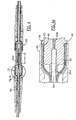
- Figure 1 is an exploded view of a preferred embodiment of the splice of the present invention.
- Figure 2 is a perspective cross sectional view of the splice of Figure 1 .
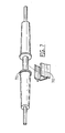
- Figure 3 is an alternative embodiment of the splice of Figure 2 .
- Figure 4 is a cross sectional view of an alternative embodiment of the splice of the present invention with jacketed cables terminated thereto.
- Figure 4a is an enlarged view of a portion of Figure 4 .
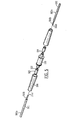
- Figure 5 is an exploded view of the splice of the present invention with the first and second cables.
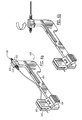
- Figures 6a and 6b are perspective views of the installation device of the present invention.
- Figure 7 is a perspective view showing the splice of the present invention being received in a common clip.
- Figure 8 is a perspective external view of a splice according to the invention.
- the splice 100 of the present invention comprises an elongated housing 110 having first end 101 with a first opening 102, a second end 103 with a second opening 104, and a central cavity 105.
- the housing is essentially seamless between the first and second ends.
- Disposed in the central cavity 105 is a clamping mechanism 106.
- the clamping mechanism 106 defines a platform 121 having fiber-receiving channel 107 open to both the first and second openings 102, 104, a first member 108 adjacent to the fiber-receiving channel, and a second member 120 adjacent the first member 108.
- the first and second members have first and second cam surface 108a, 120a which cooperate such that, when one of either the first or second member is move axially toward the first end 101, the first member 108 moves toward the fiber-receiving channel.
- the clamping mechanism 106 also comprises an actuator 109 to move either the first or second member 108, 120 forward axially.
- the splice 100 also comprises a first buffer crimp 111 disposed at the first end 101, and a second buffer crimp 112 disposed at the second end 103.
- the housing 110 of the splice of the present invention serves preferably several functions. First, it serves to contain the clamping mechanism 106. To this end, the housing 110 is essentially seamless from the first opening to the second opening to protect the clamping mechanism 106 from dirt and debris. As used herein, the term "essentially seamless” means no joints to facilitate relative movement of components of the housing. This essentially seamless construction is possible because the clamping mechanism is actuated axially, requiring access only from the second opening 104.
- the only openings in the housing--i.e., the first and second openings 102, 104, are preferably sealed or covered by boots 401 ( Fig. 4 ) which are slid over the first and second ends 101, 103 after the fiber cables are terminated.
- the housing comprises annular shoulders 130 proximate each end, and against which the boots 401 abut when installed. In addition to providing a stop for the boots, these shoulders also create a seal with the boots (and jacket 403) thereby sealing the first and second openings of the splice from dirt and debris.
- the robust and seamless housing offers significant advantages in terms of durability over prior art splices having housings with seams to provide access to the clamping mechanism or otherwise facilitate movement of the clamping mechanism.
- the housing 110 may also serve to absorb axial loads applied to the cables. Specifically, rather than have the clamping mechanism bear the stress of axial loads applied to the cables, it is preferable to transfer these loads to the housing. Loads may be transferred to the housing in various ways in accordance to the present invention.
- the buffer of each fiber may be secured to its respective buffer crimp, which, in turn, is operatively connected to the housing such that any load applied to the buffer is transferred to the housing.
- buffers 501a, 502b of cables 501, 502, respectively can be crimped to the first and second buffer crimps 111, 112, respectively.
- the first buffer crimp may be operatively connected to the housing in different ways.
- the first buffer crimp 350 may be integral with the housing 110a as shown in Fig. 3 .
- the first buffer crimp may be a discrete component, which is secured to the housing.
- the first buffer crimp 111 may be secured by way of a friction fit (press fit), threaded interengagement, adhesive connection, welded/soldered/braised joint, or any other means for securing one component to another.
- the first buffer crimp is a press fit in the housing.
- the internal threads must be machined in situ. This can leave debris in the housing, which is difficult to remove given the narrowness of the first opening 102.
- the second buffer crimp 112 is also operatively connected to the housing. Unlike the first buffer crimp, however, it cannot be permanently secured to the housing because it preferably moves with the actuator 109, which is slidably disposed within the housing 110 as shown in Fig. 1 . Therefore, to have the load transfer from the second cable, to the second buffer crimp, and then to the housing, it is preferable to have the actuator snuggly held by the housing such that significant force is required to move the actuator either forward, and, more importantly, backward relative to the first end.
- the housing may also absorb load from jacketed cables through the cables' strength members.
- the strength members may be arranged around the outside of the housing and secured thereto by a crimp eyelet.
- the housing preferably comprises texturing at the first and second ends 101, 103 to enhance the retention of the strength members to the housing.
- the texturing is knurling, although any type of texturing including barbs and ridges may be used to increase the friction between the strength members and the housing.
- the housing may be made of any durable material. Suitable materials include, for example, metal such as aluminum, steel, stainless steel, etc., or tough plastics, such as polyetherimide. In a preferred embodiment, the housing comprises aluminum.
- the housing may be integrally molded or it may be formed from different components which are integrated (e.g., welded, glued, press fit) to form a unitary structure having essentially no seams.
- the shape of the housing may vary according to the application.
- the housing is symmetrical such that it may be mounted in a splice holder in any orientation.
- a cylindrical housing 701 is configured to be received in a standard mounting clip 702 in any radial orientation.
- first and second ends, 101, 103 it is preferable to mark the first and second ends, 101, 103, to make them obvious for field installation of the fibers (discussed below).
- one annular ring 801 is marked (in this case molded) on the housing 110b at the first end 101, and two annular rings 802 are marked on the second end 103.
- this embodiment of the housing 110b is designed for non-jacketed cable as opposed to housing 110 ( Fig. 1 ), which has texturing for the strength members and shoulders 130 for the boots.
- the clamping mechanism functions to secure and optically align the first and second fibers.
- the clamping mechanism is known and is disclosed, for example, in U.S. Patent Application No. 20070127873 , which is hereby incorporated by reference.
- the clamping mechanism 106 has a top and bottom and front and back orientation, at least one optical axis, and a pre-actuated state in which the second fiber is not secured to the clamping mechanism and a post-actuated state in which the second fiber is secured to the clamping mechanism.
- the clamping mechanism comprises a platform 121 disposed in the housing 110 and fixed relative thereto both radially and axially.
- the platform defines the fiber-receiving channel 107 along the optical axis to receive the first and second fibers 501b, 502b (see Fig. 5 ).
- the fiber-receiving channel is open to the first and second openings 102, 104.
- the first member 108 is disposed in the housing 110 above and adjacent to the fiber-receiving channel 107.
- the first member has a first cam surface 108a.
- a second member 120 is disposed in the housing and is axially slidable therein.
- the second member has a second cam surface 120a adjacent the first cam surface 108a and is configured such that, upon forward motion of the second member, the first member is urged downward (or into the platform 121) as a result of a camming action between the first and second cam surfaces 108a, 120a.
- first member 108 remains stationary relative to the platform 121 and the second member moves forward
- the slope of the first and second cam surfaces 108a and 120a could be reversed, in which case, the second member 120 would remain stationary relative to the housing, while the first member would move forward during actuation.
- the second member may be integral to the housing 110 since it is not moving.
- the actuator 109 is disposed slidably within the housing 110 behind and adjacent to the second member and configured, such that, when moved forward, it forces the second member forward relative to the first member.
- the actuator could be configured to push the first member forward relative to the housing.
- a buffer stop 150 functions to position the fiber axially.
- the same buffer stop is used to position buffered fibers of varying diameter-e.g. 250 to 900 ⁇ m.
- the buffer stop comprises a lead-in portion 150a, which tapers into a narrow portion 150b that is aligned with the fiber-receiving channel 107.
- the lead-in portion serves to guide the bare fiber 501b into the narrow portion 150b, and the narrow portion, in turn, serves to guide the bare fiber 501b into the fiber-receiving channel 107.
- the degree of taper of the lead-in portion 150a is optimized such that it can accommodate cables of varying diameter. It should be understood that if the lead-in portion 150a is tapered, the buffer 501a on a 900 ⁇ m cable, for example, will abut the buffer stop 150 at an earlier point than that of a 250 ⁇ m cable. In other words, the buffer 501a of a 900 ⁇ m cable cannot be inserted into the buffer stop 150 as far as that of a 250 ⁇ m cable.
- the differential may be addressed in different ways to enable the same splice to be used for cables of different diameters.
- the taper might be very steep-i.e., approaching normal to the optical axis such that buffers of the 250 and 900 ⁇ m cables abut the buffer stop at approximately the same axial point, thereby minimizing the differential.
- this approach compromises the lead-in function of the buffer stop, as the bare fiber is more likely to stub against the buffer stop rather being lead into the narrow portion. This can cause damage to the bare fiber.
- the 250 and 900 ⁇ m cables may be stripped such that the bare fiber extends further for the 900 ⁇ m cable to compensate for the earlier abutment of the 900 ⁇ m buffer against the buffer stop.
- This approach has the drawback of requiring different installation procedures depending on the diameter of the cable, which is contrary to the objective of standardizing the splice process.
- a preferred approach utilizes an optimized taper which is relatively steep to minimize the differential, but not too steep as to compromise its lead-in functionality. Although this will result in an appreciable differential, the clamping mechanism of the present invention is able to accommodate it. That is, the clamping mechanism of the present invention has a relatively long length of engagement in the fiber-receiving channel. This is due to a relatively elongated, planar surface of the first member bearing down on the fiber in the fiber-receiving channel. For example, in commercial embodiments, the length of engagement is about 4mm. This relatively long length provides the tolerance necessary to accommodate the differential resulting from a common splice being used for cables of different diameter.
- the buffer stop 150 is integral with the housing 110 as shown in Fig. 2 .
- the buffer stop 350 can be a discrete component as shown in Fig. 3 .
- buffer stop 350 is inserted through the second opening and is pushed forward until it abuts a shoulder 351 on the inside of the housing 110a.
- the cables Before terminating the fibers, the cables must be stripped and cleaved such that the bare fiber 501b, 502b extends beyond the buffer 501a, 502a of cables 501, 502, respectively.
- This step may be performed using existing stripping and cleaving tools available commercially from multiple manufacturing sources, such as Clauss and Furukawa Electric Company.
- the bare fiber extends beyond the buffer by about 8 mm.
- the first buffer crimp 111 is crimped around the buffer to secure the first cable to the housing.
- the second bare fiber 502b is inserted into the second opening 104 such that the second fiber 502b is received in the fiber-receiving channel 107 until the end 502c of the second fiber 502b contacts the end 501c of the first fiber 501b.
- optical gel may be added prior to the insertion of the second fiber to enhance the optical coupling of the first and second fibers.
- the actuator 109 Fig. 1
- the actuator 109 is moved toward the first end to urge the first member into the first and second fibers and secure them in the fiber-receiving channel.
- the second buffer crimp 112 is crimped around the buffer of the second cable 502 to secure it to the housing.
- the process further comprises laying the strength members 404 over the ends 101, 103 of the housing and crimping them in place, along with the jacket 403, with a crimp eyelet 402.
- a boot 401 is slid over the housing end, further securing the strength members to the housing and sealing the sealing the openings of the housing from dirt and debris.
- Fig. 4 shows an alternative embodiment in which the first buffer crimp and the buffer stop are both integral with the housing 110c.
- the above process is simplified by virtue of a compact tool that can be used for terminating fibers in the splice of the present invention.
- the installation device 600 is shown.
- the device comprises a base 601 from which extend a cable clamp 602 and a swivel splice clamp 603.
- the cable clamp 602 comprises a hinged mechanism having jaws 605, which are resiliently biased closed, and a lever 604 to open the jaws.
- the swivel splice clamp also has jaws 606 which are biased closed and firmly grip the splice housing 110 when inserted therein.
- the splice 100 is inserted into the jaws 606 and a stripped first cable is inserted into the jaws 605. While squeezing the lever 604 the first cable is inserted into the first opening of the splice and is pushed forward to form a bend in the fiber. At this point, the lever is released, causing the fiber to be held relative to the splice. The bend provides an urging force to urge the push the cable into the splice to ensure that the buffer of the cable abuts the buffer stop as described above. The first buffer crimp is then crimped to secure the first cable to the splice housing 110.
- the first cable is removed from the cable holder and the swivel splice clamp is rotated 180 degrees to present the second opening to the cable clamp.
- the same procedure is performed with the second cable.
- the clamping mechanism is actuated to secure the first and second fibers in the fiber-receiving channel as described above. This actuation can be performed using standard tooling such as the Pro-crimper available through Tyco Electronics (Harrisburg, PA).
- the ruggedness of the splice housing and the axial actuation provides for a host of benefits including durability, standardization, and field installability using a compact and versatile tool. Still other benefits and application will be obvious to one of skill in the art in light of this disclosure.
Abstract
Description
- The present invention relates to a field-installable splice for optical fiber cables of varying diameter.
- Optical fiber cables (herein "cables") are ubiquitous in data and telecommunications. A typical cable comprises an optical fiber encased by a buffer, which protects the fiber and provides strength to the cable. The diameter of a buffered fiber typically ranges from 250 to 900 µm depending upon the application. Cables are also frequently jacketed in which aramide strength members surround the buffer and are encased in a protective polymeric sheathing. These cables, both jacketed and non- jacketed, form the backbone of essentially all optical communications.
- Frequently, cables must be connected together to effect an optical coupling between them. This connection is performed using a splice. Although splices are common and well known in the art, the applicant has identified a number of properties that splices should possess, but few do.
- First, a splice must hold the cables such that the fibers are in optical alignment. This requires aligning the core of one fiber with the core of the other. Considering that cores for multimode fibers are only 50 to 62.5 µm, and those for single mode fibers are even smaller at 8 to 10 µm, tolerances for radial offset can be as low as 1 µm. Thus, extremely accurate and precise positioning of the fibers is necessary to achieve suitable optical coupling.
- Second, since different cables must be connected in networks in the field, a splice should be field installable, meaning a technician should be able to use relatively simple tools to optically couple the fibers in a simple and reliable way.
- Third, the splice must be durable and resilient to common environmental assaults such as dirt and debris. If dirt or other debris is able to penetrate the housing, it can wreak havoc with the mechanism that effects the splice or even degrade the optical performance of the splice.
- Fourth, the splice should be structurally robust and resist pulling forces on the cables it joins. To this end, the applicant has recognized that transferring the axial forces on the cable to a load bearing component of the splice and away from the clamping mechanism of the splice provides for the most robust design. Transferring these forces to a load bearing component is particularly important with respect to jacketed fibers. That is, the splice should be capable of accommodating jacketed fibers and exploiting the strength members that they contain by securing these strength members to the load bearing component of the splice.
- Fifth, a splice should exploit certain standards and commonality among other optical components to make it universal. For example, since a splice should be field installable, it would be preferable that the splice uses fiber termination mechanisms that are already in use in field-installable connectors. In addition to using similar mechanisms and tools as used in the connector field, the splice should also interengage within closures with known and commercially available holders such as those manufactured by Richco.
- Sixth, the splice should be capable of coupling fibers independent of the buffer or coating diameter. That is, the splice should be capable of splicing fibers having buffer diameters ranging from 250 to 900µm, which are common in the industry.
- Although the prior art offers splices which provide some of these features, none provide all. For example, one common approach is a fused splice in which the optical fibers are fused together using an energy source such as a laser, electric arc, or gas flames to heat the fiber ends. Although such a design is advantageous from the standpoint of optical alignment and usually results in an optical coupling having a low insertion loss, it requires specialized equipment and does not exploit techniques and tools already in use for terminating connectors, thereby diminishing its versatility.
- Another prior art approach to splicing is the use of a clam-shell type splice as used, for example, in the CoreLink product line (offered by Tyco Electronics, Harrisburg, PA). In this design, two halves of a splice are urged together by resilient means such as a spring member. To effect the splice, a tool is inserted into the splice to wedge or cam the two halves apart to allow the fibers to be inserted. When the fibers are in place, the camming or wedging tool in removed and the splice halves clamp shut by virtue of the resilient means. Although this splice design has been effective in the past and provides for adequate optical alignment and simple field installation, it is not particularly durable. That is, there is a seam along its length, which is susceptible to dirt and other debris. Furthermore, axial loads on the cable are transmitted directly through the optical splice, rather than being transferred to a separate load-carrying component. Furthermore, the splice tends to be an unusual shape (typically an elongated rectilinear shape), and consequently does not interengage with standard holders. Finally, the clamping mechanism it uses is unique and not used in field installable connectors, thus, the tooling required for this splice is unique to this splice.
- Yet another splice involves rotational actuation and is offered by Coming. Specifically, this splice involves one component rotating relative to another to cam down on a fiber joint and hold the fibers together. Although this device is advantageous from the standpoint of its field installability, the fiber alignment may suffer. Specifically, since the rotational actuation involves asymmetric radial pressure on the fibers within, a certain degree of fiber dislocation may occur during actuation. Furthermore, this design is not particularly durable. Specifically, to accommodate the rotational actuation, the housing is split and has annular seam. Such a seam is susceptible to dirt and other debris. Furthermore, this design is susceptible to axial loads translated through the optical fibers since the loads are not transferred to a load bearing component in the splice.
- There is a need for a splice that provides good fiber alignment, field installability, durability, and versatility with respect to using commercially available tools and splice accessories.
- This problem is solved by a splice according to claim 1.
- The invention is a splice for connecting two segments of optical fiber cable. The splice comprises an elongated housing having a first end with a first opening, a second end with a second opening, and a central cavity extending between the first end and the second end. A clamping mechanism is disposed in the central cavity. The clamping mechanism comprises a platform defining a fiber-receiving channel open to both of the first and second openings, a first member adjacent to the fiber-receiving channel and having a first cam surface, and a second member having a second cam surface. The first and second cam surfaces cooperate such that relative movement of the first and second members toward the first end causes the first member to move toward the fiber-receiving channel. An actuator is arranged to cause relative movement of the first and second members toward the first end. A first buffer crimp is disposed at the first opening, and a second buffer crimp is disposed at the second opening.
- The invention will now be described by way of example with reference to the accompanying drawings wherein:
-
Figure 1 is an exploded view of a preferred embodiment of the splice of the present invention. -
Figure 2 is a perspective cross sectional view of the splice ofFigure 1 . -
Figure 3 is an alternative embodiment of the splice ofFigure 2 . -
Figure 4 is a cross sectional view of an alternative embodiment of the splice of the present invention with jacketed cables terminated thereto. -
Figure 4a is an enlarged view of a portion ofFigure 4 . -
Figure 5 is an exploded view of the splice of the present invention with the first and second cables. -
Figures 6a and 6b are perspective views of the installation device of the present invention. -
Figure 7 is a perspective view showing the splice of the present invention being received in a common clip. -
Figure 8 is a perspective external view of a splice according to the invention. - Referring to
Fig. 1 , an embodiment of thesplice 100 of the present invention is shown. The splice comprises anelongated housing 110 havingfirst end 101 with afirst opening 102, asecond end 103 with asecond opening 104, and acentral cavity 105. The housing is essentially seamless between the first and second ends. Disposed in thecentral cavity 105 is aclamping mechanism 106. Theclamping mechanism 106 defines aplatform 121 having fiber-receivingchannel 107 open to both the first andsecond openings first member 108 adjacent to the fiber-receiving channel, and asecond member 120 adjacent thefirst member 108. The first and second members have first andsecond cam surface first end 101, thefirst member 108 moves toward the fiber-receiving channel. Theclamping mechanism 106 also comprises anactuator 109 to move either the first orsecond member splice 100 also comprises afirst buffer crimp 111 disposed at thefirst end 101, and asecond buffer crimp 112 disposed at thesecond end 103. These elements are described in greater detail below. - The
housing 110 of the splice of the present invention serves preferably several functions. First, it serves to contain theclamping mechanism 106. To this end, thehousing 110 is essentially seamless from the first opening to the second opening to protect theclamping mechanism 106 from dirt and debris. As used herein, the term "essentially seamless" means no joints to facilitate relative movement of components of the housing. This essentially seamless construction is possible because the clamping mechanism is actuated axially, requiring access only from thesecond opening 104. - Furthermore, the only openings in the housing--i.e., the first and
second openings Fig. 4 ) which are slid over the first and second ends 101, 103 after the fiber cables are terminated. In one embodiment, the housing comprisesannular shoulders 130 proximate each end, and against which theboots 401 abut when installed. In addition to providing a stop for the boots, these shoulders also create a seal with the boots (and jacket 403) thereby sealing the first and second openings of the splice from dirt and debris. The robust and seamless housing offers significant advantages in terms of durability over prior art splices having housings with seams to provide access to the clamping mechanism or otherwise facilitate movement of the clamping mechanism. - Because the
housing 110 is particularly robust in the present invention, it may also serve to absorb axial loads applied to the cables. Specifically, rather than have the clamping mechanism bear the stress of axial loads applied to the cables, it is preferable to transfer these loads to the housing. Loads may be transferred to the housing in various ways in accordance to the present invention. For example, the buffer of each fiber may be secured to its respective buffer crimp, which, in turn, is operatively connected to the housing such that any load applied to the buffer is transferred to the housing. Specifically,buffers cables - Although crimping a buffer to a buffer crimp is known in the art, the applicant has found that the use of a hexagonal crimp die provides suitable plastic compressive deformation of the eyelet, while still effectively captivating the buffer. Furthermore, the applicant has found that internally threading the buffer crimps 111, 112 enhances the retention to the cable buffer.
- The first buffer crimp may be operatively connected to the housing in different ways. For example, the
first buffer crimp 350 may be integral with thehousing 110a as shown inFig. 3 . Alternatively, the first buffer crimp may be a discrete component, which is secured to the housing. In this regard, thefirst buffer crimp 111 may be secured by way of a friction fit (press fit), threaded interengagement, adhesive connection, welded/soldered/braised joint, or any other means for securing one component to another. Preferably, the first buffer crimp is a press fit in the housing. By having thefirst buffer crimp 111 discrete from the housing, the threads may be machined into the buffer crimp apart from the housing to avoid leaving debris in the housing. By way of contrast, if thefirst buffer crimp 311 is integral to thehousing 110a, as shown in the alternative embodiment ofFig. 3 , the internal threads must be machined in situ. This can leave debris in the housing, which is difficult to remove given the narrowness of thefirst opening 102. - The
second buffer crimp 112 is also operatively connected to the housing. Unlike the first buffer crimp, however, it cannot be permanently secured to the housing because it preferably moves with theactuator 109, which is slidably disposed within thehousing 110 as shown inFig. 1 . Therefore, to have the load transfer from the second cable, to the second buffer crimp, and then to the housing, it is preferable to have the actuator snuggly held by the housing such that significant force is required to move the actuator either forward, and, more importantly, backward relative to the first end. - The housing may also absorb load from jacketed cables through the cables' strength members. Specifically, the strength members may be arranged around the outside of the housing and secured thereto by a crimp eyelet. Referring to
Fig. 1 , the housing preferably comprises texturing at the first and second ends 101, 103 to enhance the retention of the strength members to the housing. In this embodiment, the texturing is knurling, although any type of texturing including barbs and ridges may be used to increase the friction between the strength members and the housing. - The housing may be made of any durable material. Suitable materials include, for example, metal such as aluminum, steel, stainless steel, etc., or tough plastics, such as polyetherimide. In a preferred embodiment, the housing comprises aluminum. The housing may be integrally molded or it may be formed from different components which are integrated (e.g., welded, glued, press fit) to form a unitary structure having essentially no seams.
- The shape of the housing may vary according to the application. Preferably, the housing is symmetrical such that it may be mounted in a splice holder in any orientation. For example, referring to
Fig. 7 , acylindrical housing 701 is configured to be received in astandard mounting clip 702 in any radial orientation. - Given the symmetry of the preferred embodiment of the housing, it is preferable to mark the first and second ends, 101, 103, to make them obvious for field installation of the fibers (discussed below). For example, referring to
Fig 8 , oneannular ring 801 is marked (in this case molded) on thehousing 110b at thefirst end 101, and twoannular rings 802 are marked on thesecond end 103. It is also worthwhile to mention that this embodiment of thehousing 110b is designed for non-jacketed cable as opposed to housing 110 (Fig. 1 ), which has texturing for the strength members andshoulders 130 for the boots. - Referring back to
Figure 1 , the clamping mechanism functions to secure and optically align the first and second fibers. The clamping mechanism is known and is disclosed, for example, inU.S. Patent Application No. 20070127873 , which is hereby incorporated by reference. - Generally, the
clamping mechanism 106 has a top and bottom and front and back orientation, at least one optical axis, and a pre-actuated state in which the second fiber is not secured to the clamping mechanism and a post-actuated state in which the second fiber is secured to the clamping mechanism. The clamping mechanism comprises aplatform 121 disposed in thehousing 110 and fixed relative thereto both radially and axially. The platform defines the fiber-receivingchannel 107 along the optical axis to receive the first andsecond fibers Fig. 5 ). The fiber-receiving channel is open to the first andsecond openings first member 108 is disposed in thehousing 110 above and adjacent to the fiber-receivingchannel 107. The first member has afirst cam surface 108a. Asecond member 120 is disposed in the housing and is axially slidable therein. The second member has asecond cam surface 120a adjacent thefirst cam surface 108a and is configured such that, upon forward motion of the second member, the first member is urged downward (or into the platform 121) as a result of a camming action between the first andsecond cam surfaces - Although in the embodiment shown in
Fig. 1 thefirst member 108 remains stationary relative to theplatform 121 and the second member moves forward, other embodiments are possible. For example, the slope of the first andsecond cam surfaces second member 120 would remain stationary relative to the housing, while the first member would move forward during actuation. In such an embodiment, the second member may be integral to thehousing 110 since it is not moving. - The
actuator 109 is disposed slidably within thehousing 110 behind and adjacent to the second member and configured, such that, when moved forward, it forces the second member forward relative to the first member. Alternatively, the actuator could be configured to push the first member forward relative to the housing. - Referring to
Fig. 2 , abuffer stop 150 functions to position the fiber axially. In a preferred embodiment, the same buffer stop is used to position buffered fibers of varying diameter-e.g. 250 to 900µm. The buffer stop comprises a lead-inportion 150a, which tapers into anarrow portion 150b that is aligned with the fiber-receivingchannel 107. The lead-in portion serves to guide thebare fiber 501b into thenarrow portion 150b, and the narrow portion, in turn, serves to guide thebare fiber 501b into the fiber-receivingchannel 107. - The degree of taper of the lead-in
portion 150a is optimized such that it can accommodate cables of varying diameter. It should be understood that if the lead-inportion 150a is tapered, thebuffer 501a on a 900 µm cable, for example, will abut the buffer stop 150 at an earlier point than that of a 250µm cable. In other words, thebuffer 501a of a 900µm cable cannot be inserted into the buffer stop 150 as far as that of a 250µm cable. Consequently, if both the 900µm and 250µm cables are stripped such that an equal length ofbare fiber 501b extends from thebuffer 501a, then the fiber of the 900µm cable would not extend into the fiber-receiving channel as far as the that of the 250µm cable. This difference in the extension of the bare fiber into the fiber-receiving channel for cables of different diameters is referred to herein as "differential." - The differential may be addressed in different ways to enable the same splice to be used for cables of different diameters. First, the taper might be very steep-i.e., approaching normal to the optical axis such that buffers of the 250 and 900 µm cables abut the buffer stop at approximately the same axial point, thereby minimizing the differential. However, this approach compromises the lead-in function of the buffer stop, as the bare fiber is more likely to stub against the buffer stop rather being lead into the narrow portion. This can cause damage to the bare fiber. Alternatively, the 250 and 900 µm cables may be stripped such that the bare fiber extends further for the 900 µm cable to compensate for the earlier abutment of the 900 µm buffer against the buffer stop. This approach, however, has the drawback of requiring different installation procedures depending on the diameter of the cable, which is contrary to the objective of standardizing the splice process.
- A preferred approach utilizes an optimized taper which is relatively steep to minimize the differential, but not too steep as to compromise its lead-in functionality. Although this will result in an appreciable differential, the clamping mechanism of the present invention is able to accommodate it. That is, the clamping mechanism of the present invention has a relatively long length of engagement in the fiber-receiving channel. This is due to a relatively elongated, planar surface of the first member bearing down on the fiber in the fiber-receiving channel. For example, in commercial embodiments, the length of engagement is about 4mm. This relatively long length provides the tolerance necessary to accommodate the differential resulting from a common splice being used for cables of different diameter.
- Preferably, the
buffer stop 150 is integral with thehousing 110 as shown inFig. 2 . Alternatively, the buffer stop 350 can be a discrete component as shown inFig. 3 . In this embodiment,buffer stop 350 is inserted through the second opening and is pushed forward until it abuts ashoulder 351 on the inside of thehousing 110a. - Referring to
Fig. 5 , the process of terminating fibers in the splice will be described. Before terminating the fibers, the cables must be stripped and cleaved such that thebare fiber buffer cables first fiber 501b is inserted into thefirst opening 102 such that thefirst fiber 501b is received in the fiber-receivingchannel 107 and until thebuffer 501a abuts thebuffer stop 150. At this point, thefirst buffer crimp 111 is crimped around the buffer to secure the first cable to the housing. Next, the secondbare fiber 502b is inserted into thesecond opening 104 such that thesecond fiber 502b is received in the fiber-receivingchannel 107 until theend 502c of thesecond fiber 502b contacts theend 501c of thefirst fiber 501b. Optionally, optical gel may be added prior to the insertion of the second fiber to enhance the optical coupling of the first and second fibers. With the second bare fiber optically coupled to the first bare fiber, the actuator 109 (Fig. 1 ) is moved toward the first end to urge the first member into the first and second fibers and secure them in the fiber-receiving channel. Finally, thesecond buffer crimp 112 is crimped around the buffer of thesecond cable 502 to secure it to the housing. - Referring to
Fig. 4 , if the fiber cable is jacketed and hasstrength members 404, the process further comprises laying thestrength members 404 over theends jacket 403, with acrimp eyelet 402. Next, aboot 401 is slid over the housing end, further securing the strength members to the housing and sealing the sealing the openings of the housing from dirt and debris. (Note thatFig. 4 shows an alternative embodiment in which the first buffer crimp and the buffer stop are both integral with thehousing 110c.) - The above process is simplified by virtue of a compact tool that can be used for terminating fibers in the splice of the present invention. Referring to
Figs. 6a and 6b , theinstallation device 600 is shown. The device comprises a base 601 from which extend acable clamp 602 and aswivel splice clamp 603. Thecable clamp 602 comprises a hingedmechanism having jaws 605, which are resiliently biased closed, and alever 604 to open the jaws. The swivel splice clamp also hasjaws 606 which are biased closed and firmly grip thesplice housing 110 when inserted therein. - In operation, the
splice 100 is inserted into thejaws 606 and a stripped first cable is inserted into thejaws 605. While squeezing thelever 604 the first cable is inserted into the first opening of the splice and is pushed forward to form a bend in the fiber. At this point, the lever is released, causing the fiber to be held relative to the splice. The bend provides an urging force to urge the push the cable into the splice to ensure that the buffer of the cable abuts the buffer stop as described above. The first buffer crimp is then crimped to secure the first cable to thesplice housing 110. - Once the first cable is connected to the splice, the first cable is removed from the cable holder and the swivel splice clamp is rotated 180 degrees to present the second opening to the cable clamp. The same procedure is performed with the second cable. Before the second buffer crimp is crimped, however, the clamping mechanism is actuated to secure the first and second fibers in the fiber-receiving channel as described above. This actuation can be performed using standard tooling such as the Pro-crimper available through Tyco Electronics (Harrisburg, PA).
- Therefore, the ruggedness of the splice housing and the axial actuation provides for a host of benefits including durability, standardization, and field installability using a compact and versatile tool. Still other benefits and application will be obvious to one of skill in the art in light of this disclosure.
Claims (6)
- A splice (100) for connecting two segments of optical fiber cable (501, 502),
characterized in that:the splice comprises an elongated housing (110) having a first end (101) with a first opening (102), a second end (103) with a second opening (104), and a central cavity (105) extending between the first end (101) and the second end (103);a clamping mechanism (106) is disposed in the central cavity (105), the clamping mechanism comprises a platform (121) defining a fiber-receiving channel (107) open to both of the first and second openings (102, 104), a first member (108) adjacent to the fiber-receiving channel (107) and having a first cam surface (108a), and a second member (120) having a second cam surface (120a), the first and second cam surfaces cooperating such that relative movement of the first and second members (108, 120) toward the first end (101) causes the first member (108) to move toward the fiber-receiving channel (107), and an actuator (109) arranged to cause relative movement of the first and second members (108, 120) toward the first end;a first buffer crimp (111) disposed at the first opening (102); anda second buffer crimp (112) disposed at the second opening (104). - The splice of claim 1, wherein a buffer stop (150) is disposed in the housing (110) between the first opening (102) and the clamping mechanism (106), the buffer stop (150) defines a lead-in portion (150a) tapering down to a narrow portion (150b) aligned with the fiber-receiving channel (107).
- The splice of claim 2, wherein the buffer stop (150) is integral with the housing (110).
- The splice of claim 2, wherein the buffer stop (350) is a discrete insert and the housing (110a) defines an inner shoulder (351) at the first end (101) against which the buffer stop (350) abuts.
- The splice of any preceding claim, wherein the first buffer crimp (111) comprises internal threads.
- The splice of claim 1, wherein the second buffer crimp (112) is integral with the actuator (109) and defines a passage aligned with the fiber-receiving channel (107).
Applications Claiming Priority (1)
| Application Number | Priority Date | Filing Date | Title |
|---|---|---|---|
| US11/949,435 US7461983B1 (en) | 2007-12-03 | 2007-12-03 | Field-installable optical splice |
Publications (1)
| Publication Number | Publication Date |
|---|---|
| EP2068183A1 true EP2068183A1 (en) | 2009-06-10 |
Family
ID=40090528
Family Applications (1)
| Application Number | Title | Priority Date | Filing Date |
|---|---|---|---|
| EP08170495A Withdrawn EP2068183A1 (en) | 2007-12-03 | 2008-12-02 | Field-installable optical splice |
Country Status (4)
| Country | Link |
|---|---|
| US (1) | US7461983B1 (en) |
| EP (1) | EP2068183A1 (en) |
| JP (1) | JP5164813B2 (en) |
| CN (1) | CN101477232B (en) |
Families Citing this family (11)
| Publication number | Priority date | Publication date | Assignee | Title |
|---|---|---|---|---|
| US20090034916A1 (en) * | 2007-07-10 | 2009-02-05 | Leblanc Thomas G | Fiber optic cable with in-line fiber optic splice |
| US8333519B2 (en) * | 2008-08-29 | 2012-12-18 | Adc Telecommunications, Inc. | Splice of fiber optic cables |
| US7925135B2 (en) * | 2008-09-03 | 2011-04-12 | Tyco Electronics Corporation | Cable clamping devices and methods for using the same |
| EP2330707A1 (en) * | 2009-12-03 | 2011-06-08 | Tyco Electronics Raychem BVBA | Gel sealing device |
| MX2011007766A (en) * | 2009-12-04 | 2011-08-12 | Afl Telecommunications Llc | Quad optical time domain reflectometer (otdr). |
| US8915659B2 (en) * | 2010-05-14 | 2014-12-23 | Adc Telecommunications, Inc. | Splice enclosure arrangement for fiber optic cables |
| US8885998B2 (en) | 2010-12-09 | 2014-11-11 | Adc Telecommunications, Inc. | Splice enclosure arrangement for fiber optic cables |
| US20120255664A1 (en) | 2011-04-08 | 2012-10-11 | Richard Lindner | Method and apparatus for determining proper curing of pipe liners using distributed temperature sensing |
| US20110186203A1 (en) | 2011-04-08 | 2011-08-04 | Richard Lindner | Method and apparatus for determining proper curing of pipe liners using distributed temperature sensing |
| WO2013104125A1 (en) * | 2012-01-12 | 2013-07-18 | 3M Innovative Properties Company | Field mountable duplex optical fiber connector with mechanical splice elements |
| US20140161401A1 (en) | 2012-12-11 | 2014-06-12 | Tyco Electronics Corporation | Field-installable optical slice |
Citations (3)
| Publication number | Priority date | Publication date | Assignee | Title |
|---|---|---|---|---|
| DE3704789A1 (en) * | 1986-12-02 | 1988-08-25 | Rainer Wadewitz | Optical plug-in connector for optical waveguides |
| EP0421305A1 (en) * | 1989-10-02 | 1991-04-10 | Gte Control Devices Of Puerto Rico Incorporated | Fiber optic splice assembly |
| US20070127873A1 (en) * | 2004-06-30 | 2007-06-07 | Tyco Electronics Corporation | Optical fiber clamping assembly |
Family Cites Families (10)
| Publication number | Priority date | Publication date | Assignee | Title |
|---|---|---|---|---|
| US5085494A (en) | 1990-10-29 | 1992-02-04 | Aurora Optics, Inc. | Fiber optic splice means and method |
| US5201019A (en) | 1991-07-15 | 1993-04-06 | Amphenol Corporation | Fiber optic splice connection and a method of making same |
| US5469522A (en) | 1993-12-02 | 1995-11-21 | Litecom, Inc. | Optical fiber splice interconnection and usage method |
| JP3241596B2 (en) * | 1996-06-05 | 2001-12-25 | ヒロセ電機株式会社 | Optical fiber cable connector and connection method |
| JPH10197741A (en) * | 1997-01-06 | 1998-07-31 | Tatsuta Electric Wire & Cable Co Ltd | Optical fiber connector |
| JP2000121863A (en) * | 1998-10-20 | 2000-04-28 | Sumitomo Electric Ind Ltd | Mechanical splice, coated optical fiber connection part, and coated optical fiber with optical connector |
| US6439780B1 (en) * | 2000-08-31 | 2002-08-27 | Corning Cable Systems Llc | Field-installable fiber optic ribbon connector and installation tool |
| KR100442620B1 (en) * | 2002-05-03 | 2004-08-02 | 삼성전자주식회사 | Distribution optical cable |
| EP1644764B1 (en) * | 2003-06-30 | 2020-03-04 | CommScope Technologies LLC | Optical fiber clamping assembly |
| US20050191014A1 (en) | 2004-03-01 | 2005-09-01 | Renfro James G.Jr. | Fiber optic splice component |
-
2007
- 2007-12-03 US US11/949,435 patent/US7461983B1/en active Active
-
2008
- 2008-12-01 JP JP2008305804A patent/JP5164813B2/en not_active Expired - Fee Related
- 2008-12-02 EP EP08170495A patent/EP2068183A1/en not_active Withdrawn
- 2008-12-03 CN CN2008102463835A patent/CN101477232B/en not_active Expired - Fee Related
Patent Citations (3)
| Publication number | Priority date | Publication date | Assignee | Title |
|---|---|---|---|---|
| DE3704789A1 (en) * | 1986-12-02 | 1988-08-25 | Rainer Wadewitz | Optical plug-in connector for optical waveguides |
| EP0421305A1 (en) * | 1989-10-02 | 1991-04-10 | Gte Control Devices Of Puerto Rico Incorporated | Fiber optic splice assembly |
| US20070127873A1 (en) * | 2004-06-30 | 2007-06-07 | Tyco Electronics Corporation | Optical fiber clamping assembly |
Also Published As
| Publication number | Publication date |
|---|---|
| US7461983B1 (en) | 2008-12-09 |
| JP5164813B2 (en) | 2013-03-21 |
| CN101477232B (en) | 2012-06-27 |
| JP2009139948A (en) | 2009-06-25 |
| CN101477232A (en) | 2009-07-08 |
Similar Documents
| Publication | Publication Date | Title |
|---|---|---|
| US7461983B1 (en) | Field-installable optical splice | |
| US11550105B2 (en) | Fiber plug connector with seal and threaded region | |
| EP2724188B1 (en) | Field terminable optical connector with splice element for jacketed cable | |
| US8118494B2 (en) | Remote grip optical fiber connector | |
| US7811006B2 (en) | Field installable fiber optic connector and installation tool | |
| WO2013104125A1 (en) | Field mountable duplex optical fiber connector with mechanical splice elements | |
| MXPA06010746A (en) | Field installable optical fiber connector. | |
| US10324262B1 (en) | Field terminable fiber optic connectors | |
| US8075198B2 (en) | Reversible fiber connector with mechanical sliding splice | |
| JP3530434B2 (en) | Optical ferrule and method of installing fiber without adhesive | |
| US20090310918A1 (en) | Reversible fiber connector with mechanical splice and sliding lock | |
| EP2914994B1 (en) | Terminus assembly for terminating an optical cable | |
| JP3404340B2 (en) | Quick connection fiber optic connector | |
| US20210271029A1 (en) | Sealed optical cable assemblies and methods of fabricating the same | |
| US9022667B2 (en) | Pin and socket terminus assemblies for terminating optical cables | |
| US9256031B2 (en) | Terminus assembly for terminating an optical cable | |
| WO2004008212A1 (en) | Optical fibre connector assembly tool |
Legal Events
| Date | Code | Title | Description |
|---|---|---|---|
| PUAI | Public reference made under article 153(3) epc to a published international application that has entered the european phase |
Free format text: ORIGINAL CODE: 0009012 |
|
| AK | Designated contracting states |
Kind code of ref document: A1 Designated state(s): AT BE BG CH CY CZ DE DK EE ES FI FR GB GR HR HU IE IS IT LI LT LU LV MC MT NL NO PL PT RO SE SI SK TR |
|
| AX | Request for extension of the european patent |
Extension state: AL BA MK RS |
|
| 17P | Request for examination filed |
Effective date: 20091111 |
|
| 17Q | First examination report despatched |
Effective date: 20091207 |
|
| AKX | Designation fees paid |
Designated state(s): DE FR GB |
|
| STAA | Information on the status of an ep patent application or granted ep patent |
Free format text: STATUS: THE APPLICATION IS DEEMED TO BE WITHDRAWN |
|
| 18D | Application deemed to be withdrawn |
Effective date: 20100618 |