EP2067983A1 - Valve assembly for an injection valve and injection valve - Google Patents
Valve assembly for an injection valve and injection valve Download PDFInfo
- Publication number
- EP2067983A1 EP2067983A1 EP07023476A EP07023476A EP2067983A1 EP 2067983 A1 EP2067983 A1 EP 2067983A1 EP 07023476 A EP07023476 A EP 07023476A EP 07023476 A EP07023476 A EP 07023476A EP 2067983 A1 EP2067983 A1 EP 2067983A1
- Authority
- EP
- European Patent Office
- Prior art keywords
- valve
- needle
- surface layer
- valve needle
- valve body
- Prior art date
- Legal status (The legal status is an assumption and is not a legal conclusion. Google has not performed a legal analysis and makes no representation as to the accuracy of the status listed.)
- Granted
Links
Images


Classifications
-
- F—MECHANICAL ENGINEERING; LIGHTING; HEATING; WEAPONS; BLASTING
- F02—COMBUSTION ENGINES; HOT-GAS OR COMBUSTION-PRODUCT ENGINE PLANTS
- F02M—SUPPLYING COMBUSTION ENGINES IN GENERAL WITH COMBUSTIBLE MIXTURES OR CONSTITUENTS THEREOF
- F02M61/00—Fuel-injectors not provided for in groups F02M39/00 - F02M57/00 or F02M67/00
- F02M61/16—Details not provided for in, or of interest apart from, the apparatus of groups F02M61/02 - F02M61/14
- F02M61/166—Selection of particular materials
-
- C—CHEMISTRY; METALLURGY
- C23—COATING METALLIC MATERIAL; COATING MATERIAL WITH METALLIC MATERIAL; CHEMICAL SURFACE TREATMENT; DIFFUSION TREATMENT OF METALLIC MATERIAL; COATING BY VACUUM EVAPORATION, BY SPUTTERING, BY ION IMPLANTATION OR BY CHEMICAL VAPOUR DEPOSITION, IN GENERAL; INHIBITING CORROSION OF METALLIC MATERIAL OR INCRUSTATION IN GENERAL
- C23C—COATING METALLIC MATERIAL; COATING MATERIAL WITH METALLIC MATERIAL; SURFACE TREATMENT OF METALLIC MATERIAL BY DIFFUSION INTO THE SURFACE, BY CHEMICAL CONVERSION OR SUBSTITUTION; COATING BY VACUUM EVAPORATION, BY SPUTTERING, BY ION IMPLANTATION OR BY CHEMICAL VAPOUR DEPOSITION, IN GENERAL
- C23C28/00—Coating for obtaining at least two superposed coatings either by methods not provided for in a single one of groups C23C2/00 - C23C26/00 or by combinations of methods provided for in subclasses C23C and C25C or C25D
- C23C28/04—Coating for obtaining at least two superposed coatings either by methods not provided for in a single one of groups C23C2/00 - C23C26/00 or by combinations of methods provided for in subclasses C23C and C25C or C25D only coatings of inorganic non-metallic material
- C23C28/044—Coating for obtaining at least two superposed coatings either by methods not provided for in a single one of groups C23C2/00 - C23C26/00 or by combinations of methods provided for in subclasses C23C and C25C or C25D only coatings of inorganic non-metallic material coatings specially adapted for cutting tools or wear applications
-
- C—CHEMISTRY; METALLURGY
- C23—COATING METALLIC MATERIAL; COATING MATERIAL WITH METALLIC MATERIAL; CHEMICAL SURFACE TREATMENT; DIFFUSION TREATMENT OF METALLIC MATERIAL; COATING BY VACUUM EVAPORATION, BY SPUTTERING, BY ION IMPLANTATION OR BY CHEMICAL VAPOUR DEPOSITION, IN GENERAL; INHIBITING CORROSION OF METALLIC MATERIAL OR INCRUSTATION IN GENERAL
- C23C—COATING METALLIC MATERIAL; COATING MATERIAL WITH METALLIC MATERIAL; SURFACE TREATMENT OF METALLIC MATERIAL BY DIFFUSION INTO THE SURFACE, BY CHEMICAL CONVERSION OR SUBSTITUTION; COATING BY VACUUM EVAPORATION, BY SPUTTERING, BY ION IMPLANTATION OR BY CHEMICAL VAPOUR DEPOSITION, IN GENERAL
- C23C28/00—Coating for obtaining at least two superposed coatings either by methods not provided for in a single one of groups C23C2/00 - C23C26/00 or by combinations of methods provided for in subclasses C23C and C25C or C25D
- C23C28/30—Coatings combining at least one metallic layer and at least one inorganic non-metallic layer
- C23C28/32—Coatings combining at least one metallic layer and at least one inorganic non-metallic layer including at least one pure metallic layer
- C23C28/322—Coatings combining at least one metallic layer and at least one inorganic non-metallic layer including at least one pure metallic layer only coatings of metal elements only
-
- C—CHEMISTRY; METALLURGY
- C23—COATING METALLIC MATERIAL; COATING MATERIAL WITH METALLIC MATERIAL; CHEMICAL SURFACE TREATMENT; DIFFUSION TREATMENT OF METALLIC MATERIAL; COATING BY VACUUM EVAPORATION, BY SPUTTERING, BY ION IMPLANTATION OR BY CHEMICAL VAPOUR DEPOSITION, IN GENERAL; INHIBITING CORROSION OF METALLIC MATERIAL OR INCRUSTATION IN GENERAL
- C23C—COATING METALLIC MATERIAL; COATING MATERIAL WITH METALLIC MATERIAL; SURFACE TREATMENT OF METALLIC MATERIAL BY DIFFUSION INTO THE SURFACE, BY CHEMICAL CONVERSION OR SUBSTITUTION; COATING BY VACUUM EVAPORATION, BY SPUTTERING, BY ION IMPLANTATION OR BY CHEMICAL VAPOUR DEPOSITION, IN GENERAL
- C23C28/00—Coating for obtaining at least two superposed coatings either by methods not provided for in a single one of groups C23C2/00 - C23C26/00 or by combinations of methods provided for in subclasses C23C and C25C or C25D
- C23C28/30—Coatings combining at least one metallic layer and at least one inorganic non-metallic layer
- C23C28/34—Coatings combining at least one metallic layer and at least one inorganic non-metallic layer including at least one inorganic non-metallic material layer, e.g. metal carbide, nitride, boride, silicide layer and their mixtures, enamels, phosphates and sulphates
- C23C28/341—Coatings combining at least one metallic layer and at least one inorganic non-metallic layer including at least one inorganic non-metallic material layer, e.g. metal carbide, nitride, boride, silicide layer and their mixtures, enamels, phosphates and sulphates with at least one carbide layer
-
- C—CHEMISTRY; METALLURGY
- C23—COATING METALLIC MATERIAL; COATING MATERIAL WITH METALLIC MATERIAL; CHEMICAL SURFACE TREATMENT; DIFFUSION TREATMENT OF METALLIC MATERIAL; COATING BY VACUUM EVAPORATION, BY SPUTTERING, BY ION IMPLANTATION OR BY CHEMICAL VAPOUR DEPOSITION, IN GENERAL; INHIBITING CORROSION OF METALLIC MATERIAL OR INCRUSTATION IN GENERAL
- C23C—COATING METALLIC MATERIAL; COATING MATERIAL WITH METALLIC MATERIAL; SURFACE TREATMENT OF METALLIC MATERIAL BY DIFFUSION INTO THE SURFACE, BY CHEMICAL CONVERSION OR SUBSTITUTION; COATING BY VACUUM EVAPORATION, BY SPUTTERING, BY ION IMPLANTATION OR BY CHEMICAL VAPOUR DEPOSITION, IN GENERAL
- C23C28/00—Coating for obtaining at least two superposed coatings either by methods not provided for in a single one of groups C23C2/00 - C23C26/00 or by combinations of methods provided for in subclasses C23C and C25C or C25D
- C23C28/30—Coatings combining at least one metallic layer and at least one inorganic non-metallic layer
- C23C28/34—Coatings combining at least one metallic layer and at least one inorganic non-metallic layer including at least one inorganic non-metallic material layer, e.g. metal carbide, nitride, boride, silicide layer and their mixtures, enamels, phosphates and sulphates
- C23C28/347—Coatings combining at least one metallic layer and at least one inorganic non-metallic layer including at least one inorganic non-metallic material layer, e.g. metal carbide, nitride, boride, silicide layer and their mixtures, enamels, phosphates and sulphates with layers adapted for cutting tools or wear applications
-
- F—MECHANICAL ENGINEERING; LIGHTING; HEATING; WEAPONS; BLASTING
- F02—COMBUSTION ENGINES; HOT-GAS OR COMBUSTION-PRODUCT ENGINE PLANTS
- F02M—SUPPLYING COMBUSTION ENGINES IN GENERAL WITH COMBUSTIBLE MIXTURES OR CONSTITUENTS THEREOF
- F02M51/00—Fuel-injection apparatus characterised by being operated electrically
- F02M51/06—Injectors peculiar thereto with means directly operating the valve needle
- F02M51/061—Injectors peculiar thereto with means directly operating the valve needle using electromagnetic operating means
- F02M51/0625—Injectors peculiar thereto with means directly operating the valve needle using electromagnetic operating means characterised by arrangement of mobile armatures
- F02M51/0664—Injectors peculiar thereto with means directly operating the valve needle using electromagnetic operating means characterised by arrangement of mobile armatures having a cylindrically or partly cylindrically shaped armature, e.g. entering the winding; having a plate-shaped or undulated armature entering the winding
- F02M51/0671—Injectors peculiar thereto with means directly operating the valve needle using electromagnetic operating means characterised by arrangement of mobile armatures having a cylindrically or partly cylindrically shaped armature, e.g. entering the winding; having a plate-shaped or undulated armature entering the winding the armature having an elongated valve body attached thereto
- F02M51/0675—Injectors peculiar thereto with means directly operating the valve needle using electromagnetic operating means characterised by arrangement of mobile armatures having a cylindrically or partly cylindrically shaped armature, e.g. entering the winding; having a plate-shaped or undulated armature entering the winding the armature having an elongated valve body attached thereto the valve body having cylindrical guiding or metering portions, e.g. with fuel passages
-
- F—MECHANICAL ENGINEERING; LIGHTING; HEATING; WEAPONS; BLASTING
- F02—COMBUSTION ENGINES; HOT-GAS OR COMBUSTION-PRODUCT ENGINE PLANTS
- F02M—SUPPLYING COMBUSTION ENGINES IN GENERAL WITH COMBUSTIBLE MIXTURES OR CONSTITUENTS THEREOF
- F02M61/00—Fuel-injectors not provided for in groups F02M39/00 - F02M57/00 or F02M67/00
- F02M61/04—Fuel-injectors not provided for in groups F02M39/00 - F02M57/00 or F02M67/00 having valves, e.g. having a plurality of valves in series
- F02M61/10—Other injectors with elongated valve bodies, i.e. of needle-valve type
- F02M61/12—Other injectors with elongated valve bodies, i.e. of needle-valve type characterised by the provision of guiding or centring means for valve bodies
-
- F—MECHANICAL ENGINEERING; LIGHTING; HEATING; WEAPONS; BLASTING
- F02—COMBUSTION ENGINES; HOT-GAS OR COMBUSTION-PRODUCT ENGINE PLANTS
- F02M—SUPPLYING COMBUSTION ENGINES IN GENERAL WITH COMBUSTIBLE MIXTURES OR CONSTITUENTS THEREOF
- F02M61/00—Fuel-injectors not provided for in groups F02M39/00 - F02M57/00 or F02M67/00
- F02M61/16—Details not provided for in, or of interest apart from, the apparatus of groups F02M61/02 - F02M61/14
- F02M61/18—Injection nozzles, e.g. having valve seats; Details of valve member seated ends, not otherwise provided for
- F02M61/1886—Details of valve seats not covered by groups F02M61/1866 - F02M61/188
-
- F—MECHANICAL ENGINEERING; LIGHTING; HEATING; WEAPONS; BLASTING
- F02—COMBUSTION ENGINES; HOT-GAS OR COMBUSTION-PRODUCT ENGINE PLANTS
- F02M—SUPPLYING COMBUSTION ENGINES IN GENERAL WITH COMBUSTIBLE MIXTURES OR CONSTITUENTS THEREOF
- F02M2200/00—Details of fuel-injection apparatus, not otherwise provided for
- F02M2200/90—Selection of particular materials
- F02M2200/9046—Multi-layered materials
-
- Y—GENERAL TAGGING OF NEW TECHNOLOGICAL DEVELOPMENTS; GENERAL TAGGING OF CROSS-SECTIONAL TECHNOLOGIES SPANNING OVER SEVERAL SECTIONS OF THE IPC; TECHNICAL SUBJECTS COVERED BY FORMER USPC CROSS-REFERENCE ART COLLECTIONS [XRACs] AND DIGESTS
- Y10—TECHNICAL SUBJECTS COVERED BY FORMER USPC
- Y10T—TECHNICAL SUBJECTS COVERED BY FORMER US CLASSIFICATION
- Y10T29/00—Metal working
- Y10T29/49—Method of mechanical manufacture
- Y10T29/49405—Valve or choke making
- Y10T29/49412—Valve or choke making with assembly, disassembly or composite article making
-
- Y—GENERAL TAGGING OF NEW TECHNOLOGICAL DEVELOPMENTS; GENERAL TAGGING OF CROSS-SECTIONAL TECHNOLOGIES SPANNING OVER SEVERAL SECTIONS OF THE IPC; TECHNICAL SUBJECTS COVERED BY FORMER USPC CROSS-REFERENCE ART COLLECTIONS [XRACs] AND DIGESTS
- Y10—TECHNICAL SUBJECTS COVERED BY FORMER USPC
- Y10T—TECHNICAL SUBJECTS COVERED BY FORMER US CLASSIFICATION
- Y10T428/00—Stock material or miscellaneous articles
- Y10T428/30—Self-sustaining carbon mass or layer with impregnant or other layer
Definitions
- the invention relates to a valve assembly for an injection valve and an injection valve.
- Injection valves are in widespread use, in particular for an internal combustion engine where they may be arranged in order to dose the fluid into an intake manifold of the internal combustion engine or directly into the combustion chamber of a cylinder of the internal combustion engine.
- injection valves are manufactured in various forms in order to satisfy the various needs for the various combustion engines. Therefore, for example, their length, their diameter, and all the various elements of the injection valve being responsible for the way the fluid is dosed may vary in a wide range.
- injection valves can accommodate an actuator for actuating a needle of the injection valve, which may, for example, be an electromagnetic actuator or a piezoelectric actuator.
- the respective injection valve may be suited to dose fluids under high pressures.
- the pressures may be in case of a gasoline engine, for example, in the range of up to 200 bar.
- the object of the invention is to create a valve assembly for an injection valve and an injection valve which is simple to be manufactured and which facilitates a reliable and precise function.
- the invention is distinguished by a valve assembly of an injection valve, the valve assembly comprising a valve body including a central longitudinal axis, the valve body comprising a cavity forming an inner surface of the valve body, the cavity having a fluid inlet portion, and a fluid outlet portion, a valve needle axially movable in the cavity, the valve needle preventing a fluid flow through the fluid outlet portion in a closing position and releasing the fluid flow through the fluid outlet portion in further positions, the valve needle and/or the inner surface of the valve body having a surface layer comprising a tungsten carbide layer and a carbon layer.
- the surface layer can be arranged on parts of the valve needle and/or the inner surface of the valve body or on the whole valve needle and/or the whole inner surface of the valve body.
- the seat part of the valve needle may be better adapted to prevent a fluid flow through the fluid outlet portion in a closing position of the valve needle as deformations and surface roughness of the sealing portion of the seat body can be prevented. This can result in a good dynamic performance of the injection valve by the reduction of transient effects. Furthermore, a low sliding coefficient in sliding areas between the valve needle and the valve body is possible. Additionally, no further layers, in particular no further metal layers, are necessary. Consequently, a high life-time of the valve assembly is possible.
- the valve body comprises a needle seat
- the valve needle comprises a seat part with a sealing portion
- the sealing portion rests on the needle seat in the closing position
- the sealing portion of the valve needle and/or the needle seat comprises the surface layer.
- the surface layer of the sealing portion and/or the surface layer of the needle seat have a thickness of up to 3 ⁇ m. This has the advantage that the thickness of the surface layer is sufficient to obtain good conditions against wearing in the seat area.
- the valve needle comprises a front surface area which is facing away from the fluid outlet portion and which is enabled to be in contact with a corresponding inner surface of the valve body, with the front surface area and/or the corresponding inner surface comprising the surface layer.
- the surface layer of the front surface area and/or the surface layer of the corresponding inner surface have a thickness of 0.5 ⁇ m up to 1.5 ⁇ m. This has the advantage that the thickness of the surface layer is sufficient to obtain good conditions against wearing.
- the valve body comprises a guide element guiding the valve needle in axial direction
- the valve needle comprises a slide area being in a sliding contact with the guide element
- the slide area of the valve needle and/or the guide element comprises the surface layer.
- the surface layer of the slide area and/or the surface layer of the guide element have a thickness of 0.5 ⁇ m to 2 ⁇ m.
- the surface layer comprises a plurality of tungsten carbide layers and carbon layers.
- a plurality of thin layers of tungsten carbide and carbon makes it possible to obtain very good wearing and sliding conditions in different areas of the valve needle and/or the valve body.
- the surface layer comprises a chromium layer.
- the chromium layer can form an adhesive layer of the surface layer for mechanically coupling the surface layer to the valve needle.
- An injection valve 82 ( figure 1 ) that is in particular suitable for dosing fuel to an internal combustion engine comprises a valve assembly 80 and a housing 6.
- the valve assembly 80 comprises a valve body 4 with a central longitudinal axis L and a cavity 8 which takes in a valve needle 10.
- the valve body 4 comprises an inlet tube 2.
- the valve needle 10 comprises an armature 12.
- the cavity 8 of the valve body 4 forms an inner surface 18.
- a recess 16 is provided in the inlet tube 2 and in the armature 12.
- a spring 14 is arranged in the recess 16 of the inlet tube 2 and the armature 12. Preferably, it rests on a spring seat being formed by an anti-bounce disk 20. By this, the spring 14 is mechanically coupled to the needle 10.
- An adjusting tube 22 is provided in the recess 16 of the inlet tube 2. The adjusting tube 22 forms a further seat for the spring 14 and may be axially moved during the manufacturing process of the fluid injection valve in order to preload the spring 14 in a desired way.
- valve needle 10 In a closing position of the valve needle 10, it sealingly rests on a needle seat 46 of a seat body 26, by this preventing a fluid flow through at least one injection nozzle 24.
- the injection nozzle 24 may be, for example, an injection hole. However, it may also be of some other type suitable for dosing fluid.
- the seat body 26 may be made in one part with the valve body 4 or be a separate part.
- a lower guide element 28 is provided for guiding the needle 10 and a swirl disk 30 for giving the fluid a radial velocity component.
- valve body 4 comprises an upper guide element 29 for guiding the valve needle 10, in particular the armature 12 of the valve needle 10.
- the injection valve 82 is provided with an actuator unit 40 that comprises preferably an electromagnetic actuator with a coil 36 which is preferably over-molded.
- a valve body shell 38, the armature 12 and the inlet tube 2 are forming an electromagnetic circuit.
- the actuator unit 40 may, however, also comprise another type of actuator, which is known to persons skilled in the art for that purpose.
- Such an actuator may be, for example, a piezoelectric actuator.
- the valve assembly 80 has a fluid inlet portion 42 which is provided in the valve body 4.
- the fluid inlet portion 42 communicates with a fluid outlet portion 44 which is part of the cavity 8 near the seat body 26.
- the valve needle 10 has a seat part 50 being adjacent to the seat body 26.
- the seat part 50 has a sealing portion 52.
- the sealing portion 52 In the closing position of the valve assembly 80 the sealing portion 52 rests on the needle seat 46.
- the sealing portion 52 of the valve needle 10 has a surface layer 48.
- the surface layer 48 of the sealing portion 52 has a thickness of 0.8 ⁇ m to 3.0 ⁇ m.
- the surface layer 48 is built up as a stack of layers comprising tungsten carbide layers 70 and carbon layers 72.
- the tungsten carbide layers and the carbon layers 72 are alternating as shown in figure 4 .
- each of the tungsten carbide layers 70 and the carbon layers 72 has a thickness of a few atoms.
- the surface layer 48 has a chromium layer 74 which forms an adhesive layer of the surface layer 48 to mechanically coupling the surface layer 48 to the valve needle 10.
- the chromium layer 74 and the adjacent tungsten carbide layer 70 are forming a common intermediate layer which enables a good adhesion between the valve needle 10 and the further layers 70, 72 of the surface layer 48.
- the armature 12 of the valve needle 10 has a front surface area 58 which faces away from the fluid outlet portion 44.
- the front surface area 58 is facing the corresponding inner surface 18 of the inlet tube 2.
- the front surface area 58 has a surface layer 48 with the tungsten carbide layers 70 and the carbon layers 72.
- the surface layer 48 of the front surface area 58 has a thickness of 0.5 ⁇ m up to 1.5 ⁇ m.
- valve needle 10 has a slide area 54 near the seat part 50 and the armature 12 of the valve needle 10 has a slide area 56.
- the slide area 54 near the seat part 50 is in a sliding contact with the lower guide element 28, the slide area 56 of the armature 12 is in a sliding contact with the upper guide element 29.
- the slide areas 54, 56 of the valve needle 10 have a surface layer 48 each, with the tungsten layers 70 and the carbon layers 72.
- the surface layer 48 of the slide area 54 being in sliding contact with the lower guide element 28 has a thickness of 0.8 ⁇ m to 2.0 ⁇ m.
- the surface layer 48 of the slide area 56 of the armature 12 has a thickness of 0.5 ⁇ m to 2.0 ⁇ m.
- the lower guide element 28 has a slide area 60 with the surface layer 48.
- the upper guide element 29 has a slide area 62 with the surface layer 48.
- a further of the surface layers 48 is arranged on the needle seat 46 of the seat body 26.
- the surface layer 48 of the needle seat 46 has a thickness of 0.8 um to 3.0 ⁇ m.
- the surface layer 48 of the inner surface 18 facing the front surface area 58 has a thickness of 0.4 ⁇ m to 1.5 ⁇ m.
- the surface layer on the lower guide element 28 has a thickness of 0.8 ⁇ m to 2.0 ⁇ m.
- the surface layer 48 on the upper guide element 29 has a thickness of 0.5 ⁇ m to 2.0 ⁇ m.
- the spring 14 forces the valve needle 10 via the anti-bounce disk 20 towards the actuator unit 40.
- the spring 14 can force the valve needle 10 to move in axial direction in its closing position. It is depending on the force balance between the force on the valve needle 10 caused by the actuator unit 40 and the force on the valve needle 10 caused by the spring 14 whether the valve needle 10 is in its closing position or not.
- the seat part 50 of the valve needle 10 sealingly rests on the needle seat 46 of the seat body 26 and consequently a fluid flow through the fluid outlet portion 44 and the injection nozzle 24 is prevented.
- the actuator unit 40 may exert a force on the valve needle 10.
- the valve needle 10 is able to move in axial direction out of the closing position. Outside of the closing position of the valve needle 10, there is a gap between the seat body 26 and the valve needle 10 which enables a fluid flow through the injection nozzle 24.
- the movement of the valve needle 10 results in an impact of the valve needle 10 on the valve body 4.
- the seat part 50 of the valve needle 10 forms an impact section relative to the needle seat 46 of the seat body 26.
- the sealing portion 52 of the valve needle 10 and/or the needle seat 46 of the seat body 26 By coating the sealing portion 52 of the valve needle 10 and/or the needle seat 46 of the seat body 26, good wearing characteristics of the seat part 50 of the valve needle 10 and/or the seat body 26 can be obtained.
- the friction coefficient between the valve needle 10 and the seat body 26 is very low. By this, leakage failures of the valve assembly 80 can be kept low and a high lifetime of the valve assembly 80 is possible.
- Covering the front surface area 58 of the valve needle 10 with the surface layer 48 allows keeping the wearing effect on the inner surface 18 facing the front surface area 58 very small.
- the coating of the slide areas 54, 56 of the valve needle 10 with the surface layer 48 enables a low sliding coefficient between the valve needle 10 and the guide elements 28, 29 of the valve body 4. By this, the wearing effect of the lower guide element 28 and the upper guide element 29 can be kept small.
- the thickness of the surface layer 48 on the seat part 50 of the valve needle 10 is the highest compared with the further surface layers 48 on the valve needle 10. This is due to the very high load in the case of the impact of the valve needle 10 on the seat body 26.
- the thickness of the surface layer 48 on the front surface area 58 of the valve needle 10 is low compared with the further surface layers 48.
- the thickness of the surface layers 48 of the slide areas 54, 56 of the valve 10 is higher than the thickness of the surface layer 48 of the front surface area 58 of the valve needle 10 and is lower than the thickness of the surface layer 48 of the seat part 50 of the valve needle 10.
- the thickness of the surface layer 48 on the seat body 26 is the highest compared with the further surface layers 48 on the inner surface 18 of the valve body 4.
- the thickness of the surface layer 48 on the inner surface 18 facing the front surface area 58 is low compared with the further surface layers 48 on the inner surface 18.
- the thickness of the surface layers 48 on the guide elements 28, 29 is higher than the thickness of the inner surface 18 facing the front surface area 58 and is lower than the thickness of the surface layer 48 of the seat body 26.
- the selection of an appropriate thickness of the different surface layers 48 enables to obtain a good result for the wearing conditions of the valve needle and/or the valve body 4 and the sliding conditions between the valve needle 10 and the valve body 4 in connection with only small changes of the geometry of the valve needle 10 or the valve body 4.
Landscapes
- Chemical & Material Sciences (AREA)
- Engineering & Computer Science (AREA)
- Mechanical Engineering (AREA)
- Inorganic Chemistry (AREA)
- General Engineering & Computer Science (AREA)
- Combustion & Propulsion (AREA)
- Chemical Kinetics & Catalysis (AREA)
- Materials Engineering (AREA)
- Metallurgy (AREA)
- Organic Chemistry (AREA)
- Physics & Mathematics (AREA)
- Electromagnetism (AREA)
- Fuel-Injection Apparatus (AREA)
Abstract
Description
- The invention relates to a valve assembly for an injection valve and an injection valve.
- Injection valves are in widespread use, in particular for an internal combustion engine where they may be arranged in order to dose the fluid into an intake manifold of the internal combustion engine or directly into the combustion chamber of a cylinder of the internal combustion engine.
- Injection valves are manufactured in various forms in order to satisfy the various needs for the various combustion engines. Therefore, for example, their length, their diameter, and all the various elements of the injection valve being responsible for the way the fluid is dosed may vary in a wide range. In addition to that, injection valves can accommodate an actuator for actuating a needle of the injection valve, which may, for example, be an electromagnetic actuator or a piezoelectric actuator.
- In order to enhance the combustion process in view of degradation of unwanted emissions, the respective injection valve may be suited to dose fluids under high pressures. The pressures may be in case of a gasoline engine, for example, in the range of up to 200 bar.
- The object of the invention is to create a valve assembly for an injection valve and an injection valve which is simple to be manufactured and which facilitates a reliable and precise function.
- This object is achieved by the features of the independent claim. Advantageous embodiments of the invention are given in the sub-claims.
- The invention is distinguished by a valve assembly of an injection valve, the valve assembly comprising a valve body including a central longitudinal axis, the valve body comprising a cavity forming an inner surface of the valve body, the cavity having a fluid inlet portion, and a fluid outlet portion, a valve needle axially movable in the cavity, the valve needle preventing a fluid flow through the fluid outlet portion in a closing position and releasing the fluid flow through the fluid outlet portion in further positions, the valve needle and/or the inner surface of the valve body having a surface layer comprising a tungsten carbide layer and a carbon layer.
- The surface layer can be arranged on parts of the valve needle and/or the inner surface of the valve body or on the whole valve needle and/or the whole inner surface of the valve body.
- This has the advantage that good wearing characteristics of the valve needle and/or the valve body are possible in areas where the valve needle impacts on the valve body. The seat part of the valve needle may be better adapted to prevent a fluid flow through the fluid outlet portion in a closing position of the valve needle as deformations and surface roughness of the sealing portion of the seat body can be prevented. This can result in a good dynamic performance of the injection valve by the reduction of transient effects. Furthermore, a low sliding coefficient in sliding areas between the valve needle and the valve body is possible. Additionally, no further layers, in particular no further metal layers, are necessary. Consequently, a high life-time of the valve assembly is possible.
- In an advantageous embodiment of the invention, the valve body comprises a needle seat, the valve needle comprises a seat part with a sealing portion, the sealing portion rests on the needle seat in the closing position, and the sealing portion of the valve needle and/or the needle seat comprises the surface layer. This has the advantage that good wearing characteristics of the valve needle and/or the valve body in impact sections of the valve needle on the valve body can be obtained.
- In a further advantageous embodiment of the invention, the surface layer of the sealing portion and/or the surface layer of the needle seat have a thickness of up to 3 µm. This has the advantage that the thickness of the surface layer is sufficient to obtain good conditions against wearing in the seat area.
- In a further advantageous embodiment of the invention, the valve needle comprises a front surface area which is facing away from the fluid outlet portion and which is enabled to be in contact with a corresponding inner surface of the valve body, with the front surface area and/or the corresponding inner surface comprising the surface layer. This has the advantage that good wearing characteristics of the valve needle and/or the valve body in impact sections of the valve needle on the valve body are possible.
- In a further advantageous embodiment of the invention, the surface layer of the front surface area and/or the surface layer of the corresponding inner surface have a thickness of 0.5 µm up to 1.5 µm. This has the advantage that the thickness of the surface layer is sufficient to obtain good conditions against wearing.
- In a further advantageous embodiment of the invention, the valve body comprises a guide element guiding the valve needle in axial direction, the valve needle comprises a slide area being in a sliding contact with the guide element, and the slide area of the valve needle and/or the guide element comprises the surface layer. This makes it possible to obtain a low sliding coefficient between the valve needle and the valve body.
- In a further advantageous embodiment of the invention, the surface layer of the slide area and/or the surface layer of the guide element have a thickness of 0.5 µm to 2 µm. By this, it is possible to obtain a low sliding coefficient between the valve needle and the valve body with only small changes of the geometrical conditions of the valve needle and/or the guide element.
- In a further advantageous embodiment of the invention, the surface layer comprises a plurality of tungsten carbide layers and carbon layers. A plurality of thin layers of tungsten carbide and carbon makes it possible to obtain very good wearing and sliding conditions in different areas of the valve needle and/or the valve body.
- In a further advantageous embodiment of the invention, the surface layer comprises a chromium layer. The chromium layer can form an adhesive layer of the surface layer for mechanically coupling the surface layer to the valve needle.
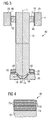
- Exemplary embodiments of the invention are explained in the following with the aid of schematic drawings. These are as follows:
- Figure 1,
- an injection valve in a longitudinal section view,
- Figure 2,
- an enlarged and detailed view of a first embodiment of a valve assembly of the injection valve in a longitudinal section view,
- Figure 3,
- an enlarged and detailed view of a second embodiment of the valve assembly of the injection valve in a longitudinal section view, and
- Figure 4,
- a surface layer of the valve assembly of the injection valve in a sectional view.
- Elements of the same design and function that appear in different illustrations are identified by the same reference characters.
- An injection valve 82 (
figure 1 ) that is in particular suitable for dosing fuel to an internal combustion engine comprises avalve assembly 80 and ahousing 6. - The
valve assembly 80 comprises avalve body 4 with a central longitudinal axis L and a cavity 8 which takes in avalve needle 10. Thevalve body 4 comprises aninlet tube 2. - The
valve needle 10 comprises anarmature 12. The cavity 8 of thevalve body 4 forms aninner surface 18. - In the
inlet tube 2 and in thearmature 12, arecess 16 is provided. Aspring 14 is arranged in therecess 16 of theinlet tube 2 and thearmature 12. Preferably, it rests on a spring seat being formed by ananti-bounce disk 20. By this, thespring 14 is mechanically coupled to theneedle 10. An adjustingtube 22 is provided in therecess 16 of theinlet tube 2. The adjustingtube 22 forms a further seat for thespring 14 and may be axially moved during the manufacturing process of the fluid injection valve in order to preload thespring 14 in a desired way. - In a closing position of the
valve needle 10, it sealingly rests on aneedle seat 46 of aseat body 26, by this preventing a fluid flow through at least oneinjection nozzle 24. Theinjection nozzle 24 may be, for example, an injection hole. However, it may also be of some other type suitable for dosing fluid. Theseat body 26 may be made in one part with thevalve body 4 or be a separate part. - Furthermore, a
lower guide element 28 is provided for guiding theneedle 10 and aswirl disk 30 for giving the fluid a radial velocity component. - In addition to that, the
valve body 4 comprises anupper guide element 29 for guiding thevalve needle 10, in particular thearmature 12 of thevalve needle 10. - The
injection valve 82 is provided with anactuator unit 40 that comprises preferably an electromagnetic actuator with acoil 36 which is preferably over-molded. Avalve body shell 38, thearmature 12 and theinlet tube 2 are forming an electromagnetic circuit. Theactuator unit 40 may, however, also comprise another type of actuator, which is known to persons skilled in the art for that purpose. Such an actuator may be, for example, a piezoelectric actuator. - The
valve assembly 80 has afluid inlet portion 42 which is provided in thevalve body 4. Thefluid inlet portion 42 communicates with afluid outlet portion 44 which is part of the cavity 8 near theseat body 26. - The
valve needle 10 has a seat part 50 being adjacent to theseat body 26. - In the embodiment shown in
figure 2 , the seat part 50 has a sealingportion 52. In the closing position of thevalve assembly 80 the sealingportion 52 rests on theneedle seat 46. The sealingportion 52 of thevalve needle 10 has asurface layer 48. Thesurface layer 48 of the sealingportion 52 has a thickness of 0.8 µm to 3.0 µm. - As can be seen in
figure 4 , thesurface layer 48 is built up as a stack of layers comprising tungsten carbide layers 70 and carbon layers 72. Preferably, the tungsten carbide layers and the carbon layers 72 are alternating as shown infigure 4 . Preferably, each of the tungsten carbide layers 70 and the carbon layers 72 has a thickness of a few atoms. Additionally, thesurface layer 48 has achromium layer 74 which forms an adhesive layer of thesurface layer 48 to mechanically coupling thesurface layer 48 to thevalve needle 10. In a preferred embodiment, thechromium layer 74 and the adjacent tungsten carbide layer 70 are forming a common intermediate layer which enables a good adhesion between thevalve needle 10 and thefurther layers 70, 72 of thesurface layer 48. - Furthermore, the
armature 12 of thevalve needle 10 has afront surface area 58 which faces away from thefluid outlet portion 44. Thefront surface area 58 is facing the correspondinginner surface 18 of theinlet tube 2. Thefront surface area 58 has asurface layer 48 with the tungsten carbide layers 70 and the carbon layers 72. Thesurface layer 48 of thefront surface area 58 has a thickness of 0.5 µm up to 1.5 µm. - Furthermore, the
valve needle 10 has aslide area 54 near the seat part 50 and thearmature 12 of thevalve needle 10 has aslide area 56. Theslide area 54 near the seat part 50 is in a sliding contact with thelower guide element 28, theslide area 56 of thearmature 12 is in a sliding contact with theupper guide element 29. Theslide areas valve needle 10 have asurface layer 48 each, with the tungsten layers 70 and the carbon layers 72. Thesurface layer 48 of theslide area 54 being in sliding contact with thelower guide element 28 has a thickness of 0.8 µm to 2.0 µm. Thesurface layer 48 of theslide area 56 of thearmature 12 has a thickness of 0.5 µm to 2.0 µm. - In the embodiment of the
valve assembly 80 shown infigure 3 , thelower guide element 28 has aslide area 60 with thesurface layer 48. Theupper guide element 29 has aslide area 62 with thesurface layer 48. A further of the surface layers 48 is arranged on theneedle seat 46 of theseat body 26. Thesurface layer 48 of theneedle seat 46 has a thickness of 0.8 um to 3.0 µm. Thesurface layer 48 of theinner surface 18 facing thefront surface area 58 has a thickness of 0.4 µm to 1.5 µm. The surface layer on thelower guide element 28 has a thickness of 0.8 µm to 2.0 µm. Thesurface layer 48 on theupper guide element 29 has a thickness of 0.5 µm to 2.0 µm. - In the following, the function of the injection valve is described in detail:
- The fluid is led from the
inlet tube 2 to thehollow valve needle 10 and then through anorifice 76 in thevalve needle 10 to thefluid inlet portion 42 and thefluid outlet portion 44. - The
spring 14 forces thevalve needle 10 via theanti-bounce disk 20 towards theactuator unit 40. In the case when theactuator unit 40 is de-energized thespring 14 can force thevalve needle 10 to move in axial direction in its closing position. It is depending on the force balance between the force on thevalve needle 10 caused by theactuator unit 40 and the force on thevalve needle 10 caused by thespring 14 whether thevalve needle 10 is in its closing position or not. - In the closing position of the
valve needle 10 the seat part 50 of thevalve needle 10 sealingly rests on theneedle seat 46 of theseat body 26 and consequently a fluid flow through thefluid outlet portion 44 and theinjection nozzle 24 is prevented. - In the case that the
actuator unit 40 gets energized, theactuator unit 40 may exert a force on thevalve needle 10. Thevalve needle 10 is able to move in axial direction out of the closing position. Outside of the closing position of thevalve needle 10, there is a gap between theseat body 26 and thevalve needle 10 which enables a fluid flow through theinjection nozzle 24. - The movement of the
valve needle 10 results in an impact of thevalve needle 10 on thevalve body 4. In particular, the seat part 50 of thevalve needle 10 forms an impact section relative to theneedle seat 46 of theseat body 26. By coating the sealingportion 52 of thevalve needle 10 and/or theneedle seat 46 of theseat body 26, good wearing characteristics of the seat part 50 of thevalve needle 10 and/or theseat body 26 can be obtained. Furthermore, the friction coefficient between thevalve needle 10 and theseat body 26 is very low. By this, leakage failures of thevalve assembly 80 can be kept low and a high lifetime of thevalve assembly 80 is possible. - Covering the
front surface area 58 of thevalve needle 10 with thesurface layer 48 allows keeping the wearing effect on theinner surface 18 facing thefront surface area 58 very small. - The coating of the
slide areas valve needle 10 with thesurface layer 48 enables a low sliding coefficient between thevalve needle 10 and theguide elements valve body 4. By this, the wearing effect of thelower guide element 28 and theupper guide element 29 can be kept small. - In general, it is preferred that the thickness of the
surface layer 48 on the seat part 50 of thevalve needle 10 is the highest compared with the further surface layers 48 on thevalve needle 10. This is due to the very high load in the case of the impact of thevalve needle 10 on theseat body 26. The thickness of thesurface layer 48 on thefront surface area 58 of thevalve needle 10 is low compared with the further surface layers 48. Preferably, the thickness of the surface layers 48 of theslide areas valve 10 is higher than the thickness of thesurface layer 48 of thefront surface area 58 of thevalve needle 10 and is lower than the thickness of thesurface layer 48 of the seat part 50 of thevalve needle 10. - Corresponding to this, preferably the thickness of the
surface layer 48 on theseat body 26 is the highest compared with the further surface layers 48 on theinner surface 18 of thevalve body 4. The thickness of thesurface layer 48 on theinner surface 18 facing thefront surface area 58 is low compared with the further surface layers 48 on theinner surface 18. The thickness of the surface layers 48 on theguide elements inner surface 18 facing thefront surface area 58 and is lower than the thickness of thesurface layer 48 of theseat body 26. - The selection of an appropriate thickness of the different surface layers 48 enables to obtain a good result for the wearing conditions of the valve needle and/or the
valve body 4 and the sliding conditions between thevalve needle 10 and thevalve body 4 in connection with only small changes of the geometry of thevalve needle 10 or thevalve body 4.
Claims (10)
- Valve assembly (80) of an injection valve (82), the valve assembly (80) comprising- a valve body (4) including a central longitudinal axis (L), the valve body (4) comprising a cavity (8) forming an inner surface (18) of the valve body (4), the cavity (8) having a fluid inlet portion (42), and a fluid outlet portion (44),- a valve needle (10) axially movable in the cavity (8), the valve needle (10) preventing a fluid flow through the fluid outlet portion (44) in a closing position and releasing the fluid flow through the fluid outlet portion (44) in further positions, the valve needle (10) and/or the inner surface (18) of the valve body (4) having a surface layer (48) comprising a tungsten carbide layer (70) and a carbon layer (72).
- Valve assembly (80) in accordance with claim 1, with the valve body (4) comprising a needle seat (46), the valve needle (10) comprising a seat part (50) with a sealing portion (52), the sealing portion (52) resting on the needle seat (46) in the closing position, with the sealing portion (52) of the valve needle (10) and/or the needle seat (46) comprising the surface layer (48).
- Valve assembly (80) in accordance with claim 2, the surface layer (48) of the sealing portion (52) and/or the surface layer (48) of the needle seat (46) having a thickness of up to 3 µm.
- Valve assembly (80) in accordance with one of the preceding claims, with the valve needle (10) comprising a front surface area (58) facing away from the fluid outlet portion (44) and being enabled to be in contact with a corresponding inner surface (18) of the valve body (4), with the front surface area (58) and/or the corresponding inner surface (18) comprising the surface layer (48).
- Valve assembly (80) in accordance with claim 4, the surface layer (48) of the front surface area (58) and/or the surface layer (48) of the corresponding inner surface (18) having a thickness of 0.5 µm up to 1.5 µm.
- Valve assembly (80) in accordance with one of the preceding claims, with the valve body (4) comprising a guide element (28, 29) guiding the valve needle (10) in axial direction, the valve needle (10) comprising a slide area (54, 56) being in a sliding contact with the guide element (28, 29), with the slide area (54, 56) of the valve needle (10) and/or the guide element (28, 29) comprising the surface layer (48).
- Valve assembly (80) in accordance with claim 6, the surface layer (48) of the slide area (54, 56) and/or the surface layer (48) of the guide element (28, 29) having a thickness of 0.5 µm to 2 µm.
- Valve assembly (80) in accordance with one of the preceding claims, with the surface layer (48) comprising a plurality of tungsten carbide layers (70) and carbon layers (72).
- Valve assembly (80) in accordance with one of the preceding claims, with the surface layer (48) comprising a chromium layer (74).
- Injection valve (82) with a housing (6), an actuator unit (40) and a valve assembly (80) according to one of the preceding claims.
Priority Applications (2)
| Application Number | Priority Date | Filing Date | Title |
|---|---|---|---|
| EP07023476.0A EP2067983B1 (en) | 2007-12-04 | 2007-12-04 | Valve assembly for an injection valve and injection valve |
| US12/327,095 US7909270B2 (en) | 2007-12-04 | 2008-12-03 | Valve assembly for an injection valve and injection valve |
Applications Claiming Priority (1)
| Application Number | Priority Date | Filing Date | Title |
|---|---|---|---|
| EP07023476.0A EP2067983B1 (en) | 2007-12-04 | 2007-12-04 | Valve assembly for an injection valve and injection valve |
Publications (2)
| Publication Number | Publication Date |
|---|---|
| EP2067983A1 true EP2067983A1 (en) | 2009-06-10 |
| EP2067983B1 EP2067983B1 (en) | 2014-07-16 |
Family
ID=39133810
Family Applications (1)
| Application Number | Title | Priority Date | Filing Date |
|---|---|---|---|
| EP07023476.0A Ceased EP2067983B1 (en) | 2007-12-04 | 2007-12-04 | Valve assembly for an injection valve and injection valve |
Country Status (2)
| Country | Link |
|---|---|
| US (1) | US7909270B2 (en) |
| EP (1) | EP2067983B1 (en) |
Cited By (4)
| Publication number | Priority date | Publication date | Assignee | Title |
|---|---|---|---|---|
| WO2010012704A1 (en) * | 2008-07-28 | 2010-02-04 | Robert Bosch Gmbh | Anti-wear layer arrangement and component comprising an anti-wear layer arrangement |
| EP2439400A1 (en) * | 2010-10-05 | 2012-04-11 | Continental Automotive GmbH | Valve assembly for an injection valve and injection valve |
| WO2014139706A1 (en) * | 2013-03-11 | 2014-09-18 | Robert Bosch Gmbh | Valve for controlling a fluid with increased sealing action |
| WO2019141863A1 (en) * | 2018-01-22 | 2019-07-25 | Liebherr-Components Deggendorf Gmbh | Seat plate for an injector and method for producing a seat plate of this type |
Families Citing this family (4)
| Publication number | Priority date | Publication date | Assignee | Title |
|---|---|---|---|---|
| US9346074B2 (en) | 2010-09-13 | 2016-05-24 | Nordson Corporation | Conformal coating applicator and method |
| WO2015036244A1 (en) * | 2013-09-13 | 2015-03-19 | Continental Automotive Gmbh | Fluid injector |
| US10626834B2 (en) * | 2016-05-03 | 2020-04-21 | GM Global Technology Operations LLC | Fuel injector for an internal combustion engine |
| JP2019100208A (en) * | 2017-11-29 | 2019-06-24 | 株式会社デンソー | Fuel injection valve |
Citations (5)
| Publication number | Priority date | Publication date | Assignee | Title |
|---|---|---|---|---|
| US5783261A (en) * | 1996-07-11 | 1998-07-21 | Ford Global Technologies, Inc. | Using a coated fuel injector and method of making |
| WO2001061182A1 (en) | 2000-02-15 | 2001-08-23 | Caterpillar Inc. | Thin film coatings for fuel injector components |
| EP1150004A2 (en) * | 2000-04-28 | 2001-10-31 | Delphi Technologies, Inc. | Coated fuel injector valve |
| DE10038954A1 (en) | 2000-08-09 | 2002-02-28 | Siemens Ag | Valve used as an injection valve for a common rail injection system comprises a valve body with a valve body seat, and a valve needle guided in the valve body with a valve needle seat to control an opening |
| EP1793120A1 (en) | 2005-12-02 | 2007-06-06 | Siemens Aktiengesellschaft | Valve assembly for an injection valve |
Family Cites Families (8)
| Publication number | Priority date | Publication date | Assignee | Title |
|---|---|---|---|---|
| US5731045A (en) * | 1996-01-26 | 1998-03-24 | Southwest Research Institute | Application of diamond-like carbon coatings to cobalt-cemented tungsten carbide components |
| US6802457B1 (en) * | 1998-09-21 | 2004-10-12 | Caterpillar Inc | Coatings for use in fuel system components |
| US6715693B1 (en) * | 2000-02-15 | 2004-04-06 | Caterpillar Inc | Thin film coating for fuel injector components |
| JP4300762B2 (en) * | 2002-07-10 | 2009-07-22 | 日新電機株式会社 | Carbon film-coated article and method for producing the same |
| US7028928B2 (en) * | 2002-12-02 | 2006-04-18 | Caterpillar Inc. | Hard coating of an impact surface of a solenoid actuator and fuel injector using same |
| DE102004002678B4 (en) * | 2004-01-19 | 2005-12-01 | Siemens Ag | Valve needle and valve |
| US7244493B2 (en) * | 2004-11-12 | 2007-07-17 | Delphi Technologies, Inc. | Coated article |
| US20090026292A1 (en) * | 2007-07-27 | 2009-01-29 | Caterpillar Inc. | Coatings for use in fuel system components |
-
2007
- 2007-12-04 EP EP07023476.0A patent/EP2067983B1/en not_active Ceased
-
2008
- 2008-12-03 US US12/327,095 patent/US7909270B2/en not_active Expired - Fee Related
Patent Citations (5)
| Publication number | Priority date | Publication date | Assignee | Title |
|---|---|---|---|---|
| US5783261A (en) * | 1996-07-11 | 1998-07-21 | Ford Global Technologies, Inc. | Using a coated fuel injector and method of making |
| WO2001061182A1 (en) | 2000-02-15 | 2001-08-23 | Caterpillar Inc. | Thin film coatings for fuel injector components |
| EP1150004A2 (en) * | 2000-04-28 | 2001-10-31 | Delphi Technologies, Inc. | Coated fuel injector valve |
| DE10038954A1 (en) | 2000-08-09 | 2002-02-28 | Siemens Ag | Valve used as an injection valve for a common rail injection system comprises a valve body with a valve body seat, and a valve needle guided in the valve body with a valve needle seat to control an opening |
| EP1793120A1 (en) | 2005-12-02 | 2007-06-06 | Siemens Aktiengesellschaft | Valve assembly for an injection valve |
Cited By (5)
| Publication number | Priority date | Publication date | Assignee | Title |
|---|---|---|---|---|
| WO2010012704A1 (en) * | 2008-07-28 | 2010-02-04 | Robert Bosch Gmbh | Anti-wear layer arrangement and component comprising an anti-wear layer arrangement |
| EP2439400A1 (en) * | 2010-10-05 | 2012-04-11 | Continental Automotive GmbH | Valve assembly for an injection valve and injection valve |
| WO2014139706A1 (en) * | 2013-03-11 | 2014-09-18 | Robert Bosch Gmbh | Valve for controlling a fluid with increased sealing action |
| US10125735B2 (en) | 2013-03-11 | 2018-11-13 | Robert Bosch Gmbh | Valve for controlling a fluid with increased sealing action |
| WO2019141863A1 (en) * | 2018-01-22 | 2019-07-25 | Liebherr-Components Deggendorf Gmbh | Seat plate for an injector and method for producing a seat plate of this type |
Also Published As
| Publication number | Publication date |
|---|---|
| EP2067983B1 (en) | 2014-07-16 |
| US7909270B2 (en) | 2011-03-22 |
| US20090140079A1 (en) | 2009-06-04 |
Similar Documents
| Publication | Publication Date | Title |
|---|---|---|
| US7909270B2 (en) | Valve assembly for an injection valve and injection valve | |
| EP2436910B1 (en) | Valve assembly for an injection valve and injection valve | |
| EP2535552B1 (en) | Valve assembly for an injection valve and injection valve | |
| EP2333297B1 (en) | Valve assembly for an injection valve and injection valve | |
| EP1150004B1 (en) | Coated fuel injector valve | |
| EP2852753A1 (en) | Valve assembly for an injection valve and injection valve | |
| EP2246554B1 (en) | Valve assembly for an injection valve and injection valve | |
| CN104583576B (en) | Valve assemblies and injection valves for injection valves | |
| US9297343B2 (en) | Needle for needle valve | |
| EP2149699B1 (en) | Fuel injector | |
| EP2378106A1 (en) | Valve assembly for an injection valve and injection valve | |
| EP2375051A1 (en) | Valve assembly for an injection valve and injection valve | |
| EP2719886B1 (en) | Valve assembly for an injection valve | |
| EP2439400A1 (en) | Valve assembly for an injection valve and injection valve | |
| EP2466109A1 (en) | Valve assembly for an injection valve and injection valve | |
| EP2282042B1 (en) | Valve assembly and injection valve | |
| US20080023578A1 (en) | Valve Assembly for an Injection Valve and Injection Valve | |
| EP2811148B1 (en) | Fluid injector for a combustion engine | |
| EP1811166B1 (en) | Valve assembly for an injection valve and injection valve | |
| WO2009141839A1 (en) | Valve assembly for an injection valve and injection valve | |
| EP1816342A1 (en) | Valve assembly for an injection valve and injection valve | |
| EP2354531A1 (en) | Valve assembly for an injection valve and injection valve | |
| CN111042968A (en) | Valve assembly for an injection valve and fuel injection valve | |
| EP2426350A1 (en) | Valve assembly for an injection valve and injection valve | |
| EP1793120A1 (en) | Valve assembly for an injection valve |
Legal Events
| Date | Code | Title | Description |
|---|---|---|---|
| PUAI | Public reference made under article 153(3) epc to a published international application that has entered the european phase |
Free format text: ORIGINAL CODE: 0009012 |
|
| AK | Designated contracting states |
Kind code of ref document: A1 Designated state(s): AT BE BG CH CY CZ DE DK EE ES FI FR GB GR HU IE IS IT LI LT LU LV MC MT NL PL PT RO SE SI SK TR |
|
| AX | Request for extension of the european patent |
Extension state: AL BA HR MK RS |
|
| 17P | Request for examination filed |
Effective date: 20091210 |
|
| AKX | Designation fees paid |
Designated state(s): DE FR IT |
|
| 17Q | First examination report despatched |
Effective date: 20101227 |
|
| RIC1 | Information provided on ipc code assigned before grant |
Ipc: F02M 61/12 20060101ALI20120801BHEP Ipc: F02M 61/16 20060101AFI20120801BHEP Ipc: F02M 51/06 20060101ALI20120801BHEP Ipc: F02M 61/18 20060101ALI20120801BHEP |
|
| REG | Reference to a national code |
Ref country code: DE Ref legal event code: R079 Ref document number: 602007037618 Country of ref document: DE Free format text: PREVIOUS MAIN CLASS: F02M0061160000 Ipc: C23C0028040000 |
|
| RIC1 | Information provided on ipc code assigned before grant |
Ipc: F02M 61/12 20060101ALI20131212BHEP Ipc: C23C 28/04 20060101AFI20131212BHEP Ipc: F02M 61/18 20060101ALI20131212BHEP Ipc: F02M 61/16 20060101ALI20131212BHEP Ipc: C23C 28/00 20060101ALI20131212BHEP Ipc: F02M 51/06 20060101ALI20131212BHEP |
|
| GRAP | Despatch of communication of intention to grant a patent |
Free format text: ORIGINAL CODE: EPIDOSNIGR1 |
|
| INTG | Intention to grant announced |
Effective date: 20140203 |
|
| GRAS | Grant fee paid |
Free format text: ORIGINAL CODE: EPIDOSNIGR3 |
|
| GRAA | (expected) grant |
Free format text: ORIGINAL CODE: 0009210 |
|
| AK | Designated contracting states |
Kind code of ref document: B1 Designated state(s): DE FR IT |
|
| REG | Reference to a national code |
Ref country code: DE Ref legal event code: R096 Ref document number: 602007037618 Country of ref document: DE Effective date: 20140821 |
|
| REG | Reference to a national code |
Ref country code: DE Ref legal event code: R097 Ref document number: 602007037618 Country of ref document: DE |
|
| PLBE | No opposition filed within time limit |
Free format text: ORIGINAL CODE: 0009261 |
|
| STAA | Information on the status of an ep patent application or granted ep patent |
Free format text: STATUS: NO OPPOSITION FILED WITHIN TIME LIMIT |
|
| 26N | No opposition filed |
Effective date: 20150417 |
|
| REG | Reference to a national code |
Ref country code: FR Ref legal event code: PLFP Year of fee payment: 9 |
|
| REG | Reference to a national code |
Ref country code: FR Ref legal event code: PLFP Year of fee payment: 10 |
|
| REG | Reference to a national code |
Ref country code: FR Ref legal event code: PLFP Year of fee payment: 11 |
|
| REG | Reference to a national code |
Ref country code: DE Ref legal event code: R084 Ref document number: 602007037618 Country of ref document: DE |
|
| REG | Reference to a national code |
Ref country code: DE Ref legal event code: R081 Ref document number: 602007037618 Country of ref document: DE Owner name: VITESCO TECHNOLOGIES GMBH, DE Free format text: FORMER OWNER: CONTINENTAL AUTOMOTIVE GMBH, 30165 HANNOVER, DE |
|
| REG | Reference to a national code |
Ref country code: DE Ref legal event code: R081 Ref document number: 602007037618 Country of ref document: DE Owner name: VITESCO TECHNOLOGIES GMBH, DE Free format text: FORMER OWNER: VITESCO TECHNOLOGIES GMBH, 30165 HANNOVER, DE |
|
| P01 | Opt-out of the competence of the unified patent court (upc) registered |
Effective date: 20230530 |
|
| PGFP | Annual fee paid to national office [announced via postgrant information from national office to epo] |
Ref country code: IT Payment date: 20231228 Year of fee payment: 17 Ref country code: FR Payment date: 20231221 Year of fee payment: 17 Ref country code: DE Payment date: 20231231 Year of fee payment: 17 |
|
| REG | Reference to a national code |
Ref country code: DE Ref legal event code: R119 Ref document number: 602007037618 Country of ref document: DE |
|
| PG25 | Lapsed in a contracting state [announced via postgrant information from national office to epo] |
Ref country code: DE Free format text: LAPSE BECAUSE OF NON-PAYMENT OF DUE FEES Effective date: 20250701 |
|
| PG25 | Lapsed in a contracting state [announced via postgrant information from national office to epo] |
Ref country code: IT Free format text: LAPSE BECAUSE OF NON-PAYMENT OF DUE FEES Effective date: 20241204 |
|
| PG25 | Lapsed in a contracting state [announced via postgrant information from national office to epo] |
Ref country code: FR Free format text: LAPSE BECAUSE OF NON-PAYMENT OF DUE FEES Effective date: 20241231 |