EP2067709A2 - Two-part flat pallet - Google Patents
Two-part flat pallet Download PDFInfo
- Publication number
- EP2067709A2 EP2067709A2 EP08105748A EP08105748A EP2067709A2 EP 2067709 A2 EP2067709 A2 EP 2067709A2 EP 08105748 A EP08105748 A EP 08105748A EP 08105748 A EP08105748 A EP 08105748A EP 2067709 A2 EP2067709 A2 EP 2067709A2
- Authority
- EP
- European Patent Office
- Prior art keywords
- plate
- flat pallet
- plates
- coupling means
- handle
- Prior art date
- Legal status (The legal status is an assumption and is not a legal conclusion. Google has not performed a legal analysis and makes no representation as to the accuracy of the status listed.)
- Granted
Links
- 230000008878 coupling Effects 0.000 claims abstract description 18
- 238000010168 coupling process Methods 0.000 claims abstract description 18
- 238000005859 coupling reaction Methods 0.000 claims abstract description 18
- 230000000295 complement effect Effects 0.000 claims abstract description 4
- 229910000831 Steel Inorganic materials 0.000 claims description 8
- 239000010959 steel Substances 0.000 claims description 8
- 238000003860 storage Methods 0.000 claims description 6
- 229920001903 high density polyethylene Polymers 0.000 description 2
- 239000004700 high-density polyethylene Substances 0.000 description 2
- 238000004519 manufacturing process Methods 0.000 description 2
- 238000000034 method Methods 0.000 description 2
- 239000000969 carrier Substances 0.000 description 1
- 238000004140 cleaning Methods 0.000 description 1
- 230000001419 dependent effect Effects 0.000 description 1
- 238000006073 displacement reaction Methods 0.000 description 1
- 238000009826 distribution Methods 0.000 description 1
- 239000005022 packaging material Substances 0.000 description 1
- 239000004033 plastic Substances 0.000 description 1
- 229920003023 plastic Polymers 0.000 description 1
- 230000002787 reinforcement Effects 0.000 description 1
- 238000012216 screening Methods 0.000 description 1
- 230000007704 transition Effects 0.000 description 1
Images

Classifications
-
- B—PERFORMING OPERATIONS; TRANSPORTING
- B65—CONVEYING; PACKING; STORING; HANDLING THIN OR FILAMENTARY MATERIAL
- B65D—CONTAINERS FOR STORAGE OR TRANSPORT OF ARTICLES OR MATERIALS, e.g. BAGS, BARRELS, BOTTLES, BOXES, CANS, CARTONS, CRATES, DRUMS, JARS, TANKS, HOPPERS, FORWARDING CONTAINERS; ACCESSORIES, CLOSURES, OR FITTINGS THEREFOR; PACKAGING ELEMENTS; PACKAGES
- B65D19/00—Pallets or like platforms, with or without side walls, for supporting loads to be lifted or lowered
- B65D19/0002—Platforms, i.e. load supporting devices without provision for handling by a forklift
-
- B—PERFORMING OPERATIONS; TRANSPORTING
- B65—CONVEYING; PACKING; STORING; HANDLING THIN OR FILAMENTARY MATERIAL
- B65D—CONTAINERS FOR STORAGE OR TRANSPORT OF ARTICLES OR MATERIALS, e.g. BAGS, BARRELS, BOTTLES, BOXES, CANS, CARTONS, CRATES, DRUMS, JARS, TANKS, HOPPERS, FORWARDING CONTAINERS; ACCESSORIES, CLOSURES, OR FITTINGS THEREFOR; PACKAGING ELEMENTS; PACKAGES
- B65D19/00—Pallets or like platforms, with or without side walls, for supporting loads to be lifted or lowered
- B65D19/0004—Rigid pallets without side walls
- B65D19/0006—Rigid pallets without side walls the load supporting surface being made of a single element
- B65D19/0008—Rigid pallets without side walls the load supporting surface being made of a single element forming a continuous plane contact surface
- B65D19/001—Rigid pallets without side walls the load supporting surface being made of a single element forming a continuous plane contact surface the base surface being made of a single element
- B65D19/0014—Rigid pallets without side walls the load supporting surface being made of a single element forming a continuous plane contact surface the base surface being made of a single element forming discontinuous or non-planar contact surfaces
-
- B—PERFORMING OPERATIONS; TRANSPORTING
- B65—CONVEYING; PACKING; STORING; HANDLING THIN OR FILAMENTARY MATERIAL
- B65D—CONTAINERS FOR STORAGE OR TRANSPORT OF ARTICLES OR MATERIALS, e.g. BAGS, BARRELS, BOTTLES, BOXES, CANS, CARTONS, CRATES, DRUMS, JARS, TANKS, HOPPERS, FORWARDING CONTAINERS; ACCESSORIES, CLOSURES, OR FITTINGS THEREFOR; PACKAGING ELEMENTS; PACKAGES
- B65D2519/00—Pallets or like platforms, with or without side walls, for supporting loads to be lifted or lowered
- B65D2519/00004—Details relating to pallets
- B65D2519/00009—Materials
- B65D2519/00014—Materials for the load supporting surface
- B65D2519/00034—Plastic
-
- B—PERFORMING OPERATIONS; TRANSPORTING
- B65—CONVEYING; PACKING; STORING; HANDLING THIN OR FILAMENTARY MATERIAL
- B65D—CONTAINERS FOR STORAGE OR TRANSPORT OF ARTICLES OR MATERIALS, e.g. BAGS, BARRELS, BOTTLES, BOXES, CANS, CARTONS, CRATES, DRUMS, JARS, TANKS, HOPPERS, FORWARDING CONTAINERS; ACCESSORIES, CLOSURES, OR FITTINGS THEREFOR; PACKAGING ELEMENTS; PACKAGES
- B65D2519/00—Pallets or like platforms, with or without side walls, for supporting loads to be lifted or lowered
- B65D2519/00004—Details relating to pallets
- B65D2519/00009—Materials
- B65D2519/00049—Materials for the base surface
- B65D2519/00069—Plastic
-
- B—PERFORMING OPERATIONS; TRANSPORTING
- B65—CONVEYING; PACKING; STORING; HANDLING THIN OR FILAMENTARY MATERIAL
- B65D—CONTAINERS FOR STORAGE OR TRANSPORT OF ARTICLES OR MATERIALS, e.g. BAGS, BARRELS, BOTTLES, BOXES, CANS, CARTONS, CRATES, DRUMS, JARS, TANKS, HOPPERS, FORWARDING CONTAINERS; ACCESSORIES, CLOSURES, OR FITTINGS THEREFOR; PACKAGING ELEMENTS; PACKAGES
- B65D2519/00—Pallets or like platforms, with or without side walls, for supporting loads to be lifted or lowered
- B65D2519/00004—Details relating to pallets
- B65D2519/00009—Materials
- B65D2519/00119—Materials for the construction of the reinforcements
- B65D2519/00129—Metal
-
- B—PERFORMING OPERATIONS; TRANSPORTING
- B65—CONVEYING; PACKING; STORING; HANDLING THIN OR FILAMENTARY MATERIAL
- B65D—CONTAINERS FOR STORAGE OR TRANSPORT OF ARTICLES OR MATERIALS, e.g. BAGS, BARRELS, BOTTLES, BOXES, CANS, CARTONS, CRATES, DRUMS, JARS, TANKS, HOPPERS, FORWARDING CONTAINERS; ACCESSORIES, CLOSURES, OR FITTINGS THEREFOR; PACKAGING ELEMENTS; PACKAGES
- B65D2519/00—Pallets or like platforms, with or without side walls, for supporting loads to be lifted or lowered
- B65D2519/00004—Details relating to pallets
- B65D2519/00258—Overall construction
- B65D2519/00263—Overall construction of the pallet
- B65D2519/00268—Overall construction of the pallet made of one piece
-
- B—PERFORMING OPERATIONS; TRANSPORTING
- B65—CONVEYING; PACKING; STORING; HANDLING THIN OR FILAMENTARY MATERIAL
- B65D—CONTAINERS FOR STORAGE OR TRANSPORT OF ARTICLES OR MATERIALS, e.g. BAGS, BARRELS, BOTTLES, BOXES, CANS, CARTONS, CRATES, DRUMS, JARS, TANKS, HOPPERS, FORWARDING CONTAINERS; ACCESSORIES, CLOSURES, OR FITTINGS THEREFOR; PACKAGING ELEMENTS; PACKAGES
- B65D2519/00—Pallets or like platforms, with or without side walls, for supporting loads to be lifted or lowered
- B65D2519/00004—Details relating to pallets
- B65D2519/00258—Overall construction
- B65D2519/00283—Overall construction of the load supporting surface
- B65D2519/00288—Overall construction of the load supporting surface made of one piece
-
- B—PERFORMING OPERATIONS; TRANSPORTING
- B65—CONVEYING; PACKING; STORING; HANDLING THIN OR FILAMENTARY MATERIAL
- B65D—CONTAINERS FOR STORAGE OR TRANSPORT OF ARTICLES OR MATERIALS, e.g. BAGS, BARRELS, BOTTLES, BOXES, CANS, CARTONS, CRATES, DRUMS, JARS, TANKS, HOPPERS, FORWARDING CONTAINERS; ACCESSORIES, CLOSURES, OR FITTINGS THEREFOR; PACKAGING ELEMENTS; PACKAGES
- B65D2519/00—Pallets or like platforms, with or without side walls, for supporting loads to be lifted or lowered
- B65D2519/00004—Details relating to pallets
- B65D2519/00258—Overall construction
- B65D2519/00313—Overall construction of the base surface
- B65D2519/00328—Overall construction of the base surface shape of the contact surface of the base
- B65D2519/00348—Overall construction of the base surface shape of the contact surface of the base contact surface of other form
-
- B—PERFORMING OPERATIONS; TRANSPORTING
- B65—CONVEYING; PACKING; STORING; HANDLING THIN OR FILAMENTARY MATERIAL
- B65D—CONTAINERS FOR STORAGE OR TRANSPORT OF ARTICLES OR MATERIALS, e.g. BAGS, BARRELS, BOTTLES, BOXES, CANS, CARTONS, CRATES, DRUMS, JARS, TANKS, HOPPERS, FORWARDING CONTAINERS; ACCESSORIES, CLOSURES, OR FITTINGS THEREFOR; PACKAGING ELEMENTS; PACKAGES
- B65D2519/00—Pallets or like platforms, with or without side walls, for supporting loads to be lifted or lowered
- B65D2519/00004—Details relating to pallets
- B65D2519/00258—Overall construction
- B65D2519/00398—Overall construction reinforcements
- B65D2519/00402—Integral, e.g. ribs
- B65D2519/00412—Integral, e.g. ribs on the base surface
-
- B—PERFORMING OPERATIONS; TRANSPORTING
- B65—CONVEYING; PACKING; STORING; HANDLING THIN OR FILAMENTARY MATERIAL
- B65D—CONTAINERS FOR STORAGE OR TRANSPORT OF ARTICLES OR MATERIALS, e.g. BAGS, BARRELS, BOTTLES, BOXES, CANS, CARTONS, CRATES, DRUMS, JARS, TANKS, HOPPERS, FORWARDING CONTAINERS; ACCESSORIES, CLOSURES, OR FITTINGS THEREFOR; PACKAGING ELEMENTS; PACKAGES
- B65D2519/00—Pallets or like platforms, with or without side walls, for supporting loads to be lifted or lowered
- B65D2519/00004—Details relating to pallets
- B65D2519/00258—Overall construction
- B65D2519/00398—Overall construction reinforcements
- B65D2519/00432—Non-integral, e.g. inserts
-
- B—PERFORMING OPERATIONS; TRANSPORTING
- B65—CONVEYING; PACKING; STORING; HANDLING THIN OR FILAMENTARY MATERIAL
- B65D—CONTAINERS FOR STORAGE OR TRANSPORT OF ARTICLES OR MATERIALS, e.g. BAGS, BARRELS, BOTTLES, BOXES, CANS, CARTONS, CRATES, DRUMS, JARS, TANKS, HOPPERS, FORWARDING CONTAINERS; ACCESSORIES, CLOSURES, OR FITTINGS THEREFOR; PACKAGING ELEMENTS; PACKAGES
- B65D2519/00—Pallets or like platforms, with or without side walls, for supporting loads to be lifted or lowered
- B65D2519/00004—Details relating to pallets
- B65D2519/00736—Details
- B65D2519/00741—Dimensional aspects of the pallet
- B65D2519/00746—Dimensional aspects of the pallet divisible into sub-pallets of smaller dimensions
-
- B—PERFORMING OPERATIONS; TRANSPORTING
- B65—CONVEYING; PACKING; STORING; HANDLING THIN OR FILAMENTARY MATERIAL
- B65D—CONTAINERS FOR STORAGE OR TRANSPORT OF ARTICLES OR MATERIALS, e.g. BAGS, BARRELS, BOTTLES, BOXES, CANS, CARTONS, CRATES, DRUMS, JARS, TANKS, HOPPERS, FORWARDING CONTAINERS; ACCESSORIES, CLOSURES, OR FITTINGS THEREFOR; PACKAGING ELEMENTS; PACKAGES
- B65D2519/00—Pallets or like platforms, with or without side walls, for supporting loads to be lifted or lowered
- B65D2519/00004—Details relating to pallets
- B65D2519/00736—Details
- B65D2519/00935—Details with special means for nesting or stacking
- B65D2519/00955—Details with special means for nesting or stacking stackable
- B65D2519/0096—Details with special means for nesting or stacking stackable when empty
-
- Y—GENERAL TAGGING OF NEW TECHNOLOGICAL DEVELOPMENTS; GENERAL TAGGING OF CROSS-SECTIONAL TECHNOLOGIES SPANNING OVER SEVERAL SECTIONS OF THE IPC; TECHNICAL SUBJECTS COVERED BY FORMER USPC CROSS-REFERENCE ART COLLECTIONS [XRACs] AND DIGESTS
- Y10—TECHNICAL SUBJECTS COVERED BY FORMER USPC
- Y10T—TECHNICAL SUBJECTS COVERED BY FORMER US CLASSIFICATION
- Y10T29/00—Metal working
- Y10T29/49—Method of mechanical manufacture
- Y10T29/49826—Assembling or joining
Landscapes
- Engineering & Computer Science (AREA)
- Mechanical Engineering (AREA)
- Pallets (AREA)
- Stackable Containers (AREA)
Abstract
Description
Die Erfindung betrifft eine zweiteilige Flachpalette als Stückgutträger zur Handhabung und Lagerung von Stückgütern, bei dem jeweils ein oder mehrere Stückgüter auf der Flachpalette geladen und mit der Flachpalette transportiert und/oder abgestellt werden. Das Anwendungsgebiet der vorliegenden Vorrichtung betrifft den Bereich der Lager- und Verteilsysteme sowie Lagertechniken für StückgüterThe invention relates to a two-part flat pallet as cargo carriers for handling and storage of general cargo, loaded in each case one or more cargo on the flat pallet and transported to the flat pallet and / or parked. The field of application of the present device relates to the field of storage and distribution systems as well as storage techniques for piece goods
Bei der Lagerung von Stückgütern finden verschiedene Lagerungskonzepte Verwendung. So werden beispielsweise Stückgüter auf Einwegpaletten oder anderen Verpackungsmitteln angeliefert und auf Flachpaletten umgeladen. Die befüllten Flachpaletten werden anschliessend über Fördereinrichtungen zum Lagerplatz transportiert und dort abgestellt. Bei der Auslieferung der Stückgüter kommen diese vom Lager auf der Flachpalette zur Umladestation und werden dort von der Flachpalette händisch wieder umgeladen bzw. verladen. Bei Industriepaletten mit Abmessungen von etwa 1 m x 1.2 m ergibt sich das Problem, dass das händische Ent- und Beladen der Paletten sehr anstrengend und arbeitsintensiv ist. Die Stückgüter müssen aus einer Entfernung von bis zu über einen Meter von der Palette gehoben oder darauf abgestellt werden. Bei grösseren Stückgütern mit entsprechend grösserem Gewicht ist das zum Teil den Beladern nicht zumutbar.When storing piece goods different storage concepts are used. For example, piece goods are delivered on disposable pallets or other packaging materials and reloaded on flat pallets. The filled flat pallets are then transported by conveyor to the storage area and parked there. When delivering the piece goods they come from the warehouse on the flat pallet to the transfer station and are there manually reloaded or loaded from the flat pallet. For industrial pallets with dimensions of about 1 mx 1.2 m, the problem arises that the manual unloading and loading of the pallets is very tiring and labor-intensive. The piece goods must be lifted from a distance of over one meter from the pallet or placed on it. For larger piece goods with a correspondingly greater weight, this is partly unreasonable for the loaders.
Es ist daher die Aufgabe der vorliegenden Erfindung, eine Flachpalette der genannten Art zu schaffen, die ein einfaches Entladen und Beladen ermöglicht, und die einfach zu handhaben ist.It is therefore the object of the present invention to provide a flat pallet of the type mentioned, which allows easy unloading and loading, and which is easy to handle.
Diese Aufgabe wird von einer Flachpalette mit den Merkmalen des Anspruchs 1 gelöst.This object is achieved by a flat pallet with the features of
Ein wesentlicher Vorteil der Erfindung liegt darin, dass die zweiteilige Flachpalette einfacher und mit geringerem körperlichen Einsatz be- und entladbar ist, und die einzelnen Platten der Flachpalette leichter zu handhaben sind. Die Tatsache, dass die Flachpalette aus zwei identischen Platten zusammengesetzt ist, vereinfacht ihre Herstellung und spart Herstellungskosten.A significant advantage of the invention is that the two-piece flat pallet is easier to load and unload with less physical effort, and the individual plates of the flat pallet are easier to handle. The fact that the flat pallet is composed of two identical plates simplifies their manufacture and saves manufacturing costs.
Weitere Vorteile der Erfindung folgen aus den abhängigen Patentansprüchen und aus der nachfolgenden Beschreibung, in welcher die Erfindung anhand des in den schematischen Zeichnungen dargestellten Ausführungsbeispiels näher erläutert wird.Further advantages of the invention follow from the dependent claims and from the following description, in which the invention is explained in more detail with reference to the embodiment shown in the schematic drawings.
Es zeigen:
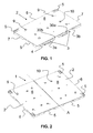
- Fig. 1
- einen Platte der zweiteiligen Palette in einer perspektivischen Ansicht;
- Fig. 2
- eine perspektivische Ansicht der zweiteiligen Palette von oben gesehen;
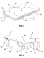
- Fig. 3
- zwei gestapelte Platten in einer perspektivischen Ansicht;
- Fig. 4
- eine Teilansicht eines Griffelementes und der Griffaufnahme;
- Fig. 5
- zwei nebeneinander angeordnete Platten der Palette von unten gesehen;
- Fig. 1
- a plate of the two-part pallet in a perspective view;
- Fig. 2
- a perspective view of the two-piece range seen from above;
- Fig. 3
- two stacked plates in a perspective view;
- Fig. 4
- a partial view of a handle member and the handle receptacle;
- Fig. 5
- two juxtaposed plates of the pallet seen from below;
In den Figuren sind für dieselben Elemente jeweils die gleichen Bezugszeichen verwendet worden und erstmalige Erklärungen betreffen alle Figuren, wenn nicht ausdrücklich anders erwähnt.In the figures, the same reference numerals have been used for the same elements and first explanations apply to all figures, unless expressly stated otherwise.
Die erfindungsgemässe zweiteilige Flachpalette 1 besteht aus zwei identischen Platten 2, die mit Kopplungsmitteln 3,30 miteinander trennbar verbunden und gehalten sind. Die
Die
In der
Die
In der
Zum Beladen der erfindungsgemässen Flachpalette 1 wird zunächst eine erste Platte 2 an der Ladestation auf die Förderanlage gelegt und beladen. Anschliessend wird eine zweite Platte 2 in die auf der Förderanlage liegende Platte 2 eingehängt und beladen. Zum Entladen einer solchen Flachpalette 1 wird umgekehrt vorgegangen. Erst wird die vordere Platte 2 entladen, dann von der zweiten Platte durch Hochkippen entkoppelt und von der Förderanlage entfernt. Danach wird die zweite Platte 2, also die zweite Hälfte der Flachpalette 1 entladen. Durch die geringere Breite der Platten 2 gegenüber einer Industriepalette wird deren Be- und Entladung wesentlich vereinfacht. Da die einzelnen Platten 2 nur die Hälfte der Flachpalette 1 darstellen, ist deren Geweicht auch nur etwa die Hälfte und damit deren Handhabung wesentlich einfacher und kräftesparend.To load the
Claims (8)
Priority Applications (1)
| Application Number | Priority Date | Filing Date | Title |
|---|---|---|---|
| PL08105748T PL2067709T3 (en) | 2007-12-06 | 2008-11-07 | Two-part flat pallet |
Applications Claiming Priority (1)
| Application Number | Priority Date | Filing Date | Title |
|---|---|---|---|
| CH18852007 | 2007-12-06 |
Publications (3)
| Publication Number | Publication Date |
|---|---|
| EP2067709A2 true EP2067709A2 (en) | 2009-06-10 |
| EP2067709A3 EP2067709A3 (en) | 2010-08-18 |
| EP2067709B1 EP2067709B1 (en) | 2012-10-31 |
Family
ID=40427976
Family Applications (1)
| Application Number | Title | Priority Date | Filing Date |
|---|---|---|---|
| EP08105748A Active EP2067709B1 (en) | 2007-12-06 | 2008-11-07 | Two-part flat pallet |
Country Status (3)
| Country | Link |
|---|---|
| US (1) | US8596207B2 (en) |
| EP (1) | EP2067709B1 (en) |
| PL (1) | PL2067709T3 (en) |
Cited By (3)
| Publication number | Priority date | Publication date | Assignee | Title |
|---|---|---|---|---|
| FR3005637A1 (en) * | 2013-05-17 | 2014-11-21 | Larbaletier | DISPLAYABLE FOLDING PALLET |
| WO2020042437A1 (en) * | 2018-08-27 | 2020-03-05 | 惠科股份有限公司 | Pallet and cargo stacking device |
| WO2020065437A1 (en) | 2018-09-26 | 2020-04-02 | Georg Utz Holding Ag | Plastic pallet with handle |
Families Citing this family (19)
| Publication number | Priority date | Publication date | Assignee | Title |
|---|---|---|---|---|
| US20100206200A1 (en) * | 2007-09-26 | 2010-08-19 | Warren Howard Tosse | Pallet system |
| CH699872A2 (en) | 2008-11-06 | 2010-05-14 | Utz Georg Holding Ag | Transport and storage containers. |
| CN101670898B (en) * | 2009-09-14 | 2011-04-13 | 刘学武 | Tray |
| CH702628A2 (en) | 2010-02-01 | 2011-08-15 | Utz Georg Holding Ag | Plastic pallet. |
| US20120125802A1 (en) * | 2010-06-14 | 2012-05-24 | Robert Treat Rayner | Material transport and storage device |
| US8464647B1 (en) * | 2011-09-20 | 2013-06-18 | Frank Chernek | Plastic pallet |
| US9010255B2 (en) * | 2012-02-02 | 2015-04-21 | Rehrig Pacific Company | Keg pallet |
| ITTO20121059A1 (en) * | 2012-12-10 | 2014-06-11 | Giordano Poultry Plast | PLATFORM FOR THE TRANSPORT OF GOODS, PARTICULARLY FLOWERS AND PLANTS |
| CN104340462A (en) | 2013-08-06 | 2015-02-11 | 康准电子科技(昆山)有限公司 | Base plate |
| US10099813B2 (en) | 2015-11-09 | 2018-10-16 | Rehrig Pacific Company | Pallet assembly |
| DE202016100228U1 (en) * | 2016-01-19 | 2016-02-12 | Montara Verpacken Mit System Gmbh | Lid for a stackable transport pallet |
| US10059361B2 (en) * | 2016-11-09 | 2018-08-28 | Spa Sled Mover, LLC | Adaptable load movement and stabilizing apparatus |
| US10589897B1 (en) * | 2017-08-11 | 2020-03-17 | Paxxal Inc. | Roto molded pallet |
| US10737832B2 (en) * | 2018-04-05 | 2020-08-11 | Rehrig Pacific Company | Half pallet |
| US11440701B2 (en) | 2018-07-25 | 2022-09-13 | Paxxal Inc. | Structural block assembly |
| US20200031522A1 (en) | 2018-07-25 | 2020-01-30 | Paxxal Inc. | Roto molded pallet |
| CN113423646B (en) * | 2019-01-05 | 2023-10-27 | 波尼拉集团有限担保公司 | Pallet module class and pallet assembly comprising same |
| US11427379B2 (en) * | 2020-02-14 | 2022-08-30 | Thomas M Fitzgerald | Modular pallet system |
| CA3123999A1 (en) * | 2021-07-06 | 2023-01-06 | Clayton P. Fearon | Improved interlocking building panel |
Citations (1)
| Publication number | Priority date | Publication date | Assignee | Title |
|---|---|---|---|---|
| WO2007124530A1 (en) | 2006-04-28 | 2007-11-08 | Bluescope Steel Limited | Water storage tank |
Family Cites Families (25)
| Publication number | Priority date | Publication date | Assignee | Title |
|---|---|---|---|---|
| US2740167A (en) * | 1952-09-05 | 1956-04-03 | John C Rowley | Interlocking parquet block |
| US3043407A (en) * | 1958-04-28 | 1962-07-10 | Marryatt Lane & Co Inc | Grids |
| US3650224A (en) * | 1969-08-25 | 1972-03-21 | William C Holden | Warehousing pallet |
| US3699901A (en) * | 1970-07-23 | 1972-10-24 | Oakland Plastics Corp | Pallet |
| US3909996A (en) * | 1974-12-12 | 1975-10-07 | Economics Lab | Modular floor mat |
| US4580680A (en) * | 1981-01-28 | 1986-04-08 | Bigelow-Sanford, Inc. | Shipping pallet and container formed therefrom |
| DK155616C (en) * | 1984-09-25 | 1989-09-04 | Eminent Plast | GRID OR MEASUREMENT ELEMENT FOR THE CREATION OF A FLOOR COVERING BY CONNECTION WITH SIMILAR ELEMENTS |
| US4917532A (en) * | 1985-11-22 | 1990-04-17 | Dr. Spiess Kunstoff-Recycling Gmbh Co. | Grid plate |
| EP0296792A3 (en) * | 1987-06-22 | 1990-01-03 | Design Count Pty. Ltd. | Pallet construction |
| US4890743A (en) * | 1988-03-11 | 1990-01-02 | Cad/Cam Tooling, Inc. | System and pallet for packaging yarn spools |
| EP0539501B1 (en) * | 1990-07-19 | 1996-10-16 | E.I. Du Pont De Nemours And Company | Interlocking pallet |
| US5263668A (en) * | 1991-10-15 | 1993-11-23 | Ast Research, Inc. | Computer pedestal |
| US5860369A (en) * | 1996-11-26 | 1999-01-19 | Plastic Pallet Production, Inc. | Interlocking modular pallet apparatus and method of construction |
| AUPO469197A0 (en) * | 1997-01-21 | 1997-02-13 | Coddington, Leigh | Modular pallet structure |
| US5950378A (en) * | 1997-12-22 | 1999-09-14 | Council; Walter S. | Composite modular floor tile |
| DE19911409A1 (en) * | 1999-03-15 | 2000-09-21 | Willibald Hergeth | Flooring, ceiling and method for creating a green area |
| US6234087B1 (en) * | 2000-01-21 | 2001-05-22 | Alltrista Corporation | Machine dispensed modular pallet |
| AUPR455601A0 (en) * | 2001-04-24 | 2001-05-24 | Strathayr Pty. Limited | Liftable turfing systems |
| US6928933B2 (en) * | 2001-07-13 | 2005-08-16 | William G. Grau | Printing press racking board and corner angle support |
| US6659019B2 (en) * | 2001-07-30 | 2003-12-09 | Rehrig Pacific Company | Folding pallet-stacking device |
| ES2241401B1 (en) * | 2002-11-15 | 2006-06-16 | Tarpack, S.L. | PALETIZED BOX. |
| US7406801B2 (en) * | 2004-02-04 | 2008-08-05 | Karl Zeng | Watertight decking |
| US20070094979A1 (en) * | 2005-10-07 | 2007-05-03 | Suncast Corporation | Plastic utility shed flooring system |
| US8316606B2 (en) * | 2006-06-08 | 2012-11-27 | Siewert Cabinet & Fixture Manufacturing, Inc. | Fastening system for panels and trim |
| US7793471B2 (en) * | 2007-11-30 | 2010-09-14 | David Tilghman Hill | Floating floor assembled from an array of interconnected subunits, each of which includes a stone, ceramic, or porcelain tile bonded to an injection molded polyolefin substrate |
-
2008
- 2008-11-07 EP EP08105748A patent/EP2067709B1/en active Active
- 2008-11-07 PL PL08105748T patent/PL2067709T3/en unknown
- 2008-12-05 US US12/328,959 patent/US8596207B2/en active Active
Patent Citations (1)
| Publication number | Priority date | Publication date | Assignee | Title |
|---|---|---|---|---|
| WO2007124530A1 (en) | 2006-04-28 | 2007-11-08 | Bluescope Steel Limited | Water storage tank |
Cited By (4)
| Publication number | Priority date | Publication date | Assignee | Title |
|---|---|---|---|---|
| FR3005637A1 (en) * | 2013-05-17 | 2014-11-21 | Larbaletier | DISPLAYABLE FOLDING PALLET |
| WO2020042437A1 (en) * | 2018-08-27 | 2020-03-05 | 惠科股份有限公司 | Pallet and cargo stacking device |
| WO2020065437A1 (en) | 2018-09-26 | 2020-04-02 | Georg Utz Holding Ag | Plastic pallet with handle |
| US11420791B2 (en) | 2018-09-26 | 2022-08-23 | Georg Utz Holding Ag | Plastic pallet with handle |
Also Published As
| Publication number | Publication date |
|---|---|
| EP2067709B1 (en) | 2012-10-31 |
| EP2067709A3 (en) | 2010-08-18 |
| PL2067709T3 (en) | 2013-03-29 |
| US8596207B2 (en) | 2013-12-03 |
| US20090145339A1 (en) | 2009-06-11 |
Similar Documents
| Publication | Publication Date | Title |
|---|---|---|
| EP2067709B1 (en) | Two-part flat pallet | |
| US20030080024A1 (en) | Reinforced double-wall knock-down bin | |
| EP2181046B1 (en) | Shuttle palette for a storage system | |
| DE202013012291U1 (en) | quarter pallet | |
| DE4341256A1 (en) | Ventilated pallet for storing goods - is lightweight plastics pallet body with reinforcement grooves and ventilation holes aligning with air holes in containers | |
| EP0584133B1 (en) | Plastic pallet | |
| EP3439985B1 (en) | Pallet container | |
| DE60215759T2 (en) | Tray system arranged on a pallet | |
| EP2636569B1 (en) | Container transport carriage for the railway transport of goods | |
| WO2013014223A1 (en) | Transport plate for bagged goods | |
| EP2930121A1 (en) | Plastic pallet for receiving flexible bulk containers | |
| DE102010037568A1 (en) | Modular transport rack | |
| EP2651796B1 (en) | Logistic system platform | |
| EP0139810A2 (en) | Transport container | |
| EP3188973B1 (en) | Arrangement of two cargo carriers on top of one another | |
| WO2005019048A1 (en) | Nestable load support | |
| EP0168060B1 (en) | Stackable pallet | |
| EP3663230A1 (en) | Transport container | |
| DE202006002645U1 (en) | Transport and storage system, for stacks of identically cut metal sheets, has a support plate in a frame with vertical supports to prevent shifting | |
| DE3907360C2 (en) | ||
| DE202017106346U1 (en) | Carrier and intermediate pallet | |
| CH705452A2 (en) | Application for a transport and storage container. | |
| CH719733A1 (en) | Plastic tray for a transport system. | |
| AT14826U1 (en) | palette | |
| DE10314111B4 (en) | Loading unit with palletizing tray |
Legal Events
| Date | Code | Title | Description |
|---|---|---|---|
| PUAI | Public reference made under article 153(3) epc to a published international application that has entered the european phase |
Free format text: ORIGINAL CODE: 0009012 |
|
| AK | Designated contracting states |
Kind code of ref document: A2 Designated state(s): AT BE BG CH CY CZ DE DK EE ES FI FR GB GR HR HU IE IS IT LI LT LU LV MC MT NL NO PL PT RO SE SI SK TR |
|
| AX | Request for extension of the european patent |
Extension state: AL BA MK RS |
|
| PUAL | Search report despatched |
Free format text: ORIGINAL CODE: 0009013 |
|
| AK | Designated contracting states |
Kind code of ref document: A3 Designated state(s): AT BE BG CH CY CZ DE DK EE ES FI FR GB GR HR HU IE IS IT LI LT LU LV MC MT NL NO PL PT RO SE SI SK TR |
|
| AX | Request for extension of the european patent |
Extension state: AL BA MK RS |
|
| 17P | Request for examination filed |
Effective date: 20110209 |
|
| AKX | Designation fees paid |
Designated state(s): CH DE FR GB LI PL |
|
| 17Q | First examination report despatched |
Effective date: 20111222 |
|
| GRAP | Despatch of communication of intention to grant a patent |
Free format text: ORIGINAL CODE: EPIDOSNIGR1 |
|
| GRAS | Grant fee paid |
Free format text: ORIGINAL CODE: EPIDOSNIGR3 |
|
| GRAA | (expected) grant |
Free format text: ORIGINAL CODE: 0009210 |
|
| AK | Designated contracting states |
Kind code of ref document: B1 Designated state(s): CH DE FR GB LI PL |
|
| REG | Reference to a national code |
Ref country code: GB Ref legal event code: FG4D Free format text: NOT ENGLISH Ref country code: CH Ref legal event code: EP |
|
| REG | Reference to a national code |
Ref country code: CH Ref legal event code: NV Representative=s name: SPIERENBURG AND PARTNER AG, PATENT- UND MARKEN, CH |
|
| REG | Reference to a national code |
Ref country code: DE Ref legal event code: R096 Ref document number: 502008008544 Country of ref document: DE Effective date: 20121227 |
|
| REG | Reference to a national code |
Ref country code: PL Ref legal event code: T3 |
|
| PLBE | No opposition filed within time limit |
Free format text: ORIGINAL CODE: 0009261 |
|
| STAA | Information on the status of an ep patent application or granted ep patent |
Free format text: STATUS: NO OPPOSITION FILED WITHIN TIME LIMIT |
|
| 26N | No opposition filed |
Effective date: 20130801 |
|
| REG | Reference to a national code |
Ref country code: DE Ref legal event code: R097 Ref document number: 502008008544 Country of ref document: DE Effective date: 20130801 |
|
| REG | Reference to a national code |
Ref country code: FR Ref legal event code: PLFP Year of fee payment: 8 |
|
| REG | Reference to a national code |
Ref country code: FR Ref legal event code: PLFP Year of fee payment: 9 |
|
| REG | Reference to a national code |
Ref country code: FR Ref legal event code: PLFP Year of fee payment: 10 |
|
| PGFP | Annual fee paid to national office [announced via postgrant information from national office to epo] |
Ref country code: PL Payment date: 20221026 Year of fee payment: 15 |
|
| PGFP | Annual fee paid to national office [announced via postgrant information from national office to epo] |
Ref country code: GB Payment date: 20231123 Year of fee payment: 16 |
|
| PGFP | Annual fee paid to national office [announced via postgrant information from national office to epo] |
Ref country code: FR Payment date: 20231122 Year of fee payment: 16 Ref country code: DE Payment date: 20231120 Year of fee payment: 16 Ref country code: CH Payment date: 20231202 Year of fee payment: 16 |
|
| PGFP | Annual fee paid to national office [announced via postgrant information from national office to epo] |
Ref country code: PL Payment date: 20231102 Year of fee payment: 16 |