EP2067667A1 - Dispositif d''atténuation des bruits se propageant entre une aile avant et une structure porteuse de carrosserie d'un vehicule - Google Patents
Dispositif d''atténuation des bruits se propageant entre une aile avant et une structure porteuse de carrosserie d'un vehicule Download PDFInfo
- Publication number
- EP2067667A1 EP2067667A1 EP08170629A EP08170629A EP2067667A1 EP 2067667 A1 EP2067667 A1 EP 2067667A1 EP 08170629 A EP08170629 A EP 08170629A EP 08170629 A EP08170629 A EP 08170629A EP 2067667 A1 EP2067667 A1 EP 2067667A1
- Authority
- EP
- European Patent Office
- Prior art keywords
- partition
- soundproofing
- shell
- vehicle
- wing
- Prior art date
- Legal status (The legal status is an assumption and is not a legal conclusion. Google has not performed a legal analysis and makes no representation as to the accuracy of the status listed.)
- Granted
Links
- 230000001902 propagating effect Effects 0.000 title claims description 6
- 238000005192 partition Methods 0.000 claims abstract description 59
- 239000013536 elastomeric material Substances 0.000 claims description 5
- 239000006261 foam material Substances 0.000 claims description 5
- 239000000463 material Substances 0.000 claims description 5
- 230000002093 peripheral effect Effects 0.000 claims description 5
- 238000004026 adhesive bonding Methods 0.000 claims description 4
- 238000007789 sealing Methods 0.000 claims description 2
- 239000006260 foam Substances 0.000 claims 1
- 239000004033 plastic Substances 0.000 description 2
- 239000004743 Polypropylene Substances 0.000 description 1
- 239000000853 adhesive Substances 0.000 description 1
- 230000001070 adhesive effect Effects 0.000 description 1
- 230000004888 barrier function Effects 0.000 description 1
- 239000011248 coating agent Substances 0.000 description 1
- 238000000576 coating method Methods 0.000 description 1
- 238000013016 damping Methods 0.000 description 1
- 230000000694 effects Effects 0.000 description 1
- 238000009413 insulation Methods 0.000 description 1
- 239000002184 metal Substances 0.000 description 1
- -1 polypropylene Polymers 0.000 description 1
- 229920001155 polypropylene Polymers 0.000 description 1
- 239000012815 thermoplastic material Substances 0.000 description 1
Images

Classifications
-
- B—PERFORMING OPERATIONS; TRANSPORTING
- B60—VEHICLES IN GENERAL
- B60R—VEHICLES, VEHICLE FITTINGS, OR VEHICLE PARTS, NOT OTHERWISE PROVIDED FOR
- B60R13/00—Elements for body-finishing, identifying, or decorating; Arrangements or adaptations for advertising purposes
- B60R13/08—Insulating elements, e.g. for sound insulation
Definitions
- the present invention relates to a noise attenuation device propagating between a vehicle wing, such as a front fender, and a vehicle body supporting structure, when the latter moves or is at a standstill.
- Such a device is known from the patent application US 2005/0230165 and comprises at least one transverse partition disposed between the rear portion of the front fender and the front foot of the vehicle body supporting structure.
- the transverse partition is provided on one of its faces with a layer of a thermally expandable material, such as a foam material, so as to close the cavity in which the partition is located to form a soundproofing barrier.
- a thermally expandable material such as a foam material
- thermally expandable soundproofing material is difficult to implement and has the additional disadvantage of not having a good behavior over time.
- the object of the present invention is to overcome the above disadvantages of known soundproofing means used in wings, especially before vehicles.
- the invention proposes a device for attenuating the noise propagating between a vehicle wing, such as a front fender, and a vehicle body supporting structure, when the latter moves or is at the stop, comprising at least one soundproofing partition disposed between an outer sidewall of the wing and the bodywork bearing structure, and which is characterized in that the soundproofing partition is provided on one of its faces with a soundproofing shell attached to the partition soundproofing covering the latter so as to define a closed and sealed internal space.
- the partition assembly and soundproofing shell is disposed transversely to the vehicle at the rear end of the side wall of the front wing to close the space between this end and the front foot of the body-carrying structure at the vehicle door entrance.
- the internal space between the shell and the soundproofing partition is filled with air.
- the soundproofing shell is fixed to the soundproofing wall by gluing.
- the wall of the soundproofing shell completely covers the soundproofing partition and extends substantially parallel to this partition.
- the soundproofing partition comprises an outer peripheral flexible seal of elastomeric material or of foam material and sealing support on the corresponding inner faces of the side wall of the wing and the bodywork bearing structure.
- the soundproofing shell is arranged in front of the vehicle.
- the invention also relates to a soundproofing partition intended to close the space between a front lateral wing of a vehicle and a bodywork bearing structure on which the wing must be fixed, and which is characterized in that it is provided on one of its faces with a soundproofing shell secured to the soundproofing partition by covering the latter so as to define a closed internal space and sealed relative to the outside.
- the internal space between the shell and the soundproofing partition is filled with air.
- the soundproofing shell is attached to the soundproofing wall by gluing.
- the wall of the soundproofing shell completely covers the soundproofing partition and extends substantially parallel to the soundproofing wall.
- the soundproofing partition comprises a flexible outer peripheral seal of elastomeric material or foam material.
- the invention relates to a vehicle comprising two front fenders and characterized in that it comprises a device as defined above for attenuating the noises propagating between each front fender of the vehicle and a vehicle body supporting structure.
- the reference numeral 1 designates a front right-hand side wing of a vehicle that may be made of a thermoplastic material or sheet metal and fixed by any appropriate means, not shown, to a body-supporting structure 2 of the vehicle, and including in particular the front foot 6 defining part of the frame of the entrance opening in the passenger compartment of the vehicle.
- the right front fender 1 comprises an outer side wall 3 extending substantially in the longitudinal direction of the vehicle and essentially having a lower edge 4 to the circular profile conjugate with that of the right front wheel of the vehicle and a rear portion 5 arranged opposite the front right foot 6 of the body 2.
- the soundproofing means of the invention for damping the noises that propagate, when stopping or when driving the vehicle, between wing 1 and foot 6 of bodywork 2.
- noises are those emitted by on the one hand the power unit located under the front hood of the vehicle and on the other hand the aerodynamic turbulence around the wheel well and the hisses of the tire of the front right wheel on different types of coating of the road.
- the soundproofing means comprise a partition 7 commonly called “wing flap” sealingly closing the space between the rear portion 5 of the wall 3 of the wing 1 and the foot 6 of the body 2 being disposed between the wall 3 and the foot 6 substantially perpendicular to the wall 3 and the foot 6.
- the partition 7 is disposed transversely to the longitudinal direction of the vehicle at the rear end of the portion 5 of the side wall 3 of the wing 1 to close the space between this end and the foot 6 at the door entrance.
- the partition 7 is provided on its outer periphery with a flexible lip seal 8 compressed by the internal faces of the rear portion 5 of the wing 1 and the front foot 6 and completely surrounding the partition 7 so as to provide a portion of sound insulation.
- the seal 8 may be made of an elastomeric material or a foam material.
- the partition 7 comprises lugs 9 ensuring its attachment, for example by screwing, to the foot 6 of the body part 2.
- the partition 7 can be fixed, before its mounting to the body part 2, to the wall 3 wing 1 by any suitable means.
- the partition 7 At its assembled position between the foot 6 and the wall 3 of the wing 1, the partition 7 extends substantially vertically along the rear portion 5 of the wall 3 and the foot 6.
- the partition 7 can be made in one. rigid plastic material, such as polypropylene.
- the soundproofing means further comprise a shell 10 integral with one of the faces of the partition 7, preferably the one located in front of the vehicle side compartment of the engine-propulsion unit thereof, so as to completely cover the partition soundproofing 7 by defining with the latter a sealed internal space relative to the outside.
- this internal space is filled with air.
- the front wall 11 of the soundproofing shell 10 extends substantially parallel to the partition 7.
- the soundproofing shell 10 is fixed to the corresponding face of the soundproofing partition 7 by a flat strip of adhesive 12 interposed between the face of the partition 7 and the peripheral edge delimiting the opening of the shell 10.
- the thickness of the front wall 11 of the shell 10 and that of the partition 7 may be identical or different.
- the soundproofing shell 10 may also be made of a rigid plastic material identical to that of the soundproofing partition 7.
- this set provides a "double glazing” effect allowing considerably reduce the noise that can spread in the passenger compartment of the vehicle and, consequently, improve the comfort of the driver and the passenger of the vehicle.
Landscapes
- Physics & Mathematics (AREA)
- Acoustics & Sound (AREA)
- Engineering & Computer Science (AREA)
- Mechanical Engineering (AREA)
- Body Structure For Vehicles (AREA)
- Vehicle Interior And Exterior Ornaments, Soundproofing, And Insulation (AREA)
- Automatic Cycles, And Cycles In General (AREA)
Abstract
Description
- La présente invention concerne un dispositif d'atténuation des bruits se propageant entre une aile de véhicule, telle qu'une aile avant, et une structure porteuse de carrosserie du véhicule, lorsque ce dernier se déplace ou est à l'arrêt.
- Un tel dispositif est connu par la demande de brevet
US 2005/0230165 et comprend au moins une cloison transversale disposée entre la partie arrière de l'aile avant et le pied avant de la structure porteuse de carrosserie du véhicule. - La cloison transversale est pourvue sur l'une de ses faces d'une couche en un matériau thermiquement expansible, tel qu'un matériau mousse, de façon à obturer la cavité dans laquelle se trouve la cloison pour constituer une barrière d'insonorisation.
- Cependant, l'utilisation d'un matériau thermiquement expansible d'insonorisation est délicate à mettre en oeuvre et a pour inconvénient supplémentaire de ne pas présenter une bonne tenue dans le temps.
- La présente invention a pour but de pallier les inconvénients ci-dessus des moyens d'insonorisation connus utilisés dans des ailes notamment avant de véhicules.
- A cet effet, l'invention propose un dispositif permettant d'atténuer les bruits se propageant entre une aile de véhicule, telle qu'une aile avant, et une structure porteuse de carrosserie du véhicule, lorsque ce dernier se déplace ou est à l'arrêt, comprenant au moins une cloison d'insonorisation disposée entre une paroi latérale externe de l'aile et la structure porteuse de carrosserie, et qui est caractérisé en ce que la cloison d'insonorisation est pourvue sur l'une de ses faces d'une coque d'insonorisation solidaire de la cloison d'insonorisation en recouvrant cette dernière de façon à définir un espace interne fermé et étanche.
- Dans le cas où l'aile est une aile avant, l'ensemble à cloison et coque d'insonorisation est disposé transversalement au véhicule à l'extrémité arrière de la paroi latérale de l'aile avant pour obturer l'espace entre cette extrémité et le pied avant de la structure porteuse de carrosserie au niveau de l'entrée de porte du véhicule.
- De préférence, l'espace interne entre coque et cloison d'insonorisation est rempli d'air.
- Avantageusement, la coque d'insonorisation est fixée à la cloison d'insonorisation par collage.
- La paroi de la coque d'insonorisation recouvre complètement la cloison d'insonorisation et s'étend de façon sensiblement parallèle à cette cloison.
- La cloison d'insonorisation comporte un joint souple périphérique externe en matériau élastomère ou en matériau mousse et en appui étanche sur les faces internes correspondantes de la paroi latérale de l'aile et de la structure porteuse de carrosserie.
- La coque d'insonorisation est disposée en avant du véhicule.
- L'invention vise également une cloison d'insonorisation destinée à obturer l'espace entre une aile latérale avant d'un véhicule et une structure porteuse de carrosserie sur laquelle l'aile doit être fixée, et qui est caractérisée en ce qu'elle est pourvue sur l'une de ses faces d'une coque d'insonorisation solidaire de la cloison d'insonorisation en recouvrant cette dernière de façon à définir un espace interne fermé et étanche relativement à l'extérieur.
- L'espace interne entre coque et cloison d'insonorisation est rempli d'air.
- La coque d'insonorisation est fixée à la cloison d'insonorisation par collage.
- La paroi de la coque d'insonorisation recouvre complètement la cloison d'insonorisation et s'étend de façon sensiblement parallèle à la cloison d'insonorisation.
- La cloison d'insonorisation comporte un joint souple périphérique externe en matériau élastomère ou en matériau mousse.
- L'invention vise enfin un véhicule comprenant deux ailes avant et caractérisé en ce qu'il comprend un dispositif tel que défini précédemment pour atténuer les bruits se propageant entre chaque aile avant du véhicule et une structure porteuse de carrosserie du véhicule.
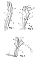
- L'invention sera mieux comprise, et d'autres buts, caractéristiques, détails et avantages de celle-ci apparaîtront plus clairement au cours de la description explicative qui va suivre faite en référence aux dessins annexés donnés uniquement à titre d'exemple illustrant un mode de réalisation de l'invention et dans lesquels :
- la
figure 1 est une vue en perspective éclatée des moyens d'insonorisation de l'invention s'appliquant à une aile avant d'un véhicule automobile ; - la
figure 2 est une vue en perspective partielle d'une partie de carrosserie de véhicule à laquelle sont fixés les moyens d'insonorisation de lafigure 1 ; - la
figure 3 est une vue en perspective suivant la flèche III de lafigure 2 ; - la
figure 4 est une vue en perspective d'une aile latérale avant fixée à une partie de carrosserie de véhicule et entre lesquelles sont montés les moyens d'insonorisation de l'invention ; et - la
figure 5 est une vue agrandie de la partie cerclée en V de lafigure 3 . - En se reportant aux figures, la référence 1 désigne une aile latérale avant droite d'un véhicule pouvant être réalisée en une matière thermoplastique ou en tôle et fixée par tout moyen approprié, non représenté, à une structure porteuse de carrosserie 2 du véhicule, et comprenant notamment le pied avant 6 délimitant en partie l'encadrement de l'ouverture d'entrée dans l'habitacle du véhicule.
- L'aile avant droite 1 comprend une paroi latérale externe 3 s'étendant sensiblement en direction longitudinale de véhicule et présentant essentiellement un bord inférieur 4 au profil circulaire conjugué de celui de la roue avant droite du véhicule et une partie arrière 5 disposée en regard du pied avant droit 6 de la carrosserie 2.
- Dans l'espace défini entre la partie arrière 5 de la paroi 3 de l'aile avant 1 et le pied avant 6 de la carrosserie 2 sont montés les moyens d'insonorisation de l'invention permettant d'amortir les bruits qui se propagent, à l'arrêt ou lors du roulage du véhicule, entre l'aile 1 et le pied 6 de carrosserie 2.
- Ces bruits sont ceux émis par d'une part le groupe moto-propulseur implanté sous le capot avant du véhicule et d'autre part les turbulences aérodynamiques autour du passage de roue et les chuintements du pneumatique de la roue avant droite sur différents types de revêtement de la route.
- Les moyens d'insonorisation comprennent une cloison 7 appelée communément "bâtant d'aile" obturant de façon étanche l'espace entre la partie arrière 5 de la paroi 3 de l'aile 1 et le pied 6 de la carrosserie 2 en étant disposée entre la paroi 3 et le pied 6 sensiblement perpendiculairement à la paroi 3 et au pied 6. Ainsi, la cloison 7 est disposée transversalement à la direction longitudinale du véhicule à l'extrémité arrière de la partie 5 de la paroi latérale 3 de l'aile 1 pour obturer l'espace entre cette extrémité et le pied 6 au niveau de l'entrée de porte. La cloison 7 est pourvue sur sa périphérie externe d'un joint souple à lèvre 8 comprimé par les faces internes de la partie arrière 5 de l'aile 1 et du pied avant 6 et entourant complètement la cloison 7 de façon à assurer une partie de l'isolation acoustique. Le joint 8 peut être réalisé en un matériau élastomère ou en un matériau mousse.
- La cloison 7 comporte des pattes 9 assurant sa fixation, par exemple par vissage, au pied 6 de la partie de carrosserie 2. En outre, la cloison 7 peut être fixée, avant son montage à la partie de carrosserie 2, à la paroi 3 de l'aile 1 par tout moyen approprié. A sa position assemblée entre le pied 6 et la paroi 3 de l'aile 1, la cloison 7 s'étend sensiblement verticalement le long de la partie arrière 5 de la paroi 3 et du pied 6. La cloison 7 peut être réalisée en une matière plastique rigide, telle que du polypropylène.
- Les moyens d'insonorisation comprennent en outre une coque 10 solidaire de l'une des faces de la cloison 7, de préférence celle située en avant du véhicule côté compartiment du groupe moto-propulseur de celui-ci, de manière à recouvrir complètement la cloison d'insonorisation 7 en définissant avec cette dernière un espace interne fermé étanche relativement à l'extérieur. De préférence, cet espace interne est rempli d'air.
- La paroi frontale 11 de la coque d'insonorisation 10 s'étend de façon sensiblement parallèle à la cloison 7.
- La coque d'insonorisation 10 est fixée à la face correspondante de la cloison d'insonorisation 7 par une bande plane de colle 12 interposée entre la face de la cloison 7 et le bord périphérique délimitant l'ouverture de la coque 10.
- L'épaisseur de la paroi frontale 11 de la coque 10 et celle de la cloison 7 peuvent être identiques ou différentes.
- La coque d'insonorisation 10 peut être également réalisée en une matière plastique rigide identique à celle de la cloison d'insonorisation 7.
- En intégrant une coque à une cloison pour emprisonner de l'air entre elles, on procure à cet ensemble un effet de « double vitrage » permettant de réduire considérablement les bruits pouvant se propager dans l'habitacle du véhicule et, par conséquent, d'améliorer le confort au conducteur et au passager du véhicule.
Claims (13)
- Dispositif permettant d'atténuer les bruits se propageant entre une aile de véhicule, telle qu'une aile avant, et une structure porteuse de carrosserie (2) du véhicule, lorsque ce dernier se déplace ou est à l'arrêt, comprenant au moins une cloison d'insonorisation (7) disposée entre une paroi latérale externe (3) de l'aile et la structure porteuse de carrosserie (2), caractérisé en ce que la cloison d'insonorisation (7) est pourvue sur l'une de ses faces d'une coque d'insonorisation (10) solidaire de la cloison d'insonorisation (7) en recouvrant cette dernière de façon à définir un espace interne fermé et étanche.
- Dispositif selon la revendication 1, caractérisé en ce que, dans le cas où l'aile (1) est une aile avant, l'ensemble à cloison (7) et coque (10) d'insonorisation est disposé transversalement au véhicule à l'extrémité arrière de la paroi latérale (3) de l'aile avant (1) pour obturer l'espace entre cette extrémité et le pied avant (6) de la structure porteuse de carrosserie (2) au niveau de l'entrée de porte.
- Dispositif selon la revendication 1 ou 2, caractérisé en ce que l'espace interne entre coque (10) et cloison (7) d'insonorisation est rempli d'air.
- Dispositif selon l'une des revendications 1 ou 2, caractérisé en ce que la coque d'insonorisation (10) est fixée à la cloison d'insonorisation (7) par collage.
- Dispositif selon l'une des revendications précédentes, caractérisé en ce que la paroi (11) de la coque d'insonorisation (10) recouvre complètement la cloison d'insonorisation (7) et s'étend de façon sensiblement parallèle à la cloison d'insonorisation (7).
- Dispositif selon l'une des revendications précédentes, caractérisé en ce que la cloison d'insonorisation (7) comporte un joint souple périphérique (8) en matériau élastomère ou en matériau mousse et en appui étanche sur les faces internes correspondantes de la paroi latérale (3) de l'aile (1) et de la structure porteuse de carrosserie (2).
- Dispositif selon l'une des revendications 2 à 6, caractérisé en ce que la coque d'insonorisation (10) est disposée en avant du véhicule.
- Cloison d'insonorisation destinée à obturer l'espace entre une aile latérale avant (1) d'un véhicule et une structure porteuse de carrosserie (2) sur laquelle l'aile (1) doit être fixée, caractérisée en ce qu'elle est pourvue sur l'une de ses faces d'une coque d'insonorisation (10) solidaire de la cloison d'insonorisation (7) en recouvrant cette dernière de façon à définir un espace interne fermé et étanche.
- Cloison selon la revendication 8, caractérisée en ce que l'espace interne entre coque (10) et cloison (7) d'insonorisation est rempli d'air.
- Cloison selon la revendication 8 ou 9, caractérisée en ce que la coque d'insonorisation (10) est fixée à la cloison d'insonorisation (7) par collage.
- Cloison selon l'une des revendications 8 à 10, caractérisée en ce que la paroi (11) de la coque d'insonorisation (10) recouvre complètement la cloison d'insonorisation (7) et s'étend de façon sensiblement parallèle à la cloison d'insonorisation (7).
- Cloison selon l'une des revendications 8 à 11, caractérisée en ce que la cloison d'insonorisation (7) comporte un joint souple périphérique (8) en matériau élastomère ou en matériau mousse.
- Véhicule comprenant deux ailes avant (1), caractérisé en ce qu'il comprend un dispositif permettant d'atténuer les bruits se propageant entre chaque aile avant du véhicule et une structure porteuse de carrosserie (2) du véhicule selon l'une quelconque des revendications 1 à 7.
Applications Claiming Priority (1)
| Application Number | Priority Date | Filing Date | Title |
|---|---|---|---|
| FR0759661A FR2924656B1 (fr) | 2007-12-07 | 2007-12-07 | Dispositif d'attenuation des bruits se propageant entre une aile avant et une structure porteuse de carrosserie d'un vehicule |
Publications (2)
| Publication Number | Publication Date |
|---|---|
| EP2067667A1 true EP2067667A1 (fr) | 2009-06-10 |
| EP2067667B1 EP2067667B1 (fr) | 2010-04-28 |
Family
ID=39639498
Family Applications (1)
| Application Number | Title | Priority Date | Filing Date |
|---|---|---|---|
| EP08170629A Not-in-force EP2067667B1 (fr) | 2007-12-07 | 2008-12-03 | Dispositif d''atténuation des bruits se propageant entre une aile avant et une structure porteuse de carrosserie d'un vehicule |
Country Status (4)
| Country | Link |
|---|---|
| EP (1) | EP2067667B1 (fr) |
| AT (1) | ATE465910T1 (fr) |
| DE (1) | DE602008001103D1 (fr) |
| FR (1) | FR2924656B1 (fr) |
Cited By (3)
| Publication number | Priority date | Publication date | Assignee | Title |
|---|---|---|---|---|
| FR2970217A1 (fr) * | 2011-01-10 | 2012-07-13 | Peugeot Citroen Automobiles Sa | Dispositif d'obturation d'un espace separant une aile de vehicule et une structure porteuse de carrosserie. |
| CN107538386A (zh) * | 2016-06-23 | 2018-01-05 | 上海安莱德汽车零部件有限公司 | 一种车身前翼子板安装夹具 |
| FR3101055A1 (fr) * | 2019-09-24 | 2021-03-26 | Psa Automobiles Sa | Pièce d’étanchéité d’aile de carrosserie de véhicule automobile |
Citations (4)
| Publication number | Priority date | Publication date | Assignee | Title |
|---|---|---|---|---|
| JP2004026060A (ja) * | 2002-06-27 | 2004-01-29 | Suzuki Motor Corp | 柔軟材の取付構造 |
| US20050230165A1 (en) | 2005-05-25 | 2005-10-20 | L&L Products, Inc. | Baffle for an automotive vehicle and method of use therefor |
| JP2006168464A (ja) * | 2004-12-14 | 2006-06-29 | Daiwa Kasei Ind Co Ltd | フェンダーサイドプロテクタ |
| JP2006219013A (ja) * | 2005-02-10 | 2006-08-24 | Daiwa Kasei Ind Co Ltd | フェンダーサイドプロテクタ |
-
2007
- 2007-12-07 FR FR0759661A patent/FR2924656B1/fr not_active Expired - Fee Related
-
2008
- 2008-12-03 EP EP08170629A patent/EP2067667B1/fr not_active Not-in-force
- 2008-12-03 AT AT08170629T patent/ATE465910T1/de not_active IP Right Cessation
- 2008-12-03 DE DE602008001103T patent/DE602008001103D1/de active Active
Patent Citations (4)
| Publication number | Priority date | Publication date | Assignee | Title |
|---|---|---|---|---|
| JP2004026060A (ja) * | 2002-06-27 | 2004-01-29 | Suzuki Motor Corp | 柔軟材の取付構造 |
| JP2006168464A (ja) * | 2004-12-14 | 2006-06-29 | Daiwa Kasei Ind Co Ltd | フェンダーサイドプロテクタ |
| JP2006219013A (ja) * | 2005-02-10 | 2006-08-24 | Daiwa Kasei Ind Co Ltd | フェンダーサイドプロテクタ |
| US20050230165A1 (en) | 2005-05-25 | 2005-10-20 | L&L Products, Inc. | Baffle for an automotive vehicle and method of use therefor |
Cited By (4)
| Publication number | Priority date | Publication date | Assignee | Title |
|---|---|---|---|---|
| FR2970217A1 (fr) * | 2011-01-10 | 2012-07-13 | Peugeot Citroen Automobiles Sa | Dispositif d'obturation d'un espace separant une aile de vehicule et une structure porteuse de carrosserie. |
| CN107538386A (zh) * | 2016-06-23 | 2018-01-05 | 上海安莱德汽车零部件有限公司 | 一种车身前翼子板安装夹具 |
| FR3101055A1 (fr) * | 2019-09-24 | 2021-03-26 | Psa Automobiles Sa | Pièce d’étanchéité d’aile de carrosserie de véhicule automobile |
| WO2021058885A1 (fr) * | 2019-09-24 | 2021-04-01 | Psa Automobiles Sa | Pièce d'étanchéité d'aile de carrosserie de véhicule automobile |
Also Published As
| Publication number | Publication date |
|---|---|
| DE602008001103D1 (de) | 2010-06-10 |
| FR2924656A1 (fr) | 2009-06-12 |
| ATE465910T1 (de) | 2010-05-15 |
| EP2067667B1 (fr) | 2010-04-28 |
| FR2924656B1 (fr) | 2009-11-20 |
Similar Documents
| Publication | Publication Date | Title |
|---|---|---|
| EP2560839B1 (fr) | Panneau de protection destine a etre fixe sur une partie de la carrosserie d'un vehicule automobile et vehicule equipe d'un tel panneau. | |
| FR2482020A1 (fr) | Structure de glace pour carrosserie de vehicule | |
| EP2067667B1 (fr) | Dispositif d''atténuation des bruits se propageant entre une aile avant et une structure porteuse de carrosserie d'un vehicule | |
| FR2968631A1 (fr) | Sous-ensemble, notamment de vehicule, a peau externe et structure interne fixees par cordon de colle | |
| WO2018162146A1 (fr) | Agencement de maintien d'un bac de coffre a l'avant d'une structure de caise d'un vehicule automobile | |
| EP1054801B1 (fr) | Agencement de la partie inferieure de l'habitacle d'un vehicule automobile | |
| EP1138538A1 (fr) | Nouveau joint d'étanchéité pour ouvrant de véhicule automobile | |
| FR2985225A1 (fr) | Pavillon vitre de vehicule, equipe d'un panneau mobile coulissant, et vehicule correspondant | |
| EP2560833B1 (fr) | Bandeau de protection et partie de la carrosserie d'un véhicule equipée d'un tel bandeau. | |
| EP1298036B1 (fr) | Aile de véhicule automobile, telle qu'une aile avant | |
| EP1818197B1 (fr) | Extracteur d'air pour véhicule automobile | |
| FR2961779A1 (fr) | Dispositif permettant de faciliter la fermeture d'une porte d'un vehicule automobile. | |
| EP2085623B1 (fr) | Procédé de montage d'un becquet sur un véhicule automobile et agencement de montage obtenu | |
| EP0940294B1 (fr) | Dispositif d'étanchéité pour rétroviseur extérieur, en particulier de véhicule automobile | |
| FR2970217A1 (fr) | Dispositif d'obturation d'un espace separant une aile de vehicule et une structure porteuse de carrosserie. | |
| EP3307576A1 (fr) | Ensemble d'une caisse en blanc de véhicule automobile et d'un hayon comportant un vérin en zone sèche | |
| FR2981302A1 (fr) | Ouvrant de vehicule automobile comprenant un element de renfort | |
| EP3752412B1 (fr) | Véhicule automobile comprenant un dispositif aérodynamique latéral | |
| FR2980426A1 (fr) | Panneau de protection destine a etre fixe sur une partie de la carrosserie d'un vehicule automobile et vehicule equipe d'un tel panneau | |
| FR2494758A1 (fr) | Fixation de glaces, notamment de pare-brise pour vehicules automobiles | |
| WO2011018570A2 (fr) | Partie avant de vehicule automobile. | |
| FR2959169A1 (fr) | Porte laterale de vehicule automobile equipee d'un bandeau de protection s'etendant dans la zone de fixation de la commande d'ouverture exterieure de la porte et vehicule ainsi equipe. | |
| WO2015150657A1 (fr) | Vehicule automobile comportant un conduit de sortie d'air de turbocompresseur en partie souple | |
| EP1932703B1 (fr) | Dispositif d'étanchéité pour l'encadrement d'une ouverture pouvant être fermée par un ouvrant d'un véhicule | |
| FR3163610A1 (fr) | Ouvrant de vehicule comportant une protection a isolation acoustique amelioree |
Legal Events
| Date | Code | Title | Description |
|---|---|---|---|
| PUAI | Public reference made under article 153(3) epc to a published international application that has entered the european phase |
Free format text: ORIGINAL CODE: 0009012 |
|
| AK | Designated contracting states |
Kind code of ref document: A1 Designated state(s): AT BE BG CH CY CZ DE DK EE ES FI FR GB GR HR HU IE IS IT LI LT LU LV MC MT NL NO PL PT RO SE SI SK TR |
|
| AX | Request for extension of the european patent |
Extension state: AL BA MK RS |
|
| 17P | Request for examination filed |
Effective date: 20090930 |
|
| GRAP | Despatch of communication of intention to grant a patent |
Free format text: ORIGINAL CODE: EPIDOSNIGR1 |
|
| GRAS | Grant fee paid |
Free format text: ORIGINAL CODE: EPIDOSNIGR3 |
|
| AKX | Designation fees paid |
Designated state(s): AT BE BG CH CY CZ DE DK EE ES FI FR GB GR HR HU IE IS IT LI LT LU LV MC MT NL NO PL PT RO SE SI SK TR |
|
| GRAA | (expected) grant |
Free format text: ORIGINAL CODE: 0009210 |
|
| AK | Designated contracting states |
Kind code of ref document: B1 Designated state(s): AT BE BG CH CY CZ DE DK EE ES FI FR GB GR HR HU IE IS IT LI LT LU LV MC MT NL NO PL PT RO SE SI SK TR |
|
| REG | Reference to a national code |
Ref country code: GB Ref legal event code: FG4D Free format text: NOT ENGLISH |
|
| REG | Reference to a national code |
Ref country code: CH Ref legal event code: EP |
|
| REG | Reference to a national code |
Ref country code: IE Ref legal event code: FG4D Free format text: LANGUAGE OF EP DOCUMENT: FRENCH |
|
| REF | Corresponds to: |
Ref document number: 602008001103 Country of ref document: DE Date of ref document: 20100610 Kind code of ref document: P |
|
| REG | Reference to a national code |
Ref country code: GB Ref legal event code: 746 Effective date: 20100607 |
|
| REG | Reference to a national code |
Ref country code: NL Ref legal event code: VDEP Effective date: 20100428 |
|
| LTIE | Lt: invalidation of european patent or patent extension |
Effective date: 20100428 |
|
| PG25 | Lapsed in a contracting state [announced via postgrant information from national office to epo] |
Ref country code: NL Free format text: LAPSE BECAUSE OF FAILURE TO SUBMIT A TRANSLATION OF THE DESCRIPTION OR TO PAY THE FEE WITHIN THE PRESCRIBED TIME-LIMIT Effective date: 20100428 Ref country code: LT Free format text: LAPSE BECAUSE OF FAILURE TO SUBMIT A TRANSLATION OF THE DESCRIPTION OR TO PAY THE FEE WITHIN THE PRESCRIBED TIME-LIMIT Effective date: 20100428 Ref country code: NO Free format text: LAPSE BECAUSE OF FAILURE TO SUBMIT A TRANSLATION OF THE DESCRIPTION OR TO PAY THE FEE WITHIN THE PRESCRIBED TIME-LIMIT Effective date: 20100728 Ref country code: SE Free format text: LAPSE BECAUSE OF FAILURE TO SUBMIT A TRANSLATION OF THE DESCRIPTION OR TO PAY THE FEE WITHIN THE PRESCRIBED TIME-LIMIT Effective date: 20100428 Ref country code: ES Free format text: LAPSE BECAUSE OF FAILURE TO SUBMIT A TRANSLATION OF THE DESCRIPTION OR TO PAY THE FEE WITHIN THE PRESCRIBED TIME-LIMIT Effective date: 20100808 |
|
| REG | Reference to a national code |
Ref country code: IE Ref legal event code: FD4D |
|
| PG25 | Lapsed in a contracting state [announced via postgrant information from national office to epo] |
Ref country code: SI Free format text: LAPSE BECAUSE OF FAILURE TO SUBMIT A TRANSLATION OF THE DESCRIPTION OR TO PAY THE FEE WITHIN THE PRESCRIBED TIME-LIMIT Effective date: 20100428 Ref country code: AT Free format text: LAPSE BECAUSE OF FAILURE TO SUBMIT A TRANSLATION OF THE DESCRIPTION OR TO PAY THE FEE WITHIN THE PRESCRIBED TIME-LIMIT Effective date: 20100428 Ref country code: FI Free format text: LAPSE BECAUSE OF FAILURE TO SUBMIT A TRANSLATION OF THE DESCRIPTION OR TO PAY THE FEE WITHIN THE PRESCRIBED TIME-LIMIT Effective date: 20100428 Ref country code: HR Free format text: LAPSE BECAUSE OF FAILURE TO SUBMIT A TRANSLATION OF THE DESCRIPTION OR TO PAY THE FEE WITHIN THE PRESCRIBED TIME-LIMIT Effective date: 20100428 Ref country code: IS Free format text: LAPSE BECAUSE OF FAILURE TO SUBMIT A TRANSLATION OF THE DESCRIPTION OR TO PAY THE FEE WITHIN THE PRESCRIBED TIME-LIMIT Effective date: 20100828 Ref country code: LV Free format text: LAPSE BECAUSE OF FAILURE TO SUBMIT A TRANSLATION OF THE DESCRIPTION OR TO PAY THE FEE WITHIN THE PRESCRIBED TIME-LIMIT Effective date: 20100428 |
|
| PG25 | Lapsed in a contracting state [announced via postgrant information from national office to epo] |
Ref country code: CY Free format text: LAPSE BECAUSE OF FAILURE TO SUBMIT A TRANSLATION OF THE DESCRIPTION OR TO PAY THE FEE WITHIN THE PRESCRIBED TIME-LIMIT Effective date: 20100609 Ref country code: PL Free format text: LAPSE BECAUSE OF FAILURE TO SUBMIT A TRANSLATION OF THE DESCRIPTION OR TO PAY THE FEE WITHIN THE PRESCRIBED TIME-LIMIT Effective date: 20100428 |
|
| PG25 | Lapsed in a contracting state [announced via postgrant information from national office to epo] |
Ref country code: IE Free format text: LAPSE BECAUSE OF FAILURE TO SUBMIT A TRANSLATION OF THE DESCRIPTION OR TO PAY THE FEE WITHIN THE PRESCRIBED TIME-LIMIT Effective date: 20100428 Ref country code: EE Free format text: LAPSE BECAUSE OF FAILURE TO SUBMIT A TRANSLATION OF THE DESCRIPTION OR TO PAY THE FEE WITHIN THE PRESCRIBED TIME-LIMIT Effective date: 20100428 Ref country code: DK Free format text: LAPSE BECAUSE OF FAILURE TO SUBMIT A TRANSLATION OF THE DESCRIPTION OR TO PAY THE FEE WITHIN THE PRESCRIBED TIME-LIMIT Effective date: 20100428 |
|
| PG25 | Lapsed in a contracting state [announced via postgrant information from national office to epo] |
Ref country code: CZ Free format text: LAPSE BECAUSE OF FAILURE TO SUBMIT A TRANSLATION OF THE DESCRIPTION OR TO PAY THE FEE WITHIN THE PRESCRIBED TIME-LIMIT Effective date: 20100428 Ref country code: RO Free format text: LAPSE BECAUSE OF FAILURE TO SUBMIT A TRANSLATION OF THE DESCRIPTION OR TO PAY THE FEE WITHIN THE PRESCRIBED TIME-LIMIT Effective date: 20100428 Ref country code: SK Free format text: LAPSE BECAUSE OF FAILURE TO SUBMIT A TRANSLATION OF THE DESCRIPTION OR TO PAY THE FEE WITHIN THE PRESCRIBED TIME-LIMIT Effective date: 20100428 |
|
| PLBE | No opposition filed within time limit |
Free format text: ORIGINAL CODE: 0009261 |
|
| STAA | Information on the status of an ep patent application or granted ep patent |
Free format text: STATUS: NO OPPOSITION FILED WITHIN TIME LIMIT |
|
| PG25 | Lapsed in a contracting state [announced via postgrant information from national office to epo] |
Ref country code: IT Free format text: LAPSE BECAUSE OF FAILURE TO SUBMIT A TRANSLATION OF THE DESCRIPTION OR TO PAY THE FEE WITHIN THE PRESCRIBED TIME-LIMIT Effective date: 20100428 |
|
| 26N | No opposition filed |
Effective date: 20110131 |
|
| PG25 | Lapsed in a contracting state [announced via postgrant information from national office to epo] |
Ref country code: GR Free format text: LAPSE BECAUSE OF FAILURE TO SUBMIT A TRANSLATION OF THE DESCRIPTION OR TO PAY THE FEE WITHIN THE PRESCRIBED TIME-LIMIT Effective date: 20100729 |
|
| BERE | Be: lapsed |
Owner name: PEUGEOT CITROEN AUTOMOBILES S.A. Effective date: 20101231 |
|
| PG25 | Lapsed in a contracting state [announced via postgrant information from national office to epo] |
Ref country code: MC Free format text: LAPSE BECAUSE OF NON-PAYMENT OF DUE FEES Effective date: 20101231 |
|
| PG25 | Lapsed in a contracting state [announced via postgrant information from national office to epo] |
Ref country code: BE Free format text: LAPSE BECAUSE OF NON-PAYMENT OF DUE FEES Effective date: 20101231 |
|
| PG25 | Lapsed in a contracting state [announced via postgrant information from national office to epo] |
Ref country code: MT Free format text: LAPSE BECAUSE OF FAILURE TO SUBMIT A TRANSLATION OF THE DESCRIPTION OR TO PAY THE FEE WITHIN THE PRESCRIBED TIME-LIMIT Effective date: 20100428 |
|
| PG25 | Lapsed in a contracting state [announced via postgrant information from national office to epo] |
Ref country code: LU Free format text: LAPSE BECAUSE OF NON-PAYMENT OF DUE FEES Effective date: 20101203 Ref country code: HU Free format text: LAPSE BECAUSE OF FAILURE TO SUBMIT A TRANSLATION OF THE DESCRIPTION OR TO PAY THE FEE WITHIN THE PRESCRIBED TIME-LIMIT Effective date: 20101029 Ref country code: BG Free format text: LAPSE BECAUSE OF FAILURE TO SUBMIT A TRANSLATION OF THE DESCRIPTION OR TO PAY THE FEE WITHIN THE PRESCRIBED TIME-LIMIT Effective date: 20100428 |
|
| PG25 | Lapsed in a contracting state [announced via postgrant information from national office to epo] |
Ref country code: TR Free format text: LAPSE BECAUSE OF FAILURE TO SUBMIT A TRANSLATION OF THE DESCRIPTION OR TO PAY THE FEE WITHIN THE PRESCRIBED TIME-LIMIT Effective date: 20100428 |
|
| PGFP | Annual fee paid to national office [announced via postgrant information from national office to epo] |
Ref country code: DE Payment date: 20121122 Year of fee payment: 5 |
|
| PGFP | Annual fee paid to national office [announced via postgrant information from national office to epo] |
Ref country code: GB Payment date: 20121122 Year of fee payment: 5 |
|
| PGFP | Annual fee paid to national office [announced via postgrant information from national office to epo] |
Ref country code: FR Payment date: 20130130 Year of fee payment: 5 |
|
| PG25 | Lapsed in a contracting state [announced via postgrant information from national office to epo] |
Ref country code: PT Free format text: LAPSE BECAUSE OF NON-PAYMENT OF DUE FEES Effective date: 20100428 |
|
| REG | Reference to a national code |
Ref country code: CH Ref legal event code: PL |
|
| PG25 | Lapsed in a contracting state [announced via postgrant information from national office to epo] |
Ref country code: BG Free format text: LAPSE BECAUSE OF FAILURE TO SUBMIT A TRANSLATION OF THE DESCRIPTION OR TO PAY THE FEE WITHIN THE PRESCRIBED TIME-LIMIT Effective date: 20100728 |
|
| PG25 | Lapsed in a contracting state [announced via postgrant information from national office to epo] |
Ref country code: CH Free format text: LAPSE BECAUSE OF NON-PAYMENT OF DUE FEES Effective date: 20121231 Ref country code: LI Free format text: LAPSE BECAUSE OF NON-PAYMENT OF DUE FEES Effective date: 20121231 |
|
| REG | Reference to a national code |
Ref country code: DE Ref legal event code: R119 Ref document number: 602008001103 Country of ref document: DE |
|
| GBPC | Gb: european patent ceased through non-payment of renewal fee |
Effective date: 20131203 |
|
| REG | Reference to a national code |
Ref country code: DE Ref legal event code: R119 Ref document number: 602008001103 Country of ref document: DE Effective date: 20140701 |
|
| REG | Reference to a national code |
Ref country code: FR Ref legal event code: ST Effective date: 20140829 |
|
| PG25 | Lapsed in a contracting state [announced via postgrant information from national office to epo] |
Ref country code: DE Free format text: LAPSE BECAUSE OF NON-PAYMENT OF DUE FEES Effective date: 20140701 |
|
| PG25 | Lapsed in a contracting state [announced via postgrant information from national office to epo] |
Ref country code: GB Free format text: LAPSE BECAUSE OF NON-PAYMENT OF DUE FEES Effective date: 20131203 Ref country code: FR Free format text: LAPSE BECAUSE OF NON-PAYMENT OF DUE FEES Effective date: 20131231 |