EP2067659B1 - Lever switch device - Google Patents
Lever switch device Download PDFInfo
- Publication number
- EP2067659B1 EP2067659B1 EP08170534.5A EP08170534A EP2067659B1 EP 2067659 B1 EP2067659 B1 EP 2067659B1 EP 08170534 A EP08170534 A EP 08170534A EP 2067659 B1 EP2067659 B1 EP 2067659B1
- Authority
- EP
- European Patent Office
- Prior art keywords
- lever
- switch device
- switch
- main body
- bracket
- Prior art date
- Legal status (The legal status is an assumption and is not a legal conclusion. Google has not performed a legal analysis and makes no representation as to the accuracy of the status listed.)
- Active
Links
- 239000000758 substrate Substances 0.000 claims description 18
- 230000000694 effects Effects 0.000 description 3
- 238000010276 construction Methods 0.000 description 1
- 230000004048 modification Effects 0.000 description 1
- 238000012986 modification Methods 0.000 description 1
- 230000002093 peripheral effect Effects 0.000 description 1
Images


Classifications
-
- B—PERFORMING OPERATIONS; TRANSPORTING
- B60—VEHICLES IN GENERAL
- B60Q—ARRANGEMENT OF SIGNALLING OR LIGHTING DEVICES, THE MOUNTING OR SUPPORTING THEREOF OR CIRCUITS THEREFOR, FOR VEHICLES IN GENERAL
- B60Q1/00—Arrangement of optical signalling or lighting devices, the mounting or supporting thereof or circuits therefor
- B60Q1/02—Arrangement of optical signalling or lighting devices, the mounting or supporting thereof or circuits therefor the devices being primarily intended to illuminate the way ahead or to illuminate other areas of way or environments
- B60Q1/04—Arrangement of optical signalling or lighting devices, the mounting or supporting thereof or circuits therefor the devices being primarily intended to illuminate the way ahead or to illuminate other areas of way or environments the devices being headlights
- B60Q1/14—Arrangement of optical signalling or lighting devices, the mounting or supporting thereof or circuits therefor the devices being primarily intended to illuminate the way ahead or to illuminate other areas of way or environments the devices being headlights having dimming means
- B60Q1/1446—Arrangement of optical signalling or lighting devices, the mounting or supporting thereof or circuits therefor the devices being primarily intended to illuminate the way ahead or to illuminate other areas of way or environments the devices being headlights having dimming means controlled by mechanically actuated switches
- B60Q1/1453—Hand actuated switches
- B60Q1/1461—Multifunction switches for dimming headlights and controlling additional devices, e.g. for controlling direction indicating lights
- B60Q1/1469—Multifunction switches for dimming headlights and controlling additional devices, e.g. for controlling direction indicating lights controlled by or attached to a single lever, e.g. steering column stalk switches
- B60Q1/1476—Multifunction switches for dimming headlights and controlling additional devices, e.g. for controlling direction indicating lights controlled by or attached to a single lever, e.g. steering column stalk switches comprising switch controlling means located near the free end of the lever, e.g. press buttons, rotatable rings
Definitions
- the present invention relates to a lever switch device and in particular, but not exclusively, to a lever switch device applied to a vehicle such as an automobile, etc.
- An example of a lever switch device applied to a vehicle such as an automobile, etc. is configured to provide two operating knobs at tip portions of a lever which operates a turn signal switch.
- the lever is rotatably provided on a body and, at the same time, two remote shafts operated by the two operating knobs are incorporated in the lever in a rotatable state.
- switches corresponding to the two operating knobs provided on the body are configured to carry out a switching operation by a rotation of the tip portions of the remote shafts according to a rotational operation of the operating knobs and as is known from JP-A 11-250772 .
- lever switch device since two rotationally operable operating knobs are provided in the lever, it is possible to simplify a structure in the lever and thereby to realize a lever switch for a vehicle having an downsized operating lever.
- EP 0 577 499 A1 discloses a lever switch device, comprising: a rotatably supported lever main body; a first remote shaft rotatably incorporated in the lever main body, and having a first operating knob at one end and a first operation portion at another end for operating a switch and by a rotational operation of the first operating knob; a second remote shaft rotatably arranged in the lever main body, coaxially with the first remote shaft, and having a second operating knob at one end and a second operation portion at another end for operating a switch and by a rotational operation of the second operating knob.
- the invention seeks to provide for a lever switch device having advantages over known such devices.
- the invention seeks to provide a lever switch device in that switching accuracy of switches provided on a body side corresponding to operating knobs is not deteriorated or an operation angle of the lever is not limited even when the lever is rotationally operated.
- a lever switch device comprising:
- the first and/or second operation portions may operate the switch via an arm.
- FIG.1 is a cross sectional view showing a lever switch device in a first embodiment of the present invention.
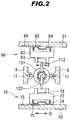
- FIG.2 is a cross sectional view along A-A line in FIG.1 including a rotation axis C of a lever main body with a bracket.
- the lever switch device shown in FIG.1 is provided at a peripheral portion of a steering column of a vehicle which is not illustrated, and a direction B in FIG.1 is a substantially forward direction of the vehicle, hence, FIG.1 is a cross sectional view of the lever switch device when viewed from an upward direction of the vehicle.
- a body 1 includes a front case 2 and a back case 3, and an outer shell of the body 1 is composed of the front case 2 and the back case 3.
- a middle case 4 and substrates 51 and 52 are provided between the front case 2 and the back case 3.
- a bracket 6 is rotataby provided around a stem portion 7 between the front case 2 and the middle case 4.
- a rotation direction of the bracket 6 is a direction about the rotation axis C of a lever unit 100 around the stem portion 7.
- a groove 8 is formed on an upper side of the middle case 4 in FIG.1 and a convex portion 9 which is slidingly movable in the groove 8 is formed in the bracket 6.
- the groove 8 is a groove in a circular arc shape concentric with the stem portion 7, even though it is not illustrated.
- a hollow portion 10 is formed on a right side of the bracket 6 in FIG.1 , and a proximal end of the lever unit 100 is inserted into the hollow portion 10.
- the lever unit 100 is rotataby provided around a stem portion 12 shown in FIG.2 Rotation directions of the lever unit 100 around the stem portion 12 are an arrow D direction (rear) and an E direction (forward) opposite thereto as shown in FIG.1 . In this case, the lever unit 100 is projecting to a right side of the body 1 in FIG.1 .
- a projecting portion 14 having a blind bore 13 is formed at the proximal end of the lever unit 100.
- a spring 15 and a moderation piece 16 are housed in the blind bore 13.
- a moderation wall 17 having three roots is formed in an inner part of the hollow portion 10 in the bracket 6. In the state of FIG.1 , the moderation piece 16 of the lever unit 100 is fitted with a middle root of the moderation wall 17 by a biasing force of the spring 15.
- the lever unit 100 is composed of a lever main body 101 having a cylindrical hollow section, a first remote shaft 111 integrally rotating with a first operating knob 110, a first operation portion 112 formed on an opposite side of the first operating knob 110 of the first remote shaft 111, a second remote shaft 121 integrally rotating with a second operating knob 120 and a second operation portion 122 formed on an opposite side of the second operating knob 120 of the second remote shaft 121.
- the lever unit 100 is a portion supported to be rotatable with respect to the body 1, and may include the above described moderation piece 16 or the like.
- the first remote shaft 111 is incorporated rotatably, the first operating knob 110 is mounted on one end of the first remote shaft 111 and the first operation portion 112 is attached to another end so as to project upward from a notch 101 a of the lever main body 101 in FIG.1 .
- the first remote shaft 111 has a hollow portion therein and the second remote shaft 121 is rotatably arranged with a coaxial structure (concentrically arranged) in the hollow portion.
- the second operating knob 120 is mounted on one end of the second remote shaft 121 and the second operation portion 122 is attached to another end so as to project downward from a notch 101b of the lever main body 101 in FIG.1 .
- the first operation portion 112 and the second operation portion 122 are arranged with a portion on the rotation axis C of the bracket (6) in FIG.1 .
- the each tip portion at least of the first operation portion 112 and the second operation portion 122 can be arranged on the rotation axis C of the bracket (6).
- a contact holder 62 is assembled in the front case 2, i.e. on a lower side of the substrate 51 attached to the body 1 side in FIG.1 , to be movable in a vertical direction (a direction orthogonal to the paper surface of FIG.1 ).
- a fitting concave portion 63 is formed on a lower part of the contact holder 62 in FIG.1 and FIG.2 , and the first operation portion 112 is fitted with the fitting concave portion 63.
- the first operation portion 112 is rotationally operated when rotationally operating the first operating knob 110, and as shown in FIG.2 , the contact holder 62 is configured to reciprocate in a direction indicated by an arrow F.
- a movable contact 64 is supported by the contact holder 62 on the substrate 51 side.
- a fixed contact 65 is provided on the substrate 51, and the movable contact 64 carries out a switching operation by contacting with and separating from the fixed contact 65 according to the movement of the contact holder 62.
- the movable contact 64 and the fixed contact 65 composes a first switch 66 provided on the body 1 side.
- the first switch 66 functions as, e.g., a light control switch for controlling turn-on/turn-off of a non-illustrated small lamp, etc.
- a contact holder 72 is assembled in the back case 3, i.e. on a upper side of the substrate 52 attached to the body 1 side in FIG.1 , to be movable in a vertical direction (a direction orthogonal to the paper surface of FIG . 1 ).
- a fitting concave portion 73 is formed on an upper part of the contact holder 72, and the second operation portion 122 is fitted with the fitting concave portion 73.
- the second operation portion 122 is rotationally operated when rotationally operating the second operating knob 120, and as shown in FIG.2 , the contact holder 72 is configured to reciprocate in a direction indicated by an arrow G.
- a movable contact 74 is supported by the contact holder 72 on the substrate 52 side.
- a fixed contact 75 is provided on the substrate 52, and the movable contact 74 carries out a switching operation by contacting with and separating from the fixed contact 75 according to the movement of the contact holder 72.
- the movable contact 74 and the fixed contact 75 composes a second switch 76 provided on the body 1 side.
- the second switch 76 functions as, e.g., a light control switch for controlling turn-on/turn-off of a non-illustrated headlamp, etc.
- the contact holder 62 is reciprocated by the first operation portion 112, thereby it is possible to carry out the switching operation of the first switch 66.
- the second operating knob 120 is rotationally operated, the second remote shaft 121 and the second operation portion 122 rotate integrally, the contact holder 72 is reciprocated by the second operation portion 122, thereby it is possible to carry out the switching operation of the second switch 76.
- a third switch for carrying out a switching operation according to the rotation of the bracket 6, fourth and fifth switches for carrying out switching operations according to the rotations of the lever unit 100 in the arrow D and E directions in FIG.1 are provided inside the body 1, even though none of them are illustrated.
- the third switch functions as, e.g., a switch for controlling a turn signal
- the fourth switch functions as, e.g., a switch for carrying out a dimmer control of a headlamp
- the fifth switch functions as, e.g., a switch for controlling passing.
- the non-illustrated fourth switch is operated and the dimmer control of the headlamp is carried out.
- the moderation piece 16 crosses over a crest on an upper side in FIG.1 from the middle root in the moderation wall 17 while compressing the spring 15, and is engaged with a root on its upper side.
- the moderation feeling is imparted to the operation of the lever main body 101 in the arrow D direction by this movement.
- the lever main body 101 when the lever main body 101 is rotationally operated in a direction indicated by the arrow E (forward), the lever main body 101 rotates in the arrow E direction around the stem portion 12 shown in FIG.2 . As a result, the non-illustrated fifth switch is operated and the passing control is carried out. At this time, the moderation piece 16 moves to a lower crest in FIG.1 from the middle root in the moderation wall 17 while compressing the spring 15, and by the resistance thereof, the moderation feeling is imparted to the rotational operation of the lever main body 101 in a forward direction. In case of this configuration, when the operation by a user is released at the moment that the moderation feeling is imparted, the lever main body 101 automatically returns as the moderation piece 16 is restored to the original root by the spring 15. On the other hand, after operating the aforementioned lever main body 101 backwards, the moderation piece 16 returns to the original root from the upper root in FIG.1 crossing over the lower crest by manually returning the lever main body 101.
- the first operation portion 112 and the second operation portion 122 are arranged on the rotation axis C of the lever main body 101 with the bracket 6 in FIG.1 . Even when the lever main body 101 with the bracket (6) is rotationally operated in this state about the rotation axis C around the stem portion 7 shown in FIG.1 , the first operation portion 112 and the second operation portion 122 remain on the rotation axis C. That is, in a particular advantageous aspect, the plane of rotation of the first and second operation portion 112, 122 can be parallel to the said rotation axis C, and the centre of rotation of each portion 112, 122 can be on the said rotation axis C.
- a tip portion of the first and second operation portion can also be provided on the said centre of rotation. Therefore, regardless of the rotational operation of the lever main body 101, positional relations between the first operation portion 112 and the fitting concave portion 63 and between the second operation portion 122 and the fitting concave portion 73 are constant, and there are effects that switching accuracy (of the first switch 66 and the second switch 76) is advantageously not reduced and the operation angle of the lever is not limited. Furthermore, since the first switch 66 and the second switch 76 are attached to the body 1 side, the wiring, etc. is facilitated, and thus, it is possible to provide a lever switch device with high reliability at low cost.
- FIG.3 is a cross sectional view showing a lever switch device in a second embodiment of the invention, which is a view corresponding to an A-A cross-section in FIG.1 including the rotation axis C of the lever main body (101) with the bracket (6).
- a first switch 86 is operated by an operation of the first operation portion 112 via an arm 80.
- the arm 80 is slidably attached to the front case 2 side by, e.g., a linear slide guide 81, and the first operation portion 112 is fitted with a fitting concave portion 83 of the linear slide guide 81.
- a movable contact 84 is attached at an end of the arm 80 on the substrate 52 side.
- a fixed contact 85 is pattern-formed on the same surface as the second switch 76, and a first switch 86 is composed of the movable contact 84 and the fixed contact 85.
- Other configurations are same as the first embodiment.
- FIG.4 is a cross sectional view showing a lever switch device in a third embodiment of the invention, which is a view corresponding to an A-A cross-section in FIG.1 including the rotation axis C of the lever main body (101) with the bracket (6).
- the first operation portion 112 is substantially U-shaped or substantially C-shaped as shown in FIG.4 , and operates a first switch 96 mounted on the substrate 52 .
- the first operation portion 112 has an arm portion 112 a in a substantially U-shape or C-shape, and as shown in FIG.4 , it is possible to transmit the rotational operation of the first operating knob 110 to a reverse side of the substrate 52.
- the first switch 96 is mounted on a reverse surface of the second switch 76 mounting surface.
- a tip portion of the operation portion 112 is fitted with a fitting concave portion 93 of a contact holder 92 in the first switch 96.
- first remote shaft 111 and the second remote shaft 121 are rotatably arranged in the lever main body 101 with a coaxial structure
- three or more the remote shafts may be arranged in the lever main body 101 with the coaxial structure.
- by the rotational operations of three or more operating knobs it is possible to drive the three or more remote shafts and operation portions each corresponding thereto, and it is also possible to operate three or more switches by three or more operating knobs.
Description
- The present invention relates to a lever switch device and in particular, but not exclusively, to a lever switch device applied to a vehicle such as an automobile, etc.
- An example of a lever switch device applied to a vehicle such as an automobile, etc. is configured to provide two operating knobs at tip portions of a lever which operates a turn signal switch. In the case of this configuration, the lever is rotatably provided on a body and, at the same time, two remote shafts operated by the two operating knobs are incorporated in the lever in a rotatable state. Then, switches corresponding to the two operating knobs provided on the body are configured to carry out a switching operation by a rotation of the tip portions of the remote shafts according to a rotational operation of the operating knobs and as is known from
JP-A 11-250772 - According to such a lever switch device, since two rotationally operable operating knobs are provided in the lever, it is possible to simplify a structure in the lever and thereby to realize a lever switch for a vehicle having an downsized operating lever.
- However, with regard to lever switch devices such as known from
JP-A 11-250772 -
EP 0 577 499 A1 discloses a lever switch device, comprising: a rotatably supported lever main body; a first remote shaft rotatably incorporated in the lever main body, and having a first operating knob at one end and a first operation portion at another end for operating a switch and by a rotational operation of the first operating knob; a second remote shaft rotatably arranged in the lever main body, coaxially with the first remote shaft, and having a second operating knob at one end and a second operation portion at another end for operating a switch and by a rotational operation of the second operating knob. The invention seeks to provide for a lever switch device having advantages over known such devices. - In particular, the invention seeks to provide a lever switch device in that switching accuracy of switches provided on a body side corresponding to operating knobs is not deteriorated or an operation angle of the lever is not limited even when the lever is rotationally operated.
- According to a feature of the present invention, there is provided a lever switch device, comprising:
- a bracket rotatably supported by a body about a rotation centre axis;
- a lever main body rotatably supported by the bracket about an axis of rotation different from the said rotation centre axis;
- a first remote shaft rotatably incorporated in the lever main body, and having a first operating knob at one end and a first operation portion at another end for operating a switch provided on the body and by a rotational operation of the first operating knob;
- a second remote shaft rotatably arranged in the lever main body, coaxially with the first remote shaft, and having a second operating knob at one end and a second operation portion at another end for operating a switch provided on the body and by a rotational operation of the second operating knob, wherein rotation centres of the first and second operation portions are provided on the said rotation centre axis of the bracket. In the lever switch device described above, the operational object may be a switch provided on the body side.
- Furthermore, in such a lever switch device, the first and/or second operation portions may operate the switch via an arm.
- According to the invention, it is possible to provide a lever switch device wherein the switching accuracy and reliability of switches provided on a body side corresponding to operating knobs does not reduce nor is an operation angle of the lever limited, even when the lever is rotationally operated.
- The present invention is described further hereinafter, by way of example only, with reference to the accompanying drawings in which:
-
FIG.1 is a cross sectional view showing a lever switch device of a first embodiment of the present invention; -
FIG.2 is a cross sectional view along A-A line inFIG.1 including a rotation axis C of a lever main body with a bracket; -
FIG.3 is a cross sectional view showing a lever switch device of a second embodiment of the invention, which is a view corresponding to an A-A cross-section ofFIG.1 including the rotation axis C of the lever main body with a bracket; and -
FIG.4 is a cross sectional view showing a lever switch device of a third preferred embodiment of the invention, which is a view corresponding to an A-A cross-section ofFIG.1 including the rotation axis C of the lever main body with a bracket. -
FIG.1 is a cross sectional view showing a lever switch device in a first embodiment of the present invention.FIG.2 is a cross sectional view along A-A line inFIG.1 including a rotation axis C of a lever main body with a bracket. The lever switch device shown inFIG.1 is provided at a peripheral portion of a steering column of a vehicle which is not illustrated, and a direction B inFIG.1 is a substantially forward direction of the vehicle, hence,FIG.1 is a cross sectional view of the lever switch device when viewed from an upward direction of the vehicle.
A body 1 includes afront case 2 and aback case 3, and an outer shell of the body 1 is composed of thefront case 2 and theback case 3. A middle case 4 andsubstrates front case 2 and theback case 3. Abracket 6 is rotataby provided around a stem portion 7 between thefront case 2 and the middle case 4. - A rotation direction of the
bracket 6 is a direction about the rotation axis C of alever unit 100 around the stem portion 7. For guiding a rotation of thebracket 6, agroove 8 is formed on an upper side of the middle case 4 inFIG.1 and aconvex portion 9 which is slidingly movable in thegroove 8 is formed in thebracket 6. Thegroove 8 is a groove in a circular arc shape concentric with the stem portion 7, even though it is not illustrated. - In addition, a
hollow portion 10 is formed on a right side of thebracket 6 inFIG.1 , and a proximal end of thelever unit 100 is inserted into thehollow portion 10. Thelever unit 100 is rotataby provided around astem portion 12 shown inFIG.2 Rotation directions of thelever unit 100 around thestem portion 12 are an arrow D direction (rear) and an E direction (forward) opposite thereto as shown inFIG.1 . In this case, thelever unit 100 is projecting to a right side of the body 1 inFIG.1 . - In addition, a projecting
portion 14 having ablind bore 13 is formed at the proximal end of thelever unit 100. Aspring 15 and amoderation piece 16 are housed in theblind bore 13. On the other hand, amoderation wall 17 having three roots is formed in an inner part of thehollow portion 10 in thebracket 6. In the state ofFIG.1 , themoderation piece 16 of thelever unit 100 is fitted with a middle root of themoderation wall 17 by a biasing force of thespring 15. - The
lever unit 100 is composed of a levermain body 101 having a cylindrical hollow section, a firstremote shaft 111 integrally rotating with afirst operating knob 110, afirst operation portion 112 formed on an opposite side of thefirst operating knob 110 of the firstremote shaft 111, a secondremote shaft 121 integrally rotating with asecond operating knob 120 and asecond operation portion 122 formed on an opposite side of thesecond operating knob 120 of the secondremote shaft 121. Thelever unit 100 is a portion supported to be rotatable with respect to the body 1, and may include the above describedmoderation piece 16 or the like. - In the lever
main body 101, the firstremote shaft 111 is incorporated rotatably, thefirst operating knob 110 is mounted on one end of the firstremote shaft 111 and thefirst operation portion 112 is attached to another end so as to project upward from anotch 101a of the levermain body 101 inFIG.1 . The firstremote shaft 111 has a hollow portion therein and the secondremote shaft 121 is rotatably arranged with a coaxial structure (concentrically arranged) in the hollow portion. And then, thesecond operating knob 120 is mounted on one end of the secondremote shaft 121 and thesecond operation portion 122 is attached to another end so as to project downward from anotch 101b of the levermain body 101 inFIG.1 . - As shown in
FIG.1 andFIG.2 , thefirst operation portion 112 and thesecond operation portion 122 are arranged with a portion on the rotation axis C of the bracket (6) inFIG.1 . As illustrated the each tip portion at least of thefirst operation portion 112 and thesecond operation portion 122 can be arranged on the rotation axis C of the bracket (6). Acontact holder 62 is assembled in thefront case 2, i.e. on a lower side of thesubstrate 51 attached to the body 1 side inFIG.1 , to be movable in a vertical direction (a direction orthogonal to the paper surface ofFIG.1 ). A fittingconcave portion 63 is formed on a lower part of thecontact holder 62 inFIG.1 andFIG.2 , and thefirst operation portion 112 is fitted with the fittingconcave portion 63. In the case of this configuration, thefirst operation portion 112 is rotationally operated when rotationally operating thefirst operating knob 110, and as shown inFIG.2 , thecontact holder 62 is configured to reciprocate in a direction indicated by an arrow F. - In addition, a
movable contact 64 is supported by thecontact holder 62 on thesubstrate 51 side. On the other hand, a fixedcontact 65 is provided on thesubstrate 51, and themovable contact 64 carries out a switching operation by contacting with and separating from the fixedcontact 65 according to the movement of thecontact holder 62. Themovable contact 64 and the fixedcontact 65 composes afirst switch 66 provided on the body 1 side. Thefirst switch 66 functions as, e.g., a light control switch for controlling turn-on/turn-off of a non-illustrated small lamp, etc. - Meanwhile, a
contact holder 72 is assembled in theback case 3, i.e. on a upper side of thesubstrate 52 attached to the body 1 side inFIG.1 , to be movable in a vertical direction (a direction orthogonal to the paper surface ofFIG.1 ). A fittingconcave portion 73 is formed on an upper part of thecontact holder 72, and thesecond operation portion 122 is fitted with the fittingconcave portion 73. In the case of this configuration, thesecond operation portion 122 is rotationally operated when rotationally operating thesecond operating knob 120, and as shown inFIG.2 , thecontact holder 72 is configured to reciprocate in a direction indicated by an arrow G. - In addition, a
movable contact 74 is supported by thecontact holder 72 on thesubstrate 52 side. On the other hand, a fixedcontact 75 is provided on thesubstrate 52, and themovable contact 74 carries out a switching operation by contacting with and separating from the fixedcontact 75 according to the movement of thecontact holder 72. Themovable contact 74 and the fixedcontact 75 composes asecond switch 76 provided on the body 1 side. Thesecond switch 76 functions as, e.g., a light control switch for controlling turn-on/turn-off of a non-illustrated headlamp, etc. - When the
first operating knob 110 is rotationally operated, the firstremote shaft 111 and thefirst operation portion 112 rotate integrally, thecontact holder 62 is reciprocated by thefirst operation portion 112, thereby it is possible to carry out the switching operation of thefirst switch 66. Also, when thesecond operating knob 120 is rotationally operated, the secondremote shaft 121 and thesecond operation portion 122 rotate integrally, thecontact holder 72 is reciprocated by thesecond operation portion 122, thereby it is possible to carry out the switching operation of thesecond switch 76. - In addition, a third switch for carrying out a switching operation according to the rotation of the
bracket 6, fourth and fifth switches for carrying out switching operations according to the rotations of thelever unit 100 in the arrow D and E directions inFIG.1 are provided inside the body 1, even though none of them are illustrated. The third switch functions as, e.g., a switch for controlling a turn signal, the fourth switch functions as, e.g., a switch for carrying out a dimmer control of a headlamp and the fifth switch functions as, e.g., a switch for controlling passing. - When the lever
main body 101 with the bracket (6) is rotationally operated about the rotation axis C around the stem portion 7 shown inFIG.1 , the levermain body 101 is rotationally moved with thebracket 6 around the stem portion 7 of thebracket 6. As a result, the non-illustrated third switch is operated and switch control of the turn signal is carried out. As for the rotational operation of the levermain body 101, moderation feeling is also imparted by a well-known moderation mechanism which is not illustrated.
Meanwhile, when the levermain body 101 is rotationally operated in a direction indicated by the arrow D (rear) inFIG.1 , the levermain body 101 rotates in the arrow D direction around thestem portion 12 shown inFIG.2 . As a result, the non-illustrated fourth switch is operated and the dimmer control of the headlamp is carried out. At this time, themoderation piece 16 crosses over a crest on an upper side inFIG.1 from the middle root in themoderation wall 17 while compressing thespring 15, and is engaged with a root on its upper side. The moderation feeling is imparted to the operation of the levermain body 101 in the arrow D direction by this movement. - Meanwhile, when the lever
main body 101 is rotationally operated in a direction indicated by the arrow E (forward), the levermain body 101 rotates in the arrow E direction around thestem portion 12 shown inFIG.2 . As a result, the non-illustrated fifth switch is operated and the passing control is carried out. At this time, themoderation piece 16 moves to a lower crest inFIG.1 from the middle root in themoderation wall 17 while compressing thespring 15, and by the resistance thereof, the moderation feeling is imparted to the rotational operation of the levermain body 101 in a forward direction.
In case of this configuration, when the operation by a user is released at the moment that the moderation feeling is imparted, the levermain body 101 automatically returns as themoderation piece 16 is restored to the original root by thespring 15. On the other hand, after operating the aforementioned levermain body 101 backwards, themoderation piece 16 returns to the original root from the upper root inFIG.1 crossing over the lower crest by manually returning the levermain body 101. - According to the first embodiment of the invention, as shown in
FIG.1 andFIG.2 , thefirst operation portion 112 and thesecond operation portion 122 are arranged on the rotation axis C of the levermain body 101 with thebracket 6 inFIG.1 . Even when the levermain body 101 with the bracket (6) is rotationally operated in this state about the rotation axis C around the stem portion 7 shown inFIG.1 , thefirst operation portion 112 and thesecond operation portion 122 remain on the rotation axis C. That is, in a particular advantageous aspect, the plane of rotation of the first andsecond operation portion portion main body 101, positional relations between thefirst operation portion 112 and the fittingconcave portion 63 and between thesecond operation portion 122 and the fittingconcave portion 73 are constant, and there are effects that switching accuracy (of thefirst switch 66 and the second switch 76) is advantageously not reduced and the operation angle of the lever is not limited. Furthermore, since thefirst switch 66 and thesecond switch 76 are attached to the body 1 side, the wiring, etc. is facilitated, and thus, it is possible to provide a lever switch device with high reliability at low cost. -
FIG.3 is a cross sectional view showing a lever switch device in a second embodiment of the invention, which is a view corresponding to an A-A cross-section inFIG.1 including the rotation axis C of the lever main body (101) with the bracket (6). In the lever switch device according to the second embodiment, afirst switch 86 is operated by an operation of thefirst operation portion 112 via anarm 80. - The
arm 80 is slidably attached to thefront case 2 side by, e.g., alinear slide guide 81, and thefirst operation portion 112 is fitted with a fittingconcave portion 83 of thelinear slide guide 81. In addition, amovable contact 84 is attached at an end of thearm 80 on thesubstrate 52 side. Meanwhile, on thesubstrate 52, a fixedcontact 85 is pattern-formed on the same surface as thesecond switch 76, and afirst switch 86 is composed of themovable contact 84 and the fixedcontact 85. Other configurations are same as the first embodiment. - In the above configuration, in addition to the effect of the first embodiment, it is possible to mount the
first switch 86 and thesecond switch 76 on one surface of thesubstrate 52, mounting to thesubstrate 52 is facilitated, thereby it is possible to provide a compact lever switch device at low cost. -
FIG.4 is a cross sectional view showing a lever switch device in a third embodiment of the invention, which is a view corresponding to an A-A cross-section inFIG.1 including the rotation axis C of the lever main body (101) with the bracket (6). In the lever switch device according to the third embodiment, thefirst operation portion 112 is substantially U-shaped or substantially C-shaped as shown inFIG.4 , and operates afirst switch 96 mounted on thesubstrate 52.
Thefirst operation portion 112 has anarm portion 112a in a substantially U-shape or C-shape, and as shown inFIG.4 , it is possible to transmit the rotational operation of thefirst operating knob 110 to a reverse side of thesubstrate 52. On thesubstrate 52, thefirst switch 96 is mounted on a reverse surface of thesecond switch 76 mounting surface. A tip portion of theoperation portion 112 is fitted with a fittingconcave portion 93 of acontact holder 92 in thefirst switch 96. - In the above configuration, it is possible to carry out switching operations of plural switches (the
first switch 96 and the second switch 76) on thesubstrate 52 by the rotational operation of thefirst operating knob 110. Therefore, in addition to the effects of the first and second embodiments, it is possible to mount thefirst switch 86 and thesecond switch 76 on asingle substrate 52, furthermore, similarly to the second embodiment, it is possible to operate thefirst switch 96 without intervening another arm, the mounting to thesubstrate 52 is facilitated and thereby it is possible to provide a compact lever switch device at low cost. - In the first to third embodiments of the invention, although the first
remote shaft 111 and the secondremote shaft 121 are rotatably arranged in the levermain body 101 with a coaxial structure, three or more the remote shafts may be arranged in the levermain body 101 with the coaxial structure. In other words, by the rotational operations of three or more operating knobs, it is possible to drive the three or more remote shafts and operation portions each corresponding thereto, and it is also possible to operate three or more switches by three or more operating knobs. - Although the invention has been described with respect to the specific embodiments for complete and clear disclosure, the appended claims are not to be therefore limited but are to be construed as embodying all modifications and alternative constructions that may occur to one skilled in the art which fairly fall within the basic teaching herein set forth.
Claims (10)
- A lever switch device, comprising:a bracket (6) rotatably supported by a body (1) about a rotation centre axis (C);a lever main body (101) rotatably supported by the bracket (6) about an axis of rotation different from the said rotation centre axis (C);a first remote shaft (111) rotatably incorporated in the lever main body (101), and having a first operating knob (110) at one end and a first operation portion (112) at another end for operating a switch (66) provided on the body (1) and by a rotational operation of the first operating knob (110);a second remote shaft (121) rotatably arranged in the lever main body (101), coaxially with the first remote shaft (111), and having a second operating knob (120) at one end and a second operation portion (122) at another end for operating a switch (76) provided on the body (1) and by a rotational operation of the second operating knob (120), wherein rotation centres of the first and second operation portions (112, 122) are provided on the said rotation centre axis (C) of the bracket (6).
- The lever switch device according to Claim 1, wherein the said switches (66,76) are provided on a side of the body (1).
- The lever switch device according to Claim 1 or 2, wherein the first remote shaft (111) comprises a hollow portion for rotatably receiving the second remote shaft (121) therein.
- The lever switch device according to Claim 1, 2 or 3, wherein the first and/or second operation portions (112, 122) operate the switch (66,76) by way of an arm (112a).
- The lever switch device according to Claim 4, wherein the arm (112a) is slidably attached to the body (1).
- The lever switch device according to Claim 4 or 5, wherein the arm (112a) is substantially C-shaped or U-shaped.
- The lever switch device according to any one or more of the preceding claims, wherein the first and second operation portions (112, 122) are attached so as to project in different directions from the lever main body (101).
- The lever switch device according to any one or more of the preceding claims, wherein tip portions of the first and second operation portions (112, 122) are each arranged at least on the said rotation centre axis (C) of the bracket (6).
- The lever switch device according to any one or more of the preceding claims, and arranged as a light control switch for controlling operation of a lamp.
- The lever switch device according to any one or more of the preceding claims, wherein the switches (66,76) are each mounted on front and reverse surfaces of a substrate (51, 52) provided on the body (1).
Applications Claiming Priority (1)
| Application Number | Priority Date | Filing Date | Title |
|---|---|---|---|
| JP2007316323A JP4991505B2 (en) | 2007-12-06 | 2007-12-06 | Lever switch device |
Publications (3)
| Publication Number | Publication Date |
|---|---|
| EP2067659A2 EP2067659A2 (en) | 2009-06-10 |
| EP2067659A3 EP2067659A3 (en) | 2009-12-02 |
| EP2067659B1 true EP2067659B1 (en) | 2017-09-06 |
Family
ID=40467065
Family Applications (1)
| Application Number | Title | Priority Date | Filing Date |
|---|---|---|---|
| EP08170534.5A Active EP2067659B1 (en) | 2007-12-06 | 2008-12-02 | Lever switch device |
Country Status (5)
| Country | Link |
|---|---|
| US (1) | US8269122B2 (en) |
| EP (1) | EP2067659B1 (en) |
| JP (1) | JP4991505B2 (en) |
| CN (1) | CN101452790B (en) |
| TW (1) | TWI431653B (en) |
Families Citing this family (7)
| Publication number | Priority date | Publication date | Assignee | Title |
|---|---|---|---|---|
| JP5259640B2 (en) * | 2010-03-31 | 2013-08-07 | ナイルス株式会社 | Lever switch device |
| JP5617474B2 (en) | 2010-09-22 | 2014-11-05 | パナソニック株式会社 | Lever switch for vehicle |
| JP5309205B2 (en) * | 2011-12-07 | 2013-10-09 | ナイルス株式会社 | Lever switch device |
| DE102014011501A1 (en) * | 2014-07-31 | 2016-02-04 | Leopold Kostal Gmbh & Co. Kg | Lever switch for a motor vehicle |
| DE102015110210B4 (en) | 2015-06-25 | 2018-09-27 | Valeo Schalter Und Sensoren Gmbh | Steering column switch for a vehicle |
| JP7145106B2 (en) * | 2019-03-07 | 2022-09-30 | 東洋電装株式会社 | Auto-cancellation mechanism of turn signal switch device |
| DE102019217016A1 (en) | 2019-11-05 | 2021-05-06 | Volkswagen Aktiengesellschaft | Steering column module with an operating device for setting an operating parameter of a motor vehicle and motor vehicle with such a steering column module |
Citations (2)
| Publication number | Priority date | Publication date | Assignee | Title |
|---|---|---|---|---|
| JP2000195386A (en) * | 1998-12-25 | 2000-07-14 | Yazaki Corp | Combination switch device |
| EP1022186A2 (en) * | 1999-01-19 | 2000-07-26 | Kabushiki Kaisha Tokai Rika Denki Seisakusho | Lever switch |
Family Cites Families (6)
| Publication number | Priority date | Publication date | Assignee | Title |
|---|---|---|---|---|
| US4518836A (en) * | 1984-04-17 | 1985-05-21 | United Technologies Automotive, Inc. | Control pod and switch assembly |
| FR2692854B1 (en) * | 1992-06-29 | 1994-08-19 | Valeo Commutation | Handle for electrical switch, in particular for motor vehicle. |
| FR2765387B1 (en) * | 1997-06-27 | 1999-09-10 | Valeo Electronique | SWITCH FOR A SWITCHING ASSEMBLY, PARTICULARLY A TOP STEERING COLUMN OF A MOTOR VEHICLE |
| JP3691241B2 (en) * | 1998-02-27 | 2005-09-07 | ナイルス株式会社 | Lever switch for vehicle |
| JP2000357435A (en) * | 1999-06-14 | 2000-12-26 | Tokai Rika Co Ltd | Vehicular switching device |
| FR2870634B1 (en) * | 2004-05-21 | 2007-06-29 | Sc2N Sa | SWITCHING DEVICE FOR A MOTOR VEHICLE |
-
2007
- 2007-12-06 JP JP2007316323A patent/JP4991505B2/en active Active
-
2008
- 2008-11-27 TW TW097146003A patent/TWI431653B/en not_active IP Right Cessation
- 2008-12-02 US US12/326,480 patent/US8269122B2/en active Active
- 2008-12-02 EP EP08170534.5A patent/EP2067659B1/en active Active
- 2008-12-04 CN CN2008101827656A patent/CN101452790B/en active Active
Patent Citations (2)
| Publication number | Priority date | Publication date | Assignee | Title |
|---|---|---|---|---|
| JP2000195386A (en) * | 1998-12-25 | 2000-07-14 | Yazaki Corp | Combination switch device |
| EP1022186A2 (en) * | 1999-01-19 | 2000-07-26 | Kabushiki Kaisha Tokai Rika Denki Seisakusho | Lever switch |
Also Published As
| Publication number | Publication date |
|---|---|
| US8269122B2 (en) | 2012-09-18 |
| EP2067659A3 (en) | 2009-12-02 |
| EP2067659A2 (en) | 2009-06-10 |
| US20090145735A1 (en) | 2009-06-11 |
| CN101452790B (en) | 2013-03-20 |
| TW200943350A (en) | 2009-10-16 |
| JP2009140773A (en) | 2009-06-25 |
| CN101452790A (en) | 2009-06-10 |
| TWI431653B (en) | 2014-03-21 |
| JP4991505B2 (en) | 2012-08-01 |
Similar Documents
| Publication | Publication Date | Title |
|---|---|---|
| EP2067659B1 (en) | Lever switch device | |
| EP1787903B1 (en) | Bicycle operating component with electrical shift control switch | |
| US5180050A (en) | Pushbutton rotary switch | |
| JP4413227B2 (en) | Rotary switch | |
| EP1842765B1 (en) | Handle switch device of vehicle | |
| JP3972612B2 (en) | Compound switch | |
| JP6345035B2 (en) | Multi-directional operation switch | |
| EP1488836A1 (en) | Wireless control transmitter | |
| US6781072B2 (en) | Construction of on-vehicle lever switch | |
| US6538220B2 (en) | Switch pod assembly | |
| EP2232517B1 (en) | Switch lever for vehicle | |
| EP2130719B1 (en) | Lever switch device | |
| EP1959470B1 (en) | In-vehicle knob switch | |
| JP2006227873A (en) | Device for controlling and operating air conditioning for vehicle | |
| EP1383147B1 (en) | A rotary light switch | |
| US20080121500A1 (en) | Vehicular lever switch apparatus | |
| JP2009140774A (en) | Lever switch device | |
| JP2007237861A (en) | Shift lever device | |
| JP4472514B2 (en) | Switch structure | |
| US20210276605A1 (en) | Switch device | |
| JP2017165281A (en) | Turn signal switch device | |
| JP2005332665A (en) | Vehicular switch device | |
| JP2020173983A (en) | Operating device and lever switch device | |
| JP2002231102A (en) | Operating device of lever switch for vehicle | |
| JP2005149857A (en) | Composite switching arrangement |
Legal Events
| Date | Code | Title | Description |
|---|---|---|---|
| PUAI | Public reference made under article 153(3) epc to a published international application that has entered the european phase |
Free format text: ORIGINAL CODE: 0009012 |
|
| AK | Designated contracting states |
Kind code of ref document: A2 Designated state(s): AT BE BG CH CY CZ DE DK EE ES FI FR GB GR HR HU IE IS IT LI LT LU LV MC MT NL NO PL PT RO SE SI SK TR |
|
| AX | Request for extension of the european patent |
Extension state: AL BA MK RS |
|
| PUAL | Search report despatched |
Free format text: ORIGINAL CODE: 0009013 |
|
| AK | Designated contracting states |
Kind code of ref document: A3 Designated state(s): AT BE BG CH CY CZ DE DK EE ES FI FR GB GR HR HU IE IS IT LI LT LU LV MC MT NL NO PL PT RO SE SI SK TR |
|
| AX | Request for extension of the european patent |
Extension state: AL BA MK RS |
|
| 17P | Request for examination filed |
Effective date: 20100112 |
|
| AKX | Designation fees paid |
Designated state(s): DE GB |
|
| 17Q | First examination report despatched |
Effective date: 20161124 |
|
| GRAP | Despatch of communication of intention to grant a patent |
Free format text: ORIGINAL CODE: EPIDOSNIGR1 |
|
| INTG | Intention to grant announced |
Effective date: 20170607 |
|
| GRAS | Grant fee paid |
Free format text: ORIGINAL CODE: EPIDOSNIGR3 |
|
| GRAA | (expected) grant |
Free format text: ORIGINAL CODE: 0009210 |
|
| AK | Designated contracting states |
Kind code of ref document: B1 Designated state(s): DE GB |
|
| REG | Reference to a national code |
Ref country code: GB Ref legal event code: FG4D |
|
| REG | Reference to a national code |
Ref country code: DE Ref legal event code: R096 Ref document number: 602008051989 Country of ref document: DE |
|
| REG | Reference to a national code |
Ref country code: DE Ref legal event code: R097 Ref document number: 602008051989 Country of ref document: DE |
|
| PLBE | No opposition filed within time limit |
Free format text: ORIGINAL CODE: 0009261 |
|
| STAA | Information on the status of an ep patent application or granted ep patent |
Free format text: STATUS: NO OPPOSITION FILED WITHIN TIME LIMIT |
|
| 26N | No opposition filed |
Effective date: 20180607 |
|
| REG | Reference to a national code |
Ref country code: DE Ref legal event code: R084 Ref document number: 602008051989 Country of ref document: DE |
|
| PGFP | Annual fee paid to national office [announced via postgrant information from national office to epo] |
Ref country code: GB Payment date: 20191129 Year of fee payment: 12 |
|
| REG | Reference to a national code |
Ref country code: DE Ref legal event code: R082 Ref document number: 602008051989 Country of ref document: DE Representative=s name: STOLMAR & PARTNER PATENTANWAELTE PARTG MBB, DE |
|
| GBPC | Gb: european patent ceased through non-payment of renewal fee |
Effective date: 20201202 |
|
| PG25 | Lapsed in a contracting state [announced via postgrant information from national office to epo] |
Ref country code: GB Free format text: LAPSE BECAUSE OF NON-PAYMENT OF DUE FEES Effective date: 20201202 |
|
| PGFP | Annual fee paid to national office [announced via postgrant information from national office to epo] |
Ref country code: DE Payment date: 20231031 Year of fee payment: 16 |