EP2067589A1 - Method and apparatus for manufacturing ceramic honeycomb structure - Google Patents
Method and apparatus for manufacturing ceramic honeycomb structure Download PDFInfo
- Publication number
- EP2067589A1 EP2067589A1 EP07828637A EP07828637A EP2067589A1 EP 2067589 A1 EP2067589 A1 EP 2067589A1 EP 07828637 A EP07828637 A EP 07828637A EP 07828637 A EP07828637 A EP 07828637A EP 2067589 A1 EP2067589 A1 EP 2067589A1
- Authority
- EP
- European Patent Office
- Prior art keywords
- honeycomb structure
- ceramic honeycomb
- end surface
- orifice
- producing
- Prior art date
- Legal status (The legal status is an assumption and is not a legal conclusion. Google has not performed a legal analysis and makes no representation as to the accuracy of the status listed.)
- Granted
Links
Images


Classifications
-
- B—PERFORMING OPERATIONS; TRANSPORTING
- B28—WORKING CEMENT, CLAY, OR STONE
- B28B—SHAPING CLAY OR OTHER CERAMIC COMPOSITIONS; SHAPING SLAG; SHAPING MIXTURES CONTAINING CEMENTITIOUS MATERIAL, e.g. PLASTER
- B28B11/00—Apparatus or processes for treating or working the shaped or preshaped articles
- B28B11/18—Apparatus or processes for treating or working the shaped or preshaped articles for removing burr
-
- B—PERFORMING OPERATIONS; TRANSPORTING
- B08—CLEANING
- B08B—CLEANING IN GENERAL; PREVENTION OF FOULING IN GENERAL
- B08B5/00—Cleaning by methods involving the use of air flow or gas flow
- B08B5/02—Cleaning by the force of jets, e.g. blowing-out cavities
-
- B—PERFORMING OPERATIONS; TRANSPORTING
- B28—WORKING CEMENT, CLAY, OR STONE
- B28B—SHAPING CLAY OR OTHER CERAMIC COMPOSITIONS; SHAPING SLAG; SHAPING MIXTURES CONTAINING CEMENTITIOUS MATERIAL, e.g. PLASTER
- B28B11/00—Apparatus or processes for treating or working the shaped or preshaped articles
- B28B11/22—Apparatus or processes for treating or working the shaped or preshaped articles for cleaning
-
- C—CHEMISTRY; METALLURGY
- C04—CEMENTS; CONCRETE; ARTIFICIAL STONE; CERAMICS; REFRACTORIES
- C04B—LIME, MAGNESIA; SLAG; CEMENTS; COMPOSITIONS THEREOF, e.g. MORTARS, CONCRETE OR LIKE BUILDING MATERIALS; ARTIFICIAL STONE; CERAMICS; REFRACTORIES; TREATMENT OF NATURAL STONE
- C04B41/00—After-treatment of mortars, concrete, artificial stone or ceramics; Treatment of natural stone
- C04B41/009—After-treatment of mortars, concrete, artificial stone or ceramics; Treatment of natural stone characterised by the material treated
-
- C—CHEMISTRY; METALLURGY
- C04—CEMENTS; CONCRETE; ARTIFICIAL STONE; CERAMICS; REFRACTORIES
- C04B—LIME, MAGNESIA; SLAG; CEMENTS; COMPOSITIONS THEREOF, e.g. MORTARS, CONCRETE OR LIKE BUILDING MATERIALS; ARTIFICIAL STONE; CERAMICS; REFRACTORIES; TREATMENT OF NATURAL STONE
- C04B41/00—After-treatment of mortars, concrete, artificial stone or ceramics; Treatment of natural stone
- C04B41/53—After-treatment of mortars, concrete, artificial stone or ceramics; Treatment of natural stone involving the removal of at least part of the materials of the treated article, e.g. etching, drying of hardened concrete
-
- C—CHEMISTRY; METALLURGY
- C04—CEMENTS; CONCRETE; ARTIFICIAL STONE; CERAMICS; REFRACTORIES
- C04B—LIME, MAGNESIA; SLAG; CEMENTS; COMPOSITIONS THEREOF, e.g. MORTARS, CONCRETE OR LIKE BUILDING MATERIALS; ARTIFICIAL STONE; CERAMICS; REFRACTORIES; TREATMENT OF NATURAL STONE
- C04B41/00—After-treatment of mortars, concrete, artificial stone or ceramics; Treatment of natural stone
- C04B41/80—After-treatment of mortars, concrete, artificial stone or ceramics; Treatment of natural stone of only ceramics
- C04B41/91—After-treatment of mortars, concrete, artificial stone or ceramics; Treatment of natural stone of only ceramics involving the removal of part of the materials of the treated articles, e.g. etching
-
- C—CHEMISTRY; METALLURGY
- C04—CEMENTS; CONCRETE; ARTIFICIAL STONE; CERAMICS; REFRACTORIES
- C04B—LIME, MAGNESIA; SLAG; CEMENTS; COMPOSITIONS THEREOF, e.g. MORTARS, CONCRETE OR LIKE BUILDING MATERIALS; ARTIFICIAL STONE; CERAMICS; REFRACTORIES; TREATMENT OF NATURAL STONE
- C04B2111/00—Mortars, concrete or artificial stone or mixtures to prepare them, characterised by specific function, property or use
- C04B2111/00474—Uses not provided for elsewhere in C04B2111/00
- C04B2111/00793—Uses not provided for elsewhere in C04B2111/00 as filters or diaphragms
-
- C—CHEMISTRY; METALLURGY
- C04—CEMENTS; CONCRETE; ARTIFICIAL STONE; CERAMICS; REFRACTORIES
- C04B—LIME, MAGNESIA; SLAG; CEMENTS; COMPOSITIONS THEREOF, e.g. MORTARS, CONCRETE OR LIKE BUILDING MATERIALS; ARTIFICIAL STONE; CERAMICS; REFRACTORIES; TREATMENT OF NATURAL STONE
- C04B2111/00—Mortars, concrete or artificial stone or mixtures to prepare them, characterised by specific function, property or use
- C04B2111/00474—Uses not provided for elsewhere in C04B2111/00
- C04B2111/0081—Uses not provided for elsewhere in C04B2111/00 as catalysts or catalyst carriers
-
- F—MECHANICAL ENGINEERING; LIGHTING; HEATING; WEAPONS; BLASTING
- F01—MACHINES OR ENGINES IN GENERAL; ENGINE PLANTS IN GENERAL; STEAM ENGINES
- F01N—GAS-FLOW SILENCERS OR EXHAUST APPARATUS FOR MACHINES OR ENGINES IN GENERAL; GAS-FLOW SILENCERS OR EXHAUST APPARATUS FOR INTERNAL-COMBUSTION ENGINES
- F01N3/00—Exhaust or silencing apparatus having means for purifying, rendering innocuous, or otherwise treating exhaust
- F01N3/02—Exhaust or silencing apparatus having means for purifying, rendering innocuous, or otherwise treating exhaust for cooling, or for removing solid constituents of, exhaust
- F01N3/021—Exhaust or silencing apparatus having means for purifying, rendering innocuous, or otherwise treating exhaust for cooling, or for removing solid constituents of, exhaust by means of filters
- F01N3/022—Exhaust or silencing apparatus having means for purifying, rendering innocuous, or otherwise treating exhaust for cooling, or for removing solid constituents of, exhaust by means of filters characterised by specially adapted filtering structure, e.g. honeycomb, mesh or fibrous
- F01N3/0222—Exhaust or silencing apparatus having means for purifying, rendering innocuous, or otherwise treating exhaust for cooling, or for removing solid constituents of, exhaust by means of filters characterised by specially adapted filtering structure, e.g. honeycomb, mesh or fibrous the structure being monolithic, e.g. honeycombs
-
- Y—GENERAL TAGGING OF NEW TECHNOLOGICAL DEVELOPMENTS; GENERAL TAGGING OF CROSS-SECTIONAL TECHNOLOGIES SPANNING OVER SEVERAL SECTIONS OF THE IPC; TECHNICAL SUBJECTS COVERED BY FORMER USPC CROSS-REFERENCE ART COLLECTIONS [XRACs] AND DIGESTS
- Y10—TECHNICAL SUBJECTS COVERED BY FORMER USPC
- Y10T—TECHNICAL SUBJECTS COVERED BY FORMER US CLASSIFICATION
- Y10T428/00—Stock material or miscellaneous articles
- Y10T428/24—Structurally defined web or sheet [e.g., overall dimension, etc.]
- Y10T428/24149—Honeycomb-like
- Y10T428/24157—Filled honeycomb cells [e.g., solid substance in cavities, etc.]
Definitions
- the present invention relates to a method and apparatus for producing a ceramic honeycomb structure, particularly to a method and apparatus for producing a ceramic honeycomb structure by removing dust and cut pieces generated by cutting or grinding the ceramic honeycomb structure to a predetermined size from end surfaces and cell walls thereof.
- a ceramic honeycomb structure 31 comprises a peripheral wall 36, and cell walls 34 perpendicularly crossing each other inside the peripheral wall 36 for defining large numbers of cells 35. As shown in Figs.
- a ceramic honeycomb filter 30 for cleaning an exhaust gas from automobiles by capturing particulate matter comprises a ceramic honeycomb structure 31 whose both end surfaces 32a, 32b are alternately sealed by plugs 33a, 33b in a checkerboard pattern.
- the ceramic honeycomb structure 31 is produced by the steps of (1) preparing a moldable material by weighing, mixing and blending materials such as a ceramic powder, a binder, etc., (2) extruding the moldable material through a honeycomb die, (3) cutting the extruded moldable material to form a honeycomb-structure, molded body (simply called "molded body"), (4) drying and sintering the molded body, (5) machining end surfaces 32a, 32b of the dried or sintered molded body with a tool such as a diamond cutter, a diamond saw, etc. to form a ceramic honeycomb structure 31 having a predetermined length L, (6) sealing cells 35a, 35b at both end surfaces 32a, 32b of the ceramic honeycomb structure 31 shown in Fig.
- the sealing step (6) may be conducted after drying the molded body or after sintering the dried body.
- step (5) of forming the ceramic honeycomb structure 31, as shown in Fig. 4 when the end surfaces 32a, 32b are machined by a tool, dust 40 and cut pieces are attached to the end surfaces 32a, 32b and cell walls 34 near the end surfaces 32a, 32b. Dust and cut pieces attached to the end surfaces 32a, 32b and the cells 35a, 35b have been removed by a vacuum cleaner, etc. manually and carefully. Such manual method, however, fails to remove dust and cut pieces attached to the cells deep from the end surfaces. Further, because the ceramic honeycomb structure has relatively low impact strength, its cell walls on the end surfaces are damaged and broken during removing dust and cut pieces. Accordingly, carefulness is needed to avoid damaging the cell walls, and a manual method is extremely inefficient particularly for large ceramic honeycomb structures 31 of 20 cm or more in diameter.
- the dust When dust remains in the cells of the dried ceramic honeycomb structure, the dust is adhered to the cell walls in a subsequent sintering step, providing the honeycomb structure with large pressure loss.
- a catalyst cannot be effectively carried in a subsequent catalyst-carrying step.
- the dust when used as a ceramic honeycomb filter, the dust is adhered to the cell walls in a plug-sintering step, providing the ceramic honeycomb filter with large pressure loss.
- the damaging and breakage of the cell walls 34 on the end surfaces 32a, 32b provide the ceramic honeycomb structure with low strength and reliability.
- a plugging material charged into the cells flows into adjacent cells through the broken cell walls, resulting in large pressure loss.
- JP 8-117713 A discloses an apparatus 51a for cleaning end surface portions of a honeycomb structure as shown in Fig. 5(a) .
- the apparatus 51 a comprises a spray nozzle 53a with a brush 52a, which is opposing an end surface 32a of the ceramic honeycomb structure 31, and vertically movable in parallel with the end surface 32a, a narrow dust-collecting hopper 54a disposed on the opposite side of the end surface 32a, a carrier 55a for rotating 180° a table on which the ceramic honeycomb structure is placed, and a mechanism for moving the spray nozzle 53a with the brush 52a vertically, such that dust and cut pieces are detached from the end surface 32a by the brush 52a and blown off by air ejected from the spray nozzle 53a.
- JP 8-117713 A describes that dust and cut pieces can be easily removed from the end surface 32a (and 32b) of the ceramic honeycomb structure by the cleaning apparatus 51a, and collected without scattering by the dust-collecting hopper 54a directly connected to a dust-collecting machine, thereby preventing the deterioration of working environment.
- JP 2000-43024 A discloses, as shown in Fig. 5(b) , a machining apparatus 51b for removing fine powder and burr generated by cutting from a end surface portion, by blowing air onto cells on an end surface 32b of a honeycomb structure 31, while brushing an end surface 32a with a brush 52b.
- JP 2000-43024 A describes that the machining apparatus 51b can completely remove burr, etc. from the end surface 32a of the honeycomb structure 31 without damaging the end surface 32a.
- ceramic honeycomb structures as shown in Fig. 3(a) recently used for exhaust-gas-cleaning catalyst converters comprise cell walls as thin as 0.15 mm or less to have small heat capacity to accelerate the activation of a catalyst even at the time of cold start
- ceramic honeycomb structures 31 used for the ceramic honeycomb filters 30 as shown in Fig. 3(c) comprise cell walls 34 having as high porosity as 50-80%.
- the ceramic honeycomb structures having such low heat capacity or high porosity comprise extremely-low-strength cell walls 34, the brushing of the end surfaces 32a, 32b as in the above methods described in JP 8-117713 A and JP 2000-43024 A are likely to damage cell walls 34 on the end surfaces 32a, 32b.
- an object of the present invention is to provide a method and an apparatus for producing a ceramic honeycomb structure, which are capable of efficiently removing dust and cut pieces generated by cutting or grinding end surfaces of a dried or sintered ceramic honeycomb structure from end surfaces and cells near the end surfaces without damaging the end surfaces.
- the method of the present invention for producing a ceramic honeycomb structure comprises the steps of machining end surfaces of an unsintered or sintered ceramic honeycomb structure, and ejecting a gas from a slit-like orifice moving relative to an opposing end surface without contact, thereby removing dust and/or cut pieces from an end surface portion.
- the slit-like orifice preferably has a slit width of 0.5-5 times the cell pitch of the ceramic honeycomb structure.
- Compressed air at pressure P of 0.2-0.5 MPa is preferably ejected from the orifice for cleaning.
- a gap A is preferably 5-100 mm.
- the gap A is preferably 1-35% of the length L of the ceramic honeycomb structure.
- the gap A between the orifice and the end surface is preferably changed to conduct the cleaning step 2 or more times.
- the gap A is preferably gradually reduced to repeat the cleaning step.
- the cleaning step is preferably conducted 2 times.
- the gap A is 50-100 mm in the first cleaning step and 5-50 mm in the second cleaning step.
- a gas is preferably ejected onto one end surface of the ceramic honeycomb structure, and then onto the other end surface thereof.
- Dust attached to end surface portions preferably has the maximum diameter of 1.2 mm or less.
- Cleaning is preferably conducted while the gas is sucked by a hood opposing an end surface on the opposite side of the end surface under cleaning.
- the flow rate Q1 (m 3 /s) of a gas ejected from a slit-like orifice onto the end surface under cleaning, and the flow rate Q2 (m 3 /s) of a gas sucked by a hood opposing the opposite end surface preferably meet the relation of Q1 ⁇ Q2.
- dust remaining in the cells of the ceramic honeycomb structure is preferably inspected.
- the amount of water in the unsintered ceramic honeycomb structure is preferably 0.1-2%.
- Masking members are preferably disposed on an outer peripheral surface of the ceramic honeycomb structure.
- the gas ejected from the orifice preferably has a dew point of 10°C or lower.
- the ceramic honeycomb structure is preferably cleaned in a substantially horizontal state.
- the sintered ceramic honeycomb structure preferably has a porosity of 50-80%.
- the apparatus of the present invention for producing a ceramic honeycomb structure by cleaning end surface portions of the ceramic honeycomb structure with a gas ejected from an opposing slit-like orifice comprises a fixing means for gripping an outer peripheral surface of the ceramic honeycomb structure with both end surfaces of the ceramic honeycomb structure kept open, a slit-like orifice opposing one end surface of the ceramic honeycomb structure with a predetermined gap A, a means for supplying a gas to the orifice, and a means for moving the orifice relative to an end surface of the ceramic honeycomb structure without contact.
- the production apparatus preferably has a mechanism for setting a gap A between the orifice and the end surface to 5-100 mm.
- the production apparatus preferably has a mechanism for ejecting compressed air at pressure P of 0.2-0.5 MPa from the orifice.
- the orifice preferably has a slit width of 0.5-5 times the cell pitch of the ceramic honeycomb structure.
- the orifice preferably has a slit length of 0.2-0.5 times the outer diameter of the ceramic honeycomb structure.
- the gap A between the orifice and the end surface is preferably set at plural levels.
- the production apparatus preferably has a mechanism for rotating the honeycomb structure by 180° to clean one end surface portion of the honeycomb structure and then the other end surface portion thereof.
- the production apparatus preferably comprises a member for masking an outer peripheral surface of the honeycomb structure.
- the production apparatus preferably ejects a gas having a dew point of 10°C or lower from the orifice.
- the production apparatus preferably comprises a hood opposing an end surface on the opposite side of the end surface under cleaning.
- Fig. 1(a) is a schematic plan view showing an apparatus for cleaning an end surface portion of a ceramic honeycomb structure.
- Fig. 1(b) is a schematic front view showing an apparatus for cleaning an end surface portion of a ceramic honeycomb structure.
- Fig. 1(c) is a cross-sectional view taken along the line B-B in Fig. 1(b) .
- Fig. 2(a) is a perspective view showing the relation between a slit orifice and a ceramic honeycomb structure.
- Fig. 2(b) is a front view showing one example of the moving loci of a slit orifice.
- Fig. 2(c) is a front view showing another example of the moving loci of a slit orifice.
- Fig. 2(d) is a side view showing the relation between a slit orifice and a ceramic honeycomb structure.
- Fig. 3(a) is a front view showing one example of the honeycomb structures.
- Fig. 3(b) is a partial cross-sectional view showing one example of the honeycomb structures.
- Fig. 3(c) is a front view showing one example of the ceramic honeycomb filters.
- Fig. 3(d) is a partial cross-sectional view showing one example of the ceramic honeycomb filters.
- Fig. 4 is a front view showing dust and cut pieces attached to an end surface of a machined honeycomb structure.
- Fig. 5(a) is a side view showing the apparatus of JP 8-117713 A for cleaning an end surface portion of a ceramic honeycomb structure.
- Fig. 5(b) is a side view showing the machining apparatus of JP 2000-43024 A .
- a gas is ejected from the orifice without contact.
- the gas ejected from the orifice entrains an ambient air to increase its flow rate, thereby increasing the flow rate of the gas flowing through the cells of the ceramic honeycomb structure from the end surface. Accordingly, dust and/or cut pieces attached to the end surfaces and the cell walls can be surely removed without damaging the end surfaces of the ceramic honeycomb structure.
- the gas By moving the orifice relative to the end surface, the gas can enter the entire end surface.
- a narrower cell pitch of the ceramic honeycomb structure makes it more difficult for the gas ejected from the orifice to enter the cells of the ceramic honeycomb structure through the end surface, and to blow off dust and cut pieces on the end surfaces and in the cells.
- the method of the present invention can surely remove dust and cut pieces from the end surfaces and the entire length of cells of the ceramic honeycomb structure.
- a gas ejected from the orifice and entering the cells of the ceramic honeycomb structure through the end surface passes through pores in the cell walls to enter the adjacent cells, so that dust and cut pieces in the cells are not easily blown off.
- This tendency is remarkable particularly when the cell walls have as high porosity as 50-80%.
- the method of the present invention can surely remove dust and cut pieces from the end surfaces and the entire length of cells of the ceramic honeycomb structure.
- a gas ejected from the slit-like orifice can surely enter the cells of the ceramic honeycomb structure through an end surface, thereby efficiently removing dust and cut pieces on the end surfaces and in the cells.
- the slit-like orifice preferably has a slit width of 0.5-5 times the cell pitch of the ceramic honeycomb structure, and a slit length of 0.2-0.5 times the outer diameter of the ceramic honeycomb structure.
- a gas-ejected region is too narrow to the end surface of the ceramic honeycomb structure, needing a lot of steps and time to clean the entire end surface portion.
- the slit width is more than 5 times the cell pitch of the honeycomb structure, or when the slit length is more than 0.5 times the outer diameter of the honeycomb structure, a gas ejected from the orifice does not have enough effect of entraining an ambient air to increase the flow rate of the gas. More preferably, the slit width is 0.8-3 times the cell pitch of the honeycomb structure, and slit length is 0.25-0.45 times the outer diameter of the honeycomb structure.
- the gap A between the orifice and the end surface of the ceramic honeycomb structure is preferably 5-100 mm, and the pressure P of a compressed air ejected from the orifice is preferably 0.2-0.5 MPa.
- the gap A is less than 5 mm, the gas ejected from the orifice substantially does not entrain an ambient atmosphere, so that the flow rate of the gas does not increase, failing to completely remove dust and cut pieces from the end surfaces and the cells.
- the gap A is more than 100 mm
- the flow rate of the gas ejected from the orifice becomes too low until the gas reaches the end surface of the ceramic honeycomb structure, failing to completely remove dust and cut pieces from the end surfaces and the cells.
- the gas pressure is less than 0.2 MPa
- the gas ejected from the orifice has too low a flow rate to completely remove dust and cut pieces from the end surfaces and cells of the ceramic honeycomb structure.
- the gas pressure is more than 0.5 MPa, the gas pressure is too high, damaging the cell walls.
- the gap A between the orifice and the end surface of the ceramic honeycomb structure is preferably 1-35% of the length L of the ceramic honeycomb structure, and the pressure P of the compressed air ejected from the orifice is preferably 0.2-0.5 MPa.
- the gap A is less than 1% of the length L of the ceramic honeycomb structure, the gas ejected from the orifice substantially does not entrain an ambient atmosphere, failing to increase its flow rate, so that dust and cut pieces are not sufficiently removed from the end surfaces and the cells.
- the flow rate of the gas ejected from the orifice become too low until the gas reaches the end surface of the ceramic honeycomb structure, failing to completely remove dust and cut pieces from the end surfaces and the cells.
- the gas pressure is less than 0.2 MPa, the gas ejected from the orifice has too low a flow rate to completely remove dust and cut pieces from the end surfaces and cells of the ceramic honeycomb structure.
- the gas pressure is more than 0.5 MPa, the gas pressure is too high, making it likely that the cell walls are damaged.
- the end surface portion is preferably cleaned plural times to completely remove dust and cut pieces from the end surfaces and cells of the ceramic honeycomb structure.
- the gas ejected from the orifice entrains an ambient air to increase the flow rate of the gas, and the size of the gap A changes the flow rate of a gas entering the cells of the ceramic honeycomb structure through the end surface. Accordingly, the variation of the gap A can change the flow rate of a gas entering the cells of the ceramic honeycomb structure through the end surface.
- the gap A is set relatively large to reduce the flow rate of a gas entering the cells.
- the gap A is set relatively small to increase the flow rate of the gas entering the cells.
- a gap A1 set in the first cleaning step, a gap A2 set in the second cleaning step, a gap A3 set in the third cleaning step, ... and a gap An set in the n-th cleaning step preferably meet the relation of A1 > A2 > A3 > ... > An.
- a gap A1 in the first cleaning step is preferably larger than a gap A2 in the second cleaning step (A1 > A2).
- the flow rate of a gas reaching the end surface is increased, thereby conducting rough cleaning for removing dust and cut pieces from the end surface portions.
- the flow rate of a gas entering the cells is increased, thereby removing dust and cut pieces attached to the cells predominantly.
- Such plural cleaning steps with the gap A changed can remove dust and cut pieces from the end surfaces and the cells more efficiently as finish cleaning.
- Three or more cleaning steps can also be conducted by repeating cleaning steps with the gap A gradually reduced, thereby removing dust and cut pieces more efficiently.
- the gap between the orifice and the end surface is preferably 50-100 mm in the first cleaning step, and 5-50 mm in the second gap.
- the first gap is less than 50 mm, the gas ejected from the orifice has a small effect of entraining an ambient air to increase the flow rate of the gas, so that dust and cut pieces on the end surface are less blown off.
- the first gap is more than 100 mm, the flow rate of a gas ejected from the orifice becomes too low before the gas reaches the end surface of the ceramic honeycomb structure, dust and cut pieces on the end surface cannot sufficiently be removed.
- the second gap is less than 5 mm, the gas ejected from the orifice does not entrain an ambient air, so that the flow rate of the gas does not increase. As a result, the flow rate of the gas entering the cells of the ceramic honeycomb structure through the end surface does not increase, failing to efficiently remove dust and cut pieces from the end surfaces and the cells.
- the second gap is more than 50 mm, fine dust and cut pieces remaining on the end surfaces and in the cells are not completely removed, failing to achieve finish cleaning.
- the gas After ejecting a gas onto one end surface of the ceramic honeycomb structure for cleaning, the gas is preferably ejected onto the other end surface for further cleaning. Even though dust and cut pieces attached to one end surface portion flow into the cells and remain therein when the one end surface portion is cleaned, the subsequent cleaning by ejecting a gas onto the other end surface can surely blow off dust remaining in the cells.
- a step of inspecting dust remaining in the ceramic honeycomb structure is preferably conducted to confirm that dust has been surely removed from the cells.
- the inspection of dust remaining in the ceramic honeycomb structure can be conducted by a method described, for instance, in JP 2005-274179 A , which is a light transmission inspection method of observing light entering the ceramic honeycomb structure through one end and exiting from the other end.
- JP 2005-274179 A is a light transmission inspection method of observing light entering the ceramic honeycomb structure through one end and exiting from the other end.
- light transmitting through the ceramic honeycomb structure can be observed directly with the naked eye, it is preferable to take a camera view of the transmitting light, in which the clogging of cells, etc. are observed. In the camera view, the number of cells, through which light does not pass, is counted to determine its ratio to the total number of cells, with which the remaining dust is evaluated.
- the cleaning is preferably conducted again, and if necessary, the inspection of dust remaining in the ceramic honeycomb structure is conducted again.
- the amount of water in the ceramic honeycomb structure is preferably 0.1% or more. With 0.1% or more of water, dust generated by machining one end surface of the ceramic honeycomb structure easily passes through the cells and is removed from the other end of the ceramic honeycomb structure. When the amount of water is less than 0.1 %, cracking easily occurs when an end surface of the ceramic honeycomb structure is machined. When the amount of water exceeds 1.5%, large dust is generated, likely clogging the cells without passing therethrough toward outside. The amount of water in the ceramic honeycomb structure is more preferably 0.3-1.1%.
- a hood for sucking the gas is preferably disposed in opposition to the other end surface.
- the flow rate Q1 (m 3 /s) of a gas ejected from the slit orifice and the flow rate Q2 (m 3 /s) of the gas at the hood preferably meet the relation of Q1 ⁇ Q2.
- the relation of Q2/Q1 ⁇ 1.1 is more preferable, and the relation of Q2/Q1 ⁇ 1.3 is further preferable.
- the maximum diameter of dust attached to the end surface portion is preferably 1.2 mm or less. Dust attached to an end surface portion of the ceramic honeycomb structure by its machining passes through the cells of the ceramic honeycomb structure from one end surface to the other end surface and exits from the cells by the cleaning of the present invention. When the maximum diameter of dust is larger than the inner diameter of each cell, dust does not pass through and exit from the cells. When the maximum diameter of dust is substantially the same as the inner diameter of each cell, dust is likely to stop in the cells, so that it does not exit from the cells. When the maximum diameter of dust is 1.2 mm or less, dust passes through the cells of the ceramic honeycomb structure from one end surface to the other end surface and exits from the cells, though depending on the cells size.
- a grinder used for machining preferably has a particle size of #200 or #400.
- the maximum diameter of dust is preferably 0.05 mm or more. Dust having a diameter of 0.05 mm or more passes through the cells and impinges dust attached to the other end surface portion, thereby expelling the dust attached to the other end surface portion from the cells.
- Masking members are preferably fixed to a peripheral wall of the ceramic honeycomb structure. Because the peripheral wall 36a of the sintered ceramic honeycomb structure has pores, air escapes from cells 35a, 35b immediately inside the peripheral wall 36a through its pores, resulting in a reduced blowing force. In a ceramic honeycomb structure obtained by removing a peripheral wall and its adjacent cells from an extrusion-molded ceramic honeycomb structure by machining to avoid the destruction and deformation of cells near the peripheral wall, and then sintered, air escapes through the pores of cells in a periphery portion 36b, resulting in a reduced blowing force.
- masking members disposed around the outer peripheral surface 36 of the ceramic honeycomb structure prevent a blowing force from decreasing by stopping air from escaping through the pores of the peripheral wall 36a or cells in the periphery portion 36b, so that dust and cut pieces can be effectively removed even from cells near the peripheral wall.
- a blowing force from decreasing preferably 60% or more, more preferably 80% or more, of the outer peripheral surface 36 of the ceramic honeycomb structure is covered with the masking members.
- each masking member is preferably provided with a cushion in a portion coming into contact with the ceramic honeycomb structure. Cushion materials may be sponges, polyurethanes, rubbers, etc.
- the gas ejected from the orifice preferably has a dew point of 10°C or lower.
- the gas preferably has a water content of 0.6% or less (absolute humidity).
- the ceramic honeycomb structure is cleaned preferably in a substantially horizontal state.
- the outer peripheral surface of the honeycomb structure is gripped, so that a gas can be ejected to the entire end surface.
- the honeycomb structure should be supported at one end. When the honeycomb structure is placed on a support, an end surface thereof may be damaged and broken.
- the amount of dust and cut pieces remaining on the end surfaces and in the cells of the ceramic honeycomb structure is preferably 10 g or less.
- dust and cut pieces limited to 10 g or less, they are not adhered to cell walls in the sintering step, thereby preventing the pressure loss of the honeycomb structure from increasing, and making it possible to effectively carry a catalyst.
- dust is prevented from adhering to cell walls in the step of sintering a plugging material, thereby avoiding pressure loss increase in the ceramic honeycomb filter.
- the amount of the remaining dust and cut pieces is preferably 5 g or less.
- the production method of the present invention can efficiently remove dust and cut pieces from the cells without damaging the end surfaces of the dried or sintered ceramic honeycomb structure, and it is largely effective on easily damageable cell walls at the end surfaces, particularly when the cell walls of the ceramic honeycomb structure are as thin as 0.15 mm or less or as large as 50-80% in porosity.
- the apparatus of the present invention for producing a ceramic honeycomb structure ejects a gas from a slit-like orifice opposing an end surface of the ceramic honeycomb structure to clean the end surface portion, comprising a fixing means for gripping an outer peripheral surface of the ceramic honeycomb structure with both end surfaces thereof kept open, a slit-like orifice opposing one end surface of the ceramic honeycomb structure with a predetermined gap A, a means for supplying a gas to the orifice, and a means for moving the orifice relative to an end surface of the ceramic honeycomb structure without contact.
- a gas ejected from the slit-like orifice can surely enter the cells of the honeycomb structure through the end surface, to remove dust and cut pieces from the end surfaces and the cells.
- the gas ejected from the orifice entrains an ambient air to increase the flow rate of the gas, thereby increasing the flow rate of the gas entering the cells through the end surface.
- dust and cut pieces can be removed from the end surfaces and the cells without damaging the end surfaces.
- the orifice preferably has a slit width of 0.5-5 times the cell pitch of the honeycomb structure, and a slit length of 0.2-0.5 times the outer diameter of the honeycomb structure.
- a gas-ejecting region is too narrow relative to the end surface of the ceramic honeycomb structure, needing a lot of steps and time to clean the entire end surface portion.
- the gas ejected from the orifice has a small effect of entraining an ambient air to increase the flow rate of the gas. More preferably, the slit width is 0.8-3 times the cell pitch of the honeycomb structure, and slit length is 0.25-0.45 times the outer diameter of the honeycomb structure.
- the ceramic honeycomb structure in the method and apparatus of the present invention may be made of any material, which is preferably one or more of cordierite, alumina, mullite, silicon nitride, sialon, silicon carbide, aluminum titanate, aluminum nitride and LAS.
- a ceramic honeycomb structure comprising cordierite as a main crystal has a porosity of 50-80% and thus small strength, and the method and apparatus of the present invention are particularly effective thereto.
- Figs. 1(a) to 1(c) show the production apparatus (simply “apparatus") 10 of the present invention for cleaning the end surface portions of the honeycomb structure.
- the apparatus 10 comprises a fixing means 11 for gripping an outer peripheral surface 36 with both end surfaces 32a, 32b of the ceramic honeycomb structure 31 kept open, a slit-like orifice 12 opposing an end surface 32a of the gripped ceramic honeycomb structure 31 with a predetermined gap A, a means 13 for supplying compressed air P to this orifice 12, a means 14 for moving the orifice 12 relative to the end surface 32a of the ceramic honeycomb structure 31, and a dust-collecting means 15 disposed on the opposite side of the orifice 12.
- the orifice 12 is moved by the means 14 relative to the end surface 32a while ejecting a gas.
- the fixing means 11 which is disposed on a base 11a of the apparatus 10, comprises a slide 11b for retreating the ceramic honeycomb structure 31 to the original position at the time of attaching or detaching the ceramic honeycomb structure 31 and advancing the ceramic honeycomb structure 31 in a cleaning step, a rotary actuator 11c mounted onto the slide 11b for turning the ceramic honeycomb structure 31 such that both end surfaces 32a, 32b can be cleaned, and a pneumatic cylinder 11d disposed above the rotary actuator 11c for gripping the outer peripheral surface 36 with both end surfaces 32a, 32b of the ceramic honeycomb structure 31 kept open.
- the peripheral surface 36 of the ceramic honeycomb structure 31 is gripped by upper and lower clamps 11g, 11h; two clamps 11h positioned below the ceramic honeycomb structure 31, and a clamp 11g positioned above the ceramic honeycomb structure 31.
- Each clamp 11g, 11h comes into contact with the ceramic honeycomb structure with a semi-circular surface complementary to the outer peripheral surface of the ceramic honeycomb structure, to prevent a clamping force from being locally applied to the outer peripheral surface of the ceramic honeycomb structure.
- Each clamp 11g, 11h can be provided with masking members 11e, 11f, with which the ceramic honeycomb structure is gripped by the pneumatic cylinder 11d.
- the metal-made masking member 11e is fixed to the upper clamp 11g, and the metal-made masking member 11f is fixed to the lower clamp 11h, both having a semi-circular shape complementary to the outer peripheral surface of the ceramic honeycomb structure.
- the masking members 11e, 11f cover 80% of the outer peripheral surface of the ceramic honeycomb structure. Though not depicted, the masking members 11e, 11f are provided with sponge in portions coming into contact with the outer peripheral surface of the ceramic honeycomb structure.
- the orifice 12 in the form of a slit is provided at one end of a box 12a, with a gap A between the orifice 12 and the end surface 32a adjustable in a range of 5-100 mm.
- the gap A between the orifice 12 and the end surface 32a can be set by an orifice-moving means 14 described later with high precision in two steps; 50-100 mm in the first step as shown in Fig. 2(d) , and 5-50 mm in the second step.
- the gap (A1, A2) between the orifice 12 and the end surface 32a is set not only in two steps, but also in three or more steps, if necessary.
- the orifice 12 may have a slit width Wx of 0.5-5 times the cell pitch p of the ceramic honeycomb structure 31, and a slit length Wy of 0.2-0.5 times the outer diameter D of the end surface 32a (32b).
- an air compressor In a gas source 13 connected to the orifice 12, an air compressor generates compressed air having pressure P of 0.2-0.5 MPa, and supplies it to the box 12a through a pipe.
- the pipe connected to the box 12a is provided with a mist separator (not shown) for adjusting the dew point of the gas to 4°C or lower.
- the orifice-moving means 14 disposed on the base 14a of the apparatus 10 comprises a servo actuator 14z for moving the orifice 12 relative to the end surface 32a in a Z-axis direction, a rack-and-pinion motor 14y projecting upward from the servo actuator 14z for moving the orifice 12 relative to the end surface 32a in a Y-axis direction, and a servo actuator 14x mounted to an upper end of a rack in the rack-and-pinion motor 14y for moving the orifice 12 relative to the end surface 32a in an X-axis direction.
- the servo actuator 14x has position-repeating precision within ⁇ 0.05 mm, thereby determining the gap A between the orifice 12 and the end surface 32a (32b) with high precision.
- the dust-collecting means 15 comprises a hood 15a covering the end surface 32b on the opposite side of the orifice 12, and a gas-discharging blower (not shown) connected to the hood 15a.
- the hood 15a comprises a pneumatic cylinder 15b for advancing the hood 15a in the cleaning step, and retreating the hood 15a when the ceramic honeycomb structure 31 is attached or detached.
- the end surface 32a of the ceramic honeycomb structure 31 is cleaned by the apparatus 10 shown in Figs. 1(a) to 1(c) in the following manner.
- the hood 15b of the dust-collecting means 15 moves leftward in Figs. 1(a) and 1(b) to cover the end surface 32b of the ceramic honeycomb structure 31, and the gas-discharging blower (not shown) is then operated.
- a gas is ejected to clean the end surface 32a.
- the orifice 12 is moved such that a gap A1 between the orifice 12 and the end surface 32a is 50-100 mm in the first step shown in Fig. 2(d) .
- the orifice 12 moves to a first one of plural regions (four regions in Fig. 2 ) obtained by dividing the diameter D of the ceramic honeycomb structure in a Y-axis direction.
- the number of division of the diameter D of the ceramic honeycomb structure in a Y-axis direction is determined depending on the length Wy of the orifice 12. Compressed air at pressure P1 is then ejected from the orifice 12.
- the servo actuator 14x shown in Fig. 1 is simultaneously operated to move the orifice 12 in the first region in an X1 direction as shown in Fig. 2(b) , thereby blowing off dust and cut pieces. Dust and cut pieces pass through the cells, exit from the end surface on the opposite side, and collected by the dust-collecting means 15.
- the rack-and-pinion motor 14y shown in Fig. 1 is then operated to rapidly move the orifice 12 to a second region in a Y1 direction.
- the servo actuator 14x shown in Fig. 1 is operated again to move the orifice 12 in an X2 direction.
- the orifice 12 is moved in the order of X2 ⁇ Y2 (third region) ⁇ X3 ⁇ Y3 (fourth region) ⁇ X4 ⁇ Y4, thereby roughly cleaning all of the end surface 32a and the cells 35a, 35b.
- the rotary actuator 11c is operated to turn the ceramic honeycomb structure 31 oppositely, and the same cleaning operation is conducted on the other end surface 32b.
- Kaolin powder, talc powder, silica powder, alumina powder, etc. were formulated to obtain a cordierite-forming material powder comprising 48-52% of SiO 2 , 33-37% of Al 2 O 3 , and 12-15% of MgO by mass, to which a binder such as methylcellulose, hydroxypropylmethylcellulose, etc., a lubricant, and graphite as a pore-forming material were added.
- the resultant mixture was fully dry-blended, and then blended with water to obtain a plasticized moldable ceramic material. This moldable material was extrusion-molded to obtain a honeycomb-shaped, molded body.
- This molded body is turned to cordierite by sintering, providing a ceramic honeycomb structure having an outer diameter of 260 mm, a cell wall thickness of 0.3 mm, a porosity of 65%, an average pore diameter of 20 ⁇ m, and a cell pitch of 1.5 mm.
- This molded body was dried, machined by a diamond cutter to obtain a dried ceramic honeycomb structure having length L of 320 mm between end surfaces 32a and 32b. After machining, a lot of dust and cut pieces were attached to the end surfaces 32a, 32b and cells 35a, 35b.
- the dried ceramic honeycomb structure 31 is cleaned to remove dust and cut pieces from the end surfaces and the cells.
- the orifice 12 in the apparatus 10 was changed to a circular one having a diameter of 6 mm, and the gap A between the orifice 12 and the end surface 32a, 32b was set as shown in Table 1.
- Compressed air having a dew point of 4°C was ejected at 0.5 MPa from the orifice 12 onto one end surface 32a of the dried ceramic honeycomb structure 31, while collecting dust by a dust-collecting means 15 disposed at the opposite end surface, to conduct cleaning.
- the orifice 12 was first moved for cleaning relative to the end surface in an X-axis direction in the first region among seven regions obtained by dividing the diameter D of the end surface in a Y-axis direction, and the orifice was then moved for cleaning in the second to seventh regions in the same manner as above.
- the dried ceramic honeycomb structure 31 was turned oppositely to clean the other end surface 32b in the same manner.
- a ratio Q2/Q1 of the flow rate Q2 (m 3 /s) of a gas sucked by the hood to the flow rate Q1 (m 3 /s) of a gas ejected from the slit-like orifice was 1.0.
- [I] dust and cut pieces on the end surfaces 32a, 32b and in the cells 35a, 35b, and [II] the damage of the end surfaces 32a, 32b were evaluated.
- the number of cells in which dust remained was counted by a light transmission inspection method, and evaluated by the following standard. Excellent: The number of cells in which dust remained was 0.05% or less of all cells. Good: The number of cells in which dust remained was more than 0.05% and 0.1 % or less of all cells. Fair: The number of cells in which dust remained was more than 0.1 % and 0.015 % or less of all cells. Poor: The number of cells in which dust remained was more than 0.15% of all cells.
- Example 2 The production and cleaning of a ceramic honeycomb structure were conducted in the same manner as in Example 1, except for machining the dried ceramic honeycomb structure by a grinder having a particle size of #200 instead of machining it by a diamond cutter, and evaluated in the same manner as in Example 1. The results are shown in Table 2.
- Example 2 The production and cleaning of a ceramic honeycomb structure were conducted in the same manner as in Example 2, except for machining by a grinder having a particle size of #400 in place of a grinder having a particle size of #200, and changing the ratio Q2/Q1 of a gas flow rate at the hood to a gas flow rate at the orifice as shown in Table 1, and evaluated in the same manner as in Example 1. The results are shown in Table 2.
- Example 2 The production and cleaning of a ceramic honeycomb structure were conducted in the same manner as in Example 1, except for changing the orifice 12 to a slit-like shape having a slit width Wx of 0.7 mm and a slit length Wy of 40 mm, and changing the gap A between the orifice 12 and the end surface 32a, 32b to 15 mm (5% of the length of the molded body), and evaluated in the same manner as in Example 1. The results are shown in Table 2.
- Example 2 The production and cleaning of a ceramic honeycomb structure were conducted in the same manner as in Example 6, except for machining the dried ceramic honeycomb structure by a grinder having a particle size of #200 instead of machining it by a diamond cutter, and changing the ratio Q2/Q1 of a gas flow rate at the hood to a gas flow rate at the orifice as shown in Table 1, and evaluated in the same manner as in Example 1. The results are shown in Table 2.
- Example 2 The production and cleaning of a ceramic honeycomb structure were conducted in the same manner as in Example 11, except for changing the orifice 12 to a slit-like shape having a slit width Wx of 3.0 mm and a slit length Wy of 80 mm, changing the pressure of compressed air ejected from the orifice 12 as shown in Table 1, and quartering the diameter D of the end surface in a Y-axis direction for cleaning, and evaluated in the same manner as in Example 1. The results are shown in Table 2.
- Example 2 The production and cleaning of a ceramic honeycomb structure were conducted in the same manner as in Example 12, except for changing the gap A1 between the orifice 12 and the end surface 32a, 32b to 45 mm in the first cleaning step, and changing the gap A2 to 5 mm in the second cleaning step, and evaluated in the same manner as in Example 1. The results are shown in Table 2.
- Example 2 The production and cleaning of a ceramic honeycomb structure were conducted in the same manner as in Example 12, except for changing the gap A1 between the orifice 12 and the end surface 32a, 32b and the pressure of compressed air ejected from the orifice 12 as shown in Table 1, and evaluated in the same manner as in Example 1. The results are shown in Table 2.
- a honeycomb body molded in the same manner as in Example 1 was dried, sintered at 1420°C to form cordierite, thereby obtaining a ceramic honeycomb structure having an outer diameter of 260 mm, a cell wall thickness of 0.3 mm, a porosity of 65%, an average pore diameter of 20 ⁇ m and a cell pitch of 1.5 mm.
- the sintered ceramic honeycomb structure was machined by a grinder having a particle size of #200 such that the length L between the end surface 32a and the end surface 32b was 320 mm. A lot of dust and cut pieces were attached to the machined end surfaces 32a, 32b and the cells 35a, 35b.
- the ceramic honeycomb structure was cleaned in the same manner as in Example 7 except for changing the pressure of compressed air ejected from the orifice 12 to 0.3 MPa, and evaluated in the same manner as in Example 1. The results are shown in Table 2.
- Example 19 The production and cleaning of a sintered ceramic honeycomb structure were conducted in the same manner as in Example 19, except for providing the gripping clamps with metal-made masking members with sponge liners covering 80% of the outer peripheral surface 36 of the ceramic honeycomb structure, and evaluated in the same manner as in Example 1. The results are shown in Table 2.
- Example 2 The production and cleaning of a sintered ceramic honeycomb structure were conducted in the same manner as in Example 22, except for changing the orifice 12 to a slit-like shape having a slit width Wx of 3.0 mm and a slit length Wy of 80 mm, changing the pressure of compressed air ejected from the orifice 12 as shown in Table 1, and quartering the diameter D of the end surface in a Y-axis direction for cleaning, and evaluated in the same manner as in Example 1. The results are shown in Table 2.
- Example 2 The production and cleaning of a sintered ceramic honeycomb structure were conducted in the same manner as in Example 23, except for changing the gap A1 between the orifice 12 and the end surface 32a, 32b to 45 mm in the first cleaning step, and a gap A2 to 5 mm in the second cleaning step, and evaluated in the same manner as in Example 1. The results are shown in Table 2.
- Example 2 The production and cleaning of a sintered ceramic honeycomb structure were conducted in the same manner as in Example 24, except for providing the gripping clamps with metal-made masking members with sponge liners covering 80% of the outer peripheral surface 36 of the ceramic honeycomb structure, and changing the pressure of compressed air ejected from the orifice 12 as shown in Table 1, and evaluated in the same manner as in Example 1. The results are shown in Table 2.
- Example 2 The production and cleaning of a sintered ceramic honeycomb structure were conducted in the same manner as in Example 24, except for changing the gap A1 between the orifice 12 and the end surface 32a, 32b and the pressure of compressed air ejected from the orifice 12 as shown in Table 1, and evaluated in the same manner as in Example 1. The results are shown in Table 2.
- Example 2 The production and cleaning of a sintered ceramic honeycomb structure were conducted in the same manner as in Example 27, except for providing the gripping clamps with metal-made masking members with sponge liners covering 80% of the outer peripheral surface 36 of the ceramic honeycomb structure, and changing the pressure of compressed air ejected from the orifice 12 as shown in Table 1, and evaluated in the same manner as in Example 1. The results are shown in Table 2.
- Example 2 The production and cleaning of a sintered ceramic honeycomb structure were conducted in the same manner as in Example 26, except for providing the gripping clamps with metal-made masking members with sponge liners covering 80% of the outer peripheral surface 36 of the ceramic honeycomb structure, and changing the pressure of compressed air ejected from the orifice 12 as shown in Table 1, and evaluated in the same manner as in Example 1. The results are shown in Table 2.
- Example 28 The production and cleaning of a sintered ceramic honeycomb structure were conducted in the same manner as in Example 28, except for changing the pressure of compressed air ejected from the orifice 12 as shown in Table 1, and evaluated in the same manner as in Example 1. The results are shown in Table 2.
- a honeycomb body molded in the same manner as in Example 1 was dried, machined to remove the peripheral wall and nearby cell walls, sintered at 1420°C to form cordierite, thereby obtaining a ceramic honeycomb structure 31 having an outer diameter of 250 mm, a cell wall thickness of 0.3 mm, a porosity of 65%, an average pore diameter of 20 ⁇ m and a cell pitch of 1.5 mm, and having grooves extending substantially longitudinally on the periphery.
- This ceramic honeycomb structure 31 was machining by a grinder having a particle size of #200 such that the length L between the end surface 32a and the end surface 32b was 320 mm. A lot of dust and cut pieces were attached to the machined end surfaces 32a, 32b and the cells 35a, 35b.
- the machined ceramic honeycomb structure 31 was cleaned in the same manner as in Example 18, and evaluated in the same manner as in Example 1. The results are shown in Table 2.
- Example 2 The production and cleaning of a machined ceramic honeycomb structure were conducted in the same manner as in Example 31, except for providing the gripping clamps with metal-made masking members with sponge liners covering 80% of the outer peripheral surface 36 of the ceramic honeycomb structure, and evaluated in the same manner as in Example 1. The results are shown in Table 2.
- Example 32 The production and cleaning of a machined ceramic honeycomb structure were conducted in the same manner as in Example 32, except for changing the gap A between the orifice 12 and the end surface 32a, 32b as shown in Table 1, and evaluated in the same manner as in Example 1. The results are shown in Table 2.
- Example 33 The production and cleaning of a machined ceramic honeycomb structure were conducted in the same manner as in Example 33, except for changing the orifice 12 to a slit-like shape having a slit width Wx of 3.0 mm and a slit length Wy of 80 mm, changing the pressure of compressed air ejected from the orifice 12 as shown in Table 1, and quartering the diameter D of the end surface in a Y-axis direction for cleaning, and evaluated in the same manner as in Example 1. The results are shown in Table 2.
- Example 34 The production and cleaning of a machined ceramic honeycomb structure were conducted in the same manner as in Example 34, except for changing the gap A1 between the orifice 12 and the end surface 32a, 32b to 45 mm in the first cleaning step, and the gap A2 to 5 mm in the second cleaning step, and evaluated in the same manner as in Example 1. The results are shown in Table 2.
- Example 35 The production and cleaning of machined ceramic honeycomb structures were conducted in the same manner as in Example 35, except for providing the gripping clamps with metal-made masking members with sponge liners covering 80% of the outer peripheral surface 36 of the ceramic honeycomb structure, and changing the gaps A1, A2 and the pressure P1, P2 of compressed air ejected from the orifice 12 as shown in Table 1, and evaluated in the same manner as in Example 1. The results are shown in Table 2.
- Example 32 The production and cleaning of a machined ceramic honeycomb structure were conducted in the same manner as in Example 32, except for changing the orifice 12 to a slit-like shape having a slit width Wx of 8.0 mm and a slit length Wy of 140 mm, and changing the gap A between the orifice 12 and the end surface 32a, 32b, and the pressure of compressed air ejected from the orifice 12 as shown in Table 1, and halving the diameter D of the end surface in a Y-axis direction for cleaning, and evaluated in the same manner as in Example 1.
- Table 2 The results are shown in Table 2.
- Example 36 The production and cleaning of a machined ceramic honeycomb structure were conducted in the same manner as in Example 36, except for changing the orifice 12 to a slit-like shape having a slit width Wx of 1.0 mm and a slit length Wy of 70 mm, and changing the gaps A1, A2 and the pressure P1, P2 of compressed air ejected from the orifice 12 as shown in Table 1, and evaluated in the same manner as in Example 1. The results are shown in Table 2.
- Example 44 The production and cleaning of a machined ceramic honeycomb structure were conducted in the same manner as in Example 44, except for changing the orifice 12 to a slit-like shape having a slit width Wx of 5.0 mm and a slit length Wy of 110 mm, and evaluated in the same manner as in Example 1. The results are shown in Table 2.
- Example 2 The production and cleaning of a machined ceramic honeycomb structure were conducted in the same manner as in Example 31, except for changing the orifice 12 to a slit-like shape having a slit width Wx of 0.7 mm and a slit length Wy of 40 mm, providing the orifice with a resin-made brush having a length of 20 mm and a diameter of 0.5 mm, and changing the ratio Q2/Q1 of a gas flow rate at the hood to a gas flow rate at the orifice as shown in Table 1, and evaluated in the same manner as in Example 1. The results are shown in Table 2.
- the production and cleaning of a machined ceramic honeycomb structure were conducted in the same manner as in Comparative Example 1, except for using a spray nozzle 53a provided with a brush 52a, and a narrow dust-collecting hopper 54a as shown in Fig. 5(a) , which is described in JP 8-117713 A .
- the spray nozzle 53a provided with a brush 52a was disposed in opposition to the end surface 32a of the ceramic honeycomb structure 31, and comprised a mechanism enabling vertical movement in parallel with the end surface 32a.
- the brush 52a was made of a resin and had a length of 30 mm and a diameter of 0.1 mm, and the spray nozzle 53a had a width of 10 mm and a length of 260 mm.
- the spray nozzle 53a provided with the brush 52a was used in place of the orifice 12 in the present invention, and the narrow dust-collecting hopper 54a was disposed on the opposite side of the end surface 32a in place of the dust-collecting means 15 in the present invention. Moving the spray nozzle 53a provided with the brush 52a up and down to detach dust and cut pieces from the end surface 32a by the brush 52a, air was ejected from the spray nozzle 53a for cleaning. After cleaning, the same evaluation as in Example 1 was conducted. The results are shown in Table 2.
- the machined ceramic honeycomb structure obtained in the same manner as in Example 31 was cleaned by the method described in JP 2000-43024 A [ Fig. 5(b) ], in which air was ejected from a blower having an outer diameter of 260 mm onto the end surface 32b of the honeycomb structure 31, and the end surface 32a was brushed with a resin-made brush 52b having hair of 20 mm in length and 0.5 mm in diameter. After cleaning, the same evaluation as in Example 1 was conducted. The results are shown in Table 2.
- the production method and apparatus of the present invention can effectively remove dust and cut pieces from cells without damaging the end surfaces of the dried or sintered ceramic honeycomb structure, thereby producing a highly reliable ceramic honeycomb filter with dramatically improved efficiency.
Landscapes
- Chemical & Material Sciences (AREA)
- Engineering & Computer Science (AREA)
- Ceramic Engineering (AREA)
- Structural Engineering (AREA)
- Materials Engineering (AREA)
- Organic Chemistry (AREA)
- Mechanical Engineering (AREA)
- Filtering Materials (AREA)
- Filtering Of Dispersed Particles In Gases (AREA)
- Catalysts (AREA)
- Cleaning In General (AREA)
- Devices For Post-Treatments, Processing, Supply, Discharge, And Other Processes (AREA)
Abstract
Description
- The present invention relates to a method and apparatus for producing a ceramic honeycomb structure, particularly to a method and apparatus for producing a ceramic honeycomb structure by removing dust and cut pieces generated by cutting or grinding the ceramic honeycomb structure to a predetermined size from end surfaces and cell walls thereof.
- For the purpose of regional and global environment protection, ceramic honeycomb structures are used in exhaust-gas-cleaning catalyst converters to reduce harmful materials contained in exhaust gases from automobile engines, etc. To capture fine graphite particles, etc. contained in exhaust gas from diesel engines, exhaust-gas-cleaning filters comprising porous ceramic honeycomb structures with both cell ends alternately plugged are recently used. As shown in
Figs. 3(a) and 3(b) , aceramic honeycomb structure 31 comprises aperipheral wall 36, andcell walls 34 perpendicularly crossing each other inside theperipheral wall 36 for defining large numbers of cells 35. As shown inFigs. 3(c) and 3(d) , aceramic honeycomb filter 30 for cleaning an exhaust gas from automobiles by capturing particulate matter comprises aceramic honeycomb structure 31 whose bothend surfaces plugs - The
ceramic honeycomb structure 31 is produced by the steps of (1) preparing a moldable material by weighing, mixing and blending materials such as a ceramic powder, a binder, etc., (2) extruding the moldable material through a honeycomb die, (3) cutting the extruded moldable material to form a honeycomb-structure, molded body (simply called "molded body"), (4) drying and sintering the molded body, (5) machiningend surfaces ceramic honeycomb structure 31 having a predetermined length L, (6)sealing cells end surfaces ceramic honeycomb structure 31 shown inFig. 3(a) withplugs ceramic honeycomb filter 30 shown inFig. 3(c) . The sealing step (6) may be conducted after drying the molded body or after sintering the dried body. - In the step (5) of forming the
ceramic honeycomb structure 31, as shown inFig. 4 , when theend surfaces dust 40 and cut pieces are attached to theend surfaces cell walls 34 near theend surfaces end surfaces cells ceramic honeycomb structures 31 of 20 cm or more in diameter. - When dust remains in the cells of the dried ceramic honeycomb structure, the dust is adhered to the cell walls in a subsequent sintering step, providing the honeycomb structure with large pressure loss. When dust remains in the cells of the sintered ceramic honeycomb structure, a catalyst cannot be effectively carried in a subsequent catalyst-carrying step. Also, when used as a ceramic honeycomb filter, the dust is adhered to the cell walls in a plug-sintering step, providing the ceramic honeycomb filter with large pressure loss.
- The damaging and breakage of the
cell walls 34 on theend surfaces - As a method for mechanically removing dust and cut pieces from end surface portions of the ceramic honeycomb structure,
JP 8-117713 A apparatus 51a for cleaning end surface portions of a honeycomb structure as shown inFig. 5(a) . Theapparatus 51 a comprises aspray nozzle 53a with abrush 52a, which is opposing anend surface 32a of theceramic honeycomb structure 31, and vertically movable in parallel with theend surface 32a, a narrow dust-collectinghopper 54a disposed on the opposite side of theend surface 32a, acarrier 55a for rotating 180° a table on which the ceramic honeycomb structure is placed, and a mechanism for moving thespray nozzle 53a with thebrush 52a vertically, such that dust and cut pieces are detached from theend surface 32a by thebrush 52a and blown off by air ejected from thespray nozzle 53a. InFig. 5(a) and Fig. 5(b) mentioned later, the same reference numerals are assigned to substantially the same members as inFig. 3 .JP 8-117713 A end surface 32a (and 32b) of the ceramic honeycomb structure by thecleaning apparatus 51a, and collected without scattering by the dust-collectinghopper 54a directly connected to a dust-collecting machine, thereby preventing the deterioration of working environment. -
JP 2000-43024 A Fig. 5(b) , amachining apparatus 51b for removing fine powder and burr generated by cutting from a end surface portion, by blowing air onto cells on anend surface 32b of ahoneycomb structure 31, while brushing anend surface 32a with abrush 52b.JP 2000-43024 A machining apparatus 51b can completely remove burr, etc. from theend surface 32a of thehoneycomb structure 31 without damaging theend surface 32a. - However, the methods described in
JP 8-117713 A JP 2000-43024 A end surfaces cell walls 34. Particularly, ceramic honeycomb structures as shown inFig. 3(a) recently used for exhaust-gas-cleaning catalyst converters comprise cell walls as thin as 0.15 mm or less to have small heat capacity to accelerate the activation of a catalyst even at the time of cold start, andceramic honeycomb structures 31 used for theceramic honeycomb filters 30 as shown inFig. 3(c) comprisecell walls 34 having as high porosity as 50-80%. Because the ceramic honeycomb structures having such low heat capacity or high porosity comprise extremely-low-strength cell walls 34, the brushing of theend surfaces JP 8-117713 A JP 2000-43024 A cell walls 34 on theend surfaces - Attempts to remove dust and cut pieces only with air blow without using a brush to prevent cell walls near the end surfaces from being damaged by brushing fail to achieve efficient removal of the dust and cut pieces, resulting in poor quality with dust and cut pieces remained, and take a long period of time for removal, resulting in high cost.
- Accordingly, an object of the present invention is to provide a method and an apparatus for producing a ceramic honeycomb structure, which are capable of efficiently removing dust and cut pieces generated by cutting or grinding end surfaces of a dried or sintered ceramic honeycomb structure from end surfaces and cells near the end surfaces without damaging the end surfaces.
- Thus, the method of the present invention for producing a ceramic honeycomb structure comprises the steps of machining end surfaces of an unsintered or sintered ceramic honeycomb structure, and ejecting a gas from a slit-like orifice moving relative to an opposing end surface without contact, thereby removing dust and/or cut pieces from an end surface portion.
- The slit-like orifice preferably has a slit width of 0.5-5 times the cell pitch of the ceramic honeycomb structure.
- Compressed air at pressure P of 0.2-0.5 MPa is preferably ejected from the orifice for cleaning.
- A gap A is preferably 5-100 mm. The gap A is preferably 1-35% of the length L of the ceramic honeycomb structure.
- The gap A between the orifice and the end surface is preferably changed to conduct the
cleaning step 2 or more times. The gap A is preferably gradually reduced to repeat the cleaning step. - The cleaning step is preferably conducted 2 times. The gap A is 50-100 mm in the first cleaning step and 5-50 mm in the second cleaning step.
- To conduct cleaning, a gas is preferably ejected onto one end surface of the ceramic honeycomb structure, and then onto the other end surface thereof.
- Dust attached to end surface portions preferably has the maximum diameter of 1.2 mm or less.
- Cleaning is preferably conducted while the gas is sucked by a hood opposing an end surface on the opposite side of the end surface under cleaning.
- The flow rate Q1 (m3/s) of a gas ejected from a slit-like orifice onto the end surface under cleaning, and the flow rate Q2 (m3/s) of a gas sucked by a hood opposing the opposite end surface preferably meet the relation of Q1 < Q2.
- After conducting the cleaning, dust remaining in the cells of the ceramic honeycomb structure is preferably inspected.
- The amount of water in the unsintered ceramic honeycomb structure is preferably 0.1-2%.
- Masking members are preferably disposed on an outer peripheral surface of the ceramic honeycomb structure.
- The gas ejected from the orifice preferably has a dew point of 10°C or lower.
- The ceramic honeycomb structure is preferably cleaned in a substantially horizontal state.
- The sintered ceramic honeycomb structure preferably has a porosity of 50-80%.
- The apparatus of the present invention for producing a ceramic honeycomb structure by cleaning end surface portions of the ceramic honeycomb structure with a gas ejected from an opposing slit-like orifice, comprises a fixing means for gripping an outer peripheral surface of the ceramic honeycomb structure with both end surfaces of the ceramic honeycomb structure kept open, a slit-like orifice opposing one end surface of the ceramic honeycomb structure with a predetermined gap A, a means for supplying a gas to the orifice, and a means for moving the orifice relative to an end surface of the ceramic honeycomb structure without contact.
- The production apparatus preferably has a mechanism for setting a gap A between the orifice and the end surface to 5-100 mm. The production apparatus preferably has a mechanism for ejecting compressed air at pressure P of 0.2-0.5 MPa from the orifice.
- In the production apparatus, the orifice preferably has a slit width of 0.5-5 times the cell pitch of the ceramic honeycomb structure. The orifice preferably has a slit length of 0.2-0.5 times the outer diameter of the ceramic honeycomb structure.
- In the production apparatus, the gap A between the orifice and the end surface is preferably set at plural levels.
- The production apparatus preferably has a mechanism for rotating the honeycomb structure by 180° to clean one end surface portion of the honeycomb structure and then the other end surface portion thereof.
- The production apparatus preferably comprises a member for masking an outer peripheral surface of the honeycomb structure.
- The production apparatus preferably ejects a gas having a dew point of 10°C or lower from the orifice.
- The production apparatus preferably comprises a hood opposing an end surface on the opposite side of the end surface under cleaning.
-
Fig. 1(a) is a schematic plan view showing an apparatus for cleaning an end surface portion of a ceramic honeycomb structure. -
Fig. 1(b) is a schematic front view showing an apparatus for cleaning an end surface portion of a ceramic honeycomb structure. -
Fig. 1(c) is a cross-sectional view taken along the line B-B inFig. 1(b) . -
Fig. 2(a) is a perspective view showing the relation between a slit orifice and a ceramic honeycomb structure. -
Fig. 2(b) is a front view showing one example of the moving loci of a slit orifice. -
Fig. 2(c) is a front view showing another example of the moving loci of a slit orifice. -
Fig. 2(d) is a side view showing the relation between a slit orifice and a ceramic honeycomb structure. -
Fig. 3(a) is a front view showing one example of the honeycomb structures. -
Fig. 3(b) is a partial cross-sectional view showing one example of the honeycomb structures. -
Fig. 3(c) is a front view showing one example of the ceramic honeycomb filters. -
Fig. 3(d) is a partial cross-sectional view showing one example of the ceramic honeycomb filters. -
Fig. 4 is a front view showing dust and cut pieces attached to an end surface of a machined honeycomb structure. -
Fig. 5(a) is a side view showing the apparatus ofJP 8-117713 A -
Fig. 5(b) is a side view showing the machining apparatus ofJP 2000-43024 A - [1] Production method
- In the method of the present invention for producing a ceramic honeycomb structure, with a predetermined gap A between a slit-like orifice and an end surface of the ceramic honeycomb structure, a gas is ejected from the orifice without contact. The gas ejected from the orifice entrains an ambient air to increase its flow rate, thereby increasing the flow rate of the gas flowing through the cells of the ceramic honeycomb structure from the end surface. Accordingly, dust and/or cut pieces attached to the end surfaces and the cell walls can be surely removed without damaging the end surfaces of the ceramic honeycomb structure. By moving the orifice relative to the end surface, the gas can enter the entire end surface.
- Particularly, a narrower cell pitch of the ceramic honeycomb structure makes it more difficult for the gas ejected from the orifice to enter the cells of the ceramic honeycomb structure through the end surface, and to blow off dust and cut pieces on the end surfaces and in the cells. However, the method of the present invention can surely remove dust and cut pieces from the end surfaces and the entire length of cells of the ceramic honeycomb structure.
- In the case of a sintered ceramic honeycomb structure having cell walls with pores, a gas ejected from the orifice and entering the cells of the ceramic honeycomb structure through the end surface, passes through pores in the cell walls to enter the adjacent cells, so that dust and cut pieces in the cells are not easily blown off. This tendency is remarkable particularly when the cell walls have as high porosity as 50-80%. However, the method of the present invention can surely remove dust and cut pieces from the end surfaces and the entire length of cells of the ceramic honeycomb structure.
- Further, with dust attached to both end surfaces of the machined ceramic honeycomb structure, a gas is ejected from an orifice opposing one end surface of the ceramic honeycomb structure. As a result, dust attached to one end surface portion passes through the cells, and impinges dust attached to the other end surface portion to efficiently remove it.
- A gas ejected from the slit-like orifice can surely enter the cells of the ceramic honeycomb structure through an end surface, thereby efficiently removing dust and cut pieces on the end surfaces and in the cells.
- To surely remove dust and cut pieces from the end surfaces and the cells, the slit-like orifice preferably has a slit width of 0.5-5 times the cell pitch of the ceramic honeycomb structure, and a slit length of 0.2-0.5 times the outer diameter of the ceramic honeycomb structure. When the slit width is less than 0.5 times the cell pitch of the ceramic honeycomb structure, or when the slit length is less than 0.2 times the outer diameter of the ceramic honeycomb structure, a gas-ejected region is too narrow to the end surface of the ceramic honeycomb structure, needing a lot of steps and time to clean the entire end surface portion. On the other hand, when the slit width is more than 5 times the cell pitch of the honeycomb structure, or when the slit length is more than 0.5 times the outer diameter of the honeycomb structure, a gas ejected from the orifice does not have enough effect of entraining an ambient air to increase the flow rate of the gas. More preferably, the slit width is 0.8-3 times the cell pitch of the honeycomb structure, and slit length is 0.25-0.45 times the outer diameter of the honeycomb structure.
- In order that a gas ejected from the orifice entrains an ambient air to increase its flow rate, thereby increasing the flow rate of the gas entering the cells of the ceramic honeycomb structure through the end surface to surely remove dust and cut pieces from the end surfaces and the cells, the gap A between the orifice and the end surface of the ceramic honeycomb structure is preferably 5-100 mm, and the pressure P of a compressed air ejected from the orifice is preferably 0.2-0.5 MPa. When the gap A is less than 5 mm, the gas ejected from the orifice substantially does not entrain an ambient atmosphere, so that the flow rate of the gas does not increase, failing to completely remove dust and cut pieces from the end surfaces and the cells. On the other hand, when the gap A is more than 100 mm, the flow rate of the gas ejected from the orifice becomes too low until the gas reaches the end surface of the ceramic honeycomb structure, failing to completely remove dust and cut pieces from the end surfaces and the cells. When the gas pressure is less than 0.2 MPa, the gas ejected from the orifice has too low a flow rate to completely remove dust and cut pieces from the end surfaces and cells of the ceramic honeycomb structure. When the gas pressure is more than 0.5 MPa, the gas pressure is too high, damaging the cell walls.
- In order that the gas ejected from the orifice entrains an ambient air to increase its flow rate, thereby surely removing dust and cut pieces from the end surfaces and the cells, the gap A between the orifice and the end surface of the ceramic honeycomb structure is preferably 1-35% of the length L of the ceramic honeycomb structure, and the pressure P of the compressed air ejected from the orifice is preferably 0.2-0.5 MPa. When the gap A is less than 1% of the length L of the ceramic honeycomb structure, the gas ejected from the orifice substantially does not entrain an ambient atmosphere, failing to increase its flow rate, so that dust and cut pieces are not sufficiently removed from the end surfaces and the cells. When the gap A is more than 35% of the length L of the ceramic honeycomb structure, the flow rate of the gas ejected from the orifice become too low until the gas reaches the end surface of the ceramic honeycomb structure, failing to completely remove dust and cut pieces from the end surfaces and the cells. When the gas pressure is less than 0.2 MPa, the gas ejected from the orifice has too low a flow rate to completely remove dust and cut pieces from the end surfaces and cells of the ceramic honeycomb structure. When the gas pressure is more than 0.5 MPa, the gas pressure is too high, making it likely that the cell walls are damaged.
- With the gap A between the orifice and the end surface changed, the end surface portion is preferably cleaned plural times to completely remove dust and cut pieces from the end surfaces and cells of the ceramic honeycomb structure. As described above, with a predetermined gap A between the orifice and an end surface of the ceramic honeycomb structure, the gas ejected from the orifice entrains an ambient air to increase the flow rate of the gas, and the size of the gap A changes the flow rate of a gas entering the cells of the ceramic honeycomb structure through the end surface. Accordingly, the variation of the gap A can change the flow rate of a gas entering the cells of the ceramic honeycomb structure through the end surface. To remove mainly dust and cut pieces attached to an end surface of the ceramic honeycomb structure, the gap A is set relatively large to reduce the flow rate of a gas entering the cells. On the other hand, to remove dust and cut pieces attached to the cells predominantly, the gap A is set relatively small to increase the flow rate of the gas entering the cells. By conducting cleaning plural times with the gap A changed, dust and cut pieces can be more efficiently removed from the end surfaces and the cells.
- It is preferable to conduct cleaning plural times with the gap A gradually reduced. Namely, a gap A1 set in the first cleaning step, a gap A2 set in the second cleaning step, a gap A3 set in the third cleaning step, ... and a gap An set in the n-th cleaning step preferably meet the relation of A1 > A2 > A3 > ... > An. Particularly, taking into consideration the production efficiency, it is preferable to conduct cleaning two times with the gap A changed. In this case, a gap A1 in the first cleaning step is preferably larger than a gap A2 in the second cleaning step (A1 > A2). With the gap A set relatively large in the first cleaning step, the flow rate of a gas reaching the end surface is increased, thereby conducting rough cleaning for removing dust and cut pieces from the end surface portions. And with the gap A set relatively small in the second cleaning step, the flow rate of a gas entering the cells is increased, thereby removing dust and cut pieces attached to the cells predominantly. Such plural cleaning steps with the gap A changed can remove dust and cut pieces from the end surfaces and the cells more efficiently as finish cleaning. Three or more cleaning steps can also be conducted by repeating cleaning steps with the gap A gradually reduced, thereby removing dust and cut pieces more efficiently.
- The gap between the orifice and the end surface is preferably 50-100 mm in the first cleaning step, and 5-50 mm in the second gap. When the first gap is less than 50 mm, the gas ejected from the orifice has a small effect of entraining an ambient air to increase the flow rate of the gas, so that dust and cut pieces on the end surface are less blown off. On the other hand, when the first gap is more than 100 mm, the flow rate of a gas ejected from the orifice becomes too low before the gas reaches the end surface of the ceramic honeycomb structure, dust and cut pieces on the end surface cannot sufficiently be removed. When the second gap is less than 5 mm, the gas ejected from the orifice does not entrain an ambient air, so that the flow rate of the gas does not increase. As a result, the flow rate of the gas entering the cells of the ceramic honeycomb structure through the end surface does not increase, failing to efficiently remove dust and cut pieces from the end surfaces and the cells. On the other hand, when the second gap is more than 50 mm, fine dust and cut pieces remaining on the end surfaces and in the cells are not completely removed, failing to achieve finish cleaning.
- After ejecting a gas onto one end surface of the ceramic honeycomb structure for cleaning, the gas is preferably ejected onto the other end surface for further cleaning. Even though dust and cut pieces attached to one end surface portion flow into the cells and remain therein when the one end surface portion is cleaned, the subsequent cleaning by ejecting a gas onto the other end surface can surely blow off dust remaining in the cells.
- A step of inspecting dust remaining in the ceramic honeycomb structure is preferably conducted to confirm that dust has been surely removed from the cells. The inspection of dust remaining in the ceramic honeycomb structure can be conducted by a method described, for instance, in
JP 2005-274179 A - The amount of water in the ceramic honeycomb structure is preferably 0.1% or more. With 0.1% or more of water, dust generated by machining one end surface of the ceramic honeycomb structure easily passes through the cells and is removed from the other end of the ceramic honeycomb structure. When the amount of water is less than 0.1 %, cracking easily occurs when an end surface of the ceramic honeycomb structure is machined. When the amount of water exceeds 1.5%, large dust is generated, likely clogging the cells without passing therethrough toward outside. The amount of water in the ceramic honeycomb structure is more preferably 0.3-1.1%.
- When a gas is ejected from a slit orifice opposing one end surface for cleaning, a hood for sucking the gas is preferably disposed in opposition to the other end surface. The flow rate Q1 (m3/s) of a gas ejected from the slit orifice and the flow rate Q2 (m3/s) of the gas at the hood preferably meet the relation of Q1 < Q2. With the flow rates Q1 and Q2 meeting the relation of Q1 < Q2, there is a large effect of causing dust attached to one end surface portion to pass through the cells and impinge dust attached to the other end surface portion, thereby more efficiently removing dust from the other end surface portion. The relation of Q2/Q1 ≥ 1.1 is more preferable, and the relation of Q2/Q1 ≥ 1.3 is further preferable.
- The maximum diameter of dust attached to the end surface portion is preferably 1.2 mm or less. Dust attached to an end surface portion of the ceramic honeycomb structure by its machining passes through the cells of the ceramic honeycomb structure from one end surface to the other end surface and exits from the cells by the cleaning of the present invention. When the maximum diameter of dust is larger than the inner diameter of each cell, dust does not pass through and exit from the cells. When the maximum diameter of dust is substantially the same as the inner diameter of each cell, dust is likely to stop in the cells, so that it does not exit from the cells. When the maximum diameter of dust is 1.2 mm or less, dust passes through the cells of the ceramic honeycomb structure from one end surface to the other end surface and exits from the cells, though depending on the cells size. To provide dust with the maximum diameter of 1.2 mm or less, a grinder used for machining preferably has a particle size of #200 or #400. The maximum diameter of dust is preferably 0.05 mm or more. Dust having a diameter of 0.05 mm or more passes through the cells and impinges dust attached to the other end surface portion, thereby expelling the dust attached to the other end surface portion from the cells.
- Masking members are preferably fixed to a peripheral wall of the ceramic honeycomb structure. Because the
peripheral wall 36a of the sintered ceramic honeycomb structure has pores, air escapes fromcells peripheral wall 36a through its pores, resulting in a reduced blowing force. In a ceramic honeycomb structure obtained by removing a peripheral wall and its adjacent cells from an extrusion-molded ceramic honeycomb structure by machining to avoid the destruction and deformation of cells near the peripheral wall, and then sintered, air escapes through the pores of cells in aperiphery portion 36b, resulting in a reduced blowing force. Accordingly, masking members disposed around the outerperipheral surface 36 of the ceramic honeycomb structure prevent a blowing force from decreasing by stopping air from escaping through the pores of theperipheral wall 36a or cells in theperiphery portion 36b, so that dust and cut pieces can be effectively removed even from cells near the peripheral wall. To prevent the blowing force from decreasing, preferably 60% or more, more preferably 80% or more, of the outerperipheral surface 36 of the ceramic honeycomb structure is covered with the masking members. Also, to prevent the ceramic honeycomb structure from being broken and damaged when it comes into contact with the masking members, each masking member is preferably provided with a cushion in a portion coming into contact with the ceramic honeycomb structure. Cushion materials may be sponges, polyurethanes, rubbers, etc. - The gas ejected from the orifice preferably has a dew point of 10°C or lower. When the gas entering the cells through the end surface contains a large amount of water, water contained in the gas makes dust and cut pieces easily attach to the cells, so that dust and cut pieces remain on the end surfaces and in the cells. Using a gas having a dew point of 10°C or lower, dust and cut pieces can be surely removed from the end surfaces and the cells. The gas preferably has a water content of 0.6% or less (absolute humidity).
- The ceramic honeycomb structure is cleaned preferably in a substantially horizontal state. To keep the ceramic honeycomb structure substantially horizontally, the outer peripheral surface of the honeycomb structure is gripped, so that a gas can be ejected to the entire end surface. To clean the honeycomb structure in a substantially vertical state, the honeycomb structure should be supported at one end. When the honeycomb structure is placed on a support, an end surface thereof may be damaged and broken.
- After an end surface portion of the ceramic honeycomb structure is cleaned, the amount of dust and cut pieces remaining on the end surfaces and in the cells of the ceramic honeycomb structure is preferably 10 g or less. With dust and cut pieces limited to 10 g or less, they are not adhered to cell walls in the sintering step, thereby preventing the pressure loss of the honeycomb structure from increasing, and making it possible to effectively carry a catalyst. When used as a ceramic honeycomb filter, dust is prevented from adhering to cell walls in the step of sintering a plugging material, thereby avoiding pressure loss increase in the ceramic honeycomb filter. The amount of the remaining dust and cut pieces is preferably 5 g or less.
- The production method of the present invention can efficiently remove dust and cut pieces from the cells without damaging the end surfaces of the dried or sintered ceramic honeycomb structure, and it is largely effective on easily damageable cell walls at the end surfaces, particularly when the cell walls of the ceramic honeycomb structure are as thin as 0.15 mm or less or as large as 50-80% in porosity.
- [2] Production apparatus
- The apparatus of the present invention for producing a ceramic honeycomb structure ejects a gas from a slit-like orifice opposing an end surface of the ceramic honeycomb structure to clean the end surface portion, comprising a fixing means for gripping an outer peripheral surface of the ceramic honeycomb structure with both end surfaces thereof kept open, a slit-like orifice opposing one end surface of the ceramic honeycomb structure with a predetermined gap A, a means for supplying a gas to the orifice, and a means for moving the orifice relative to an end surface of the ceramic honeycomb structure without contact. A gas ejected from the slit-like orifice can surely enter the cells of the honeycomb structure through the end surface, to remove dust and cut pieces from the end surfaces and the cells. With a predetermined distance A between the orifice and an end surface of the ceramic honeycomb structure, the gas ejected from the orifice entrains an ambient air to increase the flow rate of the gas, thereby increasing the flow rate of the gas entering the cells through the end surface. As a result, dust and cut pieces can be removed from the end surfaces and the cells without damaging the end surfaces. By moving the orifice relative to the end surface, a gas can enter the entire end surface.
- To keep enough pressure to remove dust and cut pieces from the end surfaces and the cells, the orifice preferably has a slit width of 0.5-5 times the cell pitch of the honeycomb structure, and a slit length of 0.2-0.5 times the outer diameter of the honeycomb structure. When the slit width is less than 0.5 times the cell pitch of the ceramic honeycomb structure, or when the slit length is less than 0.2 times the outer diameter of the ceramic honeycomb structure, a gas-ejecting region is too narrow relative to the end surface of the ceramic honeycomb structure, needing a lot of steps and time to clean the entire end surface portion. When the slit width exceeds 5 times the cell pitch of the honeycomb structure, or when the slit length exceeds 0.5 times the outer diameter of the honeycomb structure, the gas ejected from the orifice has a small effect of entraining an ambient air to increase the flow rate of the gas. More preferably, the slit width is 0.8-3 times the cell pitch of the honeycomb structure, and slit length is 0.25-0.45 times the outer diameter of the honeycomb structure.
- [3] Ceramic honeycomb structure
- The ceramic honeycomb structure in the method and apparatus of the present invention may be made of any material, which is preferably one or more of cordierite, alumina, mullite, silicon nitride, sialon, silicon carbide, aluminum titanate, aluminum nitride and LAS. Among them, a ceramic honeycomb structure comprising cordierite as a main crystal has a porosity of 50-80% and thus small strength, and the method and apparatus of the present invention are particularly effective thereto.
- [4] Embodiments
- The embodiments of the present invention will be explained in detail referring to the drawings.
-
Figs. 1(a) to 1(c) show the production apparatus (simply "apparatus") 10 of the present invention for cleaning the end surface portions of the honeycomb structure. Theapparatus 10 comprises a fixing means 11 for gripping an outerperipheral surface 36 with bothend surfaces ceramic honeycomb structure 31 kept open, a slit-like orifice 12 opposing anend surface 32a of the grippedceramic honeycomb structure 31 with a predetermined gap A, ameans 13 for supplying compressed air P to thisorifice 12, ameans 14 for moving theorifice 12 relative to theend surface 32a of theceramic honeycomb structure 31, and a dust-collecting means 15 disposed on the opposite side of theorifice 12. Theorifice 12 is moved by themeans 14 relative to theend surface 32a while ejecting a gas. - The fixing means 11, which is disposed on a base 11a of the
apparatus 10, comprises aslide 11b for retreating theceramic honeycomb structure 31 to the original position at the time of attaching or detaching theceramic honeycomb structure 31 and advancing theceramic honeycomb structure 31 in a cleaning step, arotary actuator 11c mounted onto theslide 11b for turning theceramic honeycomb structure 31 such that bothend surfaces pneumatic cylinder 11d disposed above therotary actuator 11c for gripping the outerperipheral surface 36 with bothend surfaces ceramic honeycomb structure 31 kept open. Theperipheral surface 36 of theceramic honeycomb structure 31 is gripped by upper andlower clamps clamps 11h positioned below theceramic honeycomb structure 31, and aclamp 11g positioned above theceramic honeycomb structure 31. Eachclamp clamp members pneumatic cylinder 11d. The metal-mademasking member 11e is fixed to theupper clamp 11g, and the metal-mademasking member 11f is fixed to thelower clamp 11h, both having a semi-circular shape complementary to the outer peripheral surface of the ceramic honeycomb structure. The maskingmembers members - The
orifice 12 in the form of a slit is provided at one end of abox 12a, with a gap A between theorifice 12 and theend surface 32a adjustable in a range of 5-100 mm. - The gap A between the
orifice 12 and theend surface 32a can be set by an orifice-movingmeans 14 described later with high precision in two steps; 50-100 mm in the first step as shown inFig. 2(d) , and 5-50 mm in the second step. The gap (A1, A2) between theorifice 12 and theend surface 32a is set not only in two steps, but also in three or more steps, if necessary. - As shown in
Fig. 1(c) , theorifice 12 may have a slit width Wx of 0.5-5 times the cell pitch p of theceramic honeycomb structure 31, and a slit length Wy of 0.2-0.5 times the outer diameter D of theend surface 32a (32b). - In a
gas source 13 connected to theorifice 12, an air compressor generates compressed air having pressure P of 0.2-0.5 MPa, and supplies it to thebox 12a through a pipe. The pipe connected to thebox 12a is provided with a mist separator (not shown) for adjusting the dew point of the gas to 4°C or lower. - As shown in
Figs. 1(a) and 1(b) , the orifice-movingmeans 14 disposed on thebase 14a of theapparatus 10 comprises aservo actuator 14z for moving theorifice 12 relative to theend surface 32a in a Z-axis direction, a rack-and-pinion motor 14y projecting upward from theservo actuator 14z for moving theorifice 12 relative to theend surface 32a in a Y-axis direction, and aservo actuator 14x mounted to an upper end of a rack in the rack-and-pinion motor 14y for moving theorifice 12 relative to theend surface 32a in an X-axis direction. Theservo actuator 14x has position-repeating precision within ± 0.05 mm, thereby determining the gap A between theorifice 12 and theend surface 32a (32b) with high precision. - The dust-collecting means 15 comprises a
hood 15a covering theend surface 32b on the opposite side of theorifice 12, and a gas-discharging blower (not shown) connected to thehood 15a. Thehood 15a comprises apneumatic cylinder 15b for advancing thehood 15a in the cleaning step, and retreating thehood 15a when theceramic honeycomb structure 31 is attached or detached. - The
end surface 32a of theceramic honeycomb structure 31 is cleaned by theapparatus 10 shown inFigs. 1(a) to 1(c) in the following manner. - (1) Attaching and detaching
ceramic honeycomb structure 31 to fixingmeans 11 - In a state where the fixing means 11 retreats to the original position where the
upper clamp 11g fixed to the maskingmember 11e is elevated, theceramic honeycomb structure 31 is attached or detached. A start button is pushed to automatically conduct cleaning by the following steps (2)-(4). - (2) Advancement of fixing means 11 to cleaning position
- After the fixing means 11 advances and stops at the cleaning position, the
hood 15b of the dust-collecting means 15 moves leftward inFigs. 1(a) and 1(b) to cover theend surface 32b of theceramic honeycomb structure 31, and the gas-discharging blower (not shown) is then operated. - (3) Cleaning of end surface portion of
ceramic honeycomb structure 11 - While moving the
orifice 12 relative to oneend surface 32a of theceramic honeycomb structure 31 in X-axis, Y-axis, and Z-axis directions, a gas is ejected to clean theend surface 32a. Operating theservo actuator 14z shown inFig. 1 , theorifice 12 is moved such that a gap A1 between theorifice 12 and theend surface 32a is 50-100 mm in the first step shown inFig. 2(d) . Theorifice 12 moves to a first one of plural regions (four regions inFig. 2 ) obtained by dividing the diameter D of the ceramic honeycomb structure in a Y-axis direction. The number of division of the diameter D of the ceramic honeycomb structure in a Y-axis direction is determined depending on the length Wy of theorifice 12. Compressed air at pressure P1 is then ejected from theorifice 12. Theservo actuator 14x shown inFig. 1 is simultaneously operated to move theorifice 12 in the first region in an X1 direction as shown inFig. 2(b) , thereby blowing off dust and cut pieces. Dust and cut pieces pass through the cells, exit from the end surface on the opposite side, and collected by the dust-collectingmeans 15. The rack-and-pinion motor 14y shown inFig. 1 is then operated to rapidly move theorifice 12 to a second region in a Y1 direction. Thereafter, theservo actuator 14x shown inFig. 1 is operated again to move theorifice 12 in an X2 direction. Similarly, theorifice 12 is moved in the order of X2 → Y2 (third region) → X3 → Y3 (fourth region) → X4 → Y4, thereby roughly cleaning all of theend surface 32a and thecells rotary actuator 11c is operated to turn theceramic honeycomb structure 31 oppositely, and the same cleaning operation is conducted on theother end surface 32b. - (4) finish cleaning of end surface portions of
ceramic honeycomb structure 11 - After the
orifice 12 is moved such that a gap A2 between theorifice 12 and theend surface 32a is 5-50 mm in the second step shown inFig. 2(d) , compressed air at pressure P1 is ejected from theorifice 12. By moving theorifice 12 in the order of X1 → Y1 → X2 → Y2 → X3 → Y3 → X4 → Y4 as shown inFig. 2(b) , all of theend surface 32a and thecells 35a (35b) including cells near theperipheral wall 31a are finish-cleaned without leaving dust and cut pieces. Therotary actuator 11c is then operated to turn theceramic honeycomb structure 31, and the same cleaning operation is conducted on theother end surface 32b. - Example 1
- Kaolin powder, talc powder, silica powder, alumina powder, etc. were formulated to obtain a cordierite-forming material powder comprising 48-52% of SiO2, 33-37% of Al2O3, and 12-15% of MgO by mass, to which a binder such as methylcellulose, hydroxypropylmethylcellulose, etc., a lubricant, and graphite as a pore-forming material were added. The resultant mixture was fully dry-blended, and then blended with water to obtain a plasticized moldable ceramic material. This moldable material was extrusion-molded to obtain a honeycomb-shaped, molded body. This molded body is turned to cordierite by sintering, providing a ceramic honeycomb structure having an outer diameter of 260 mm, a cell wall thickness of 0.3 mm, a porosity of 65%, an average pore diameter of 20 µm, and a cell pitch of 1.5 mm. This molded body was dried, machined by a diamond cutter to obtain a dried ceramic honeycomb structure having length L of 320 mm between
end surfaces cells - Using an
apparatus 10 for cleaning the end surface portions of a ceramic honeycomb structure, which is shown inFig. 1 , the driedceramic honeycomb structure 31 is cleaned to remove dust and cut pieces from the end surfaces and the cells. Theorifice 12 in theapparatus 10 was changed to a circular one having a diameter of 6 mm, and the gap A between theorifice 12 and theend surface orifice 12 onto oneend surface 32a of the driedceramic honeycomb structure 31, while collecting dust by a dust-collecting means 15 disposed at the opposite end surface, to conduct cleaning. Theorifice 12 was first moved for cleaning relative to the end surface in an X-axis direction in the first region among seven regions obtained by dividing the diameter D of the end surface in a Y-axis direction, and the orifice was then moved for cleaning in the second to seventh regions in the same manner as above. The driedceramic honeycomb structure 31 was turned oppositely to clean theother end surface 32b in the same manner. A ratio Q2/Q1 of the flow rate Q2 (m3/s) of a gas sucked by the hood to the flow rate Q1 (m3/s) of a gas ejected from the slit-like orifice was 1.0. - After cleaning, [I] dust and cut pieces on the end surfaces 32a, 32b and in the
cells
Excellent: The number of cells in which dust remained was 0.05% or less of all cells.
Good: The number of cells in which dust remained was more than 0.05% and 0.1 % or less of all cells.
Fair: The number of cells in which dust remained was more than 0.1 % and 0.015 % or less of all cells.
Poor: The number of cells in which dust remained was more than 0.15% of all cells. - The damage of end surfaces in [II] was evaluated by the following standard.
Excellent: Cell walls had no cracking and damage.
Good: Cell walls had fine cracking and damage, which did not cause any problems in practical use.
Fair: Cell walls had cracking and damage, which did not cause any problems in practical use.
Poor: Cell walls had cracking and damage, which made the ceramic honeycomb structure unusable. - The results are shown in Table 2.
- Example 2
- The production and cleaning of a ceramic honeycomb structure were conducted in the same manner as in Example 1, except for machining the dried ceramic honeycomb structure by a grinder having a particle size of #200 instead of machining it by a diamond cutter, and evaluated in the same manner as in Example 1. The results are shown in Table 2.
- Example 3
- The production and cleaning of a ceramic honeycomb structure were conducted in the same manner as in Example 2, except for machining by a grinder having a particle size of #400 in place of a grinder having a particle size of #200, and changing the ratio Q2/Q1 of a gas flow rate at the hood to a gas flow rate at the orifice as shown in Table 1, and evaluated in the same manner as in Example 1. The results are shown in Table 2.
- Examples 4 and 5
- The production and cleaning of ceramic honeycomb structures were conducted in the same manner as in Example 3, except for changing the diameter of the
orifice 12 and the gap A between theorifice 12 and theend surface - Example 6
- The production and cleaning of a ceramic honeycomb structure were conducted in the same manner as in Example 1, except for changing the
orifice 12 to a slit-like shape having a slit width Wx of 0.7 mm and a slit length Wy of 40 mm, and changing the gap A between theorifice 12 and theend surface - Example 7
- The production and cleaning of a ceramic honeycomb structure were conducted in the same manner as in Example 6, except for machining the dried ceramic honeycomb structure by a grinder having a particle size of #200 instead of machining it by a diamond cutter, and changing the ratio Q2/Q1 of a gas flow rate at the hood to a gas flow rate at the orifice as shown in Table 1, and evaluated in the same manner as in Example 1. The results are shown in Table 2.
- Examples 8-11
- The production and cleaning of ceramic honeycomb structures were conducted in the same manner as in Example 6, except for machining by a grinder having a particle size of #400 in place of a grinder having a particle size of #200, and changing the gap A between the
orifice 12 and theend surface orifice 12, and the ratio Q2/Q1 of a gas flow rate at the hood to a gas flow rate at the orifice as shown in Table 1, and evaluated in the same manner as in Example 1. The results are shown in Table 2. - Example 12
- The production and cleaning of a ceramic honeycomb structure were conducted in the same manner as in Example 11, except for changing the
orifice 12 to a slit-like shape having a slit width Wx of 3.0 mm and a slit length Wy of 80 mm, changing the pressure of compressed air ejected from theorifice 12 as shown in Table 1, and quartering the diameter D of the end surface in a Y-axis direction for cleaning, and evaluated in the same manner as in Example 1. The results are shown in Table 2. - Example 13
- The production and cleaning of a ceramic honeycomb structure were conducted in the same manner as in Example 12, except for changing the gap A1 between the
orifice 12 and theend surface - Example 14
- The production and cleaning of a ceramic honeycomb structure were conducted in the same manner as in Example 12, except for changing the gap A1 between the
orifice 12 and theend surface orifice 12 as shown in Table 1, and evaluated in the same manner as in Example 1. The results are shown in Table 2. - Examples 15-17
- The production and cleaning of ceramic honeycomb structures were conducted in the same manner as in Example 13, except for changing a gap A1 between the
orifice 12 and theend surface orifice 12 as shown in Table 1, and evaluated in the same manner as in Example 1. The results are shown in Table 2. - Example 18
- A honeycomb body molded in the same manner as in Example 1 was dried, sintered at 1420°C to form cordierite, thereby obtaining a ceramic honeycomb structure having an outer diameter of 260 mm, a cell wall thickness of 0.3 mm, a porosity of 65%, an average pore diameter of 20 µm and a cell pitch of 1.5 mm. The sintered ceramic honeycomb structure was machined by a grinder having a particle size of #200 such that the length L between the
end surface 32a and theend surface 32b was 320 mm. A lot of dust and cut pieces were attached to themachined end surfaces cells - The ceramic honeycomb structure was cleaned in the same manner as in Example 7 except for changing the pressure of compressed air ejected from the
orifice 12 to 0.3 MPa, and evaluated in the same manner as in Example 1. The results are shown in Table 2. - Example 19
- The production and cleaning of a sintered ceramic honeycomb structure were conducted in the same manner as in Example 18, except for machining the ceramic honeycomb structure by a grinder having a particle size of #400, and evaluated in the same manner as in Example 1. The results are shown in Table 2.
- Example 20
- The production and cleaning of a sintered ceramic honeycomb structure were conducted in the same manner as in Example 18, except for machining the ceramic honeycomb structure by a grinder having a particle size of #600, and evaluated in the same manner as in Example 1. The results are shown in Table 2.
- Example 21
- The production and cleaning of a sintered ceramic honeycomb structure were conducted in the same manner as in Example 19, except for providing the gripping clamps with metal-made masking members with sponge liners covering 80% of the outer
peripheral surface 36 of the ceramic honeycomb structure, and evaluated in the same manner as in Example 1. The results are shown in Table 2. - Example 22
- The production and cleaning of a sintered ceramic honeycomb structure were conducted in the same manner as in Example 20, except for changing the gap A between the
orifice 12 and theend surface - Example 23
- The production and cleaning of a sintered ceramic honeycomb structure were conducted in the same manner as in Example 22, except for changing the
orifice 12 to a slit-like shape having a slit width Wx of 3.0 mm and a slit length Wy of 80 mm, changing the pressure of compressed air ejected from theorifice 12 as shown in Table 1, and quartering the diameter D of the end surface in a Y-axis direction for cleaning, and evaluated in the same manner as in Example 1. The results are shown in Table 2. - Example 24
- The production and cleaning of a sintered ceramic honeycomb structure were conducted in the same manner as in Example 23, except for changing the gap A1 between the
orifice 12 and theend surface - Example 25
- The production and cleaning of a sintered ceramic honeycomb structure were conducted in the same manner as in Example 24, except for providing the gripping clamps with metal-made masking members with sponge liners covering 80% of the outer
peripheral surface 36 of the ceramic honeycomb structure, and changing the pressure of compressed air ejected from theorifice 12 as shown in Table 1, and evaluated in the same manner as in Example 1. The results are shown in Table 2. - Example 26
- The production and cleaning of a sintered ceramic honeycomb structure were conducted in the same manner as in Example 23, except for changing the gap A1 between the
orifice 12 and theend surface orifice 12 as shown in Table 1, and evaluated in the same manner as in Example 1. The results are shown in Table 2. - Example 27
- The production and cleaning of a sintered ceramic honeycomb structure were conducted in the same manner as in Example 24, except for changing the gap A1 between the
orifice 12 and theend surface orifice 12 as shown in Table 1, and evaluated in the same manner as in Example 1. The results are shown in Table 2. - Example 28
- The production and cleaning of a sintered ceramic honeycomb structure were conducted in the same manner as in Example 27, except for providing the gripping clamps with metal-made masking members with sponge liners covering 80% of the outer
peripheral surface 36 of the ceramic honeycomb structure, and changing the pressure of compressed air ejected from theorifice 12 as shown in Table 1, and evaluated in the same manner as in Example 1. The results are shown in Table 2. - Example 29
- The production and cleaning of a sintered ceramic honeycomb structure were conducted in the same manner as in Example 26, except for providing the gripping clamps with metal-made masking members with sponge liners covering 80% of the outer
peripheral surface 36 of the ceramic honeycomb structure, and changing the pressure of compressed air ejected from theorifice 12 as shown in Table 1, and evaluated in the same manner as in Example 1. The results are shown in Table 2. - Example 30
- The production and cleaning of a sintered ceramic honeycomb structure were conducted in the same manner as in Example 28, except for changing the pressure of compressed air ejected from the
orifice 12 as shown in Table 1, and evaluated in the same manner as in Example 1. The results are shown in Table 2. - Example 31
- A honeycomb body molded in the same manner as in Example 1 was dried, machined to remove the peripheral wall and nearby cell walls, sintered at 1420°C to form cordierite, thereby obtaining a
ceramic honeycomb structure 31 having an outer diameter of 250 mm, a cell wall thickness of 0.3 mm, a porosity of 65%, an average pore diameter of 20 µm and a cell pitch of 1.5 mm, and having grooves extending substantially longitudinally on the periphery. Thisceramic honeycomb structure 31 was machining by a grinder having a particle size of #200 such that the length L between theend surface 32a and theend surface 32b was 320 mm. A lot of dust and cut pieces were attached to themachined end surfaces cells - The machined
ceramic honeycomb structure 31 was cleaned in the same manner as in Example 18, and evaluated in the same manner as in Example 1. The results are shown in Table 2. - Example 32
- The production and cleaning of a machined ceramic honeycomb structure were conducted in the same manner as in Example 31, except for providing the gripping clamps with metal-made masking members with sponge liners covering 80% of the outer
peripheral surface 36 of the ceramic honeycomb structure, and evaluated in the same manner as in Example 1. The results are shown in Table 2. - Example 33
- The production and cleaning of a machined ceramic honeycomb structure were conducted in the same manner as in Example 32, except for changing the gap A between the
orifice 12 and theend surface - Example 34
- The production and cleaning of a machined ceramic honeycomb structure were conducted in the same manner as in Example 33, except for changing the
orifice 12 to a slit-like shape having a slit width Wx of 3.0 mm and a slit length Wy of 80 mm, changing the pressure of compressed air ejected from theorifice 12 as shown in Table 1, and quartering the diameter D of the end surface in a Y-axis direction for cleaning, and evaluated in the same manner as in Example 1. The results are shown in Table 2. - Example 35
- The production and cleaning of a machined ceramic honeycomb structure were conducted in the same manner as in Example 34, except for changing the gap A1 between the
orifice 12 and theend surface - Examples 36-42
- The production and cleaning of machined ceramic honeycomb structures were conducted in the same manner as in Example 35, except for providing the gripping clamps with metal-made masking members with sponge liners covering 80% of the outer
peripheral surface 36 of the ceramic honeycomb structure, and changing the gaps A1, A2 and the pressure P1, P2 of compressed air ejected from theorifice 12 as shown in Table 1, and evaluated in the same manner as in Example 1. The results are shown in Table 2. - Example 43
- The production and cleaning of a machined ceramic honeycomb structure were conducted in the same manner as in Example 32, except for changing the
orifice 12 to a slit-like shape having a slit width Wx of 8.0 mm and a slit length Wy of 140 mm, and changing the gap A between theorifice 12 and theend surface orifice 12 as shown in Table 1, and halving the diameter D of the end surface in a Y-axis direction for cleaning, and evaluated in the same manner as in Example 1. The results are shown in Table 2. - Example 44
- The production and cleaning of a machined ceramic honeycomb structure were conducted in the same manner as in Example 36, except for changing the
orifice 12 to a slit-like shape having a slit width Wx of 1.0 mm and a slit length Wy of 70 mm, and changing the gaps A1, A2 and the pressure P1, P2 of compressed air ejected from theorifice 12 as shown in Table 1, and evaluated in the same manner as in Example 1. The results are shown in Table 2. - Example 45
- The production and cleaning of a machined ceramic honeycomb structure were conducted in the same manner as in Example 44, except for changing the
orifice 12 to a slit-like shape having a slit width Wx of 5.0 mm and a slit length Wy of 110 mm, and evaluated in the same manner as in Example 1. The results are shown in Table 2. - Comparative Example 1
- The production and cleaning of a machined ceramic honeycomb structure were conducted in the same manner as in Example 31, except for changing the
orifice 12 to a slit-like shape having a slit width Wx of 0.7 mm and a slit length Wy of 40 mm, providing the orifice with a resin-made brush having a length of 20 mm and a diameter of 0.5 mm, and changing the ratio Q2/Q1 of a gas flow rate at the hood to a gas flow rate at the orifice as shown in Table 1, and evaluated in the same manner as in Example 1. The results are shown in Table 2. - Comparative Example 2
- The production and cleaning of a machined ceramic honeycomb structure were conducted in the same manner as in Comparative Example 1, except for using a
spray nozzle 53a provided with abrush 52a, and a narrow dust-collecting hopper 54a as shown inFig. 5(a) , which is described inJP 8-117713 A spray nozzle 53a provided with abrush 52a was disposed in opposition to theend surface 32a of theceramic honeycomb structure 31, and comprised a mechanism enabling vertical movement in parallel with theend surface 32a. Thebrush 52a was made of a resin and had a length of 30 mm and a diameter of 0.1 mm, and thespray nozzle 53a had a width of 10 mm and a length of 260 mm. Thespray nozzle 53a provided with thebrush 52a was used in place of theorifice 12 in the present invention, and the narrow dust-collecting hopper 54a was disposed on the opposite side of theend surface 32a in place of the dust-collecting means 15 in the present invention. Moving thespray nozzle 53a provided with thebrush 52a up and down to detach dust and cut pieces from theend surface 32a by thebrush 52a, air was ejected from thespray nozzle 53a for cleaning. After cleaning, the same evaluation as in Example 1 was conducted. The results are shown in Table 2. - Comparative Example 3
- The machined ceramic honeycomb structure obtained in the same manner as in Example 31 was cleaned by the method described in
JP 2000-43024 A Fig. 5(b) ], in which air was ejected from a blower having an outer diameter of 260 mm onto theend surface 32b of thehoneycomb structure 31, and theend surface 32a was brushed with a resin-madebrush 52b having hair of 20 mm in length and 0.5 mm in diameter. After cleaning, the same evaluation as in Example 1 was conducted. The results are shown in Table 2. -

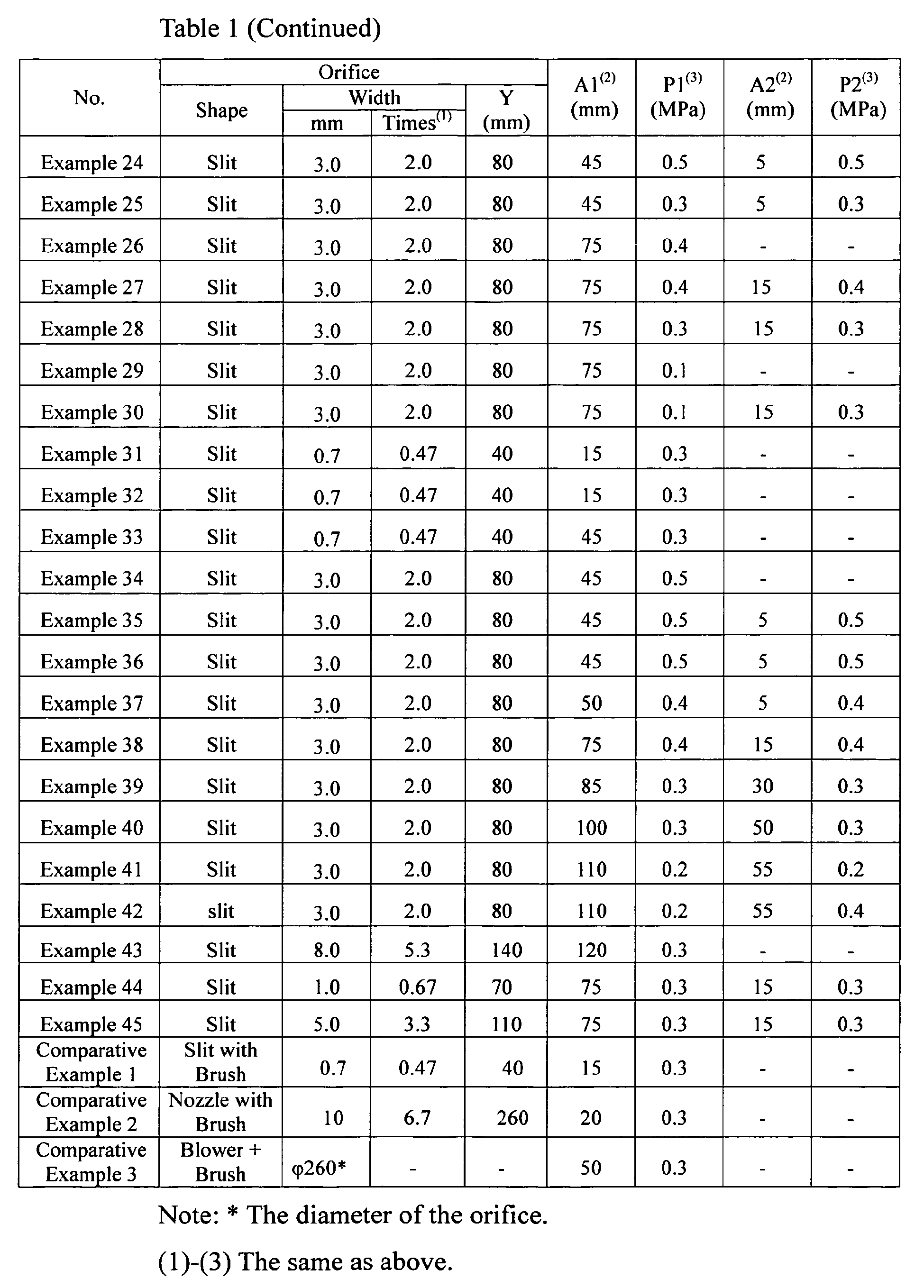


- It is clear from Table 1 that dust and cut pieces were removed from the end surfaces and the cells without damaging the end surfaces of the ceramic honeycomb structure, in Examples 1-45 within the present invention. Among them, in Examples 12, 13, 20, 21, 26-29, dust and cut pieces were effectively removed even from cells near the peripheral wall without damaging the
end surface 32a, because the gap A between theorifice 12 and theend surface 32a was set in two steps; the gap A1 was 50-100 mm in the first step, and the gap A2 was 5-50 mm in the second step. On the other hand, in Comparative Examples 1-3, the end surfaces were damaged by a brush attached to the orifice. - The production method and apparatus of the present invention can effectively remove dust and cut pieces from cells without damaging the end surfaces of the dried or sintered ceramic honeycomb structure, thereby producing a highly reliable ceramic honeycomb filter with dramatically improved efficiency.
Claims (20)
- A method for producing a ceramic honeycomb structure comprising the steps of machining end surfaces of an unsintered or sintered ceramic honeycomb structure, and ejecting a gas from a slit-like orifice moving relative to an opposing end surface without contact, thereby removing dust and/or cut pieces from an end surface portion.
- The method for producing a ceramic honeycomb structure according to claim 1, wherein said slit-like orifice has a slit width of 0.5-5 times the cell pitch of said ceramic honeycomb structure.
- The method for producing a ceramic honeycomb structure according to claim 1 or 2, wherein said gap A is 5-100 mm.
- The method for producing a ceramic honeycomb structure according to any one of claims 1-3, wherein compressed air at pressure P of 0.2-0.5 MPa is ejected from said orifice for cleaning.
- The method for producing a ceramic honeycomb structure according to any one of claims 1-4, wherein said gap A is 1-35% of the length L of said ceramic honeycomb structure.
- The method for producing a ceramic honeycomb structure according to any one of claims 1-5, wherein a gap A between said orifice and said end surface is changed to conduct said cleaning step 2 or more times.
- The method for producing a ceramic honeycomb structure according to claim 6, wherein said gap A is gradually reduced to repeat said cleaning step.
- The method for producing a ceramic honeycomb structure according to claim 6 or 7, wherein said cleaning step is conducted 2 times.
- The method for producing a ceramic honeycomb structure according to claim 8, wherein said gap A is 50-100 mm in the first cleaning step and 5-50 mm in the second cleaning step.
- The method for producing a ceramic honeycomb structure according to any one of claims 1-9, wherein to conduct cleaning, a gas is ejected onto one end surface of said ceramic honeycomb structure, and then onto the other end surface thereof.
- The method for producing a ceramic honeycomb structure according to any one of claims 1-10, wherein dust attached to end surface portions has the maximum diameter of 1.2 mm or less.
- The method for producing a ceramic honeycomb structure according to any one of claims 1-11, wherein cleaning is conducted while the gas is sucked by a hood opposing an end surface on the opposite side of said end surface under cleaning.
- The method for producing a ceramic honeycomb structure according to claim 12, wherein the flow rate Q1 (m3/s) of a gas ejected from said slit-like orifice and the flow rate Q2 (m3/s) of a gas sucked by said hood meet the relation of Q1 < Q2.
- The method for producing a ceramic honeycomb structure according to any one of claims 1-13, wherein after conducting said cleaning, dust remaining in the cells of said ceramic honeycomb structure is inspected.
- The method for producing a ceramic honeycomb structure according to any one of claims 1-14, wherein the amount of water in said unsintered ceramic honeycomb structure is 0.1-2%.
- The method for producing a ceramic honeycomb structure according to any one of claims 1-15, wherein masking members are disposed on an outer peripheral surface of said ceramic honeycomb structure.
- The method for producing a ceramic honeycomb structure according to any one of claims 1-16, wherein the gas ejected from said orifice has a dew point of 10°C or lower.
- The method for producing a ceramic honeycomb structure according to any one of claims 1-17, wherein said ceramic honeycomb structure is cleaned in a substantially horizontal state.
- The method for producing a ceramic honeycomb structure according to any one of claims 1-18, wherein said sintered ceramic honeycomb structure has a porosity of 50-80%.
- An apparatus for producing a ceramic honeycomb structure by cleaning end surface portions of the ceramic honeycomb structure with a gas ejected from an opposing slit-like orifice, comprising a fixing means for gripping an outer peripheral surface of said ceramic honeycomb structure with both end surfaces of said ceramic honeycomb structure kept open, a slit-like orifice opposing one end surface of said ceramic honeycomb structure with a predetermined gap A, a means for supplying a gas to said orifice, and a means for moving said orifice relative to an end surface of said ceramic honeycomb structure without contact.
Applications Claiming Priority (2)
| Application Number | Priority Date | Filing Date | Title |
|---|---|---|---|
| JP2006265108 | 2006-09-28 | ||
| PCT/JP2007/068891 WO2008047565A1 (en) | 2006-09-28 | 2007-09-27 | Method and apparatus for manufacturing ceramic honeycomb structure |
Publications (3)
| Publication Number | Publication Date |
|---|---|
| EP2067589A1 true EP2067589A1 (en) | 2009-06-10 |
| EP2067589A4 EP2067589A4 (en) | 2009-10-21 |
| EP2067589B1 EP2067589B1 (en) | 2012-04-11 |
Family
ID=39313812
Family Applications (1)
| Application Number | Title | Priority Date | Filing Date |
|---|---|---|---|
| EP07828637A Active EP2067589B1 (en) | 2006-09-28 | 2007-09-27 | Method and apparatus for manufacturing ceramic honeycomb structure |
Country Status (7)
| Country | Link |
|---|---|
| US (1) | US8178019B2 (en) |
| EP (1) | EP2067589B1 (en) |
| JP (1) | JP5407331B2 (en) |
| CN (1) | CN101484288A (en) |
| AT (1) | ATE552922T1 (en) |
| BR (1) | BRPI0714960A2 (en) |
| WO (1) | WO2008047565A1 (en) |
Families Citing this family (10)
| Publication number | Priority date | Publication date | Assignee | Title |
|---|---|---|---|---|
| US20120001371A1 (en) * | 2004-07-10 | 2012-01-05 | Mann+Hummel Gmbh | Method for Producing a Ceramic Filter Element |
| JP5377558B2 (en) | 2011-03-30 | 2013-12-25 | 日本碍子株式会社 | Method for cutting honeycomb dried body and honeycomb dried body cutting apparatus |
| US8961707B2 (en) | 2011-06-17 | 2015-02-24 | Lockheed Martin Corporation | Core un-blocking roller brush |
| US9987766B2 (en) * | 2011-12-19 | 2018-06-05 | Dow Global Technologies Llc | Method and apparatus for preparing ceramic body segments |
| JP6011613B2 (en) * | 2012-04-02 | 2016-10-19 | 日立金属株式会社 | Method for manufacturing ceramic honeycomb body |
| JP6041599B2 (en) * | 2012-09-26 | 2016-12-14 | 住友化学株式会社 | Manufacturing method of diesel particulate filter |
| US9499442B1 (en) * | 2013-03-15 | 2016-11-22 | Ibiden Co., Ltd. | Method for manufacturing aluminum-titanate-based ceramic honeycomb structure |
| EP3033201A4 (en) * | 2013-08-14 | 2016-09-07 | United Technologies Corp | Honeycomb removal |
| US10375901B2 (en) | 2014-12-09 | 2019-08-13 | Mtd Products Inc | Blower/vacuum |
| CN106669312B (en) * | 2016-12-15 | 2018-12-25 | 西南科技大学 | A method of utilizing dry gas jetting deashing |
Family Cites Families (26)
| Publication number | Priority date | Publication date | Assignee | Title |
|---|---|---|---|---|
| US4731125A (en) * | 1984-04-19 | 1988-03-15 | Carr Lawrence S | Media blast paint removal system |
| JPS6194717A (en) * | 1984-10-17 | 1986-05-13 | Takara Co Ltd | Molding of figurine and the like and apparatus therefor |
| DE3841513A1 (en) | 1988-12-09 | 1990-06-13 | Metallgesellschaft Ag | METHOD OF DUST DUSTING A CATALYST |
| JPH0755303B2 (en) * | 1992-11-27 | 1995-06-14 | ヒューグルエレクトロニクス株式会社 | Suction nozzle, ultrasonic dust removal nozzle, and ultrasonic dust removal device |
| JP3361901B2 (en) | 1994-10-25 | 2003-01-07 | バブコック日立株式会社 | Honeycomb cut surface cleaning device |
| US5950276A (en) * | 1998-03-03 | 1999-09-14 | Ryobi North America, Inc. | Blower and adjustable blower nozzle attachment |
| US6158082A (en) * | 1998-03-10 | 2000-12-12 | The Toro Company | Portable blower with blower tube noise reduction |
| US6125503A (en) * | 1998-05-12 | 2000-10-03 | Az-Tech Research And Development Corporation | Retracting rotational backpack blower air discharge tube unit |
| JP2000043024A (en) | 1998-07-29 | 2000-02-15 | Ibiden Co Ltd | Method and apparatus for cutting ceramic molded body |
| ES2341274T3 (en) * | 1999-09-29 | 2010-06-17 | Ibiden Co., Ltd. | PANAL FILTER AND CERAMIC FILTER ASSEMBLY. |
| JP4298116B2 (en) * | 2000-02-23 | 2009-07-15 | 日本碍子株式会社 | Manufacturing method and manufacturing apparatus for honeycomb structure with slit |
| DE10201299A1 (en) * | 2001-01-16 | 2002-08-29 | Denso Corp | Process for manufacturing a honeycomb body and drying system |
| JP3672828B2 (en) * | 2001-02-06 | 2005-07-20 | 株式会社丸山製作所 | Air discharge type cleaning machine air duct |
| EP2206693A1 (en) * | 2001-04-23 | 2010-07-14 | Dow Global Technologies Inc. | Wall-flow monolith filter |
| JP4091763B2 (en) | 2001-12-13 | 2008-05-28 | 日本碍子株式会社 | Honeycomb structure and manufacturing method |
| JP4246475B2 (en) * | 2002-04-26 | 2009-04-02 | 日本碍子株式会社 | Manufacturing method of honeycomb structure |
| JP2004273733A (en) * | 2003-03-07 | 2004-09-30 | Seiko Electric Co Ltd | Air nozzle for removing process liquid for printed circuit board and device for removing the same |
| US20040226584A1 (en) * | 2003-05-14 | 2004-11-18 | Michael Guest | Multifunctional surface cleaning machine and method of using the same |
| KR20060017739A (en) * | 2003-05-29 | 2006-02-27 | 니뽄 가이시 가부시키가이샤 | Method for producing honeycomb structure and silicon carbide particles for producing honeycomb structure |
| US7575792B2 (en) * | 2003-07-11 | 2009-08-18 | Ohcera Co., Ltd. | Honeycomb filter for clarifying exhaust gas and method for manufacture thereof |
| CN100339338C (en) * | 2003-07-17 | 2007-09-26 | 旭硝子株式会社 | Method for producing a silicon nitride filter |
| JP4618532B2 (en) | 2004-03-23 | 2011-01-26 | 日立金属株式会社 | Honeycomb body inspection device |
| US7845048B1 (en) * | 2005-06-21 | 2010-12-07 | Gerald Bailey | Portable air-blower for removing debris and the like from a putting green surface |
| ATE551167T1 (en) | 2006-02-28 | 2012-04-15 | Ibiden Co Ltd | METHOD FOR PRODUCING A HONEYCOMB STRUCTURAL BODY |
| JP2007237558A (en) | 2006-03-08 | 2007-09-20 | Asahi Glass Co Ltd | Cutting method of ceramic honeycomb formed body and circular cutting blade |
| ATE425852T1 (en) * | 2006-07-07 | 2009-04-15 | Ibiden Co Ltd | APPARATUS AND METHOD FOR PROCESSING THE END SURFACE OF A HONEYCOMB BODY AND METHOD FOR PRODUCING A HONEYCOMB BODY |
-
2007
- 2007-09-27 US US12/373,170 patent/US8178019B2/en active Active
- 2007-09-27 EP EP07828637A patent/EP2067589B1/en active Active
- 2007-09-27 CN CNA200780025643XA patent/CN101484288A/en active Pending
- 2007-09-27 WO PCT/JP2007/068891 patent/WO2008047565A1/en not_active Ceased
- 2007-09-27 BR BRPI0714960-3A patent/BRPI0714960A2/en not_active Application Discontinuation
- 2007-09-27 AT AT07828637T patent/ATE552922T1/en active
- 2007-09-27 JP JP2008539722A patent/JP5407331B2/en active Active
Also Published As
| Publication number | Publication date |
|---|---|
| US8178019B2 (en) | 2012-05-15 |
| EP2067589A4 (en) | 2009-10-21 |
| JP5407331B2 (en) | 2014-02-05 |
| BRPI0714960A2 (en) | 2013-07-30 |
| EP2067589B1 (en) | 2012-04-11 |
| CN101484288A (en) | 2009-07-15 |
| WO2008047565A1 (en) | 2008-04-24 |
| JPWO2008047565A1 (en) | 2010-02-25 |
| US20090249579A1 (en) | 2009-10-08 |
| ATE552922T1 (en) | 2012-04-15 |
Similar Documents
| Publication | Publication Date | Title |
|---|---|---|
| EP2067589B1 (en) | Method and apparatus for manufacturing ceramic honeycomb structure | |
| EP1875997A1 (en) | End face processing apparatus, end face processing method for honeycomb molded body, and manufacturing method for honeycomb structure | |
| EP2371452B1 (en) | Honeycomb filter production apparatus | |
| EP1825979A1 (en) | Manufacturing method of honeycomb structured body | |
| JP5321064B2 (en) | Base member cleaning method and base member cleaning device | |
| WO2012137655A1 (en) | Ceramic honeycomb filter and method for manufacturing same | |
| EP2905113A1 (en) | Cutting method for honeycomb dried body and production method for honeycomb structure | |
| JP2016132040A (en) | End surface grinding method and end surface grinding device | |
| JP5956892B2 (en) | Band saw cleaning method, green honeycomb molded body cutting method and cutting apparatus | |
| EP2907638A1 (en) | Cutting method for honeycomb dried body, production method for honeycomb structure, honeycomb dried body, and honeycomb structure | |
| JP3361901B2 (en) | Honeycomb cut surface cleaning device | |
| EP2905112A1 (en) | Drying method for honeycomb molded body and production method for honeycomb structure | |
| JP4632125B2 (en) | Method for manufacturing ceramic honeycomb structure | |
| JP5667346B2 (en) | Manufacturing method of honeycomb structure | |
| JP6196234B2 (en) | Improved method and apparatus for making ceramic body segments | |
| JP4461422B2 (en) | Manufacturing method of ceramic honeycomb filter | |
| KR102817320B1 (en) | MCT device including clamping jig | |
| JP2000043024A (en) | Method and apparatus for cutting ceramic molded body | |
| CN113513388A (en) | Method for manufacturing columnar honeycomb structure filter | |
| CN115142933B (en) | Columnar honeycomb filter | |
| JP2015501744A5 (en) | ||
| JP2014065234A (en) | Method for producing diesel particulate filter |
Legal Events
| Date | Code | Title | Description |
|---|---|---|---|
| PUAI | Public reference made under article 153(3) epc to a published international application that has entered the european phase |
Free format text: ORIGINAL CODE: 0009012 |
|
| 17P | Request for examination filed |
Effective date: 20090326 |
|
| AK | Designated contracting states |
Kind code of ref document: A1 Designated state(s): AT BE BG CH CY CZ DE DK EE ES FI FR GB GR HU IE IS IT LI LT LU LV MC MT NL PL PT RO SE SI SK TR |
|
| AX | Request for extension of the european patent |
Extension state: AL BA HR MK RS |
|
| RA4 | Supplementary search report drawn up and despatched (corrected) |
Effective date: 20090908 |
|
| RA4 | Supplementary search report drawn up and despatched (corrected) |
Effective date: 20090918 |
|
| 17Q | First examination report despatched |
Effective date: 20100219 |
|
| REG | Reference to a national code |
Ref country code: DE Ref legal event code: R079 Ref document number: 602007021994 Country of ref document: DE Free format text: PREVIOUS MAIN CLASS: B28B0011180000 Ipc: B08B0005020000 |
|
| RIC1 | Information provided on ipc code assigned before grant |
Ipc: F01N 3/00 20060101ALI20110816BHEP Ipc: B28B 11/22 20060101ALI20110816BHEP Ipc: B08B 5/02 20060101AFI20110816BHEP Ipc: B28B 11/18 20060101ALI20110816BHEP Ipc: C04B 41/91 20060101ALI20110816BHEP Ipc: C04B 41/53 20060101ALI20110816BHEP |
|
| RTI1 | Title (correction) |
Free format text: METHOD AND APPARATUS FOR MANUFACTURING CERAMIC HONEYCOMB STRUCTURE |
|
| GRAP | Despatch of communication of intention to grant a patent |
Free format text: ORIGINAL CODE: EPIDOSNIGR1 |
|
| DAX | Request for extension of the european patent (deleted) | ||
| GRAS | Grant fee paid |
Free format text: ORIGINAL CODE: EPIDOSNIGR3 |
|
| GRAA | (expected) grant |
Free format text: ORIGINAL CODE: 0009210 |
|
| AK | Designated contracting states |
Kind code of ref document: B1 Designated state(s): AT BE BG CH CY CZ DE DK EE ES FI FR GB GR HU IE IS IT LI LT LU LV MC MT NL PL PT RO SE SI SK TR |
|
| REG | Reference to a national code |
Ref country code: GB Ref legal event code: FG4D |
|
| REG | Reference to a national code |
Ref country code: CH Ref legal event code: EP |
|
| REG | Reference to a national code |
Ref country code: AT Ref legal event code: REF Ref document number: 552922 Country of ref document: AT Kind code of ref document: T Effective date: 20120415 |
|
| REG | Reference to a national code |
Ref country code: IE Ref legal event code: FG4D |
|
| REG | Reference to a national code |
Ref country code: DE Ref legal event code: R096 Ref document number: 602007021994 Country of ref document: DE Effective date: 20120606 |
|
| REG | Reference to a national code |
Ref country code: NL Ref legal event code: VDEP Effective date: 20120411 |
|
| REG | Reference to a national code |
Ref country code: AT Ref legal event code: MK05 Ref document number: 552922 Country of ref document: AT Kind code of ref document: T Effective date: 20120411 |
|
| LTIE | Lt: invalidation of european patent or patent extension |
Effective date: 20120411 |
|
| PG25 | Lapsed in a contracting state [announced via postgrant information from national office to epo] |
Ref country code: SE Free format text: LAPSE BECAUSE OF FAILURE TO SUBMIT A TRANSLATION OF THE DESCRIPTION OR TO PAY THE FEE WITHIN THE PRESCRIBED TIME-LIMIT Effective date: 20120411 Ref country code: IS Free format text: LAPSE BECAUSE OF FAILURE TO SUBMIT A TRANSLATION OF THE DESCRIPTION OR TO PAY THE FEE WITHIN THE PRESCRIBED TIME-LIMIT Effective date: 20120811 Ref country code: LT Free format text: LAPSE BECAUSE OF FAILURE TO SUBMIT A TRANSLATION OF THE DESCRIPTION OR TO PAY THE FEE WITHIN THE PRESCRIBED TIME-LIMIT Effective date: 20120411 Ref country code: PL Free format text: LAPSE BECAUSE OF FAILURE TO SUBMIT A TRANSLATION OF THE DESCRIPTION OR TO PAY THE FEE WITHIN THE PRESCRIBED TIME-LIMIT Effective date: 20120411 Ref country code: CY Free format text: LAPSE BECAUSE OF FAILURE TO SUBMIT A TRANSLATION OF THE DESCRIPTION OR TO PAY THE FEE WITHIN THE PRESCRIBED TIME-LIMIT Effective date: 20120411 Ref country code: FI Free format text: LAPSE BECAUSE OF FAILURE TO SUBMIT A TRANSLATION OF THE DESCRIPTION OR TO PAY THE FEE WITHIN THE PRESCRIBED TIME-LIMIT Effective date: 20120411 |
|
| PG25 | Lapsed in a contracting state [announced via postgrant information from national office to epo] |
Ref country code: PT Free format text: LAPSE BECAUSE OF FAILURE TO SUBMIT A TRANSLATION OF THE DESCRIPTION OR TO PAY THE FEE WITHIN THE PRESCRIBED TIME-LIMIT Effective date: 20120813 Ref country code: SI Free format text: LAPSE BECAUSE OF FAILURE TO SUBMIT A TRANSLATION OF THE DESCRIPTION OR TO PAY THE FEE WITHIN THE PRESCRIBED TIME-LIMIT Effective date: 20120411 Ref country code: GR Free format text: LAPSE BECAUSE OF FAILURE TO SUBMIT A TRANSLATION OF THE DESCRIPTION OR TO PAY THE FEE WITHIN THE PRESCRIBED TIME-LIMIT Effective date: 20120712 Ref country code: LV Free format text: LAPSE BECAUSE OF FAILURE TO SUBMIT A TRANSLATION OF THE DESCRIPTION OR TO PAY THE FEE WITHIN THE PRESCRIBED TIME-LIMIT Effective date: 20120411 |
|
| PG25 | Lapsed in a contracting state [announced via postgrant information from national office to epo] |
Ref country code: BE Free format text: LAPSE BECAUSE OF FAILURE TO SUBMIT A TRANSLATION OF THE DESCRIPTION OR TO PAY THE FEE WITHIN THE PRESCRIBED TIME-LIMIT Effective date: 20120411 |
|
| PG25 | Lapsed in a contracting state [announced via postgrant information from national office to epo] |
Ref country code: AT Free format text: LAPSE BECAUSE OF FAILURE TO SUBMIT A TRANSLATION OF THE DESCRIPTION OR TO PAY THE FEE WITHIN THE PRESCRIBED TIME-LIMIT Effective date: 20120411 Ref country code: NL Free format text: LAPSE BECAUSE OF FAILURE TO SUBMIT A TRANSLATION OF THE DESCRIPTION OR TO PAY THE FEE WITHIN THE PRESCRIBED TIME-LIMIT Effective date: 20120411 Ref country code: DK Free format text: LAPSE BECAUSE OF FAILURE TO SUBMIT A TRANSLATION OF THE DESCRIPTION OR TO PAY THE FEE WITHIN THE PRESCRIBED TIME-LIMIT Effective date: 20120411 Ref country code: SK Free format text: LAPSE BECAUSE OF FAILURE TO SUBMIT A TRANSLATION OF THE DESCRIPTION OR TO PAY THE FEE WITHIN THE PRESCRIBED TIME-LIMIT Effective date: 20120411 Ref country code: RO Free format text: LAPSE BECAUSE OF FAILURE TO SUBMIT A TRANSLATION OF THE DESCRIPTION OR TO PAY THE FEE WITHIN THE PRESCRIBED TIME-LIMIT Effective date: 20120411 Ref country code: EE Free format text: LAPSE BECAUSE OF FAILURE TO SUBMIT A TRANSLATION OF THE DESCRIPTION OR TO PAY THE FEE WITHIN THE PRESCRIBED TIME-LIMIT Effective date: 20120411 Ref country code: CZ Free format text: LAPSE BECAUSE OF FAILURE TO SUBMIT A TRANSLATION OF THE DESCRIPTION OR TO PAY THE FEE WITHIN THE PRESCRIBED TIME-LIMIT Effective date: 20120411 |
|
| PLBE | No opposition filed within time limit |
Free format text: ORIGINAL CODE: 0009261 |
|
| STAA | Information on the status of an ep patent application or granted ep patent |
Free format text: STATUS: NO OPPOSITION FILED WITHIN TIME LIMIT |
|
| PG25 | Lapsed in a contracting state [announced via postgrant information from national office to epo] |
Ref country code: IT Free format text: LAPSE BECAUSE OF FAILURE TO SUBMIT A TRANSLATION OF THE DESCRIPTION OR TO PAY THE FEE WITHIN THE PRESCRIBED TIME-LIMIT Effective date: 20120411 |
|
| 26N | No opposition filed |
Effective date: 20130114 |
|
| PG25 | Lapsed in a contracting state [announced via postgrant information from national office to epo] |
Ref country code: MC Free format text: LAPSE BECAUSE OF NON-PAYMENT OF DUE FEES Effective date: 20120930 Ref country code: ES Free format text: LAPSE BECAUSE OF FAILURE TO SUBMIT A TRANSLATION OF THE DESCRIPTION OR TO PAY THE FEE WITHIN THE PRESCRIBED TIME-LIMIT Effective date: 20120722 |
|
| REG | Reference to a national code |
Ref country code: CH Ref legal event code: PL |
|
| REG | Reference to a national code |
Ref country code: DE Ref legal event code: R097 Ref document number: 602007021994 Country of ref document: DE Effective date: 20130114 |
|
| GBPC | Gb: european patent ceased through non-payment of renewal fee |
Effective date: 20120927 |
|
| REG | Reference to a national code |
Ref country code: IE Ref legal event code: MM4A |
|
| PG25 | Lapsed in a contracting state [announced via postgrant information from national office to epo] |
Ref country code: LI Free format text: LAPSE BECAUSE OF NON-PAYMENT OF DUE FEES Effective date: 20120930 Ref country code: BG Free format text: LAPSE BECAUSE OF FAILURE TO SUBMIT A TRANSLATION OF THE DESCRIPTION OR TO PAY THE FEE WITHIN THE PRESCRIBED TIME-LIMIT Effective date: 20120711 Ref country code: GB Free format text: LAPSE BECAUSE OF NON-PAYMENT OF DUE FEES Effective date: 20120927 Ref country code: CH Free format text: LAPSE BECAUSE OF NON-PAYMENT OF DUE FEES Effective date: 20120930 Ref country code: IE Free format text: LAPSE BECAUSE OF NON-PAYMENT OF DUE FEES Effective date: 20120927 |
|
| PG25 | Lapsed in a contracting state [announced via postgrant information from national office to epo] |
Ref country code: MT Free format text: LAPSE BECAUSE OF FAILURE TO SUBMIT A TRANSLATION OF THE DESCRIPTION OR TO PAY THE FEE WITHIN THE PRESCRIBED TIME-LIMIT Effective date: 20120411 |
|
| PG25 | Lapsed in a contracting state [announced via postgrant information from national office to epo] |
Ref country code: TR Free format text: LAPSE BECAUSE OF FAILURE TO SUBMIT A TRANSLATION OF THE DESCRIPTION OR TO PAY THE FEE WITHIN THE PRESCRIBED TIME-LIMIT Effective date: 20120411 |
|
| PG25 | Lapsed in a contracting state [announced via postgrant information from national office to epo] |
Ref country code: LU Free format text: LAPSE BECAUSE OF NON-PAYMENT OF DUE FEES Effective date: 20120927 |
|
| PG25 | Lapsed in a contracting state [announced via postgrant information from national office to epo] |
Ref country code: HU Free format text: LAPSE BECAUSE OF FAILURE TO SUBMIT A TRANSLATION OF THE DESCRIPTION OR TO PAY THE FEE WITHIN THE PRESCRIBED TIME-LIMIT Effective date: 20070927 |
|
| REG | Reference to a national code |
Ref country code: FR Ref legal event code: PLFP Year of fee payment: 10 |
|
| REG | Reference to a national code |
Ref country code: FR Ref legal event code: PLFP Year of fee payment: 11 |
|
| REG | Reference to a national code |
Ref country code: FR Ref legal event code: PLFP Year of fee payment: 12 |
|
| PGFP | Annual fee paid to national office [announced via postgrant information from national office to epo] |
Ref country code: DE Payment date: 20250805 Year of fee payment: 19 |
|
| PGFP | Annual fee paid to national office [announced via postgrant information from national office to epo] |
Ref country code: FR Payment date: 20250808 Year of fee payment: 19 |
|
| REG | Reference to a national code |
Ref country code: DE Ref legal event code: R081 Ref document number: 602007021994 Country of ref document: DE Owner name: MIRAI CASTING AMERICA, INC., FARMINGTON HILLS, US Free format text: FORMER OWNER: HITACHI METALS, LTD., TOKIO/TOKYO, JP Ref country code: DE Ref legal event code: R081 Ref document number: 602007021994 Country of ref document: DE Owner name: MIRAI CASTING AMERICA, INC., FARMINGTON HILLS, US Free format text: FORMER OWNER: PROTERIAL, LTD., TOKYO, JP |
|
| REG | Reference to a national code |
Ref country code: DE Ref legal event code: R081 Ref document number: 602007021994 Country of ref document: DE Owner name: MIRAI CASTING AMERICA, INC., FARMINGTON HILLS, US Free format text: FORMER OWNER: MIRAI CASTING HOLDINGS, LTD., TOKYO, JP |